

Page 1

TRP-C28
4-channel isolated digital input and 4-channel power relay output
RS485 module, Support ASCII and Modbus Protocol.
User’s Manual
Printed May. 2011 Rev 1.3
Trycom Technology Co.,Ltd
1F, No.2-11,Sihu street ,Yingge Township, Taipei, Taiwan ROC
Tel: 886-2-86781191 , Fax: 886-2-86781172
www.trycom.com.tw
Copyright
Copyright Notice: The information in this manual is subject to change without prior notice in order to improve reliability, design and function and
dosed not represent a commitment on the part of the manufacturer. No part of this manual may be reproduced, copied, or transmitted in any
form without the prior written permission of manufacturer. Acknowledgment Products mentioned in this manual are mentioned for identification
purpose only. Products manes appearing in this manual may or may not be registered trademarks or copyright of their respective companies.
1
Page 2

1.Introduction
TRP-C28 provides with 4 optical isolated digital input channels and 4 power relays output. All
channel features screw terminals for convenient connection of field signals as well as LED’s to
indicate channel status. Input channels are equipped with 3750Vms DC isolation, and surge
protection on RS485 data lines that protect the module and devices against high power voltage
input and ground potential differences. For easy user access, TRP-C28 can enter configuration
mode and self-test mode with outer dip-switch. TRP-C28 support both ASCII and Modbus
protocol, with a full set of command, dual watch-dog, and auto reset function the module can be
bi-directionally remote controlled by PC in ASCII or Modbus RTU protocol.
1-1.Features
Wide input range DC power supply.
Support ASCII and Modbus RTU protocol.
Supports baud rates from 1.2Kbps to 115.2 Kbps.
All 4 channels digital input ca be used as counter.
Digital input signal with 3750Vrms isolation protection.
Dual watchdog: Module’s firmware, host computer traffic.
LED for each channels working status.
DIN rail and panel mount support.
Configured and self-test by outer dip-switch.
Support screw terminal and external DC power adaptor.
1-2.Specifications
Input channel: 4 digital input channels.
Input optical isolation: 3750 Vrms.
Input logical level 0: ±1V (max).
Input logical level 1: ±4.0V ~ ±30V.
Communication interface: RS485.
Communication speed: Baud rate from 1.2kbps to 115.2Kbps.
Input impedance: 3Kohm.
Distance: 500M (max).
Digital Input can be used as counter channel: 4.
Counter frequency: 100Hz.
Output channel: 4 channel power reply outputs.
Relay type: 2 Form A (RL1,RL2) , 2 Form C (RL3,RL4).
Contact ratting: 6A/24V DC , 6A/120V AC , 5A/250V AC.
Relay surge strength: 4000V.
Relay operating time: 6ms.
Relay operating life: 1 X 10(7).
Dual watchdog: Hardware reset circuit, module and host operating status.
2
Page 3
Signal LED: Power on, all channels.
Power supply: Screw terminal, or external DC adapter.
Connection type: Screw terminal, accepts AWG #12~32 wires.
Power consumption: 2.7W.
Operating environment: 0 to 65C.
Storage temperature: -20 to 65C.
Humidity: 10-90% Non-condensing.
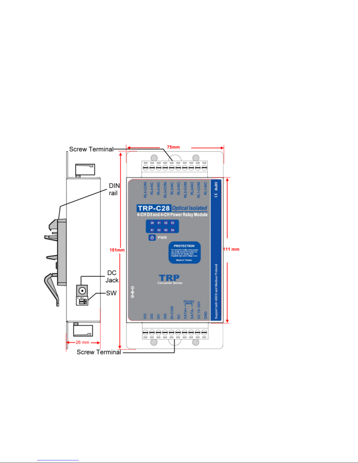
Dimension: 151mm X 75mm X 26mm.
Weight: 400g.
1-3. Panel Layout
1-4.Block Diagram
3
Page 4
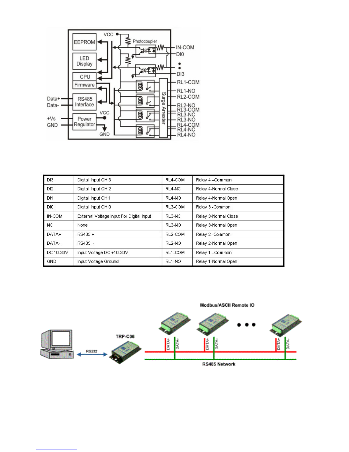
1-5. Pin Definitions
2. Communication Wiring
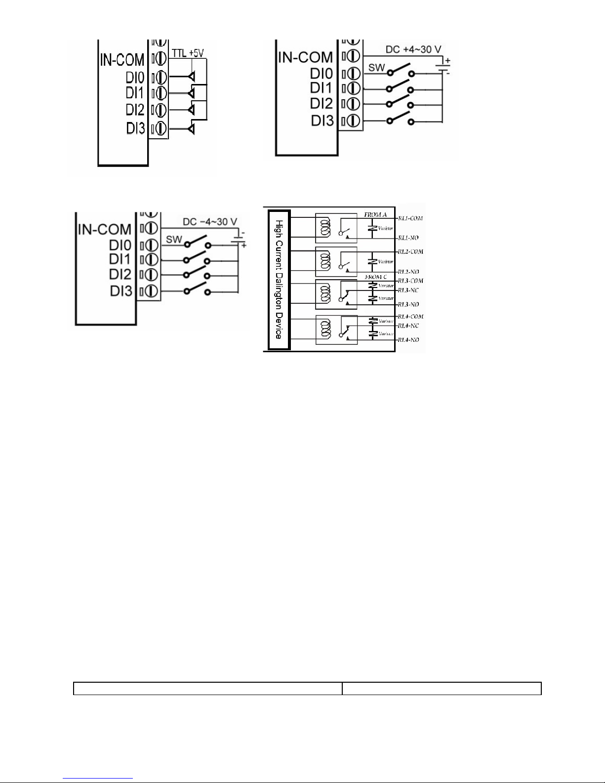
3. Wire Connection
4
Page 5
4. System Configuration Switch
The TRP-C28 support the Modbus RTU and ASCII communication protocol, It has a two pins
external dip-switch that allow user to select protocol between Modbus/RTU and ASCII. The dipswitch also provides “back to default” function when user forget the configuring information
stored in EEPROM such as ID (RS-485 Module address), baud rate and data format.
Default setting:
ID Address: 01,
Baud Rate: 9600,
DIO Mode Type: 40,
Checksum: Disable,
RS485 Communication data format: N, 8, 1.
Modbus Protocol (Factory)
5
Page 6
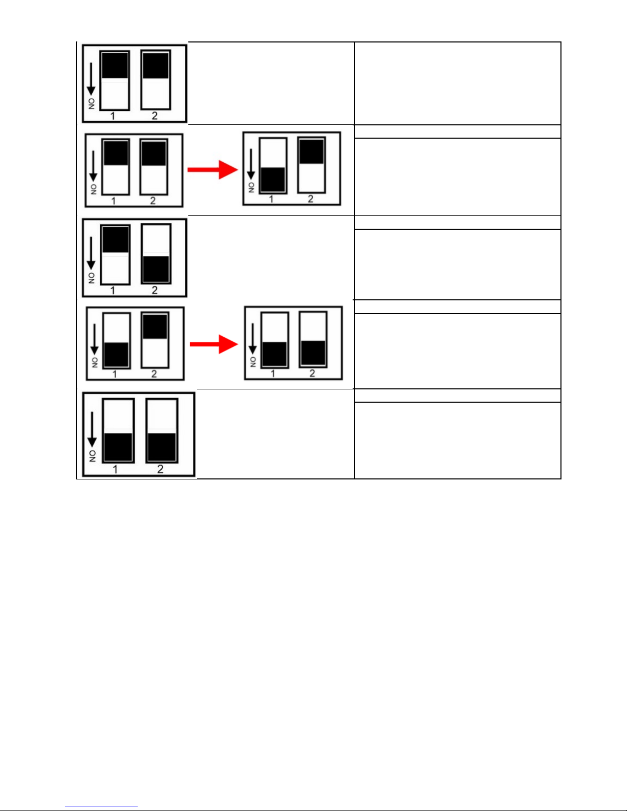
Modbus Communication Protocol.
Back to INIT for Modbus
1. Adjust the switch to “off off” position
2. Adjust the switch to “on off” position
3. Reboot.
ASCII Protocol
ACSII communication protocol.
Back to INIT for ASCII
1. Adjust the switch to “on off” position
2. Adjust the switch to “on on” position
User may adjust the switch in power on
status, no system reboot require.
Enter self- test mode
Adjust the switch to on on then reboot.
*INIT: ID=00, Baud-Rate: 9600, Data format: 00, Checksum=disable.
5. Function description
Power on mode: When power fail, system reset or host watchdog timeout will cause the
module reboot then into power on mode, the module’s digital output value will return to the
before setting.
And module can accept the host’s command to change the digital output value.
Dual Watchdog: Module self watchdog: The module’s watchdog is a hardware reset circuit
while working in harsh or noisy environment, the module may be down by the external, The
circuit may let the module to work continues and never halt.
Host watchdog: The host watchdog is software function to monitor the module's output states to
prevent the module from communication problem or system halt due to unexpected situation,
It’s purpose is to prevent the RS485 network from communication problem or host halt. When
the timeout interval expired, the module will turn all output to predefined safe value. This can
6
Page 7

prevent the controlled target from unexpected situation.
Safe mode: If the user install the watch-dog enable on the RS485 line, The host will send the
reset module’s watchdog command one by one, when the host is not send the command (May
be is RS485 off line or host halt), the module will watchdog timeout then into the safe mode, if
the module into the safe mode, the digital out will not be changed until the watchdog disable.
6. TRPCOM Command Protocol Description
Command Format :”Leading Code”+”ID Address”+”Command”+”CHK”+(cr).
Response Format :”Leading Code”+”ID Address”+”Data”+”CHK”+(cr).
7. How to Calculate the Checksum
1. Calculate all characters of the command string to get the ASCII sum, except the character
return.
2. Mask the sum of string with 0FFH.
Example:
Send the command is “$06M”.
Sum of string is “$”+”0”+”6”+”M”=“24H”+”30H”+” 4D“=“A1H”……The checksum and [CHK]=“A1”.
Response string with checksum is:” A1 “.
7
Page 8

8. Command List
Command List Function Description Page Index
%IDNNPPBBDD(CHK)(cr) Set the module’s configuration See 8-1 ~ 8-3
#IDPPFD(CHK)(cr) Digital output data See 8-4
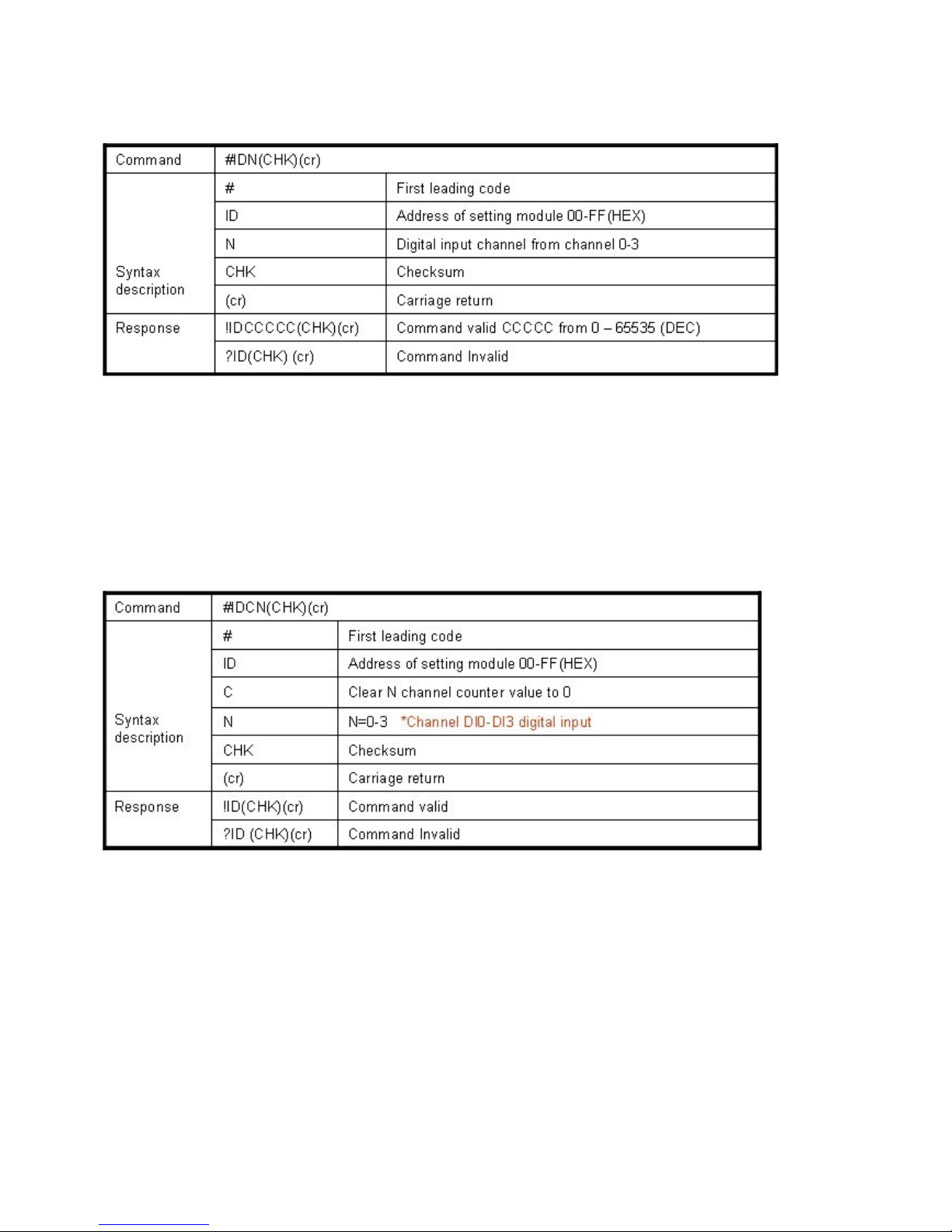
#IDN(CHK)(cr) Read digital input N channel counter value See 8-5
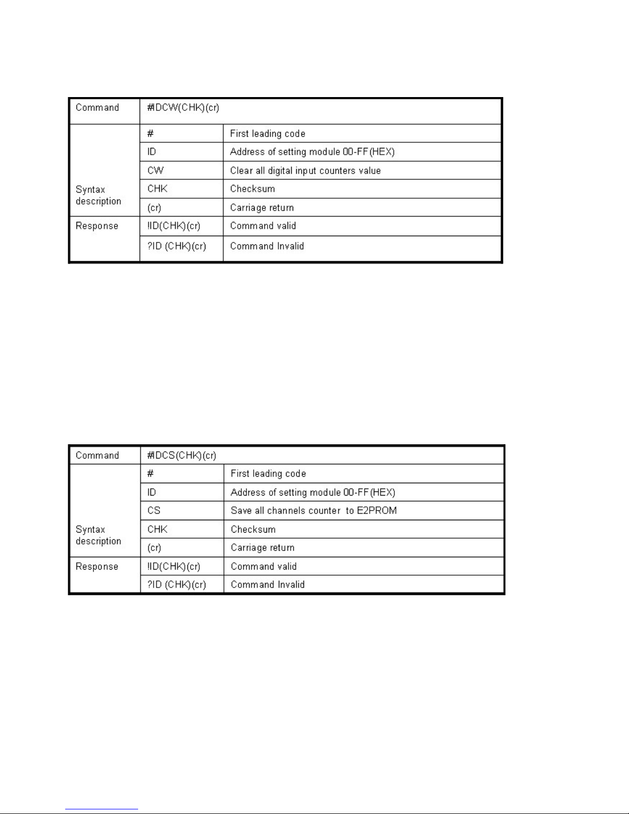
#IDCN(CHK)(cr) Clear digital input N channel counter value See 8-6
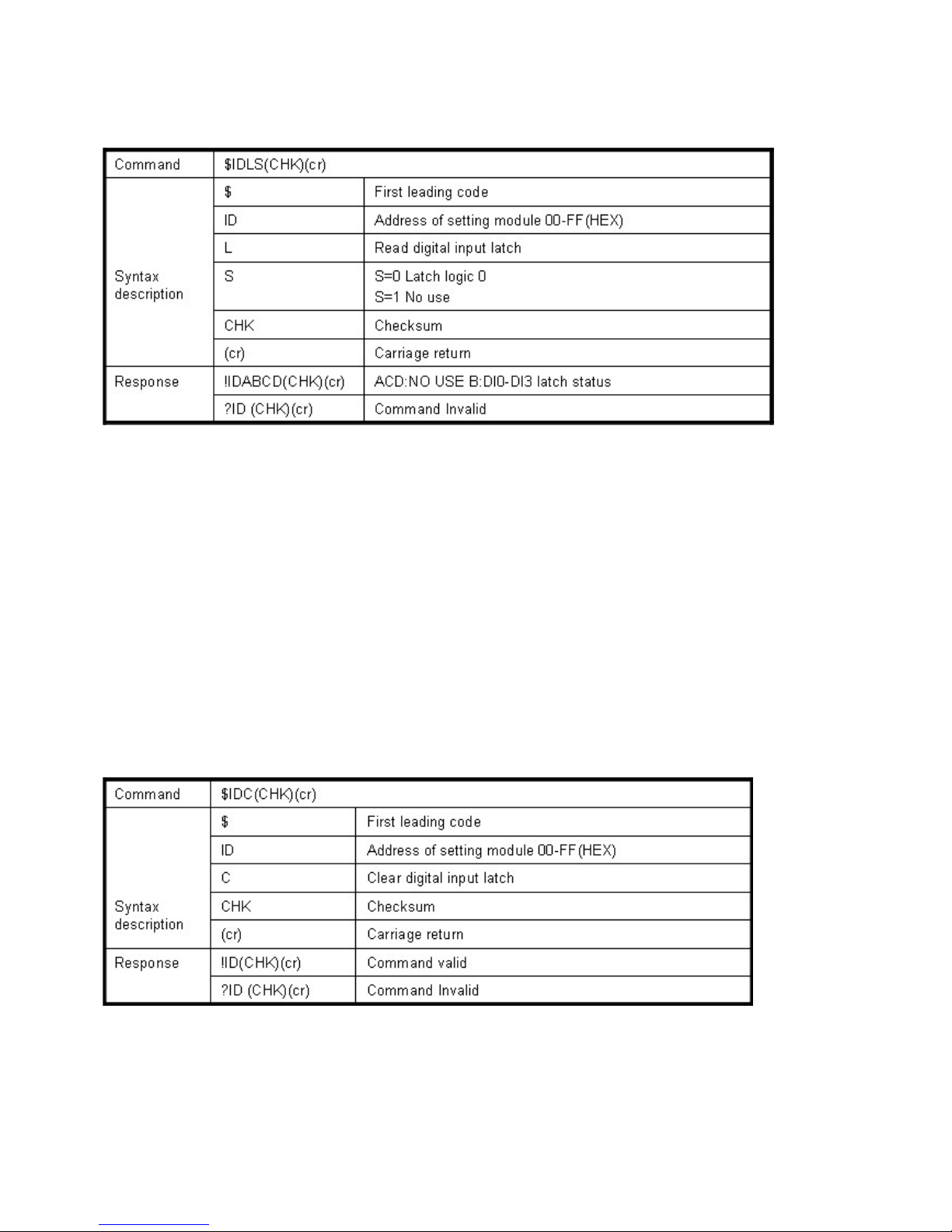
#IDCW(CHK)(cr) Clear all digital input counters value See 8-7
#IDCS(CHK)(cr) Save all digital input counters value to EEPROM See 8-8
$IDLS(CHK)(cr) Read digital input latched See 8-9
$IDC(CHK)(cr) Clear digital input latched See 8-10
$ID6(CHK)(cr) Read digital input/output status See 8-11
$ID2(CHK)(cr) Read the TRP-C28M configuration See 8-12
$IDRS(CHK)(cr) Reset the module status See 8-13
$IDM(CHK)(cr) Read the module’s name See 8-14
$IDF(CHK)(cr) Read the module’s firmware version See 8-15
$ID5(CHK)(cr) Read the module reset status See 8-16
~IDONN(CHK)(cr) Change the module’s name See 8-17
~IDLEDA(CHK)(cr) Set the module’s LED operating mode See 8-18
~IDWENN(CHK)(cr) Enable watchdog and set the timeout value See 8-19
~IDWD(CHK)(cr) Disable watchdog See 8-20
~IDWR(CHK)(cr) Read watchdog timeout value See 8-21
~**(CHK)(cr) System stand by (Host OK!) See 8-22
~ID4V(CHK)(cr) Read power on/safe value See 8-23
~ID5V(CHK)(cr) Save current digital output status to power on or safe mode See 8-24
#**(CHK)(cr) Save current digital input status See 8-25
$ID4(CHK)(cr) Read synchronized data See 8-26
*We offer the utility to guide you to configure the module; the utility is with on-line RS485
modules scanning and searching function. You can find the utility in the CD which bundled in
TRP-C28 standard package.
8
Page 9
8-1. Configure TRP-C28
Command %IDNNPPBBDD(CHK)(cr)
Syntax
Description
% First leading code
ID Address of setting module 00-FF(HEX)
NN New address of setting from 00-FF(HEX)
PP The Digital I/O module type define to 40
BB Set new baud rate (See 8-2)
DD Data format (See 8-3)
CHK Checksum
(cr) Carriage return
Response !ID(CHK)(cr) Command valid
?ID(CHK)(cr) Command Invalid
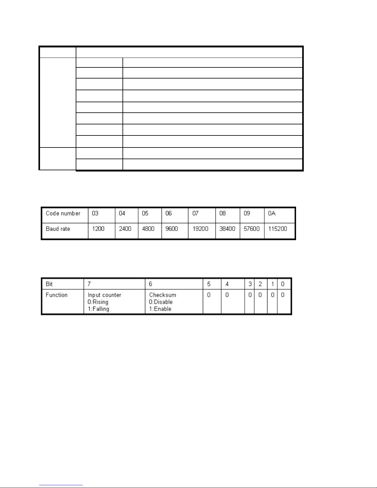
8-2 Baud rate setting (BB)
8-3 Data format setting (DD)
Example:
Send command:”%0001400600”…If you turn on the system setting switch, the ID will be reset
to “00”,
New ID is “01”,D I/O type is “40” ,Bard-Rate:9600 ,Checksum setting disable is “00”,
Response:”!01”.
Example:
Send command:%000340054
New ID=“03”,Bard-Rate=“4800”,Checksum=“Enable”,Response:”!03”.
9
Page 10

8-4. Digital output data
*Multi-Channel mode (Output control for one BYTE)
Example:
Send command :”#010A0F”…..Data=”0F”:DO0-DO3=“1111”, (RL1/RL2/RL3/RL4= ON).
Response:”>”……. Command valid.
Example:
Send command:”#010008”…..Data=”08”:DO0-DO3=“0001”,(RL1/RL2/RL3:OFF/RL4:ON).
Response:”>”……. Command valid.
Example:
Send command:”#01000G”…Data=“0G”…….Data error!.
Response:”!01”…….Parameter error!.
*Single-Channel mode( Output control for one BIT)
Example:
Send command:”#011001”….. Data=”01”:DO0=“1”.
Response:”>”……. Command valid.
Send command:”#011201”….. Data=“01”:DO2=“1”.
Response:”>”……. Command valid.
Send command:#011300……Data=“00”:DO3=“0”.
Response:”>”……..Command valid.
10
Page 11
8-5. Read digital input N channel counter value
Example:
Send command:”#012”…..Read the TRP-C28M channel 2 counter value.
Response:”!0100023”…..The digital input have been trigger 23 times.
*Unless you save value to EEPROM by using the command “#IDCS”. The counter’s value will
reset to 0 if power fail or send command “$IDRS”.
8-6. Clear digital input N channel counter value
Example:
Send command:”#01C2”, Clear DI2 counter value to 0.
Response:”!01”.
*If counter’s value already been reset to 0 you must use command “#IDCS” to save the new
value in EEPROM again, or the module will load old value if power fail or reset.
11
Page 12
8-7.Clear all digital input counters value
Example:
Send command: ”#01CW”, Clear DI0-DI3 counter value to 0.
Response:”!01”.
* After the command “#IDCW” you must save new value in EEPROM again, or the module will
load old value if power fail or reset.
8-8.Save all digital input counters value to EEPROM
Example:
Send command ”#01CS”, Save DI0-DI3 counters value to EEPROM.
Response:”!01”.
Then after power fail or reset
Send command:”#010”……..Read DI0 counter value.
Response:”!0100187”………..Last time save value is “187”.
12
Page 13
8-9.Read digital input latched
Example:
Send command:”$01L0”…….Read digital input logic 0.
Response:”!010200 ”……… DI1 have been latched.
*Digital input latch: User key in a digital signal to the module and want to read the response of
key stoke. However the user will lost the stoke information because the key input is pulse digital
input. If user read by the command “$ID6” in time A and time B, the response is that no key
stoke. Use command $IDLS can solve this problem, user may read the key stoke in time
position A and B.
8-10.Clear digital input latched
Example:
Send command:”$01C”…….Clear digital input latch .
Response:”!01 ”……………. …Latch have been clear.
13
Page 14

8-11. Read digital input/output status
Example:
Send command:$016…….Read digital I/O status .
Response:”!01060C”…….”6”: Relay (RL1,RL4:OFF,RL2,RL3:ON).
“
C”: Input DI0 ,DI1 for logic “
0”.
8-12.Read the TRP-C28M configuration
Data format table
14
Page 15

Example:
Send command:$012…Read configuration .
Response:”!01400640”……. DIO type=40,Baud-Rate=9600 (See 7.2) ,Data format=40 Input
counter :rising ,Checksum= Enable, Model=0….TRP-C28M (See Data format table
),
8-13.Reset the module status
Example:
Send command:”$01RS”…….Reset TRP-C28M.
Response:”!01 ”……… …………..Have been reset.
*Reset will clear all digital output status.
8-14.Read the module’s name
Example:
Send command:$01M…Read the TRP-C28M’s name.
Response:”!01TRPC28”……. The module’s name is “TRPC28”.
15
Page 16

8-15.Read the module’s firmware version
$IDF(CHK)(cr)
Syntax
description
$ First Leading code
ID Address of setting module 00-FF(HEX)
F Command for leading module’s version
CHK Checksum
(cr) Carriage return
Response !IDMODYYMMDD Mod: The module type
YY: Year
MM: Month
DD: Date
?ID(CHK)(cr)
Example:
Send command:”$01F”…Read the TRP-C28M’s version.
Response:”!01C28M070412”……. The TRP-C28M’s version date is “04/12/2007”.
8-16. Read the module reset status
Example:
Send command:$015…Read the TRP-C28M’s reset state .
Response:”!011”……. The TRP-C28M has been reset.
*If the module is system halt or detect abnormal voltage, the module will restart and reset the
flag to “1”.
16
Page 17

8-17.Change the module’s name
Example:
Send command:”~01OABCDE”….. Change the TRP-C28M’s name become to “ABCDE”.
Response:”!01”……. . Command valid.
Then send the command “$01M”…read the TRP-C28M’s name.
Response:”!01ABCDE”……. .The TRP-C28M’s name is “ABCDE”.
8-18.Set the module’s LED operating mode
~IDLEDA(CHK)(cr)
Syntax
description
~ First Leading code
ID Address of setting module 00-FF(HEX)
A A=0 Turn on all LED when DIO enable off.
A=1 Turn off all LED when DIO enable on.
CHK Checksum
(cr) Carriage return
Response !IDON/OFF Command valid
?ID(CHK)(cr) Command invalid
Example:
Send command:”~01LED0”….. Turn off all LED, when logic “1” ON.
Response:”!01OFF”……..Command valid.
8-19.Enable watchdog and set the timeout value
17
Page 18

Example:
Send Command:”~01WEFF”….. Set the watchdog time for 25.5 Sec.
Response:”!01”……. . Command valid, When module count to 25.5 Sec the watchdog will into
safe mode ,then PWR LED will flash, before timeout if host send “~**”, the watchdog will recounted!.
*When the module is in safe mode, any digital output command are invalid, you will get the
response “!IDWE” , which means the system is in safe mode, you can't change output status.
*Reset and power fail will not affect watchdog mode.
8-20. Disable watchdog
Example:
Send Command:”~01WD”….. Watchdog disable!.
Response:”!01”……. . Command valid, System LED will stop flashing!.
8-21. Read watchdog timeout value
18
Page 19

Example:
Send Command:”~01WR”…. Read watchdog timeout value.
Response:” !01WD0F”……. . Command valid, set the watchdog timeout is “0F”..1.6 Sec.
8-22.System stand by (Host OK!)
*If watchdog is in enable , send the Host Ok!”command before watchdog timeout (B) the
watchdog will re-count, PWR LED will flashing after watchdog timeout.
8-23.Read power on/safe value
19
Page 20

Command ~ID4V(CHK)(cr)
Syntax
description
~ First Leading code
ID Address of setting module 00-FF(HEX)
4 Read power on or safe mode I/O status
V V=P: Power on mode I/O status
V=S: Safe mode I/O status
CHK Checksum
(cr) Carriage return
Response !IDABCD A=0 B:DO0~DO3
B=0 D:DI0~DI3
?ID(CHK)(cr) Command invalid
Example:
Send Command:~014S……….Read safe mode digital output status.
Response:” !01080F”………. . Command valid, safe mode digital IO status is ”080F”.
8-24. Save current digital output status to power on or safe mode
Example:
Send Command:”#010A0F”…Relay output RL1~RL4= ON/ON/ON/ON
Response:” !01”……. . Command valid!
Then Send Command :” ~015P”….Set the relay output for power on ,.After power fail or reset ,
The module will load current DO status.
8-25. Save current digital input /output status
20
Page 21

Example:
Send Command:”#**”………. Save current digital IO status of all modules on line.
8-26.Read synchronized data
Example:
Send Command:”#**”……….Save current digital IO status( All modules on line).
Then send command:”$014”…. Read synchronized data
Response:”!1010E00”….”1”:Have been send the “#**,the DIO status valid is “010E” *After Read
*synchronized data ,A value is”1”, Read again become to ”0”.
9. Modbus/RTU Command Description
The TRP-C28 support Modbus/RTU protocol, The serial communication data format is
21
Page 22

Start bit: 1
Data bit: 8
Parity check: None
Stop bit: 1
Baud-rate: 1200bps~115200bps.
9-1. Modbus Syntax:
Command Format :ID(HEX)+FC(HEX)+SU(HEX)+DA(HEX) or RC(HEX)+CRC16(HEX).
Response Format : ID(HEX)+FC(HEX)+SU(HEX)+DA(HEX) or RC(HEX)+CRC16(HEX).
Error Format: ID(HEX)+ FC(HEX)+ CRC16(HEX).
ID: RS485 Device Address (HEX)…..1~247 1Byte.
FC: Function Code (HEX)…1 Byte.
SU: Sub Function (HEX)…..1 Byte
DA: Data Format….No Limit
RC: Reserved code…No Limit
CRC: Cyclic Redundancy Check…2 Byte
*Error Response: If CRC IS mismatches error the response is empty!
10. Modbus RTU Command List
22
Page 23

Command List Function Description Index
ID 46 00 00 (CRC) Read the module’s name 10-1
ID 46 04 IP 00 00 00 (CRC) Set up the module’s address 10-2
ID 46 05 00 (CRC) Read the module’s configuration 10-3
ID 46 06 00 BD 00 00 00 00 00 00 (CRC) Set up the module’s configuration 10-4
ID 46 07 00 (CRC) Read the module’s Firmware 10-5
ID 46 08 00(CRC) Read module reset status 10-6
ID 46 09 00 (CRC) Set up the module reset 10-7
ID 46 0B WS 00 (CRC) Set up watchdog timeout value or disable 10-8
ID 46 0C 00 (CRC) Read watchdog status 10-9
ID 46 0D 0S 00 (CRC) Set up LED panel status 10-10
ID 46 27 DD 00 (CRC) Set up power on mode 10-11
ID 46 28 00 (CRC) Read power on mode value 10-12
ID 46 29 DD 00 (CRC) Set up safe mode value 10-13
ID 46 2A 00 (CRC) Read safe mode value 10-14
ID 05 00 NN DD 00 (CRC) Set up single channel digital output status 10-15
ID 0F 00 00 00 04 01 DD (CRC) Set up the digital output status 10-16
ID 01 00 SS 00 04 (CRC) Read digital input/output status 10-17
ID 02 00 SS 00 04 (CRC) Read digital input/output status 10-18
ID 03 00 SS 00 NN (CRC) Read digital input counter value 10-19
ID 04 00 SS 00 NN (CRC) Read digital input counter value 10-20
ID 0F SS NN 00 CN BC 00 (CRC) Clear/save DI counter value and set up DO output 10-21
10-1.Read the module’s name
Command ID 46 00 00 (CRC)
23
Page 24

Syntax
Description
ID Address of setting module 1~247
46 Function code
00 Read module’s name
00 Reserved code
Response ID 46 00 00 0C 28 00 (CRC) ID 46 00 00 ….Module command Line
0C 28 :Module’s Name is C28
ID C6 00(CRC) ID C6 (CRC) C6:Function Code 00: Reserved code
EX: Send Command:”01 46 00 00”…….Read the TRP-C24’s name
Response:”01 46 00 00 0C 28 00 “……Module’s name is C24
Error Response: “01 C6 00”……Error code
10-2.Set up the module’s address
Command ID 46 04 IP 00 00 00 (CRC)
Syntax
Description
ID Address of setting module 1~247
46 Function Code
04 Set up module’s ID
IP New module’s ID
00 00 00 Reserved code
Response ID 46 04 00 00 00 00 (CRC) ID 46 04 00 00 00 00 ….Change module ID OK!
ID C6 00(CRC) ID C6 (CRC) C6:Function Code 00: Reserved code
EX: Send Command:”02 46 04 03 00 00 00”…….Set up the new ID is “03”.
Response:”01 46 04 00 00 00 00 “……New ID is 03.
Error Response: “01 C6 00”……Error code.
10-3.Read the module’s configuration
Command ID 46 05 00 (CRC)
24
Page 25

Syntax
Description
ID Address of setting module 1~247
46 Function Code
05 Read module’s configuration
00 Reserved code
Response ID 46 05 00 BD 00 00 00 00 00 00 (CRC) ID 46 05 00 ……Module command Line
BD:Baud Rate See 8-2
00 00 00 00 00 00 : Reserved code
ID C6 00(CRC) ID C6 (CRC) C6:Function Code 00: Reserved code
Example:
Send Command:”01 46 05 00”…….Read TRP-C24’s configuration.
Response:”01 46 05 00 06 00 00 00 00 00 00 “……06:BD=9600…See 8-2 baud rate table.
Error Response: “01 C6 00”……Error code.
10-4.Set up the module’s configuration
Command ID 46 06 00 BD 00 00 00 00 00 00 (CRC)
Syntax
Description
ID Address of setting module 1~247
46 Function Code
06 Set up module’s configuration
00 BD 00 00 00 00 00 00 BD: Baud-Rate….See 8-2
Response ID 46 06 00 00 00 00 00 00 00 00 (CRC) ID 46 06 00 ……Module command Line
00 00 00 00 00 00 00 00 : Reserved code
ID C6 00 (CRC) ID C6 (CRC) C6:Function Code 00: Reserved code
Example:
Send Command:”01 46 06 00 0A 00 00 00 00 00 00”…….Set up TRP-C28’s configuration.
Response:”01 46 06 00 00 00 00 00 00 00 00 “…Set up OK!.
Error Response: “01 C6 00”……Error code. *Baud-Rate set to 115200
10-5.Read the module’s Firmware
25
Page 26

Command ID 46 07 00 (CRC)
Syntax
Description
ID Address of setting module 1~247
46 Function Code
07 Read module’s Firmware
00 Reserved code
Response ID 46 07 YY MM DD 00(CRC) ID 46 07 ……Module command Line
YY:Year MM :Month DD:Date
00 : Reserved code
ID C6 00 (CRC) ID C6 (CRC) C6:Function Code 00: Reserved code
Example:
Send Command:”01 46 07 00”…….Set up TRP-C28’s configuration.
Response:”01 46 07 07 04 06 00“…APR. 04.2007 TRP-C28 Firmware Version.
Error Response: “01 C6 00”……Error code.
10-6.Read module reset status
Command ID 46 08 00(CRC)
Syntax
Description
ID Address of setting module 1~247
46 Function Code
08 Read Module Reset status
00 Reserved code
Response ID 46 08 0D 00 (CRC) D=0 Have been read, D=1 Have been reset
ID C6 00 (CRC) ID C6 (CRC) C6:Function Code 00: Reserved code
Example:
Send Command:”01 46 08 00”…Read the module’s digital input status.
Response:”01 46 08 1 00 ..have been reset.
10-7.Set up the module reset
26
Page 27

Command ID 46 09 00 (CRC)
Syntax
Description
ID Address of setting module 1~247
46 Function Code
09 Module Reset
00 Reserved code
Response ID 46 09 00 (CRC) Command valid
ID C6 00 (CRC) ID C6 (CRC) C6:Function Code 00: Reserved code
Example:
Send Command:”01 46 09 00”…Read the module’s digital input status.
Response:”01 46 09 00 ..Command valid.
Error Response: “01 C6 00”…Error code.
10-8.Set up watchdog timeout value or disable
Command ID 46 0B WS 00 (CRC)
Syntax
Description
ID Address of setting module 1~247
46 Function Code
0B Set up power on mode
WS WS=00 Watchdog Disable
Watchdog timer from 01~FF (100ms~25.5 Sec)
00 Reserved code
Response ID 46 0B 00(CRC) 00 ID 46 0B 00 ……Command valid
ID C6 00 (CRC) ID C6 (CRC) C6:Function Code 00: Reserved code
Example:
Send Command:”01 46 0B 05 00”…….Set up TRP-C28’s watchdog timer=500ms.
Response:”01 46 0B 00“…
Command valid
.
Error Response: “01 C6 00”……Error code.
10-9.Read watchdog status
27
Page 28

Command ID 46 0C 00 (CRC)
Syntax
Description
ID Address of setting module 1~247
46 Function Code
0C Read watchdog value
00 Reserved code
Response ID 46 0C WT (CRC) ID 46 0C ……Module command line
WT: Watch dog value
ID C6 00 (CRC) ID C6 (CRC) C6:Function Code 00: Reserved code
Example:
Send Command:”01 46 0C 00”…Read TRP-C28’s watchdog value.
Response:”01 46 0C 01 0F.
Error Response: “01 C6 00”…Error code.
10-10.Set up panel LED status
Command ID 46 0D 0S 00 (CRC)
Syntax
Description
ID Address of setting module 1~247
46 Function Code
0D Set Up LED Status Value
0S S = 0 Turn on all LED when DIO enable off
S = 1 Turn off all LED when DIO enable on
00 Reserved code
Response ID 46 0D 00 (CRC) ID 46 0D ……Module command line
ID C6 00 (CRC) ID C6 (CRC) C6:Function Code 00: Reserved code
Example:
Send Command:”01 46 0D 01 00.
Response:”01 46 0D 00.
Error Response: “01 C6 00”…Error code.
10-11.Set up power on mode
28
Page 29

Command ID 46 27 DD 00 (CRC)
Syntax
Description
ID Address of setting module 1~247
46 Function Code
27 Set up power on mode
DD DD: power on value
00 Reserved code
Response ID 46 27 00(CRC) 00 ID 46 27 00 ……Command valid
ID C6 00 (CRC) ID C6 (CRC) C6:Function Code 00: Reserved code
Example:
Send Command:”01 46 27 01 00”…….Set up TRP-C28’s power on value.
Response:”01 46 27 00“…
Command valid.
Error Response: “01 C6 00”……Error code.
10-12.Read power on mode value
Command ID 46 28 00 (CRC)
Syntax
Description
ID Address of setting module 1~247
46 Function Code
28 Read power on value
00 Reserved code
Response ID 46 28 DD (CRC) 00 46 28 ……Module command line
DD: Power on value
ID C6 00 (CRC) ID C6 (CRC) C6:Function Code 00: Reserved code
Example:
Send Command:”01 46 28 00”…….Read TRP-C28’s power on value.
Response:”01 46 28 08 “…Power on Relay status RL1~RL4 is off off off on.
Error Response: “01 C6 00”……Error code.
*Power on mode: Digital output states when power on.
10-13.Set up safe mode value
29
Page 30

Command ID 46 29 DD 00 (CRC)
Syntax
Description
ID Address of setting module 1~247
46 Function Code
29 Set up safe mode value
DD DD: Safe mode digital output value
00 Reserved code
Response ID 46 29 00(CRC) ID 46 29 00 ……Command valid.
ID C6 00 (CRC) ID C6 (CRC) C6:Function Code 00: Reserved code
Example:
Send Command:”01 46 29 14 00”…….Set up TRP-C24’s safe mode value.
Response:”01 46 29 00”.
Error Response: “01 C6 00”……Error code.
*Power on mode: Digital output states when watchdog timeout.
10-14.Read safe mode value
Command ID 46 2A 00 (CRC)
Syntax
Description
ID Address of setting module 1~247
46 Function Code
2A Read power on mode
00 Reserved code
Response ID 46 2A DD (CRC) 00 46 2A 00 ……Module command line
DD: Safe mode value
ID C6 00 (CRC) ID C6 (CRC) C6:Function Code 00: Reserved code
Example:
Send Command:”01 46 2A 00”…….Read TRP-C24’s safe mode value.
Response:”01 46 2A 12 “…Safe mode value is “12 ”.
Error Response: “01 C6 00”……Error code.
10-15.Set up single channel digital output status
30
Page 31

Command ID 05 00 NN DD 00 (CRC)
Syntax
Description
ID Address of setting module 1~247
05 Function Code
00 NN NN=00~03 Channel number
DD Output value DD=00 Relay OFF, DD= FF Relay ON
00 Reserved code
Response ID 05 00 NN DD 00 (CRC) Command valid
ID 85 FF (CRC) Watchdog mode status
ID 85 ER (CRC) ID 85 :Error Code
ER=00 Syntax error
ER=01 Data Format error
ER=02 Start channel error
ER=03 I/O out of range
*Single-Channel mode (Output control for 1 Bit).
Example:
Send command :” 01 05 00 03 FF 00 ”…...Set up the relay RL4 on.
Response:”01 05 00 03 FF 00 ”….. Command valid.
Send command :” 01 05 00 02 00 00 ”…...Set up the relay RL3 off.
Response:” 01 05 00 02 00 00 ”….. Command valid.
10-16.Set up the digital output status
31
Page 32

Command ID 0F 00 00 00 04 01 DD (CRC)
Syntax
Description
ID Address of setting module 1~247
0F Function Code
00 00 Start channel number =00
00 04 Output channel number
01 Byte Counter
DD Output value
Response ID 0F 00 00 00 04 (CRC) Command valid
ID 8F FF (CRC) Watchdog mode status
ID 8F ER (CRC) ID 85 :Function Code ER=00 Syntax error
ER=01 Data Format error
ER=02 Start channel error
ER=03 I/O out of range
*Multi-Channel mode (Output control for 1 BYTE)
Example:
Send command :” 01 0F 00 00 00 04 01 0E ”…...Set up the relay RL1~RL3 on.
Response:” 01 0F 00 00 00 04 ”….. Command valid.
*When the module is in safe mode, any digital output command are invalid, you will get the
response “ID 8F FF”, which means the system is in safe mode, you can't change output status
until the watchdog disable.
*Reset and power fail will not affect watchdog mode.
10-17.Read digital input/output status
32
Page 33

Command ID 01 00 SS 00 04 (CRC)
Syntax
Description
ID Address of setting module 1~247
01 Function Code
00 Start channel number
SS SS=00 Read DO status
SS=40 Read latch low
SS=60 Read latch high
SS=20 Read DI status
00 04 Output channel number
Response ID 01 BC DD (CRC) ID 01 :Command Line
BC: Byte counter
DD: DIO Status
ID 81 ER (CRC) ID 81 :Function Code ER=00 Syntax error
ER=01 Data Format error
ER=02 Start channel error
ER=03 I/O out of range
Example:
Send command :” 01 01 00 00 00 04 ”…..Read DO status.
Response:” 01 01 01 0E ”….. Relay 1~3 =on,RL4=off.
Send command :” 01 01 00 20 00 04 ”…..Read DI status.
Response:” 01 01 01 05 ”….. Digital input status is 05.
10-18.Read digital input/output status
33
Page 34

Command ID 02 00 SS 00 04 (CRC)
Syntax
Description
ID Address of setting module 1~247
02 Function Code
00 Start channel number
SS SS=00 Read DO status
SS=40 Read latch low
SS=60 Read latch high
SS=20 Read DI status
00 04 Output channel number
Response ID 02 BC DD (CRC) ID 01 :Command Line
BC: Byte counter
DD: DIO Status
ID 82 ER (CRC) ID 82 :Function Code ER=00 Syntax error
ER=01 Data Format error
ER=02 Start channel error
ER=03 I/O out of range
Example:
Send command :” 01 01 00 00 00 04 ”…..Read DO status.
Response:” 01 01 01 0E ”….. Relay 1~3 =on,RL4=off.
Send command :” 01 01 00 20 00 04 ”…..Read DI status.
Response:” 01 01 01 05 ”….. Digital input status is 05.
10-19. Read digital input counter value
34
Page 35

Command ID 03 00 SS 00 NN (CRC)
Syntax
Description
ID Address of setting module 1~247
03 Function Code
00 SS Start channel number SS=00
00 NN Channel number NN=01~04
Response ID 03 BC DATA (CRC) ID 03 ……Module command Line
BC: Byte Counter ,Each channel 2byte
DATA :Channel counter value
ID 83 ER (CRC) ID 83 :Error Code
ER=00 Syntax error
ER=01 Data Format error
ER=02 Start channel error
ER=03 I/O out of range
10-20. Read digital input counter value
Command ID 04 00 SS 00 NN (CRC)
Syntax
Description
ID Address of setting module 1~247
04 Function Code
00 SS Start channel number SS=00
00 NN Channel number NN=01~04
Response ID 04 BC DATA (CRC) ID 04 ……Module command Line
BC: Byte Counter ,Each channel 2byte
DATA :Channel counter value
ID 84 ER (CRC) ID 84 :Error Code
ER=00 Syntax error
ER=01 Data Format error
ER=02 Start channel error
ER=03 I/O out of range
Example:
Send command : ”01 04 00 00 00 04”…..Read channel 0~3 counter value.
Response:” 01 04 08 00 28 00 5A 00 53 00 55” Command valid.
10-21.Clear/save DI counter value and set up DO output
35
Page 36

Command ID 0F SS NN 00 CN BC 00 (CRC)
Syntax
Description
ID Address of setting module 1~247
0F Function Code
SS SS=00 Digital Output
SS=02 Clear Counter value
SS=03 Save Counter value to EEPROM
NN Start channel number NN=00~03
00 CN Channel number 1~4
BC Byte Counter=01
00 Output value
Response ID 0F SS NN 00 00 (CRC) Command Valid
ID 8F ER (CRC) ID 85 :Function Code
ER=00 Syntax error
ER=01 Data Format error
ER=02 Start channel error
ER=03 I/O out of range
Example:
Send command :” 01 0F 02 00 00 04 01 00 ”…..Clear channel 0~3 counter value.
Response:” 01 0F 02 00 00 0F ” Command valid.
Send command :” 01 0F 03 00 00 04 01 00 ”…..Save all channel counter to EEPROM
Response:” 01 0F 02 00 00 0F ” Command valid.
Send command :” 01 0F 00 00 00 04 01 03 ”…..Set the relay output
Response:” 01 0F 00 00 00 04 ” Command valid.
11. How to use the utility for windows
The TRPCOM utility can help you to test and configuration the module’s data transmit and
receive digital input and output communication status. User may download TRPCOM software
36
Page 37

from TRYCOM web www.trycom.com.tw.
1.The “Setting”function is for user to initiate the software to set the Com Port from 1 to 20 and
setting the Baud-Rate from 1200 to 115200,Checksum Enable or Disable. …See Figure 1
*The Module Factory Setting is “9600” and “ID” is 01, Checksum is Disable.
*Turn module’s switch to “OFF,ON” position into ASCII communication mode.
2.The “Terminal” function is for user to input command, user can control all of module’s digital
input/output status or wait to get module response status …See Figure 2.
37
Figure
Page 38

If you don’t know the module’s ID may select “Scan” to find the module’s setting.
38
Figure 2
Page 39

Select the module which one you want setting then click “Configuration”.
Example: TRP-C29 Configuration
A: Get Counter Value please click Digital Input “D0~D7” button.
B: Enable the digital output click Digital Output “D0~D7”button.
C: Set up new RS485 ID, Baud-Rate and data format then click “Write to EEPROM” button.
39
Figure 3
Page 40

12. Application
40
Page 41

13. Using Modbus Poll utility
The modbus poll utility copyright belong Witte Communications, User
can download the utility to www.mosbustools.com
Function 1: Read TRP-C28 4 channel DO status.
Function 15: Write TRP-C28 DO single channel.
Function 2: Read TRP-C28 4 channel DI status.
41
Page 42

Function 3, 4: Read TRP-C28 CH0~3 Counter value.
Function 6: Write Channel 1 counter value.
Function 3, 4: Read TRP-C28 CH0~CH3 Counter value.
Function 16: Write Channel 0~3 counter value.
42
 Loading...