

Page 1
Tryax Limited Jubilee Trade Centre,Jubilee Road,Letchworth Garden City,Herts,SG6 1SP,UK
Phone +44(0) 1462-481295 Fax +44 (0) 1462-685275 www.tryax.com
TRYAX
Vertical Diamond Cut Alloy Wheel Lathe
Operation Manual USA
Model:
TY30-VS
Page 2

Tryax Limited Jubilee Trade Centre,Jubilee Road,Letchworth Garden City,Herts,SG6 1SP,UK
Phone +44(0) 1462-481295 Fax +44 (0) 1462-685275 www.tryax.com
Table of Contents
1. Safety Notes ........................................................................................................... 3
1.1 Safety Specification ........................................................................................................ 3
1.2 General Safety Notes ...................................................................................................... 3
1.3 Notes after Operation Stops .......................................................................................... 4
1.4 Notes on Handling Abnormal Status ............................................................................ 4
1.5 Maintenance Safety Notes ............................................................................................. 4
1.5.1 Routine Maintenance ....................................................................................... 4
1.6 Noise ................................................................................................................................ 5
2. Machine Brief Introduction ................................................................................. 6
2.1 Mechanical Specification ............................................................................................... 6
Machinery Outline Scheme Diagram .............................................................................
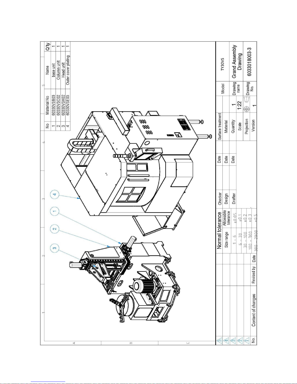
2.3 Assembly Drawing & Machine list ............................................................................... 8
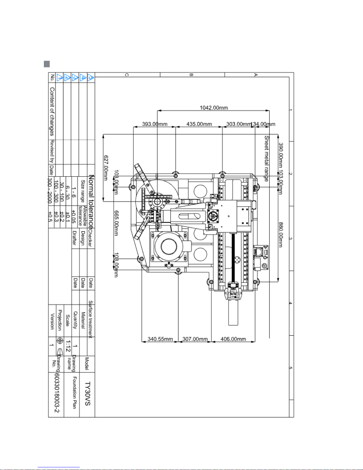
2.4 Foundation Plan ............................................................................................................. 9
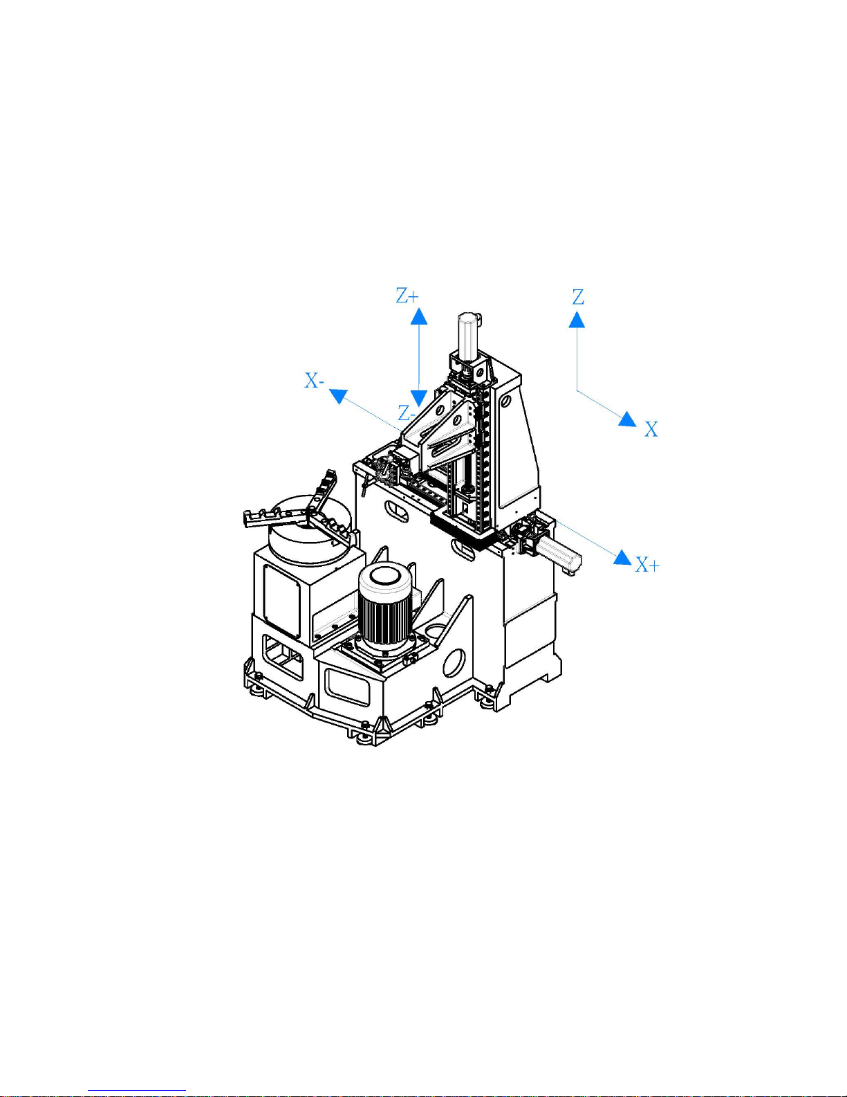
2.5 Mechanical Coordinate System .................................................................................. 10
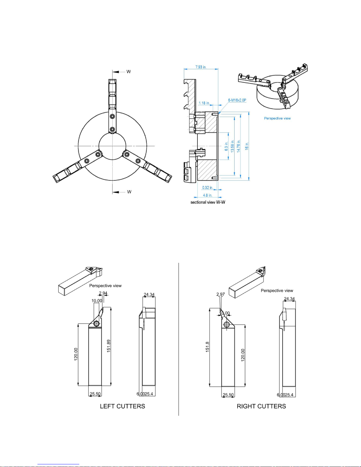
2.6 Jaw Chuck size ............................................................................................................. 10
2.7 Tool Holder Dimension Drawing ................................................................................ 11
3. Move, Store and Install the Machine ................................................................ 11
3.1 Pre-installation Work
3.2 Unload and Moving the Machine ............................................................................... 13
3.3 Installation & Levelling
3.3.1 Machine Installation and Leveling ...................................................................
3.3.2 Install the Peripherals ................................................................................... 16
3.4 Power Requirement ..................................................................................................... 17
3.5 Compressed Air Source ............................................................................................... 18
3.6 Other Objects ............................................................................................................... 18
4. Pre-boot Preparation Works ............................................................................. 19
4.1 Pre-boot Check ............................................................................................................. 19
4.2 Oil-feed and Oil Types ................................................................................................. 20
4.2.1 Machine’s Oil-feed Points ............................................................................. 20
4.2.2 Referenced Machine Oils .............................................................................. 20
4.3 Chips Conveyor System ............................................................................................... 21
5. Machine Maintenance and Tuning ................................................................... 22
5.1 Maintenance Period ..................................................................................................... 22
5.1.1 Maintenance Interpretation .......................................................................... 22
5.1.2 Machine Regular Maintenance Frequency List .......................................... 22
5.1.3 Maintenance Check Sheet ............................................................................. 24
5.2 Soft jaw chuck Mechanism.......................................................................................... 26
5.3 Forced Auto Lubricator ............................................................................................... 26
6. Troubleshooting .................................................................................................. 29
6.1 Machine Troubleshooting ............................................................................................ 29
6.2 Quick-Wear Part List .................................................................................................. 30
7. Machine Parts List ............................................................................................. 31
Page 3

3
1. Safety Notes
1.1 Safety Specification
This machine is equipped with safety devices designed to protect operators from being hurt
or the machine being damaged. Operators should thoroughly read this Manual as well as
undergo the compulsory training programme before operating this Machine.
Ensure there is sufficient space around the Machine to open the electrical-box door for
maintenance/repair and space to allow normal access to and from the machine. Assign
qualified electrical personnel to wire this Machine from the plant power supply.
Do not operate the machine if any safety devices have been damaged or removed.
.
1.2 General Safety Notes
1. If you have any safety queries – do not operate the machine.
2. All maintenance and repairs must be undertaken by skilled and trained personnel..
3. Operator should wear appropriate clothing during operation. Do not wear loose fitting
clothing and remove or cover rings and watches.
4. Operators must use approved personal safety equipment.
5. Do not allow other personnel to stand around the machine while it is operating.
6. Ensure the work area around the machine is free from obstruction.
7. When cleaning the machine or removing machined parts do not climb into the
machine.
8. Keep the work area clean and dry.
9. Do not store or keep flammable or hazardous substances near the machine.
10. Do not try to modify this Machine or method of operation.
11. Keep the observation window clean.
12. This Machine is equipped with three-colour alarm light to indicate the alarm status
(red-danger (push the emergency-stop button), amber-warning (abnormal occurs), and
green-normal in operation).
13. Do not attempt to machine oversize work pieces.
14. Do not leave any article or tool within the work chamber.
Page 4

4
1.3 Notes after Machining Operation Stops
1. Before opening the Access Doors, be sure that the chuck has stopped turning.
2. After the dry-cutting process is complete and before removing the workpiece, be sure
to put on safety gloves (to avoid skin-burn).
1.4 Notes on Handling Abnormal Status
1. Once an abnormal status occurs, press the emergency stop button immediately.
2. Before accessing Machine’s inner space, be sure that the main power supply is off and
the machine is stationary.
3. If in doubt, press the Emergency Stop Button and seek advice.
1.5 Maintenance Safety Notes
1. Before performing maintenance works, shut down main power supply and lock off.
2. Do not leave the machine in an exposed condition and un- attended..
3. After work is completed, do not leave any tool or part in the Machine or on the
operation panel.
4. Clean up the chip tank regularly and wear the correct hand-protection to prevent
allergy or cuts.
5. Keep the observation window clean. If the transparency is blurred, replace it
immediately.
1.5.1 Routine Maintenance
(1) Keep the Machine bed clean.
(2) Tune the indicating gauges (pneumatic and lube oil) to correct positions.
(3) Ensure that lube oil reaches the guide-way.
Page 5
5
1.6 Noise
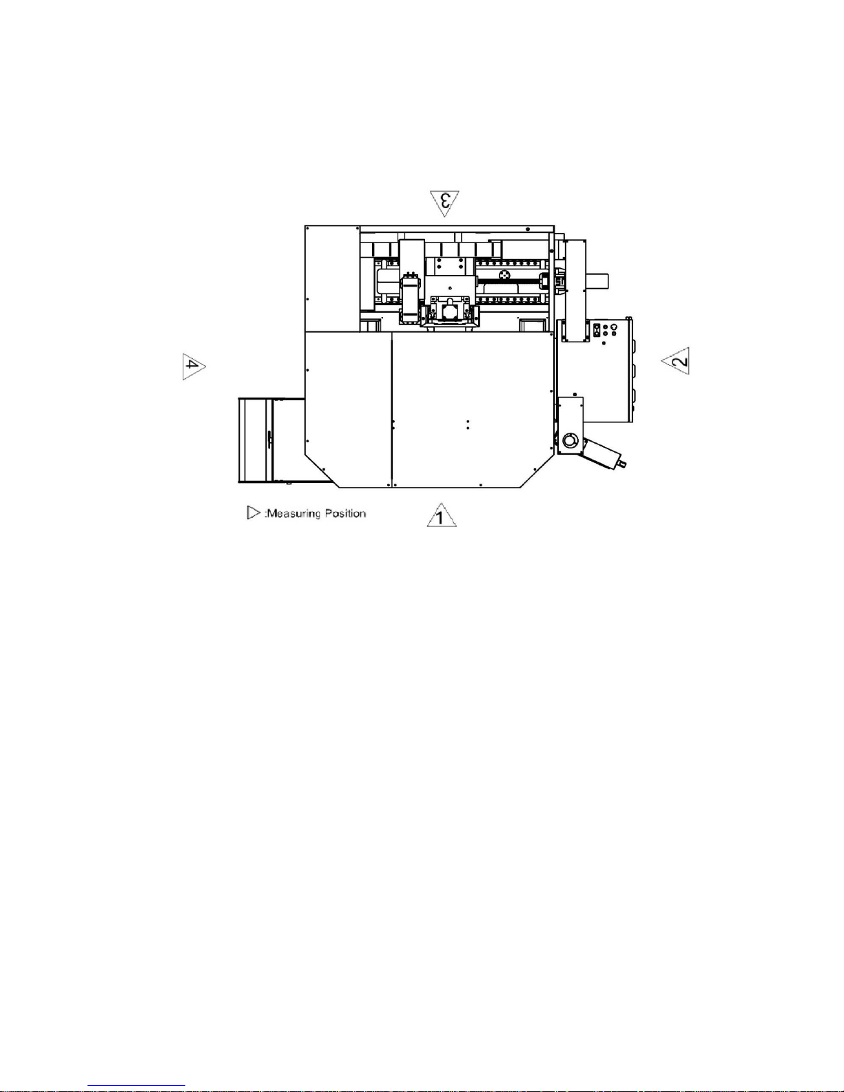
Per ISO/DIS 230-5 Standard, noise of Machine either at stationary or running status should
be lower than 80 dBA. If over this level, inform us immediately to correct the Machine. The
inspection positions are shown in the figure below.
Measurement standard: according to Machinery Directive 98/38/CE Annex I article 1.7.4(f)
specification.
Spindle speed: 80% of the maximum speed value.
Measuring distance: 1m from the machine housing.
Measurement height: 1.6m from the ground
Page 6
6
2. Machine Brief Introduction
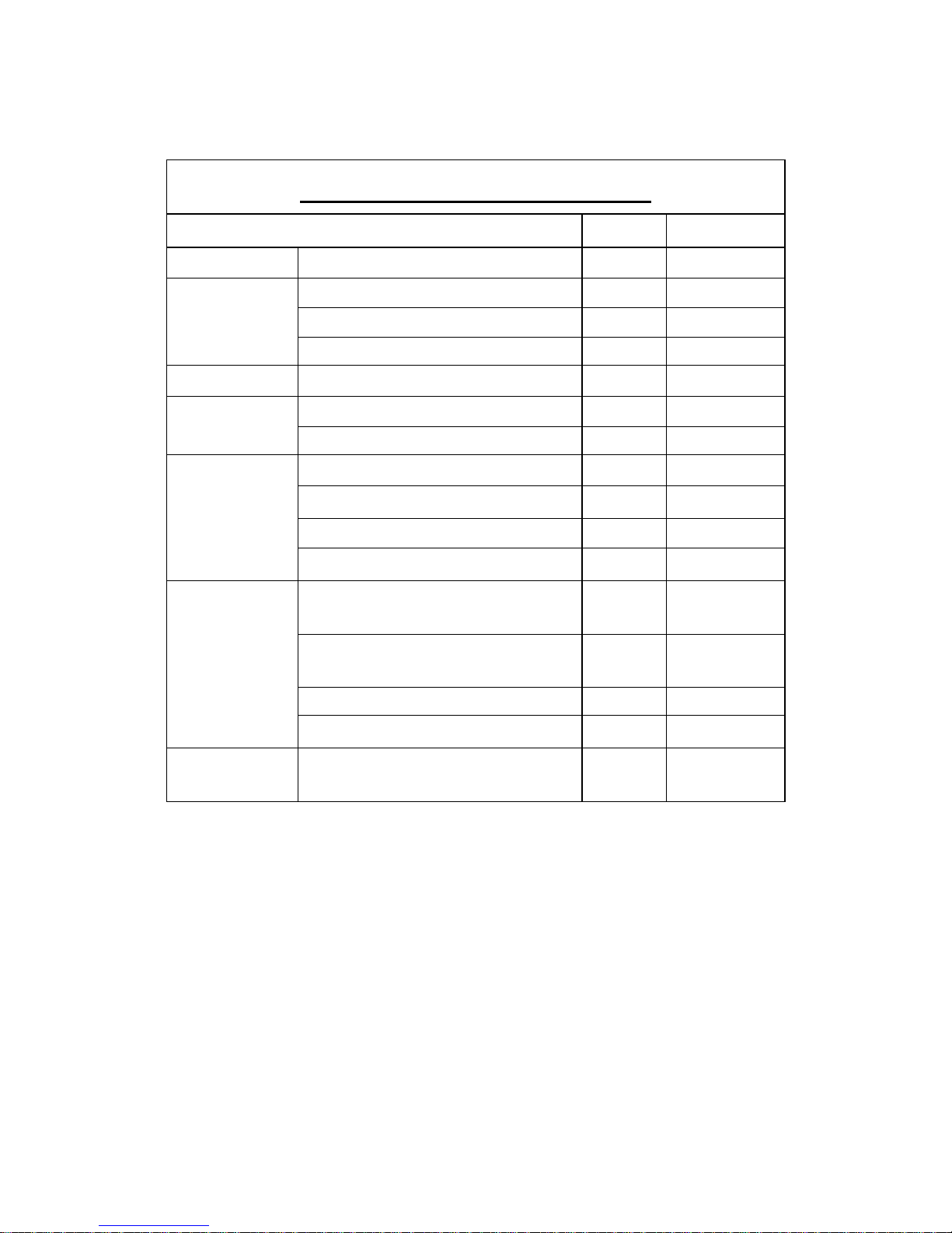
2.1 Mechanical Specification
Standard accessories:
1. Digitising Probe
2. Diamond Cutter
3. USB & Etherent Ports
4. Halogen Work Light
5. Auto Lube
6. Way Covers
7. Chip Tray
8. Tools & Tool Box
9. Four Way Tool Post
TY30-VS SPECIFICATION
Model
Unit
VTL30
Control
Control System
BECKHOFF
Travel
X-axis Travel
mm(inch)
508(20")
Z-axis Travel
mm(inch)
457(18")
Max.Turning Diameter
mm(inch)
762(30")
Table
Jaw Chuck(Manual)with Soft Jaw
inch
16" - 3
Distance
Distance from Spindle end to Table
mm(inch)
0-457(0~18")
Spindle Nose Taper / Tool
A2-6
Spindle
Spindle Speed
rpm
60~1000
Spindle Type
Belt Drive
Spindle Motor
KW(HP)
7.6(10HP)/4P
2 axes Servo Motors (X/Z)
KW
1.3
Feed
X-axis Rapid Traverse
M/min
10 / Direct
Drive
Z-axis Rapid Traverse
M/min
10 / Direct
Drive
Cutting Feedrate
M/min
10
Min. Input Unit
mm/min
0.001
Installation
Requirements
Weight (about)
t
2
Page 7
7
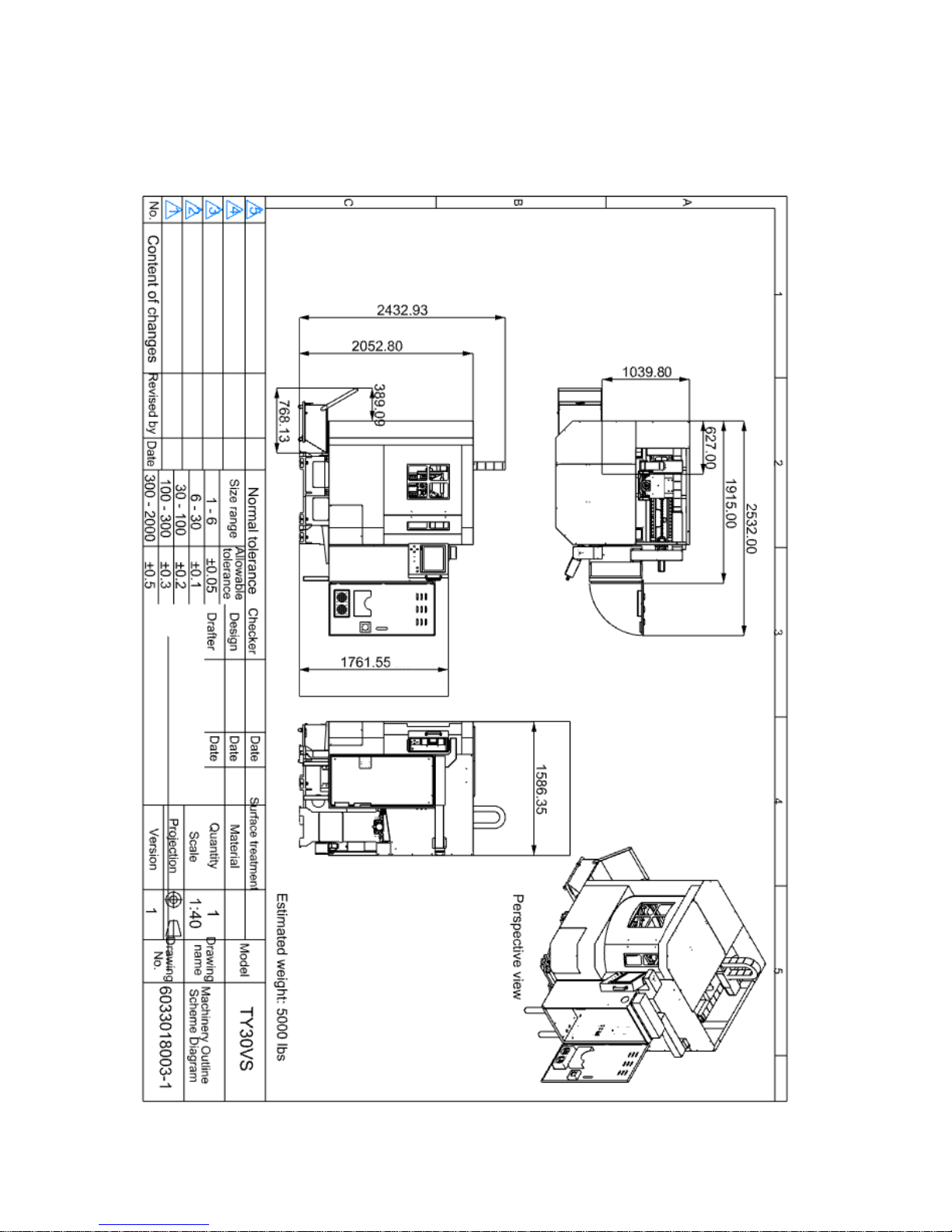
2.2 Machinery Outline Scheme Diagram
Page 8
8
2.3 Assembly Drawing & Machine list
Page 9
9
2.4 Foundation Plan
Page 10
10
2.5 Mechanical Coordinate System
Axis-definitions are expressed in below:
X-axis: X-axis is the direction that tool post moves right/left; (+) for right movement and (-)
for left one.
Z-axis: Z-axis is the direction that tool post moves up/down; (+) for up movement and (-)
for down one. tool post
Page 11
11
2.6 Jaw Chuck size
2.7 Tool Holder Dimension Drawing
Page 12

12
3. Move, Store and Install the Machine
3.1 Pre-installation Preparation Works
1. Power source: required power supply specification:
Power
Voltage
Frequency
Phase
Specification
220V
60 HZ
3+Neutral+Earth
2. Pneumatic - air pressure used to clean up spindle, cool down cutting is 5 ~ 7 KG/CM
2
,
at least 90 NL/min of supply.
3. Oils: feed in required oils before starting this Machine:
Purpose
Product name
Viscosity (40°C)
Capacity
Remark
Lube oil
Guide-way oil
61.2 ~ 74.8
2L
ISO VG68,R-68, K68
4. Precision measuring equipment:
1. 0.02mm/M level meter, at least two pieces.
2. Gauge-carried magnetic seat 1/100, 2/1000mm, one or more set each.
3. One granite right-angle ruler.
5. Space requirement:
To plan for Machine layout space, reserve sufficient space for the
operation/maintenance and access to and from the machine.
Page 13
13
3.2 Unload and Moving the Machine
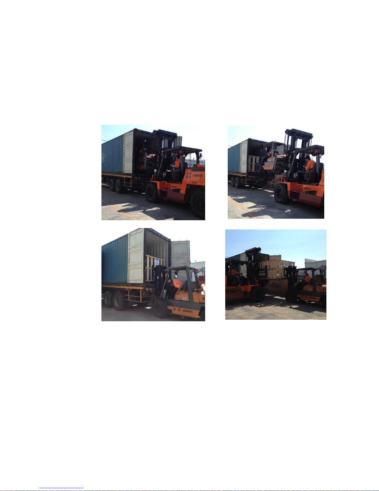
1. Unload the Machine package: (refer to the pictures below)
The Machine is mounted on a stillage, use forklift to unload the package from
container.
Unload the Machine as shown in the pictures:
Page 14
14
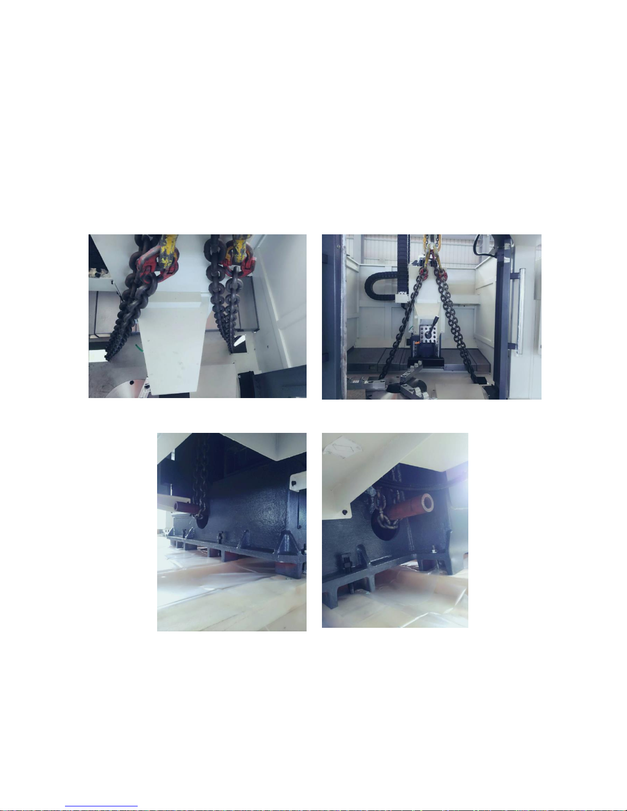
(2) Removing the machine from the pallet:
a. Remove the 2- covers in front of X axis cover.
Insert a steel bar inside the machine base. (See the figure below)
b. Pass a chain through the 2 openings and loop the chain around the steel bar
from both side of the machine.
c. Then the machine can be lifted.
d. Suitable protection should be used to prevent the chains damaging the paint
Finish of the machine.
.
Page 15
15
3.3 Installation and Levelling
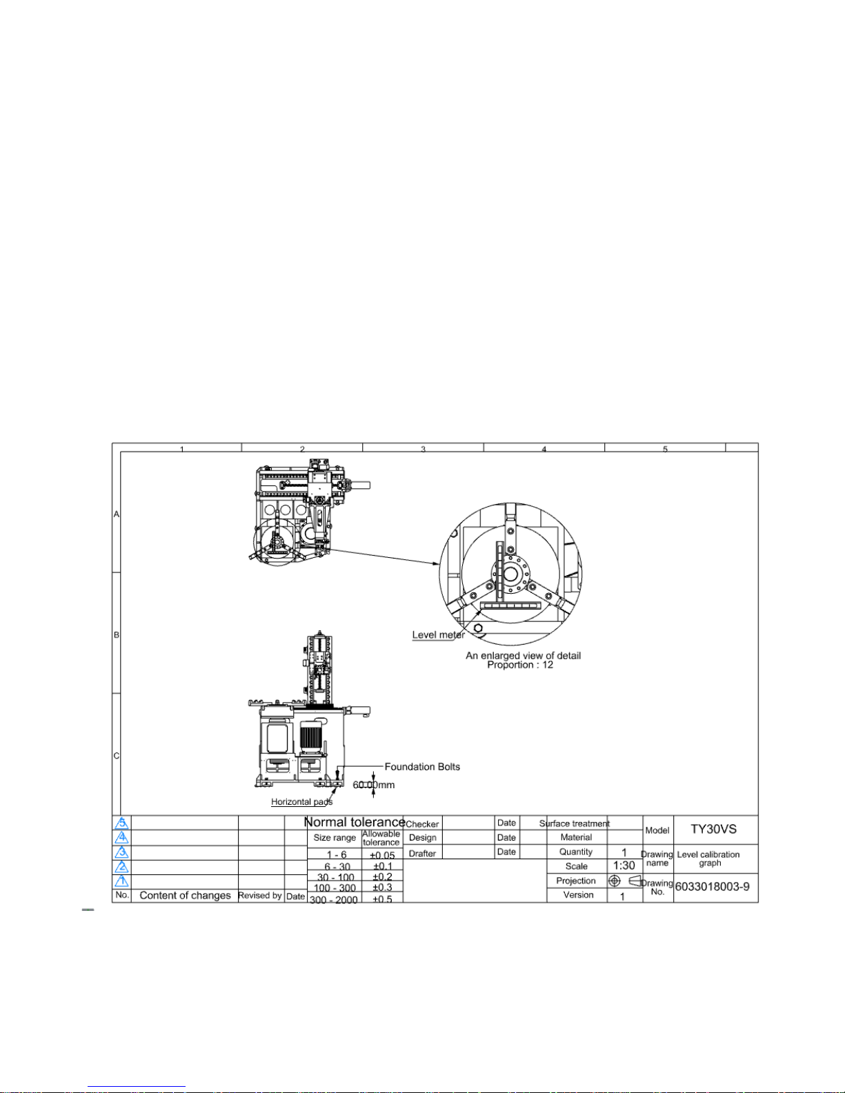
3.3.1.Machine leveling adjustment
(1) Use the leveler 0.02 mm/m on the center of the chuck,fix the leveler on the X
axis direction and manualy turn the chuck, adjust the level of X axis until the air
bubble in the leveler is centered. Repeat for Z axis.
Page 16

16
3.3.2 Install the Peripherals
Installing steps of peripherals
No.
Steps
Explanation
1
Compressed air
source
Connect air supply to input point.
2
Filling track
lubricants
Fill lubrication system..
3
Remove the mount
block
Remove the mount blocks in X- & Z-axis; don’t remove the
wooden block that supports the spindle head.
4
Mount and install
the wiring lines
Follow the wire numbers connecting and mounting the
dismantled wires/pipes.
5
Electric control
After checking the electric control lines, connect them.
6
Turn on power to
make test run
a. Certify the correctness of power phases.
b. Certify the correctness of motor turning direction.
c. Check if pipe connectors are connected correctly and
locked tight; mechanism locations are correct
(mechanism should be located at respective location
normally).
d. Lift the tool post head; take out the supporting pads.
7
Certify track
lubrication
Check if the lube system feeds lube oil? Are two lube oils
distributed properly?
8
Clean
Clean the anti-rust oil on jaw chuck & tool post; clean up
dust on Machine and wipe it clean.
9
Commissioning
a. First, manually return Machine’s three axes back to
HOME point manually in slow speed.
b. Return the two axes back to HOME point by 100% fast
speed; certify if the HOME points are same.
c. Check if stroke of each axis follows the set one? If
over-stroke is effective?
d. Follow the attached parameter table to check if
controller’s display meets the parameter table or not?
e. Are the spinning directions and speed of positive/reverse
turns normal?
10
Warm-up run
During running, follow the precision inspection table to
make commissioning run.
Page 17
17
3.4 Power Requirement
. Power and ground
Main power input 3 phase 415V with Neutral and earth
32 Amps per phase
Single Phase Not Required
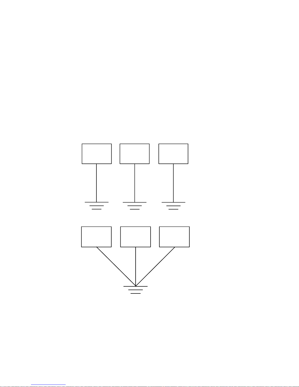
7. Notes on installing power source and grounding work
(1) Do not co-use power cable with other machines. Provide an independent power
line for this Machine.
(4) Power cable’s external terminals must be protected by a fuse or breaker.
(5) The grounding resistance should be less than 50Ω.
(6) Grounding line color is yellow-green.
Graphic demonstration of machine grounding:
Fig. 1: Single set grounding
Fig. 2: Multi sets grounding
Machine 1
Machine 2
Machine 3
Machine 1
Machine 2
Machine 3
Page 18

18
3.5 Compressed Air Source
1. Use clean air source.
2. Confirm that the air source can provide necessary air flow-rate.
3. Air pressure should exceed 6 kg/cm2.
4. Arrangement of reserved pipelines:
(1) Compressed air must be filtered and be clean and dry (dew point, 6 kgf/cm
2
,
10°C).
(2) Supply or compressed air must satisfy Machine’s consumption requirement (1-hp
air compressor that supplies 9 0NL/min is approx. enough).
(3) Refer to the drawing below for the input points of compressed air and power
supply.
The compressed air fast-connector size is 9.525 mm (3/8 in.).
.
3.6 Other Objects
Clean Utensils Requirement Table
Name
Specification/Quantity
Remark
Kerosene
1L
Used to clean the Machine
Non-volatile cleaning agents
0.5L
Used to clean the Machine
Rag
10 pieces
Used to clean the Machine
Fur brush
1 piece
Used to clean the Machine
Page 19

19
4. Pre-boot Preparation Works
4.1 Pre-boot Check
In order to ensure the safety of operators and Machine, check the following items before
booting
.
1. Check if oil in the lube oil tank is sufficient?
2. Ensure that space around the Machine and control system is clear.
3. Ensure that every panel and door is closed.
4. Ensure that all control switches are at good condition.
5. Is there anyone in the Machine’s danger area?
6. Does operator wear suitable clothing and correct personal protection equipment
7. Clean up residual water in the air pressure regulators filter.
8.. Check if compressed air, lubrication, hydraulic and cooling system pipelines are
secure.
9. Check and make sure that all safety devices are operating.
14. Certify that toolsand workpiece is secure..
Page 20
20
4.2 Oil-feed and Oil Types
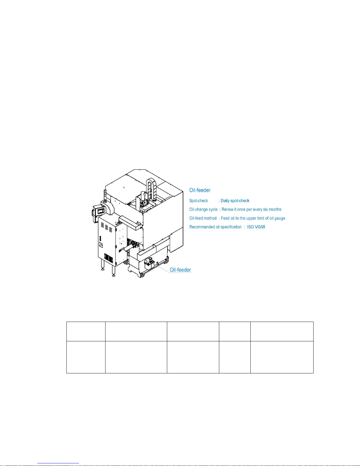
1. The Machine two axis guide-ways and ball screw are under forced-lubrication
operation with auto oil-feeding.
2. Prior to booting, check if lube oil is sufficient.
3. Always use the correct lube oil; incorrect oil will reduce Machine’s lifetime and may
cause malfunction.
4. Lube oil flow-rate is adjusted prior to delivery. Unless the loop is clogged or faulty, do
not adjust it.
4.2.1 Machine’s Oil-feed Points
The following diagram presents the Machine’s oil-feed points. While feeding or replacing
oil, do it at the specified oil-feed points (see the recommended oil list shown in next page).
4.2.2 Referenced Machine Oils
Recommended oil list:
Position
Spot-check/oil-change
cycle
Method
Oil tank
capacity
(Unit: L)
Recommended oil
specification
Oil-feeder
Daily spot-check
When lube-oil-low
alarm appears
Renew it once per
every six months
Feed oil to the upper
limit of oil gauge
2
ISO VG68
MOBIL, DTE 26
SHELL, TELLUS 68
ESSO, TERESSO 68
CASTROL, ALPHASP 68
Page 21
21
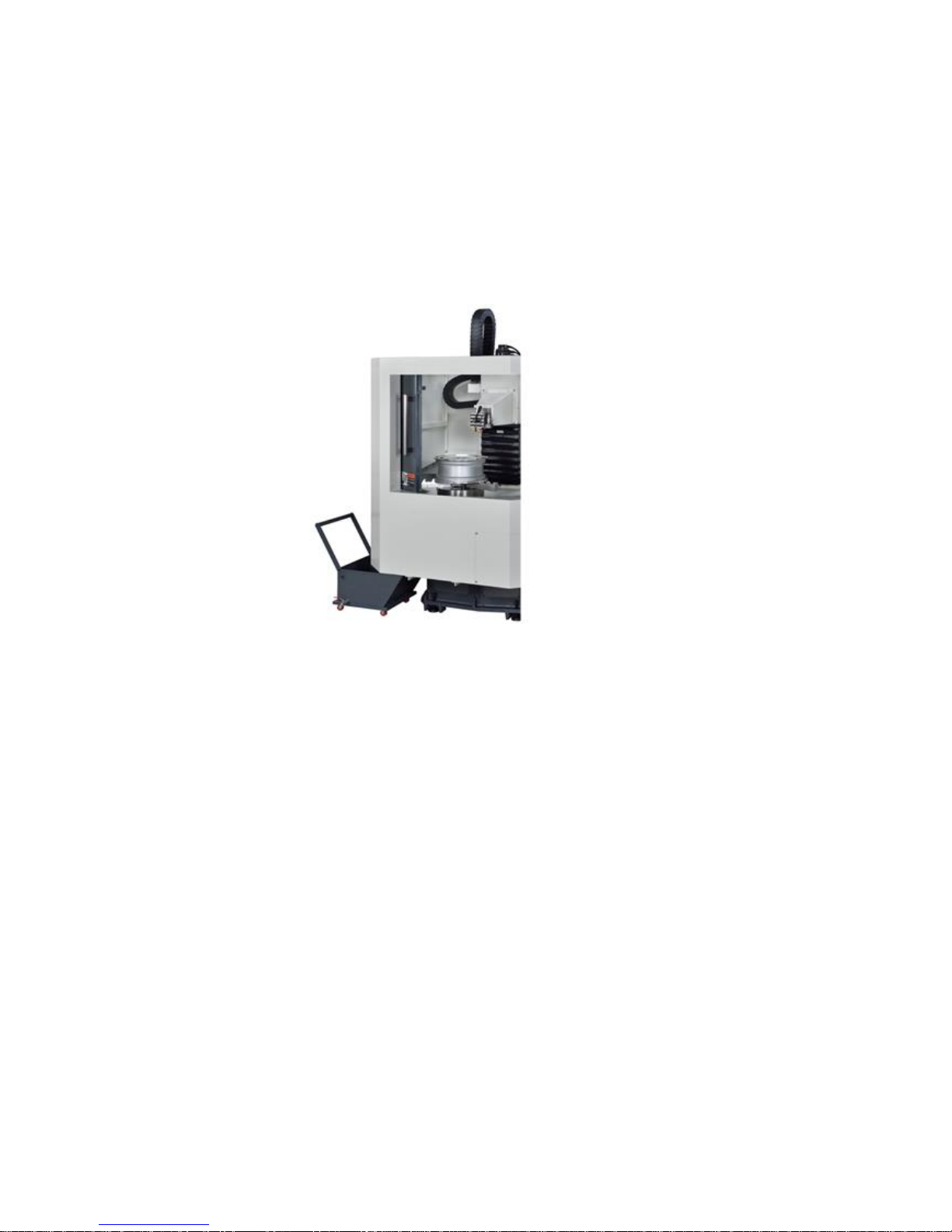
4.3 Chips Removal
Manually clean the chips, sweep the chips to the front left corner where the chip tank located.
Page 22
22
5. Machine Maintenance and Tuning
5.1 Maintenance Period
5.1.1 Maintenance Interpretation
Regular maintenance can extend Machine’s operation lifetime and maintain its working
efficiency.
In this section we’ll provide the maintenance methods of systems/units and suggested
maintenance schedule. When performing maintenance, substantially obey the methods/time
presented in this section.
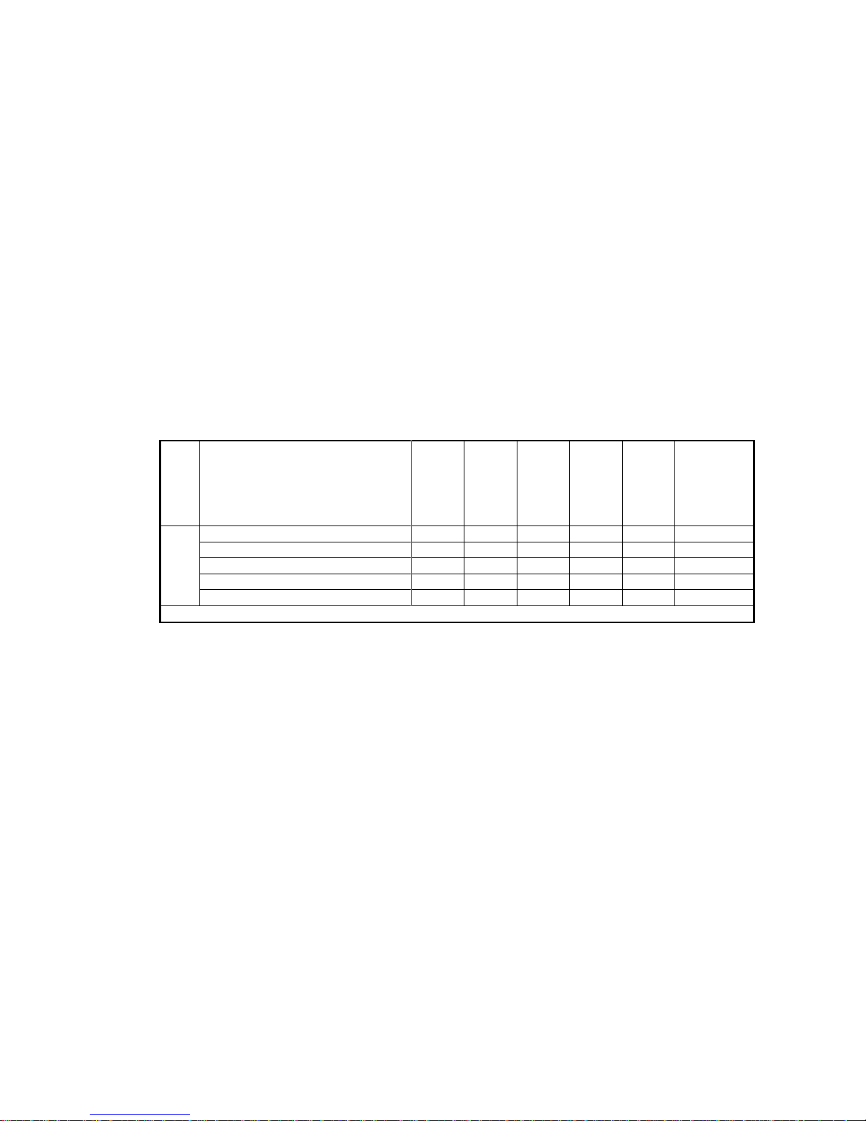
5.1.2 Machine Regular Maintenance Frequency List
Machine regular maintenance frequency list (1/3)
Maintenance work content
Daily
maintenance
Weekly
maintenance
Monthly
maintenance
Half year
maintenance
Yearly
maintenance
Remark
Pneumatic
system
Check pneumatic air pipelines
D W M H Y Check the air pressure
D W M H Y
Page 23
23
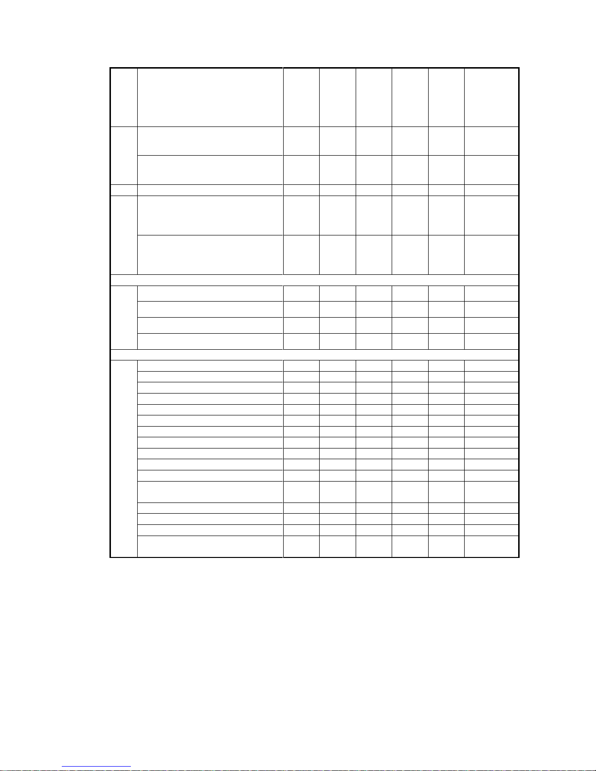
Machine regular maintenance frequency list (3/3)
Maintenance work content
Daily
maintenance
Weekly
maintenance
Monthly
maintenance
Half year
maintenance
Yearly
maintenance
Remark
Oil-feeder
Check lube oil level
D W M H Y Check oil-feed pressure
W M H Y
Operation panel
Check indicators on panel
D W M H Y Check switches on panel
D W M H Y
Electrical box
Clean up heat exchanger filter
W M H Y Clean electrical box
M H Y Clean electrical components
M H Y Lock up devices in electric-box
M H Y
Other
Clear jaw chuck chips
D W M H Y Clear machine chips
D W M H Y Clean up chips in X-, Z-axis cover
D W M H Y X-axis cover oiling
W M H Y Locking tool holder
D W M H Y Clean up chips on tool holder
D W M H Y Check two axes track
H Y Check two axes screw
H Y Clean up chips on anchor bolts
M H Y Anchor bolts oiling
M H Y Check the tightness of anchor bolts
H Y
Clean up chips in flexible shielding
tube
M H Y
Check pipeline in shielding tube
M H Y Check flexible shielding tube
H Y Clean up chips on top of column
D W M H Y
Discharge recycled lube oil from
two-axis
W M H Y
Page 24
24
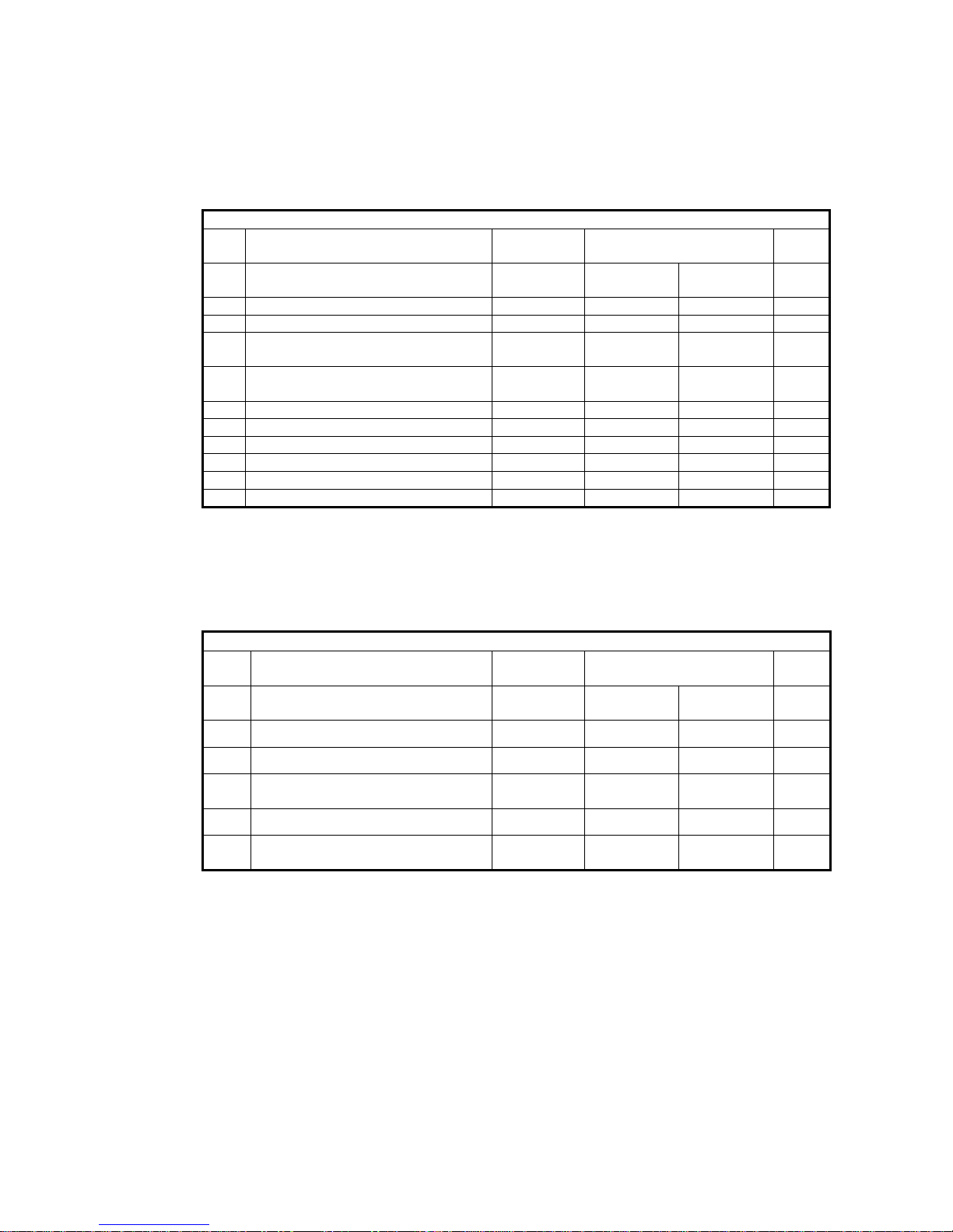
5.1.3 Maintenance Check Sheet
1. Daily maintenance sheet
Model/Machine No.:
/
Maintenance date:
By:
Confirmed:
Daily maintenance
Item
Maintenance work
Maintenance
type
Checked/confirmed
Remark
01
Check air pressure of air-pressure
regulator
DWMHY
□Accomplished
□Not performed
02
Clean up chips in chips tank
DWMHY
□Accomplished
□Not performed
03
Check if oil in oil-feeder is sufficient
DWMHY
□Accomplished
□Not performed
04
Check if the indicators on the board
are all normal
DWMHY
□Accomplished
□Not performed
05
Check if the switches on the board are
all normal
DWMHY
□Accomplished
□Not performed
06
Clean up chips on jaw chuck
DWMHY
□Accomplished
□Not performed
07
Clean up chips in machine
DWMHY
□Accomplished
□Not performed
08
Clean up chips in X-, Z-axis cover
DWMHY
□Accomplished
□Not performed
09
Locking tool holder and pull handle
DWMHY
□Accomplished
□Not performed
10
Clean up chips sticking on tool holder
DWMHY
□Accomplished
□Not performed
11
Clean up chips on column
DWMHY
□Accomplished
□Not performed
2. Weekly maintenance sheet
Model/Machine No.:
/
Maintenance date:
By:
Confirmed:
Weekly maintenance
Item
Maintenance work
Maintenance
type
Checked/confirmed
Remark
12
Check if oil-feeding pressure of
oil-feeder is normal
WMHY
□Accomplished
□Not performed
13
Clean up dust on electric-box fan
WMHY
□Accomplished
□Not performed
14
Jaw chuck surface antirust-oiling
WMHY
□Accomplished
□Not performed
15
Antirust-oiling and lubrication of Xprotection covers
WMHY
□Accomplished
□Not performed
16
Tool holder antirust-oiling
WMHY
□Accomplished
□Not performed
17
Discharge recycled lube oil from
three-axis
WMHY
□Accomplished
□Not performed
Page 25
25
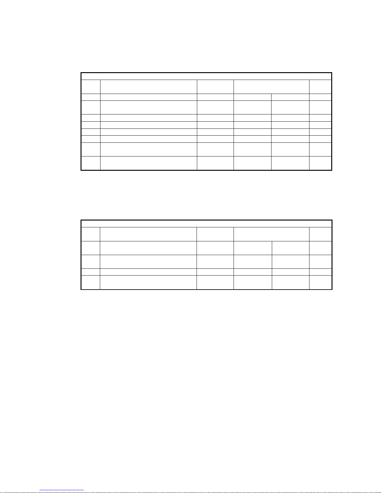
3. Monthly maintenance sheet
Model/Machine No.:
/
Maintenance date:
By:
Confirmed:
Monthly maintenance
Item
Maintenance work
Maintenance
type
Checked/confirmed
Remark
18
Clean fan filter
MHY
□Accomplished
□Not performed
19
Clean up dust and foreign matter in
electrical-box
MHY
□Accomplished
□Not performed
20
Clean up dust on electric devices
MHY
□Accomplished
□Not performed
21
Adjust and lock up electric devices
MHY
□Accomplished
□Not performed
22
Clean up chips on anchor bolts
MHY
□Accomplished
□Not performed
23
Anchor bolts antirust-oiling
MHY
□Accomplished
□Not performed
24
Clean up chips in flexible shielding
tube
MHY
□Accomplished
□Not performed
25
Check if the piping layout inside
shield tube is normal
MHY
□Accomplished
□Not performed
4. Yearly maintenance sheet
Model/Machine No.:
/
Maintenance date:
By:
Confirmed:
Yearly maintenance
Item
Maintenance work
Maintenance
type
Checked/confirmed
Remark
26
Check if the tracks of two-axis are
normal
HY
□Accomplished
□Not performed
27
Check if thescrews of two-axis are
normal
HY
□Accomplished
□Not performed
28
Check if anchor bolts are normal
HY
□Accomplished
□Not performed
29
Check if flexible shielding tube is
normal
HY
□Accomplished
□Not performed
Page 26
26
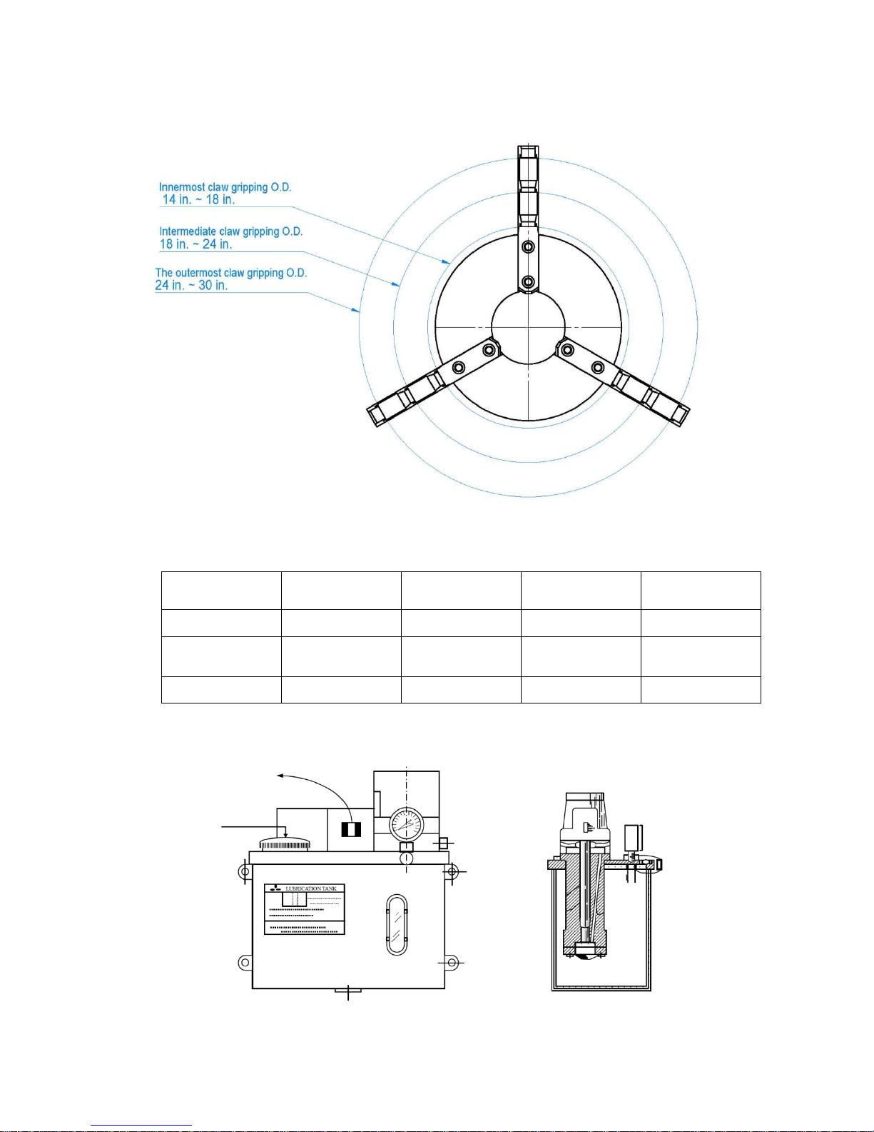
5.2 Soft jaw chuck Mechanism
5.3 Forced Auto Lubricator
Electric Lubricator specification
Type
Lubricating
time
Intermediate
time
Maximum
flow-rate
Maximum
pressure
JY19B
1-99 sec.
1-99 min.
180 c.c/min
8 kg/cm
2
Floating-ball
switch
Oil tank capacity
Three-phase
voltage
Motor output
power
Connector
diameter
2 L
220V/0.3A
51 W
PT 1/8
Graphical demonstration:
Manually start
switch
Oil-feed
opening
Page 27
27
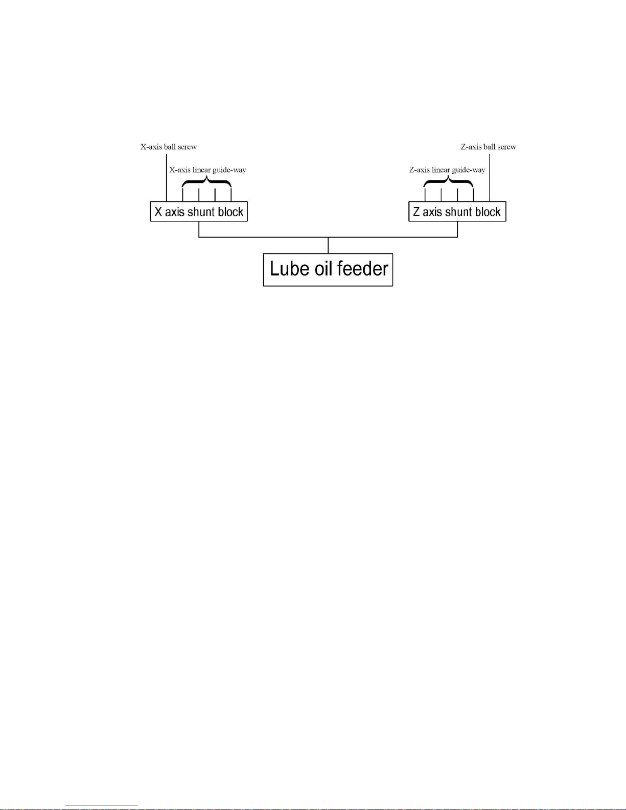
1. Lube oil unit loop
2. Oil-feeding method and feeding adjustment
This Machine applies forced oil-feeding. Oil supply may be operated automatically or
manually.
(1) Manual oil feeding: after pressing the start button, pump motor runs to feed oil out;
release the button to stop pump.
(2) Auto oil feeding: when Machine power is on, oil feeder is under oil-feeding status;
it follows the set running/stop time to feed oil automatically.
(3) Oil-output point: each oil-output point applies the volume-distribution valve; each
output point follows the designed oil-output flow-rate using different distribution
valve.
3. Note
(1) This Machine is a fully automatic model. It is equipped with floating switch and
auto-alarm buzzer; once oil amount is in short, alarm indicator is lit automatically,
reminding operator to feed-in oil. Alarm line is connected to CNC controller; if oil
amount or pressure is insufficient, Machine cannot be started in CNC AUTO mode;
alarm displays.
(2) At least clean filter once per year.
(3) Check Daily if oil amount is sufficient.
Page 28

28
4. Troubleshooting of lubrication unit
Item
Fault status
Reason
Troubleshooting method
1
Oil output fails
to output oil
1. Pipeline is clogged.
2. Lube oil viscosity is too high.
3. Filter net is clogged.
4. Oil amount is insufficient.
5. Floating switch is fault.
6. Check valve is clogged.
7. Pump parts fault.
8. Pipe leaks.
1. Clean up or replace pipeline.
2. Change to approvedoil.
3. Remove clogging.
4. Feed oil.
5. Replace.
6. Remove clogging.
7. Repair.
8. Replace pipeline.
2
Alarm appears
1. Pressure switch is
short-circuited.
2. Pipe leaks.
3. Pumping pressure is not
enough.
1. Replace pressure switch or
cable.
2. Replace pipeline.
3. Repair pump.
4. Replace pump.
3
Oil-feeding
flow-rate is
wrong
1. Component parts are worn
2. Oil seal is leaking.
1. Replace to other model.
2. Replace.
Page 29

29
6. Troubleshooting
6.1 Machine Troubleshooting
Item
Fault reason
Factor
Handling method
1
X-axis shakes
1. Lack of oil.
2. Wrong oil applied.
3. Oil flow-rate.
4. Level error is too big.
5. Noise in operation.
1. Renew or supplement oil.
2. Use SHELL R68 guide-way oil.
3. Noise is shown; need to be replaced.
4. Re-adjust level.
5. Track lubrication is abnormal; check the
lubrication system.
2
X-&Z-axis
won’t move
1. Fuse is burnt.
2. AL trips.
3. Touch to the limit.
4. Operation fault.
5. Wire broken
6. Bearing is stuck.
7. Screw faults.
8. Motor is heated.
9. Motor won’t run.
1. Replace.
2. Record the fault signal; contact related entity to
handle it.
3. Be careful.
4. Contact related entity to handle it.
5. Check if related system/parts fault?
6. Replace.
7. Replace.
8. Check motor load, wire connectors and
overload protection relay; clean up motor
external surface.
9. Replace.
3
X-axis, Z-axis is
not lubricated
1. Fuse is burnt.
2. Thermo-timer trips.
3. Wire broken.
4. Electric Lubricator
5. Filter or Oil-hole outlet is stuck.
1. Replace.
2. Check if there is any other reason that causes
the trip.
3. Contact the service personnel to handle it.
4. Replace.
5. Shutdown; clean the filter & oil-hole.
4
Spindle cannot
run
1. Fuse is burnt.
2. Thermo-timer trips.
3. Wire broken.
4. Motor malfunctions.
5. Spindle bearings fault.
1. Check if parts are disorder?
2. Check if parts are disorder?
3. Check if parts are disorder?
4. Contact the service entity to handle it.
5. Contact the service entity to handle it.
5
X-&Z-axis
speed is
abnormal
1. Guide-way is not oil-lubed.
2. Motor malfunctions.
1. Timely add lube oil.
2. Contact the service entity to handle it.
Page 30
30
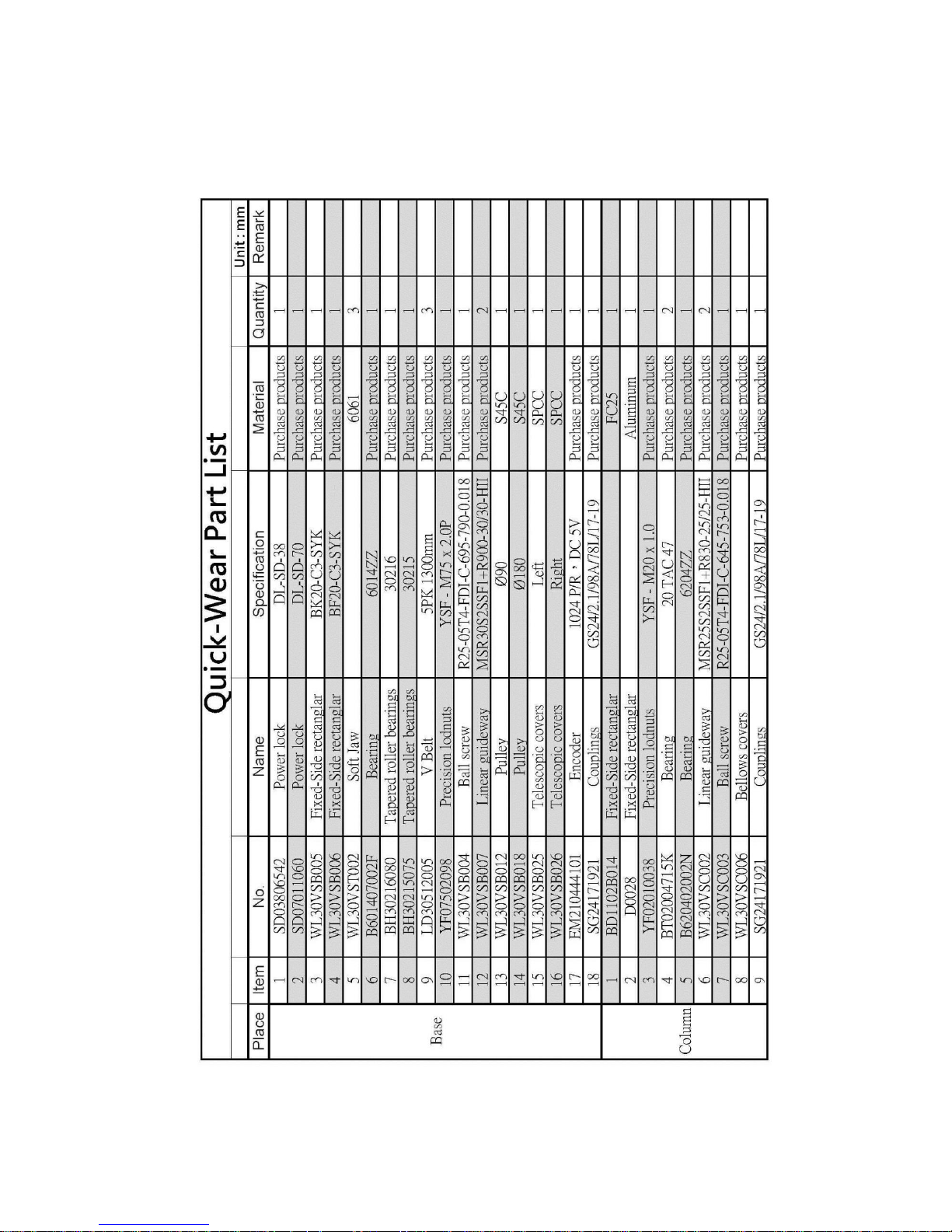
6.2 Quick-Wear Part List
Page 31
31
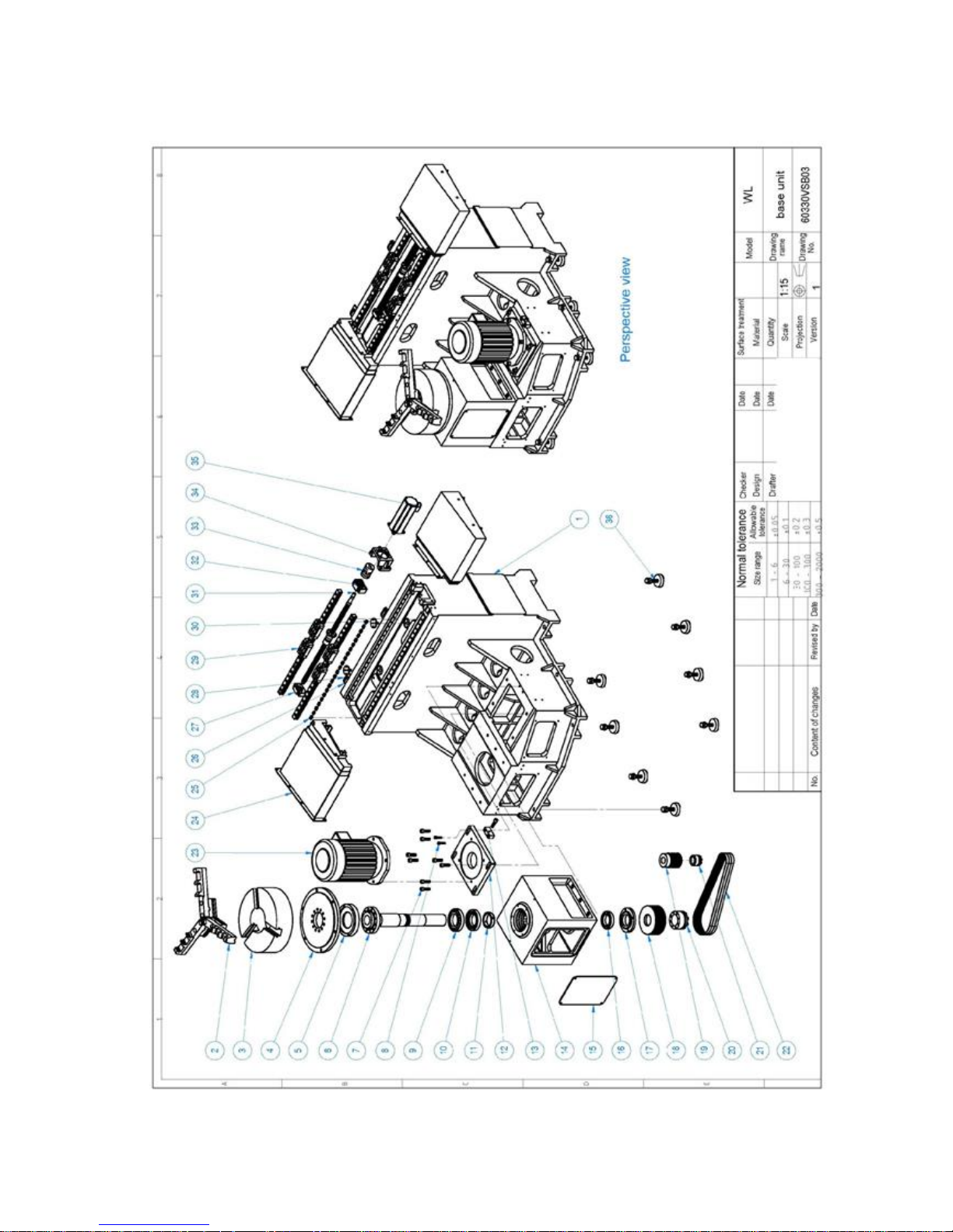
7. Machine Parts List
Page 32

32
No.
Drawing No.
Name
Specification
Material
Quantity
1
WL30VSB001A
Base
FC25
1 2 WL30VST002A
Soft Jaw
6061
3 3 WL30VST001
Chuck
SK-16
Purchase products
1 4 WL30VSB029
Chuck adapter plate
S45C
1 5 WL30VSB021
Spindle the front cover
SS41
1 6 WL30VSB022
Principal axis
S45C
1 7 M14
Hex socket cap screws
M14x50
Purchase products
9 8 M10
Hex socket cap screws
M10x40
Purchase products
2 9 BH30216080
Tapered roller bearings
30216
Purchase products
1
10
BH30215075
Tapered roller bearings
30215
Purchase products
1
11
YF04015058
Precision lodnuts
YSF
Purchase products
1
12
WL30VSB011
Motor adjustment plate
SS41
1
13
SV0850H022
Adjustment Pads
SS41
1
14
WL30VSB019
Headstock
FC25
1
15
WL30VSB024
Spindle cover plate
SS41
1
16
B601407002
Bearing
6014
Purchase products
1
17
WL30VSB020
Bearing gland
SS41
1
18
WL30VSB018
Pulley
S45C
1
19
WL30VSB012
Pulley
S45C
1
20
SD07011060
Power lock
DL-SD-70
Purchase products
1
Page 33
33
No.
Drawing No.
Name
Specification
Material
Quantity
20
SD07011060
Power lock
DL-SD-70
Purchase products
1
21
SD03806542
Power lock
DL-SD-38
Purchase products
1
22
LD30512005
V Belt
5PK 1300mm
Purchase products
3
23
EM00210004
Induction Motor
10HP/4P
Purchase products
1
24
WL30VSB025
Telescopic covers
Purchase products
1
25
KT10505520
T1-oblique block
Purchase products
44
26
NC0020
Hit the block
Purchase products
2
27
WL30VSB006
Linear Guides support base
BF20
Purchase products
1
28
WL30VSEC006
Hit the block fixing plate
SS41
2
29
WL30VSB007
Linear guideway
MSR30
Purchase products
2
30
WL30VSB024
Drain oil fittings
SS41
2
31
WL30VSB004
Ball screw
Purchase products
1
32
WL30VSB005
Linear Guides support base
BK20
Purchase products
1
33
SG24171921
Couplings
Purchase products
1
34
WL30VSB023
Motor mount
SS41
1
35
AM8043
Servomotor
Purchase products
1
36
BD1102B902
Foundation Bolts
Purchase products
8
Page 34
34
Page 35

35
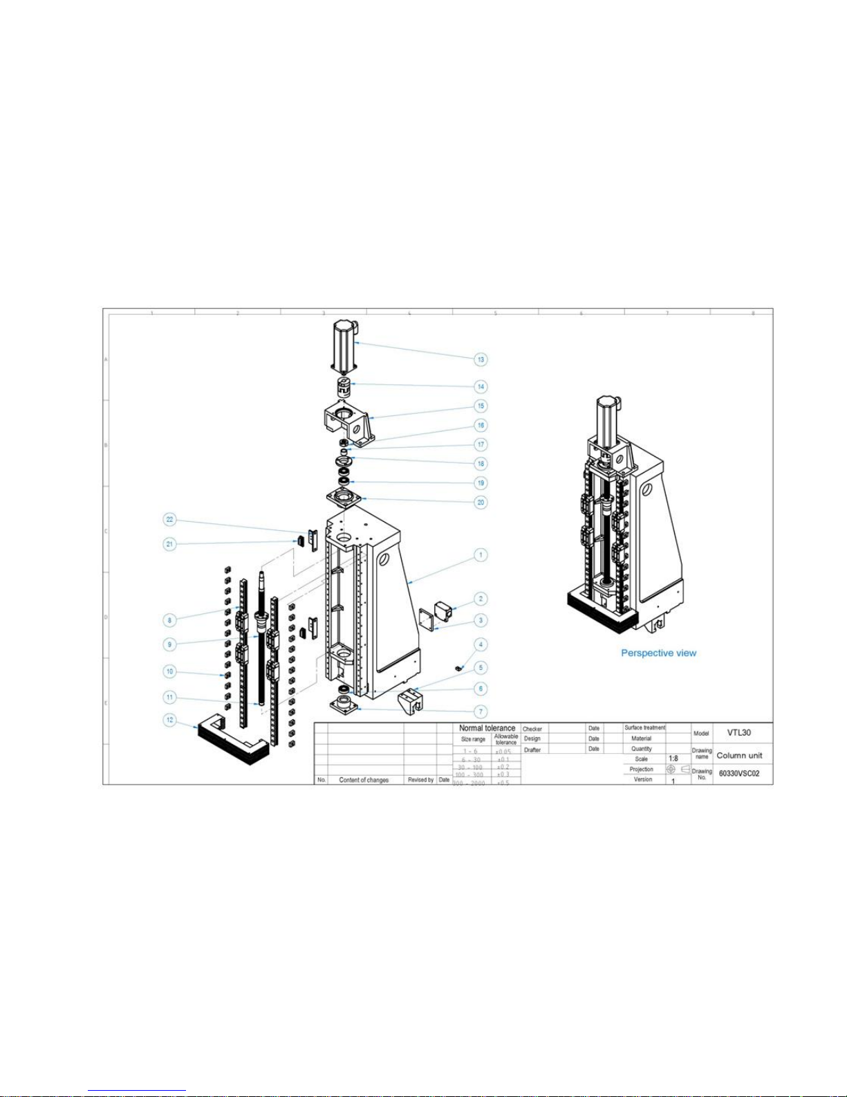
No.
Drawing No.
Name
Specification
Material
Quantity
1
WL30VSC001A
Column
FC25
1 2 Z841011
limit switch
Purchase products
1 3 WL30VSEC005
limit switch fixed plate
SS41
1 4 KT10505520
T1-oblique block
Purchase products
4 5 WL30VSC004
Nut seat
SS41
1 6 B620402002
TAC-Bearing
Purchase products
1 7 BD1102B014
Fixed-Side rectanglar
FC25
1 8 WL30VSC002
Linear guideway
MSR25
Purchase products
2 9 WL30VSC003
Ball screw
Purchase products
1
10
XE00M05BE0
Briquetting
Purchase products
28
11
TB01020
C-type buckle
Purchase products
1
12
WL30VSC006
Bellow Covers
Purchase products
1
13
AM8043
Servomotor
Purchase products
1
14
SG24171921
Couplings
Purchase products
1
15
WL30VSC010
Motor mount
SS41
1
16
YF02015038
Precision Locknuts
YSF-M20X1.5
Purchase products
1
17
BD1101B006
Spacer ring
S45C
1
18
C0090
Bearing gland
Aluminum
1
19
BT02004715
TAC-Bearing
20TAC47
Purchase products
2
20
D0028
Fixed-Side rectanglar
Aluminum
1
21
NC0020
Hit the block
Purchase products
2
22
WL30VSEC006
Hit the block fixing plate
SS41
2
Page 36
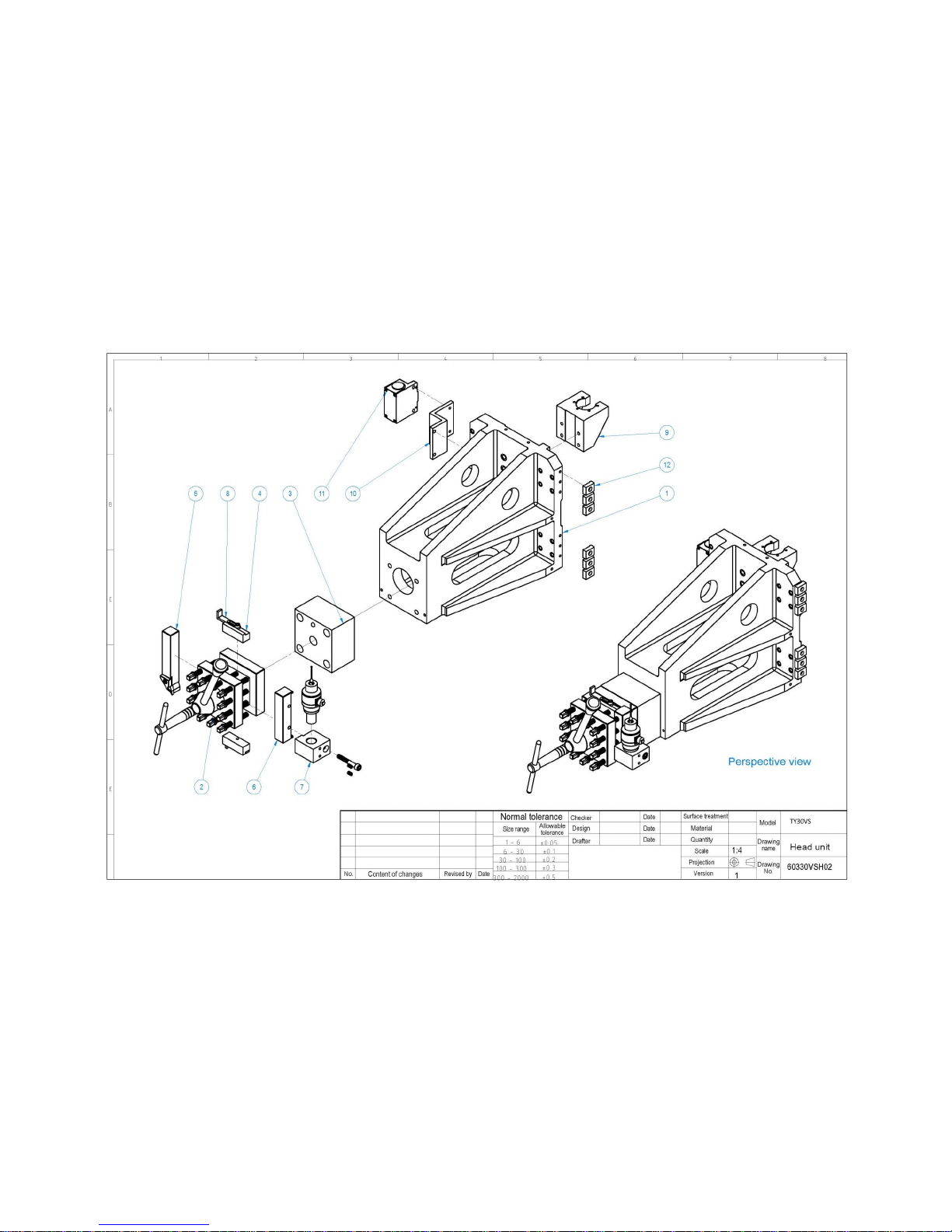
36
Page 37

37
No.
Drawing No.
Name
Material
Quantity
1
WL30VSH001
Z-axis slide
SS41
1 2 WL30VSH002
Quartet turret
Purchase products
1 3 WL30VSH003A
Turret seat
SS41
1 4 WL30VSH013
Tool mounting block
SS41
2 5 WL30VSH014
Cutters
Purchase products
1 6 WL30VSH018
Probe handle
SS41
1 7 WL30VSH021
Probe socket
SS41
1 8 WL30VSH023
Tool positioning sheet metal
SS41
2 9 WL30VSC004
Nut seat
SS41
1
10
WL30VSEC005
Z-axis limit switch fixed plate
SS41
1
11
Z841011
limit switch
Purchase products
1
12
XE00M05BE0
Briquetting
Purchase products
6
 Loading...