


Declaration
TRW Automotive, Parts & Service reserves the right to change the contents of this manual at any time without
notice. The information contained in this manual is proprietary and must not be reproduced without prior
permission from TRW Automotive , Parts & Service.
Introduction
Congratulations! As the owner of this state-of-the-art EnTire Solution Tyre Pressure Monitoring System
(TPMS), you will enjoy the improved convenience and benefits of having tyre pressure information automatically
monitored while you are driving!
EnTire Solution Tyre Pressure Monitoring System (TPMS) consists of sensors installed on valve stems and a
LCD display monitor mounted in the cab. The sensor monitors tyre pressure and temperature inside the tyre
and transmits the information wirelessly to the LCD monitor. The device can give real time warning of tyre leak,
minimizing the chance of serious damage like tyre blowout to ensure driving safety.
In order for EnTire Solution Tyre Pressure Monitoring System (TPMS) to work properly, please follow the
installation instructions carefully.
i

FCC Notice
This system complies with Part 15 of the FCC Rules: (1) This system may not cause harmful interference, and
(2) This system must work normally with any interference received, including interference that may cause
undesired operation.
This system has been tested and found to comply with the limits for a Class B
Digital device, pursuant to Part 15 of the FCC Rules. These limits are designed to provide reasonable protection
against harmful interference in a residential installation.
If not installed and used in accordance with the instructions, the radio frequency energy that the system
generates, uses and radiates may cause harmful interference to radio communication. However, there’s no
guarantee that interference will not occur in a particular situation.
Changes or modifications to this system without the express approval of TRW Automotive, Parts & Service
may void the user’s right for product warranty.
European Regulations
This system complies with all European Electromagnetic Compatibility Regulations EN 60950, EN 301
489-1/-3, EN 300 220-1/-3. This system has been tested and found to comply with the above regulations, and in
addition it meets the requirements for low powered transmitters/receivers as defined by the relevant radio
approval authority. The regulations are designed to provide reasonable protection against harmful interference or
susceptibility.
In line with CE marking regulations: the CE mark is added to the
equipment:
Information on Disposal for Users of Waste Electrical &
Electronic Equipment (private households)
This symbol on the product(s) and / or accompanying documents means that used electrical
and electronic products should not be mixed with general household waste. For proper
treatment, recovery and recycling, please take this product(s) to designated collection points
where it will be accepted free of charge.
Alternatively, in some countries you may be able to return your products to your local retailer upon purchase of
an equivalent new product.
Disposing of this product correctly will help save valuable resources and prevent any potential negative effects
on human health and the environment, which could otherwise arise from inappropriate waste handling.
Please contact your local authority for further details of your nearest designated collection point.
Penalties may be applicable for incorrect disposal of this waste, in accordance with you national legislation.
For business users in the European Union
If you wish to discard electrical and electronic equipment, please contact your dealer or supplier for further
information.
Information on Disposal in other Countries outside the European Union
This symbol is only valid in the European Union. If you wish to discard this product please contact your local
authorities or dealer and ask for the correct method of disposal.
ii

EnTire Solution TPMS and Driving Safety
EnTire Solution Tyre Pressure Monitoring System is designed to identify and display tyre operating status and
activate an alert when a pressure or temperature irregularity is detected (i.e. higher or lower than standard tyre
pressure and higher than default tyre high temperature setting).
It is driver’s responsibility to react promptly and properly to the alerts. Abnormal tyre pressure should
be corrected at the earliest opportunity to ensure driving safety.
'IMPORTANT. The presence of a TPMS system does not remove the necessity to make
regular tyre pressure checks.'
EnTire Solution TPMS Installation and Usage
EnTire Solution TPMS system user must install and set up the system strictly following instructions of this
user manual.
Standard tyre pressure value, as recommended by tyre manufacturer, needs to be put into the system first
before the system can work properly. Refer to your vehicle owner’s manual for your tyre’s standard pressure
value.
The recommended and factory preset threshold value for high temperature alarm is 176°F (80°C).
This system works on a variety types of vehicles with maximum cold tyre pressure of 9 bar or 130 psi.
Please note that the senor's weight (~0.63 Oz, 18.0±1 grams) may affect the tyre‘s balance after installation. It
is recommended that a user to have the tyre balance checked at a tyre installation centre.

Table of Contents
IContents
Part I System
Part II LCD Display Monitor
................................................................................................................................... 21 LCD Display Monitor Installation
................................................................................................................................... 42 LCD Display Monitor Panel and ICON Description
................................................................................................................................... 53 Monitor Low-Battery Power Alert
................................................................................................................................... 64 Normal Display, Display Units
................................................................................................................................... 75 High Pressure Alert, High Temperature Alert and Time Display
................................................................................................................................... 86 First Low Pressure Alert and Second Low Pressure Alert (Panel ICON 3)
................................................................................................................................... 97 Sensor Malfunction Alarm and Sensor Low-Battery Power Alarm
................................................................................................................................... 108 Rapid Leakage Alarm Indicator (Panel ICON 4)
................................................................................................................................... 109 Monitor Working Mode
................................................................................................................................... 1110 Monitor Tyre Configuration
................................................................................................................................... 1411 Year Setting and Date Setting
................................................................................................................................... 1512 Time Setting and Standard Pressure Setting
................................................................................................................................... 1513 Alarm Temperature Setting
Part III Sensor
1
2
16
................................................................................................................................... 161 Sensor Name and Tyre Diagram
................................................................................................................................... 172 Sensor Installation
Part IV Technical Specifications
Part V Troubleshooting and System Maintenance
................................................................................................................................... 201 Tyre Inflation and Sensor Battery Replacement
................................................................................................................................... 222 Troubleshooting and Valve Stem Pin
................................................................................................................................... 233 Sensor Working Modes
................................................................................................................................... 234 Programming of Replacement Sensor
Part VI After Sales Service
Part VII Glossary
Part VIII Appendix EPK 500 & Relay - To be used in
conjunction with section 2.10 Monitor Tyre
Configuration
19
20
24
25
26
© 2011 TRW Automotive, Parts & Service

EnTire Solution TPMS User Manual1
1
234
5
1 System
EnTire Solution TPMS consists of the following components:
1. Sensors
Sensor monitors a tyre’s pressure, temperature and battery power. It transmits the information to LCD
monitor wirelessly. The sensor is equipped with a replaceable 3V Mn-Li battery Type CR1632.
2. LCD Display Monitor
Receives and displays tyre’s information from sensors. An external signal relay is available (EPK500) for
vehicles with more than 8 wheels.
3. Monitor Window Suction Holder
Supports and holds the LCD Display Monitor in place.
4. Power Cord
Connects LCD Display Monitor to a cigar lighter socket.
5. Spanner Wrench
It is used to install and disassemble sensor, or to replace a sensor’s battery.
© 2011 TRW Automotive, Parts & Service

2 LCD Display Monitor
fig.2.1.1
fig.2.1.2
fig.2.1.3
2.1 LCD Display Monitor Installation
Before installation, please check that all parts are in place, including the LCD Display Monitor,
sensor, monitor window suction holder, power cord and spanner wrench.
Step 1. Select a suitable location to mount the monitor window suction holder on your windshield. Clean
and dry the suction cup holder and the selected area of the windshield. Make sure the distance between
cigar lighter socket and the place is within the reach of the enclosed power cord (2 meters).
Step 2. Place the suction cup on the windshield, and flip the lever back toward the windshield. Then,
tighten the knob. (fig.2.1.1)
System 2
© 2011 TRW Automotive, Parts & Service

EnTire Solution TPMS User Manual3
fig.2.1.4
fig.2.1.5
fig.2.1.6
Step 3. Place the LCD Display Monitor into the monitor window suction holder cradle. (fig.2.1.2) It is
recommended that you rest the base of the monitor and cradle on the dashboard, this will give you a
stable mount. Adjust view angle of the holder if necessary. (fig.2.1.4)
Note: Your LCD Display Monitor contains a rechargeable battery. When your LCD Display Monitor
flashes the monitor low-battery alert, plug the power cable into the cigar lighter outlet in your vehicle.
(fig.2.1.5) Connect the smaller end of the power cord into the LCD Display Monitor. (fig.2.1.3) To fully
charge your LCD Display Monitor it should take approximately 3½ hours. The LCD Display Monitor will
function for a continuous 96 hours in stand-by mode. Please power off when not in use. (fig.2.1.6)
Note: Do not keep your charging power cord connected to the vehicle cigar lighter and your power cord
connected to your LCD Display Monitor for long time durations. As the power cord may continue to draw
power from the vehicle battery even with the vehicles engine switched off. This can drain your vehicle
battery.
© 2011 TRW Automotive, Parts & Service

LCD Display Monitor 4
2.2 LCD Display Monitor Panel and ICON Description
1.
Alarm Indicator and Monitor Battery Charging Indicator
2.
High Pressure Alert Indicator
3.
Low Pressure Alert Indicator
4.
Rapid Leakage Alert Indicator
5.
High Temperature Alert Indicator
6.
Monitor Battery Indicator
7.
Sensor Signal Indicator
8.
Sensor Battery Indicator
9.
Pressure Unit
10.
Tyre Position
11.
Tyre Position Indicator
12.Temperature / Time Display Field
13.Pressure Display Field
14.Temperature Unit
15.Set Button
16.Up Button
17.Programming Button
18.Down Button
19.Power on/off switch
© 2011 TRW Automotive, Parts & Service

EnTire Solution TPMS User Manual5
fig.2.3.1
2.3 Monitor Low-Battery Power Alert
Function and Operation
Monitor Battery Charge Indicator (Refer page 4, Item 1)
The monitor battery charge indicator is the light above the LCD display.
1.
Charge Indicator: Red Light
2.
Full Charge Battery Indicator: Green Light
3.
Standby Indicator: Light Off
4.
Alarm Indicator: Flashing Yellow Light
Monitor Low-Battery Power Alert
The LCD Display Monitors indicates low-battery power alert. When it is low, LCD Display Monitor's LowBattery Indicator will flash. (fig.2.3.1 or LCD Display Monitor panel icon 6)
Note: Your LCD Display Monitor contains a rechargeable battery. When your LCD Display Monitor
flashes the monitor low-battery alert (Refer page 4, Item 1), connect the power cable into the cigar
lighter outlet in your vehicle. (fig.2.1.5) Connect the smaller end of the power cord into the LCD Display
Monitor. (fig.2.1.3)
To fully re-charge your LCD Display Monitor may take approximately 3½ hours. The LCD Display
Monitor may function for up to 96 hours in stand-by mode.
Note: Before you first use your LCD Display Monitor, it is recommended that you fully charge your LCD
Display Monitor's rechargeable battery. Please plug the power cable into the cigar lighter outlet in
your vehicle then plug the smaller end of the power cord into the LCD Display Monitor for
approximately 3½ hours.
© 2011 TRW Automotive, Parts & Service

2.4 Normal Display, Display Units
fig.2.4.1
fig.2.4.2
Function and Operation
Normal Display
LCD Display Monitor indicates individual tyre’s pressure, temperature and sensor battery power
information alternatively. The display time for each tyre is 3 seconds.(fig.2.4.1)
Press “Set” button once will hold the display on the current tyre displayed. (Panel Item 15)
Press “Set” button again to resume alternating wheel position display.
Display Units
Press “Up” button to switch the display between bar and psi. (Panel Item 16)
Press “Down” button to switch the display between °C and °F. (fig.2.4.2) (Panel Item 18)
LCD Display Monitor 6
© 2011 TRW Automotive, Parts & Service
EnTire Solution TPMS User Manual7
fig.2.5.1
fig.2.5.2
fig.2.5.3
2.5 High Pressure Alert, High Temperature Alert and Time Display
Function and Operation
High Pressure Alert (Panel ICON 2)
When tyre pressure is 25% above the standard pressure, the system will beep. The Alarm Indicator, the
High Pressure Indicator and the Tyre Position will flash. fig.2.5.1)
High Temperature Alert (Panel ICON 5)
When tyre temperature is above the preset threshold the system will beep. The Alarm Indicator, the
High Temperature Indicator and the Tyre Position will flash. (fig.2.5.2)
Note: The unit beeps and flashes at a rate of once per second. Press “Set” button to silence the audio
alert.
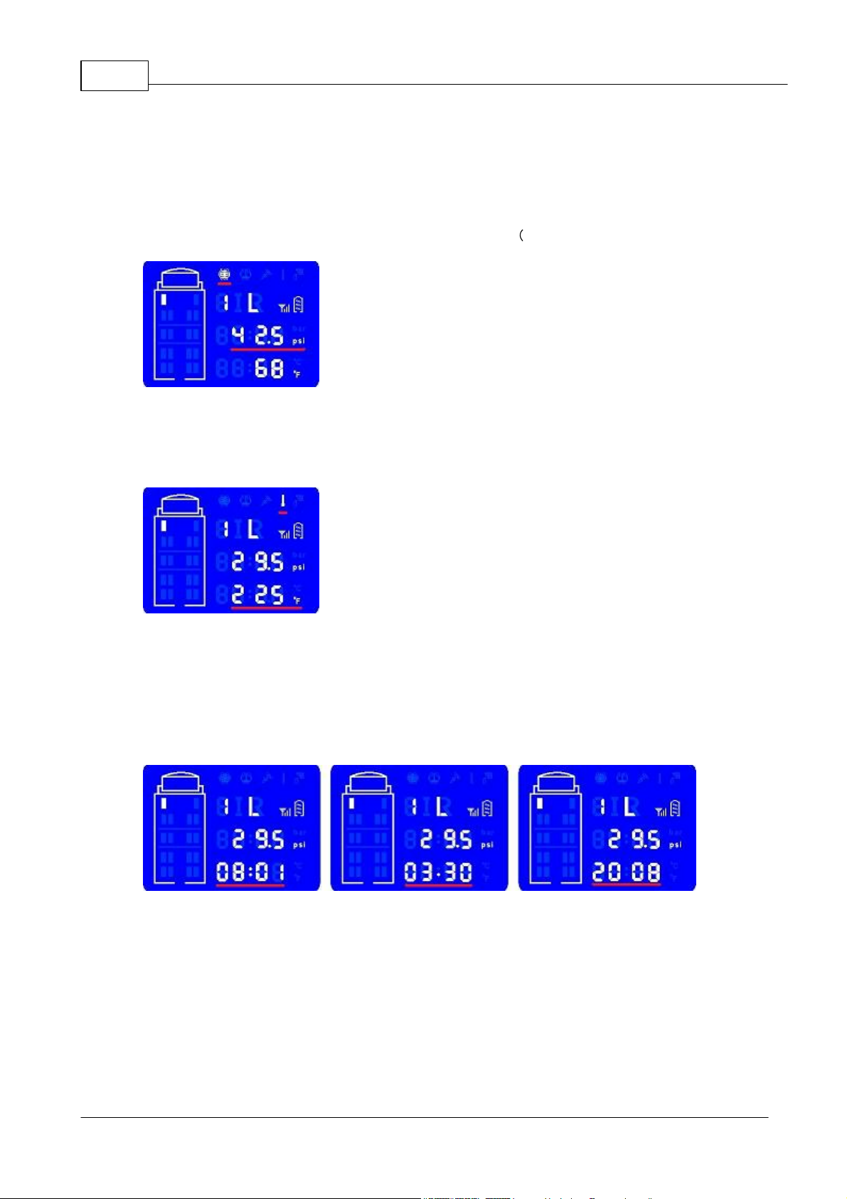
Time Display.
Press Down button to switch the display temperature units (°C to °F), press Down button again to
display time, date, year. (Figure 2.5.3)
© 2011 TRW Automotive, Parts & Service

LCD Display Monitor 8
fig.2.6.1
fig.2.6.2
2.6 First Low Pressure Alert and Second Low Pressure Alert (Panel ICON 3)
Function and Operation
First Low Pressure Alert
The system has a first low pressure alert at 15% below standard pressure value. The Alarm Indicator
flashes once every second. The Low Pressure Alert Indicator and the corresponding Tyre Position
will flash at the same time. (fig.2.6.1)
Second Low Pressure Alert
The system will have a second low pressure alert at 20% below standard pressure value. The Alarm
Indicator flashes twice every second. The Low Pressure Alert Indicator and the corresponding Tyre
Position will flash at the same time. (fig.2.6.2)
Warning: Do not respond to the alarm by applying vehicle brakes abruptly. The driver should
slow down and stop the vehicle ONLY when it is safe to do so. Check the tyre at your earliest
convenience.
© 2011 TRW Automotive, Parts & Service

EnTire Solution TPMS User Manual9
fig.2.7.1
fig.2.7.2
2.7 Sensor Malfunction Alarm and Sensor Low-Battery Power Alarm
Function and Operation
Sensor Malfunction Alarm
When a sensor malfunctions or monitor fails to receive tyre signal for over 20 minutes, the
corresponding Tyre Position will flash. Pressure Display Field will display “E-02”. fig.2.7.1)
Sensor Low-Battery Power Alarm (Panel ICON 8)
The LCD Display Monitor indicates sensor’s battery level. When it is low, Sensor Battery Indicator
will flash. (fig.2.7.2)
© 2011 TRW Automotive, Parts & Service

2.8 Rapid Leakage Alarm Indicator (Panel ICON 4)
fig.2.8.1
fig.2.9.1
Function and Operation
Rapid Leakage Alarm Indicator The system will alert and beep when tyre pressure drops 0.8psi
0.055bar within 8 seconds. The Alarm and the Rapid Leakage Alarm Indicator flash once every
second, the corresponding Tyre Position will flash at the same time. fig.2.8.1)
Warning: Do not respond to the alarm by applying vehicle brakes abruptly. The driver should
slow down and stop the vehicle ONLY when it is safe to do so. Check the tyre at your earliest
convenience.
LCD Display Monitor 10
2.9 Monitor Working Mode
Function and Operation
Monitor Working Mode: When the monitor is powered on, Alarm Indicator will flash once and the
system enters into working mode. It is ready to receive signal from sensors.
For a particular tyre sensor, if no signal is received, the Pressure Display Field will display “E-
01”and Temperature Display Field will display “----” . (fig.2.9.1).
Note: After initial power up of the monitor, it may take up to 15 minutes for a sensor to establish
communication with the monitor.
Briefly pressing “Prog” button will turn on or off LCD screen back light. (Panel item 17)
© 2011 TRW Automotive, Parts & Service

EnTire Solution TPMS User Manual11
4 + 0 EPK100
4 + 2 EPK103
2.10 Monitor Tyre Configuration
Note; To be used when configuring Display Monitor with additional sensors for trailer use.
Part numbers, EPK100. EPK101, EPK102 & EPK103 are factory pre-set to accept 4,6 or 8 sensors.
If you do not wish to configure the Display Monitor for additional axles at this stage, go to Section 2.11.
Year Setting and Date Setting
Parameter Setting Mode
Tyre Sensor Mapping Diagram.
The EnTire Solution TPMS can be configured to manage 4, 6, 8, 10, 12 and 14 tyre's in 12 different
configurations. To configure your LCD Display Monitor:
1.
Begin with LCD Display Monitor powered OFF.
2.
Press both the "Set" and "Prog" buttons simultaneously, switch the power ON switch.
3.
The LCD Display Monitor is now in tyre configuration mode.
4.
Press the "Up" button to scroll through the available tyre configuration.
5.
The LCD Display Monitor can support 4, 6, 8, 10, 12 and 14 tyre's in 12 different configuration.
6.
Press the "Down" button to save exit.
© 2011 TRW Automotive, Parts & Service

LCD Display Monitor 12
4 + 4
4 + 6
6 + 0 EPK101
6 + 2
6 + 4
6 + 6 EPK101 +EPK500
© 2011 TRW Automotive, Parts & Service

EnTire Solution TPMS User Manual13
8 + 0 EPK102
8 + 2
8 + 4
8 + 6 EPK102 + EPK500
© 2011 TRW Automotive, Parts & Service

2.11 Year Setting and Date Setting
fig.2.11.1
fig.2.11.2
Parameter Setting Mode
Operation of Buttons
Press and hold the “Set” button for 3 seconds, the system enters into setting mode. Press “Prog” button
to move cursor around and “Up” or “Down” button to increase or decrease the display value.
Year Setting
The LCD Display Monitor indicates “Se—y”. Set year based on above-mentioned operation. Press the
“Set” button to move to the next data input step. (fig.2.11.1)
LCD Display Monitor 14
Date Setting
The LCD Display Monitor indicates “Se—d”. Set the date accordingly (date format is MM.DD). Press the
“Set” button to move to the next data input step. (fig.2.11.2)
© 2011 TRW Automotive, Parts & Service

EnTire Solution TPMS User Manual15
fig.2.12.1
fig.2.12.2
fig.2.13.1
2.12 Time Setting and Standard Pressure Setting
Parameter Setting Mode
Time Setting
The LCD Display Monitor indicates “Se—C” and the time is displayed. Change it to your local time
accordingly. Press “Set” button to move to the next data input step. (fig.2.11.1)
Standard Pressure Setting
The LCD Display Monitor indicates (Se— P). Standard pressure is the cold tyre inflation pressure
recommended by the vehicle or tyre manufacturer. Please refer to your vehicle’s operation manual for
this value.
Tyre standard pressure is set axle by axle. Factory preset standard pressure values (bar) will be shown.
(fig.2.11.2)
Input your tyre’s standard pressure value for the axle row using “Prog”, “Up” and “Down” buttons.
After setting is complete, press the "Set" button to confirm
2.13 Alarm Temperature Setting
Alarm Temperature Setting After standard pressure input , it enters into alarm temperature setting state. Pressure data field displays “Se—t”. The factory preset default value is 176 ºF ˜ 80 ºC. Use function buttons to change it if you want a different threshold value. Press “Set” button to exit the setting mode. (fig.2.13.1)
The LCD Display Monitor is now ready for use!
© 2011 TRW Automotive, Parts & Service

3 Sensor
fig.20
3.1 Sensor Name and Tyre Diagram
Sensor Name and Tyre Diagram
Ensure that the LCD Monitor is installed and powered on.
The sensors are to be installed on valve stems. For correct sensor and tyre location, please refer below.
(fig.20)
LCD Display Monitor 16
© 2011 TRW Automotive, Parts & Service

EnTire Solution TPMS User Manual17
fig.3.2.1
fig.3.2.2
fig.3.2.3
fig.3.2.4
3.2 Sensor Installation
Sensor Installation
Ensure that the LCD monitor is installed and powered on.
Step 1. Use the provided spanner wrench to turn the cap anti-clockwise to open the sensor. (fig.3.2.1)
Step 2. Release sensor’s bottom cover from the sensor by pushing down on sensor’s valve stem
connector. (fig.3.2.2)
Step 3. Slip sensor’s bottom cover through the valve stem. (fig.3.2.3)
Step 4. Bring the inner sensor to the valve stem and turn clockwise until it is firmly tightened. A brief
hissing air sound should briefly occur when the sensor is being mounted. (fig.3,2,4)
© 2011 TRW Automotive, Parts & Service

Sensor 18
fig.3.2.5
fig.3.2.6
fig.3.2.7
fig.3.2.8
Step 5. Pull sensor bottom cover out (fig.3.2.5), match it with the upper cover cap and tighten it with the
spanner wrench. (fig.3.2.6)
Step 6. Sensor Anti-theft Function Test
Use fingers to spin the sensor body anti-clockwise to check if the sensor is spinning freely and can not
be removed by turning. (fig.3.2.7)
Step 7. Repeat steps 1-6 for other sensors.(fig.3.2.8)
Step 8. Verify if the sensor works properly.
The LCD Display Monitor should indicate the tyre status within 1 minute after installation.
Note: If there is no tyre information displayed after 15 minutes, please check the sensor’s battery
status, replace and reinstall the battery. Refer to “Troubleshooting” section on how to change a sensor’s
battery.
Note: If this is a replacement sensor please write with waterproof marker the correct sensor name on the
blank sensor label (i.e. 1R, 3L) according to tyre diagram (fig. 20)
© 2011 TRW Automotive, Parts & Service

EnTire Solution TPMS User Manual19
LCD Display Monitor
Working Temp. Range
-4°F +158°F / -20 +70
Working Frequency
433.92MHz±150KHz
LCD Display Monitor Size
3.9 x 2.8 x 0.8 LxHxW in inch) 10 x 7 x 2.1 LxHxW in cm)
LCD Size
2.3 x 2.4 x 1.9 LxHxW in inch) 5.9 x 6 x 4.7 (LxHxW cm)
Suction Holder Size
Ф 2.8 x 5.6 ( DxW in inch) Ф 70 x 142 ( DxW in mm)
Vehicle-charging Power Supply
Specifications
Input DC12V/24V,Output5V, 1.5A
Operating Power Supply
3.7V Rechargeable Lithium Battery503759 1100mAH
Operating Current
Normal 10 mA, Maximum alarm state 40 mA
Charge Current
Less than 600mA
Charge Time
Less than 3.5hrs
Battery Standby Time
More than96hrs (Charge when power meter is lower than 2nd grid)
Coding and Transmission Rate
Adopted Manchester Coding
Transmission rate9600bps
Receiver Sensitivity
-107dBm
Alarm Pressure
25% above; 15% and 20% below standard pressure
Display Mode
Digital and pictorial display
Interface
MIN USB-5Pin SMT Socket (ICDM-USB501F)
Sensor
Working Temperature Range
- 40°F +257°F / - 40 +125
Working Pressure Range
0-130 PSI/0-9 bar
Size
1.1 x 1.1 inch or 29.0 x 29.0 mm ( Φx H)
Weight
0.77 Oz or 22±1g (including battery)
Operating Voltage
DC3V (Manganese-Lithium battery CR1632)
Modulation
ASK
Battery Life Time
>1.5 Years normally, replaceable
Working Frequency
433. 92MHz ±100KHz
Transmitting Power
10dBm
Working Distance
~1000 inch / ~25 meters
Waterproof & Dust proof Rating
IP67
Installation Torque
0.7-1.0 N.M
4 Technical Specifications
© 2011 TRW Automotive, Parts & Service

Technical Specifications 20
fig.5.1.1
fig.5.1.2
5 Troubleshooting and System Maintenance
5.1 Tyre Inflation and Sensor Battery Replacement
Tyre Inflation
To add air to a tyre, disassemble the sensor first.
• Loosen the upper cover by turning it anti-clockwise with a spanner wrench. (fig.5.1.1)
• Turn the sensor body anti-clockwise to remove it from the valve stem.(fig.5.1.2)
• Inflate the tyre to the standard pressure. Measure it with a pressure gauge.
• Reinstall the sensor according to the installation steps. (Chapter 6.2 Sensor Installation)
Note - Once the sensor has been re-installed on the tyre valve, any previous warning will be reset.
© 2011 TRW Automotive, Parts & Service

EnTire Solution TPMS User Manual21
fig.5.1.3
fig.5.1.4
fig.5.1.5
fig.5.1.6
Sensor Battery Replacement
The typical battery life is >1.5 years. The battery is exchangeable. The monitor will alert if the sensor
battery is low. The relevant tyre position with a low battery power alarm will show on the LCD Display
Monitor (refer fig.2.3.1)
Note: LCD Display Monitor is not required to be switched on, this can be performed when LCD Display
Monitor is not switched on.
To replace a battery:
1. Loosen the upper cover of the sensor with a spanner wrench. Take out the inside sensor enclosure.
(fig.5.1.3)
2. Open the inside sensor cap by aligning spanner wrench to the 3 recess points at the bottom side of
the sensor and turn it anti-clockwise.
3. Push out the used battery as shown in picture. (fig.5.1.4)
4. Put a new CR1632 Manganese-Lithium battery in, with the positive side facing out. (fig.5.1.5)
5. Tighten the inside sensor body with a spanner wrench by turning it clockwise. (fig.5.1.6)
6. Reinstall the sensor.
Note: The monitor does not need to be switched on during sensor battery replacement.
© 2011 TRW Automotive, Parts & Service

5.2 Troubleshooting and Valve Stem Pin
Failure Code
Failure Analysis
E-01
Monitor has lost contact of a sensor for over 20 minutes. The possible
reason is the sensor is damaged or low on battery.
E-02
Sensor self-monitoring failure.
E-03
Sensor measurement (pressure or temperature ) range exceeded.
Good Condition
Pin Misalign
Corroded
Sensor Failure
Monitor Failure
If the monitor doesn’t turn on, check if the power cable is connected properly, and the vehicle's cigar
lighter socket power is on. Otherwise, the cable or the monitor itself might be damaged.
Note: Please contact your dealer for replacement sensor, monitor or cable.
Valve Stem Pin
Be sure to inspect and replace any defective, corroded or cracked valve stems before installing the
sensors. If replacements are necessary we suggest replacing the valve stems with a metal type stem.
This improves the life of the stem due to premature failure from drying out and cracking of inferior
manufactured stems.
The valve stem pin at each tyre position should now be checked to see if it is in the correct position to
allow the sensors to be activated by the air pressure from the tyres.
Troubleshooting and System
Maintenance
22
Valve Stem Pin Misalignment: If the valve stem pin is set too deep or off centred, the valve stem pin
will not make good contact with the sensor pin plunger, resulting in an incorrect or no resulting pressure
reading. Use a valve stem tool to adjust the pin out far enough to allow the pin tool to release air from the
valve stem. The pin should not be extracted to the point that air is released all the time from the valve
stem. This should be checked with the aid of a small amount of soapy water for air leaks.
© 2011 TRW Automotive, Parts & Service

EnTire Solution TPMS User Manual23
fig.5.4.1
fig.5.4.2
5.3 Sensor Working Modes
Sleep Mode Sensors are in sleep mode when they are received in original package. They enter into
working mode when mounted onto inflated tyres.
Normal Working Mode If there is no pressure change and the vehicle is not moving, the LCD Display
Monitor will be updated every 8 minutes. When vehicle moves it will update every 4 minutes.
If pressure drops 0.8 psi ˜ 0.055 bar within 8 seconds time period, a series of rapid leakage signal will
be transmitted to the monitor immediately. (refer fig.2.8.1 Rapid Leakage Alarm Indicator)
Learning Mode Take out the battery from the inner sensor for a minute and insert it back, the sensor
will transmit learning code 10 times. After that, it will go back to sleep mode.
Note: Perform Learning Mode operation ONLY when programming a new replacement or additional
sensors. E.g. For trailers
5.4 Programming of Replacement Sensor
Step 1. Remove replacement sensor’s outer cap and inner cover using a spanner wrench.
Step 2. Press “Prog” button for 8 seconds till you see the outline of the vehicles flashes. Push “Up” or
“Down” button to select the appropriate tyre position and “LRN” will flash. (fig.5.4.1) Push “Prog” button
to confirm. The sign “LRN”, and the outline of the vehicles will stop flashing.
Step 3. Take the battery out of the sensor for one minute (fig.5.1.4) and insert it back. A series of
learning code will be transmitted by the sensor. After the sensor is learned the monitor buzzer will beep
twice.
Pressure display field shows “End”.
Step 4. Press “Set” button to exit Learning mode. The monitor goes back to working mode. (fig.5.4.2)
Step 5. Put the inner sensor cover back. The senor is ready for installation onto the appropriate tyre
position (refer to: Sensor Installation).
© 2011 TRW Automotive, Parts & Service

6 After Sales Service
Warranty Terms
Products are covered by normal TRW warranty and Faulty ex-stock terms
The product warranty does not cover the following situations (Charge may apply):
1. Sensors and monitor are lost or damaged by user’s improper operation.
2. Original invoice can not be provided.
3. Unit is purchased from unauthorized dealers.
4. Sensor battery are not covered by warranty, replace if required with type CR1632 Manganese-Lithium
The technical support is provided through the product’s lifetime.
www.trwaftermarket.com
Troubleshooting and System
Maintenance
24
© 2011 TRW Automotive, Parts & Service

EnTire Solution TPMS User Manual25
Cold Pressure
(Standard)
The vehicle manufacturer recommended inflation pressure of a tyre
at ambient temperature (64 °F / 18 °C)
Alarm Pressure
The audible and visual alert activated when the tyre’s actual
pressure drops to the programmed value (Usually when the
pressure is 15% or more under-inflation).
LCD Display Monitor
The electronic module which can receive tyre pressure and
temperature info from sensor and have a visible and audible
warning.
Sensor
The electronic device which can detect tyre pressure, temperature
and transmit the data to monitor wirelessly.
kpa
Kg/cm²
bar
psi
kpa
1
0.0101972
0.01
0.145038
Kg/cm²
98.0665
1
.980665
14.2233
bar
100
1.01972
1
14.5038
psi
6.89476
0.0703072
0.0689476
1
7 Glossary
Glossary
Unit Conversion Table
© 2011 TRW Automotive, Parts & Service

Glossary 26
7000
7001 Cord
7008 3M
Tape
7009 Nylon Strip
7010 7011
1000
8 Appendix EPK 500 & Relay - To be used in conjunction
with section 2.10 Monitor Tyre Configuration
EPK500 & Relay Installation
EnTire Solution TPMS configured with more than eight sensors, must be installed with a Relay
(EPK500). This will boost the sensor signal range and make it effective and improve communication
reliability.
Parts diagram:
Relay
Cord - 7 Way Connector
Velcro and tie-wrap
Nylon Strip
Self-tapping screws (2)
Screw Nut&Shim) (2)
Sensor (6)
Display Monitor and Sensor Extension
Step 1: Re-configure the display monitor according to the installation steps. (Chapter 2.10 Monitor Tyre
Configuration)
Step 2: Re-configure the display monitor to learn each sensor (Chapter 5.4 Programming of
Replacement Sensor) in the appropriate tyre position (i.e. 7R, 8L) according to tyre diagram (fig. 20 in
Chapter 2.10 Monitor Tyre Configuration). Please write appropriate sensor name with water-proof marker
on blank inner sensor label and blank outer anti-theft sensor cap label.
Step 3: Check and set the standard tyre pressure setting (Chapter 2.12 Time Setting and Standard
Pressure Setting). Standard tyre pressure value, as recommended by tyre manufacturer, needs first to
be programmed into the system first before the system can work properly. Refer to your vehicle owner’s
manual for your tyres standard pressure value.
© 2011 TRW Automotive, Parts & Service
Step 4: Install new sensors on correct tyre valve stem (Chapter 3.1 Sensor Name and Tyre Diagram and
Chapter 3.2 Sensor Installation). Please note that the sensor’s weight (~0.63 Oz, 18.0±1 grams) may
affect the tyre‘s balance after installation. It is recommended that a user have the tyre balance checked
at a tyre installation centre.

EnTire Solution TPMS User Manual27
fig.8.1.1 - 7-Way Connector
fig.8.1.2 - 7-Way Connector
fig.8.1.3
fig.8.1.4
Relay Installation
Step 1: Select a suitable location to mount the relay onto the bottom of the vehicle undercarriage as
close as possible to the furthest rear tyre sensor from the LCD Display Monitor. Locate the vehicle's
external DC power port and 7 power connector. (fig.8.1.1 and fig.8.1.2) Select a position for the relay that
will have the clearest path and to where the LCD Display Monitor is mounted, make sure there is some
clear space around the relay antenna to prevent blocking its reception and transmission. Clean truck
undercarriage surface and mount relay with self-tapping screws, Velcro and tie-wrap to the selected area
of the truck undercarriage. Make sure the distance between the relay and the truck's 7 Way power
connector socket is within the reach of the enclosed relay 7 Way connector extension (1.2 meter).
(fig.8.1.3)
Step 2: Attach to the vehicle's external +12 V or +24 V DC power supply to the relay with provided 7Way power connector,
Brown line connected power supply positive,
Blue line connected power supply negative.
The relay's red LED will then light up. (fig.8.1.4)
Step 3: Confirm relay is working with all sensors, (See 5.3 Sensor Working Modes, if you install the
relay after you install the sensor the signal may take up to 8 minutes to register with the LCD Display
Monitor because there is no abnormal pressure condition and sensors are now in Normal Working
Mode). The LCD Display Receiver should cycle through all the tyre pressure, temperature and
transmission signal and sensor battery information. Note: Sensors are in normal working mode and it
may take 8 minutes for each sensor to start to cycle their signal.
© 2011 TRW Automotive, Parts & Service

Appendix EPK 500 & Relay - To be
7-Way Connector
Relay
Operating temperature range
- 40 °C to + 85 °C
Receiving Frequency
433.92MHz ± 150KHz
Receiver Sensitivity
-107dBm
Transmit Frequency
433. 92MHz ± 100KHz
Transmit Power
<10dBm
Voltage
DC12V/24V
Operating current
<15mA
Working distance
> 25 m
Size Length Width
4.3 x 2.4 x 1.3 LxHxW in inch) 10.9 x 6 x 3.4 LxHxW in cm)
used in conjunction with section 2.10
Monitor Tyre Configuration
Troubleshoot Sensor and Relay
If a tyre sensor can not be located:
1.
Troubleshoot the sensor and valve stem pin. (See 5.2 Troubleshooting Sensor and Valve Stem)
2.
To troubleshoot a particular wheel location, fix LCD Display Monitor to the wheel location (fig.2.4.1)
3.
Take the LCD Display Monitor in hand to the wheel location where the sensor is attached. Briefly
loosen the sensor to release some air (you should hear a hiss) and then re-mount sensor, the sensor
will transmit 4 signals to the monitor in 4 second intervals. You have 12 seconds to return to the LCD
Display Mount position before the sensor returns to normal working mode (i.e. normal 8 minutes
signal transmission cycle).
4.
If you determine that the sensor is working properly and you do not receive a signal from the relay, the
position of the relay maybe affecting the wireless reception. Please re-install and change the location
of the relay.
Relay Specifications
28
© 2011 TRW Automotive, Parts & Service
 Loading...