


DVR User Manual
TVR-40
4-channel digital video recorder
All rights reserved

HD-TVI DVR U s er Manual
CAUTION
Please read this user manual carefully to ensure that you can us e th e device correctly and
safely.
There may be several t echnically inco r rect places or printing errors in this manual. The
updates will be added into the new version of this manual. The contents of this manual are
subject to change without notice.
This device should be operated only from the type of power source indicated on the
marking label. The voltage of the power must be verified before using. If the device doesn’t
work for a long time, pull out the plug from the socket.
Do not install this device near any heat sources such as radiators , heat registers, stoves or
other device that produce heat.
Do not install this device near water. Clean only with a dry cloth.
Place the device in a well-ventilated area.
Do not power off the DVR at normal recording condition!
This machine is indoor using equipment. Do not expose the machine in rain or moist
environment. In case any solid or liquid get into the machine’s case, please cut off the power
supply immediately, and ask for qualified techni cians to check the machine before restart
Do not try to repair the device by yourself without technical aid or approval.
When this product is in use, the relevant contents of Microsoft, Apple and Google will
be involved in. The pictures and screenshots in this manual are only used to explain the
usage of our product. The ownerships of trademarks, logos and other intellectual properties
related to Microsoft, Apple and Google shall belong to the above-mentioned companies.
This manual is suitable for 4/8/16-channel HD-TVI digital video recorders. All examples
and pictures u s ed i n the manual are from 4-channel DVR.

HD-TVI DVR U s er Manual
Table of Contents
1 Introduction ....................................................................................................................... 1
1.1 DVR Introduction ................................................................................................................ 1
1.2 Main Features ...................................................................................................................... 1
2 Hardware Installation ....................................................................................................... 3
2.1 Install Hard Drive ................................................................................................................ 3
2.2 Front Pane l De s c r ipt io ns ...................................................................................................... 4
2.3 Rear Panel Instructions ........................................................................................................ 4
2.4 Remote Controller ............................................................................................................... 5
2.5 Control with Mouse ............................................................................................................. 6
2.5.1 Connect Mouse ................................................................................................................. 6
2.5.2 Use Mouse ........................................................................................................................ 6
3 Basic Func tion Instructi o n ................................................................................................ 8
3.1 Power On/O ff ...................................................................................................................... 8
3.1.1 Powe r On .......................................................................................................................... 8
3.1.2 Powe r Off ......................................................................................................................... 8
3.2 Login ................................................................................................................................... 8
3.3 Live Preview ........................................................................................................................ 9
3.4 Live Playback ...................................................................................................................... 9
4 Main Menu Setup Guide ................................................................................................. 10
4.1 Basic Configuration ........................................................................................................... 10
4.1.1 Sys tem ............................................................................................................................ 11
4.1.2 Time & Date ................................................................................................................... 11
4.1.3 DST ................................................................................................................................ 12
4.2 Live Configuration ............................................................................................................ 12
4.2.1 Live ................................................................................................................................. 12
4.2.2 Main Mon it or .................................................................................................................. 13
4.2.3 Mask ............................................................................................................................... 13
4.3 Record Configuration ........................................................................................................ 14
4.3.1 Enable ............................................................................................................................. 15
4.3.2 Record Bitrate ................................................................................................................. 15
4.3.3 Time ................................................................................................................................ 16
4.3.4 Stamp .............................................................................................................................. 16
4.3.5 Recycle Record ............................................................................................................... 17
4.3.6 Snap ................................................................................................................................ 17
4.4 Schedule Co nfiguration ..................................................................................................... 18
4.4.1 Schedu le ......................................................................................................................... 18
4.4.2 Motion Sche d ul e ............................................................................................................. 19
4.5 Alarm Configuration .......................................................................................................... 19
4.5.1 Motion Ala rm ................................................................................................................. 19
4.5.2 Video Loss ...................................................................................................................... 21
4.5.3 Other Alarm .................................................................................................................... 21

HD-TVI DVR U s er Manual
4.5.4 Ala rm Out ....................................................................................................................... 22
4.6 Network Configuration ...................................................................................................... 22
4.6.1 Network .......................................................................................................................... 22
4.6.2 Sub St ream ...................................................................................................................... 23
4.6.3 Email .............................................................................................................................. 24
4.6.4 Server.............................................................................................................................. 24
4.6.5 NAT ................................................................................................................................ 25
4.6.6 Other Settings ................................................................................................................. 25
4.7 User Management Configuration ....................................................................................... 28
4.8 P.T.Z Conf i g ur a t ion ........................................................................................................... 29
4.9 Advanced ........................................................................................................................... 33
4.9.1 Reset ............................................................................................................................... 33
4.9.2 Import/Export ................................................................................................................. 33
4.9.3 Block/Allow List ............................................................................................................ 33
5 Search, Playb ack & Backup ........................................................................................... 34
5.1 Time Search ....................................................................................................................... 34
5.2 Event Search ...................................................................................................................... 35
5.3 File Management ............................................................................................................... 35
5.4 Search by Image ................................................................................................................ 36
5.5 Backup ............................................................................................................................... 36
6 Manage DVR ................................................................................................................... 38
6.1 Check System Information ................................................................................................ 38
6.1.1 Sys tem Information ........................................................................................................ 38
6.1.2 Event Information ........................................................................................................... 38
6.1.3 Log Information .............................................................................................................. 38
6.1.4 Network Information ...................................................................................................... 38
6.1.5 Online Information ......................................................................................................... 38
6.1.6 Record Information ......................................................................................................... 38
6.1.7 QRCODE ........................................................................................................................ 38
6.2 Disk Management .............................................................................................................. 39
6.3 Upgrade ............................................................................................................................. 40
6.4 Logoff ................................................................................................................................ 40
7 Remote Surveilla nce ........................................................................................................ 41
7.1 IE Remote Sur vei llance by NAT ....................................................................................... 41
7.1.1 NAT Settings................................................................................................................... 41
7.1.2 NA T A ccess .................................................................................................................... 41
7.2 IE Remote Sur vei llance via LAN & WAN ........................................................................ 42
7.2.1 Via LAN ......................................................................................................................... 42
7.2.2 Via WAN ......................................................................................................................... 42
7.3 Remote Surveillance through Apple PC ............................................................................ 43
7.3.1 Via LAN ......................................................................................................................... 43
7.3.2 Via WAN ......................................................................................................................... 44
7.4 The Remote Live P r evi ew ................................................................................................. 45
7.5 Remote Playback & B ackup .............................................................................................. 47

HD-TVI DVR U s er Manual
7.5.1 Remote Playback ............................................................................................................ 47
7.5.2 Remote Backup............................................................................................................... 50
7.6 Remote System Configuration ........................................................................................... 50
7.7 Tools .................................................................................................................................. 51
7.8 Remote Management ......................................................................................................... 51
Appendix A F AQ ................................................................................................................. 52
Appendix B Calculate Recording Capacity ...................................................................... 56
Appendix C Compatible Devices ....................................................................................... 57
Appendix D 4 CH Specificati ons ....................................................................................... 58
Appendix E 8 CH Specificati ons ........................................................................................ 59
Appendix F 16 CH Specificat ions ...................................................................................... 60

HD-TVI DVR U s er Manual
1
1 Introduction
1.1 DVR Introduction
This model is standard 4/8/16 CH 1080P/720P/960H high resolution DVRs, which adopts
high performance video processing chips and embedded Linux system. Meanwhile, it utilizes
many most advanced technologies, such as standard H.264 with low bit rate, Dual stream,
SATA interface, VGA output mouse supported, IE browser supported with full remote control,
mobile view(by phones), etc., which ensure its powerful functions and high stability. Due to
these distinctive characteristics, it is widely used in banks, telecommunication, transportation,
factories, warehouse, and irrigation and so on.
1.2 Main Features
COMPRESSION FORMAT
• Standard H.264 compression with low bit rate and better image quality
LIVE SURVEILLANCE
• Supports HDMI/ VGA output
• Supports 4/8/16 CH (HD-TVI signal)1080P@25/30FPS, 720P@25/30/50/60FPS,
(analog signal)960H, D1video input
• Supports channel security by hiding live display
• Display the local record state and basi c information
• Supports USB to make full control
RECORD MEDIA
• Supports one SATA HDD to record for a longer time without any limitation
BACKUP
• Supports USB 2.0 devices to backup
• Supports saving recorded files with AV I standard format to a remote computer through
internet
RECORD & PLAYBACK
• Record modes: Manual, Schedule and Motion detection recording
• Supports recycle after HDD full
• Resolution, frame rate and picture quality are adjustable
• 1 audio channels available
• Three record search modes: time search, event search and image search
• 4/8 channels playback simultaneously
• Supports deleting and locking the recorded files one by one
• Supports remote playback in Network Client through LAN or internet
ALARM
• Supports schedule for motion detection

HD-TVI DVR U s er Manual
2
• Supports pre-recording and post recording
PTZ CONTROL
• Supports v a ri ous PTZ pr ot ocols
• Supports 128 PT Z pr e s e ts and 8 auto cruise tracks
• Supports remote PTZ control through internet
SECURITY
• Customize user right: log search, system setup, two way audio, file management, disk
management, remote l ogin, live view, manu al record, playback, PTZ con trol and remote live
view
• Supports 1 administrator and 63 users.
• Supports event log recording and checking, events unlimited
NETWORK
• Supports T CP/IP, DHCP , PPPoE, DDNS protocol
• Supports NAT technology
• Supports IE browser to do remote view
• Supports QRCODE Scanning through mobile phone client
• Supports setup client connection amount
• Supports dual stream. Network stream is adjustable independently to fit the network
bandwidth and environment.
• Supports picture snap in remote live
• Supports remote time and event search, and channel playback with picture snap
• Supports remote PTZ control with preset and auto cruise
• Supports remote full menu setup, changin g al l the DVR parameters remotely
• Supports mobile surveillance b y phones with iPhone, Android & Blackberry OS
• Supports CMS/NVMS to manage multi devices on i nt er net
HD-TVI DVR U s er Manual
3
2 Hardware Installation
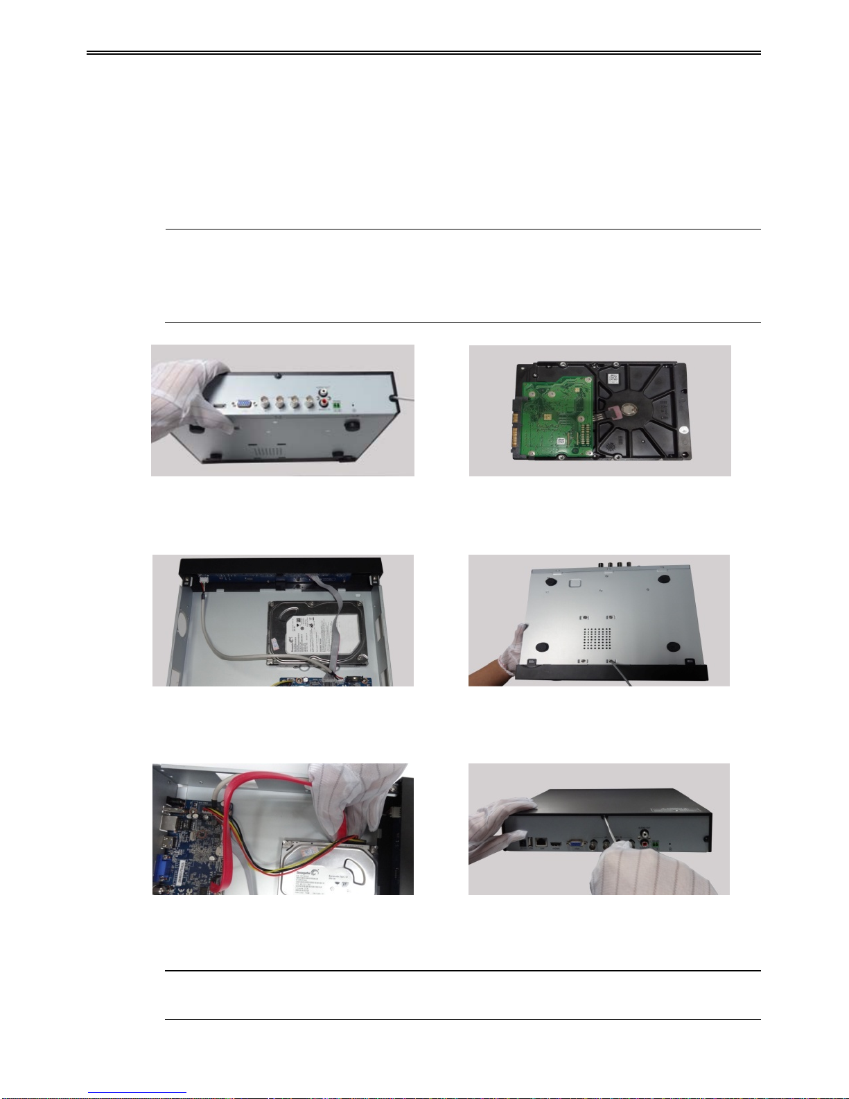
2.1 Install Hard Drive
Check the unit and th e accessories after getting the DVR. Please don’t power up the unit till
the physical installation is complete.
Notice: 1. This series support one SATA hard drive. Please use the hard drive the
manufacturers recommend specially for security and safe field.
2. Please calculate HDD capacity according to the recording setting. Please refer to
“Appendix B Calculate Recording Capacity”.
① Loosen the screws on the back and side ② Take out the HDD.
of the device to remove the cover.
③ Put the HDD on the bottom of the ④
Turn over the device and fix the HDD
device. with the screws.
⑤ Connect the power and data cables. ⑥ Install the cover back and fix it with the
screws.
Note: For convenience installation, please connect the power and data cables first and
then fix the HDD with the screws.
HD-TVI DVR U s er Manual
4
2.2 Front Panel Descriptions
Notice: The front panel descriptions are only for reference; please make the ob ject as
the standard.
Front pa ne l I
Name Description
REC
When reco rding, the light is bl ue
Net
When access to network , the light is blue
Power
Power indicator, when connection , the light is blue
Fn
Switch the resolution of the VGA / HDMI output
Front pa ne l II
Name
Description
Power indicator
Power Indicator, when connected, the light is blue.
HDD indicator
The ligh t tu r n s blue when reading/writing HDD.
Net indicator
The light turns blue when it is able to access the network.
Backup indicator
The ligh t tu r n s blue when backing up files and data.
Play indicator
The light turns blue when playing video.
REC indicator
The light turns blue when recording
Record button
Record manually
Play button
Enter pla y interface
REW button
Rewind key
FF button
Fast forward
MENU/+ button
1. Enter menu in live 2. Increase the value in setup
BACKUP/- button
1. Decrease the value in setup 2. Enter backup mode in live
STOP/ESC button
1. Quit play mode 2. Exit the current interface or status
Direction button/
Multi-screen
Change direction to select items
Change screen display mode like1/4/9/16 channel
Enter button
Confirm selection
USB
Connect to USB mouse, or USB storage device
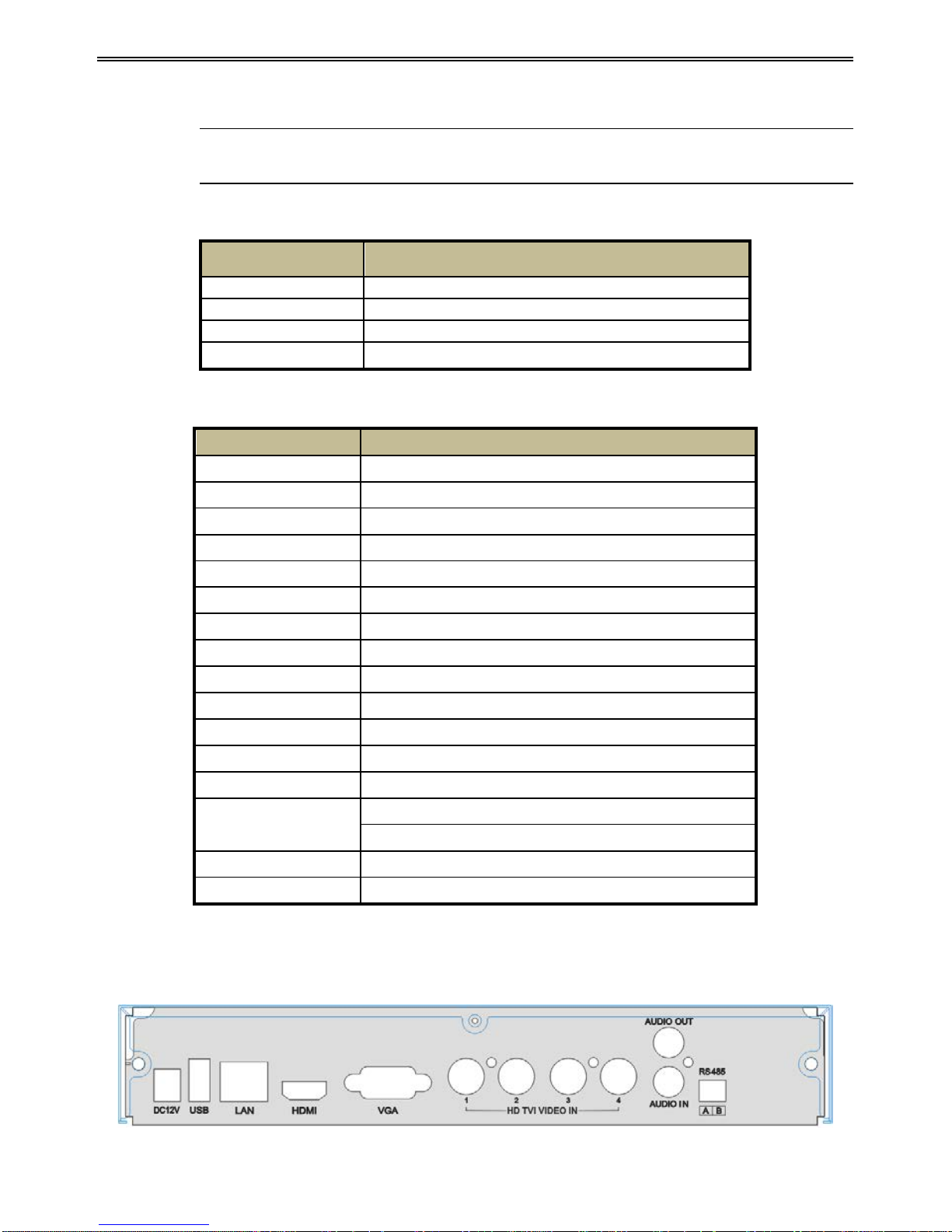
2.3 Rear Panel Instructions
Rear Panel for 4 CH
HD-TVI DVR U s er Manual
5
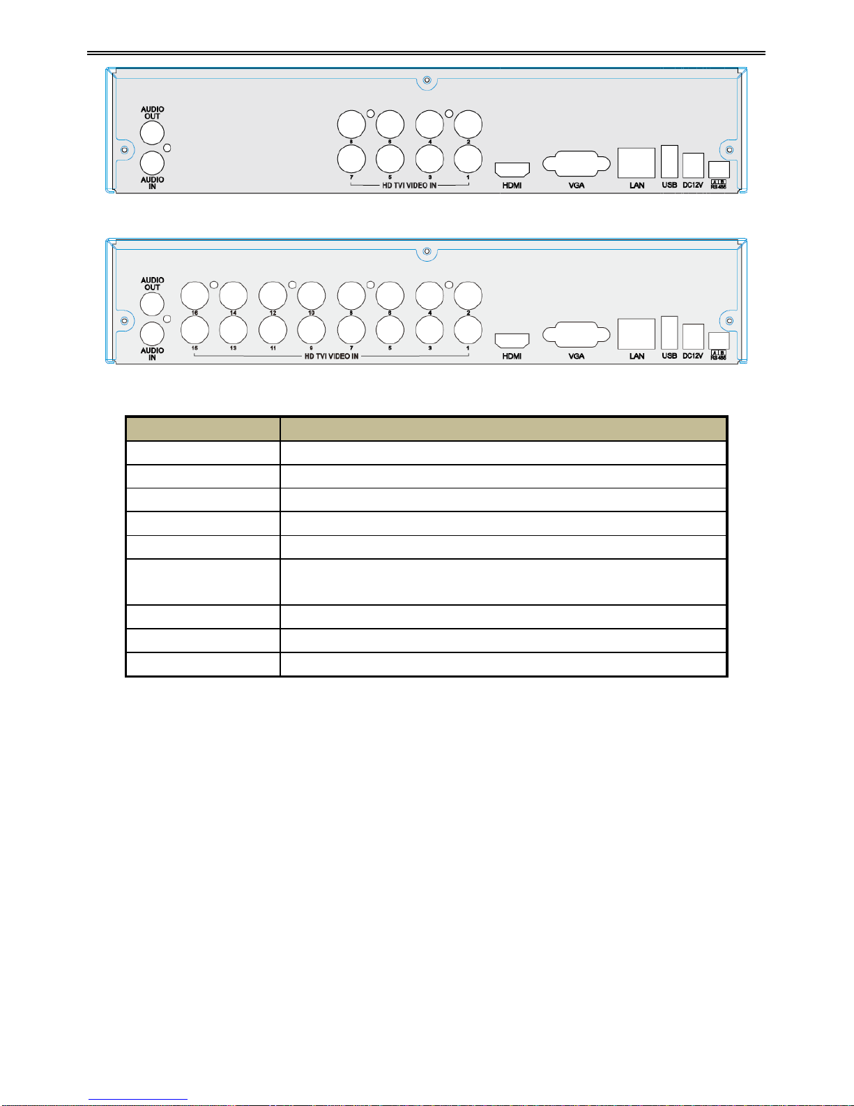
Rear Panel for 8 CH
Rear Panel for 16 CH
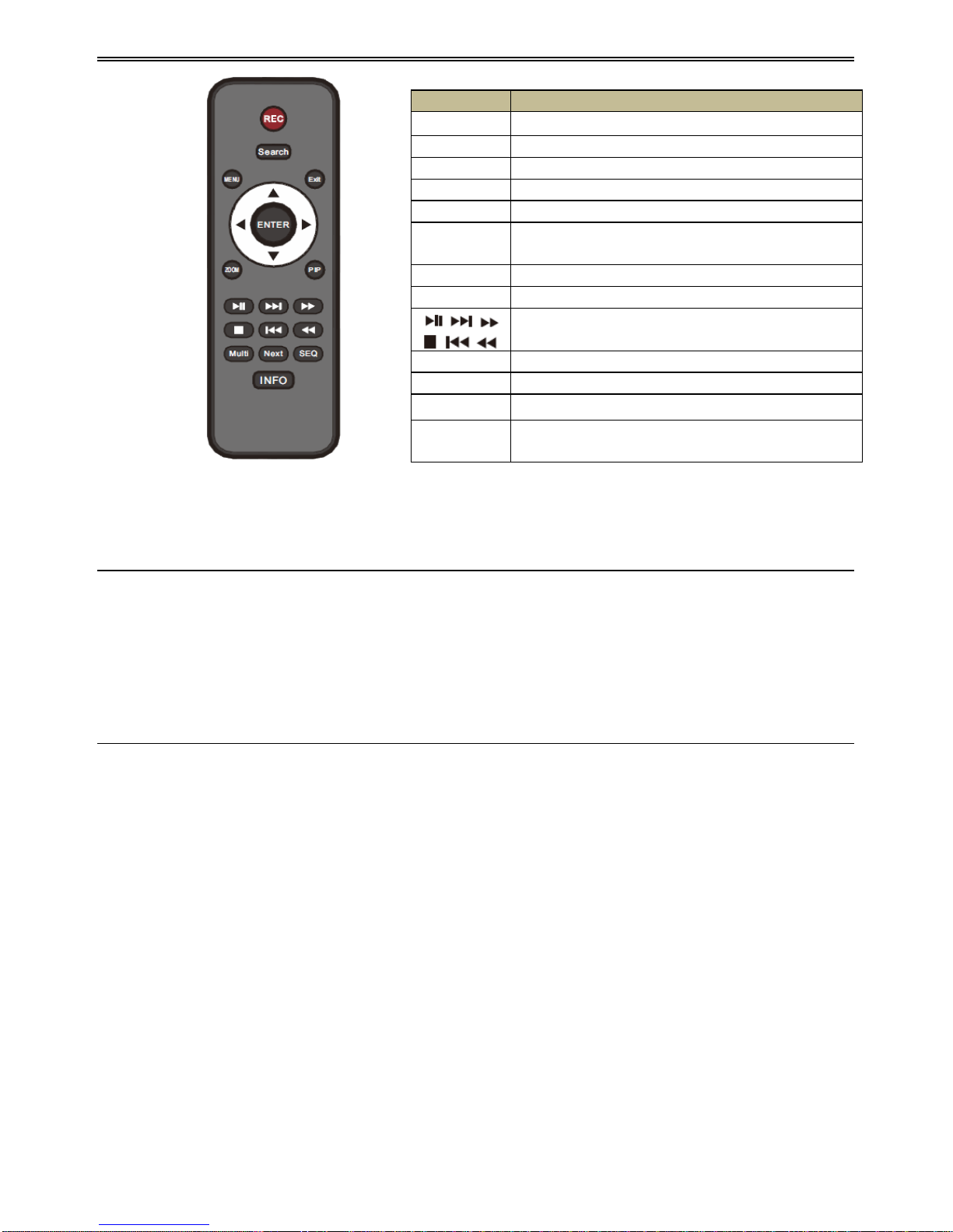
2.4 Remote Controller
It uses two AAA size batteries.
① Open the batter y cover of the remote controller.
② Place batteries. Please take care the polarity (+ and -).
③ Replace the battery cover.
Key points to check in case the remote doesn’t work.
1. Check batter ies polarity.
2. Check the remaining charge in the batteri es .
3. Check IR contr oller sensor for any masking.
If it still doesn't wor k, please change a new remote controller to try, or cont act your dealers.
The interface of remote controller is shown below.
Name
Descriptions
DC12V
DC12V Power Input.
USB
To connect external USB devices like USB mouse or USB storage device.
LAN
Network Port.
HDMI
HDMI Port. Connect to high-definition display device.
VGA
VGA Port. Connect t o monitor.
HD TVI VIDEO IN
Support (HD-TVI si gna l) 1080 P@25/30fps , 72 0P@25/30/50 /60fp s, ( analog
signal) 960H, D1 video input.
AUDIO OUT
Audio output, connect to the sound box.
AUDIO IN
1 CH Audio Input.
RS485
Connect to keyboard or speed dome; A is TX +; B is TX-.
HD-TVI DVR U s er Manual
6
2.5 Control with Mouse
2.5.1 Connect Mouse
It supports USB mouse through the ports on the rear panel.
If mouse is not detected or doesn't work, check below steps:
1. Make sure the mouse is plugged in the USB mouse port.
2. Try with a good know mouse.
2.5.2 Use Mouse
During live:
Double-click on any camera window to see the full screen. Double-click again to return to the
previous screen .
Right click to reveal the control menu on the screen. Right click again to hide the menu.
In Configuration:
Click to enter a particular option. Right click to cancel the option or to return to the previous
menu.
In order to input a value in a particular screen, move cursor to the input box and click. An
input window will appear as below. It supports digits, alphabets and symbols input. Click Shift
button to input Capital letters and symbols; click Shift button again to return.
It supports mou se drag. Take setting up motion detection ar ea for example: Click cu stomized,
hold down the left button and drag to set motion detection area.
Button
Function
REC
Record manually.
Search
To enter search mode.
MEUN
To enter menu.
Exit
To exit the curr ent i nterf ace .
ENTER
To confirm the choice or setup.
Direction
button
To move cursor in setup.
ZOOM
To zoom in.
PIP
To set picture in picture.
To control playback. Play/Pause/Stop/Previous
Section/Next Section/Rewind/Fast Forward.
Multi
To choose multi screen display mode.
Next
To switch between single picture and pict ure group.
SEQ
To enter auto dwell mode.
INFO
Get information about DVR like firmware version,
HDD information.

HD-TVI DVR U s er Manual
7
Click to choose the options. Right click to return to live mode.
In Backup:
Click to choose the options. Right click to return to previous picture.
In PTZ Co ntrol:
Click left button to choose the buttons to control the PTZ. Click right button to return to live.
Note: Mouse is the default tool for all operations unless an exception, as indicated.
HD-TVI DVR U s er Manual
8
3 Basic Function Instruction
3.1 Power On/Off
Before you power on the unit, please make sure all the connection is good.
3.1.1 Power On
① Connect with the power.
② The device will boot and the power LED would turn blue.
③ A WIZZARD wi n d ow will po p up and show some information about time zone, time
setup, network configuration, record configuration and disk management. User can set
up here and refer to the concrete setup steps from the corresponding chapters. If users
don’t want to set up Wizard, please click Exit button to exit. Press and hold FN/ESC key
to switch the resolution of the VGA/HDMI output.
3.1.2 Power Off
You can power off the device by using remote controller, keyboard and mouse.
① Go to
Menu and then select “Shut Down” icon to pop up the Shut down window.
② Click OK. Then the unit will power off after a while.
③ Disconnect the power.
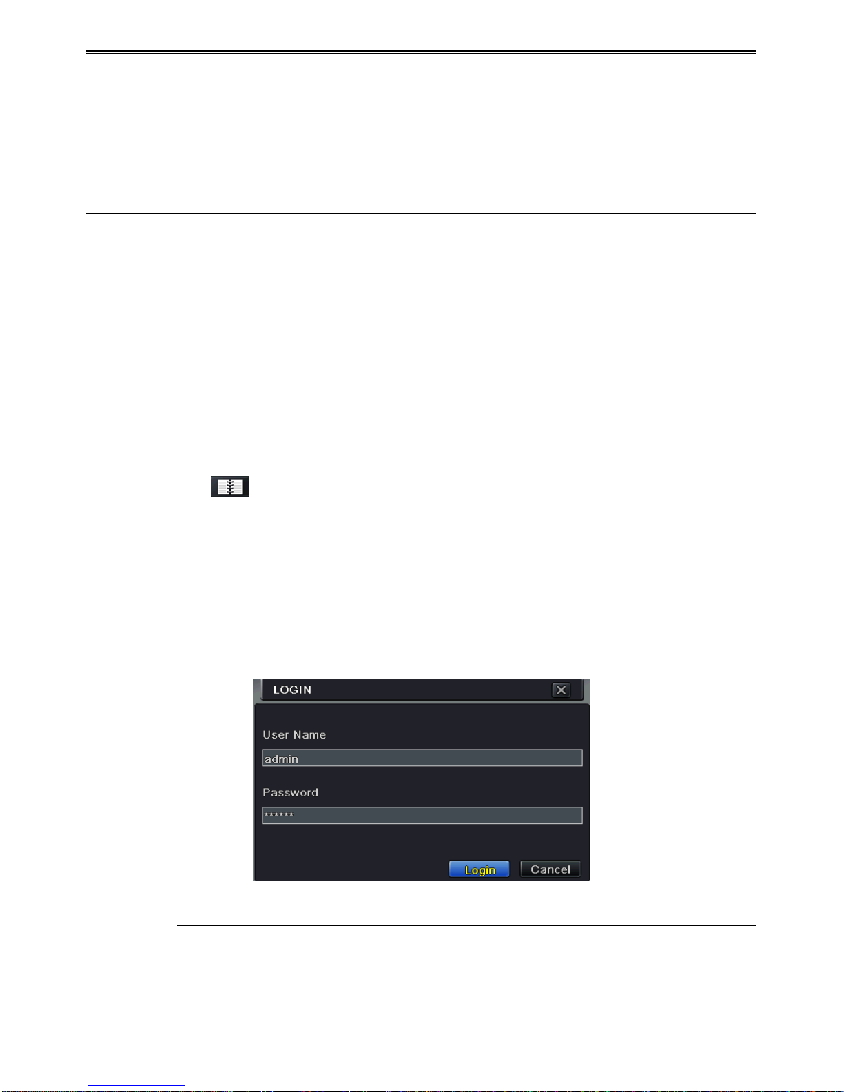
3.2 Login
User can login or log off the DVR system. Once logged off the user cannot do any other
operation except changing the multi-screen display.
Fig 3-1 Login
Notice: The default user name is “admin” and the default password is “123456”.
For complete operational steps for changing password, adding or deleting users,
please refer to section 4.7 User Management Configuration.

HD-TVI DVR U s er Manual
9
3.3 Live Preview
Fig 3-2 Live Previe w Interface
3.4 Live Playback
Click Playback button to playback the record. Refer to Fig 3-3. User can do complete
operation b y clicking the buttons on screen.
Fig 3-3 Live Playback
Symbol
Meaning
Green
Manual record
Yellow
Motion detection reco rd
Blue
Schedule record
HD-TVI DVR U s er Manual
10
4 Main Menu Setup Guide
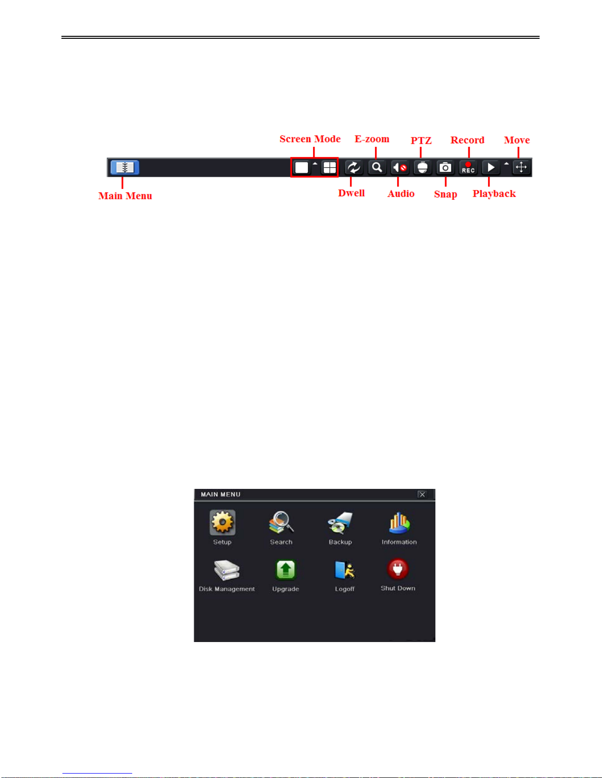
Click right mouse or press FN/ESC button on the front panel and then the control bar will
display at the bottom of the screen. Refer to Fig 4-1.
Fig 4-1 Main Menu Toolbar
Screen Mode: Click to choose screen mode.
Dwell: Dwell means to display li ve images fro m different cameras in a sequ ence. The images
may be displayed as a singl e chan nel o r in a grid fash ion fro m differen t cameras. Dwell mode
is enabled only when the chosen display mode is not able to display all the available cameras.
E-Zoom: Single channel l arge screen electronic amplification.
Audio: Enable sound.
PTZ: Click the PTZ button to control rotation position, speed and auto scan of the PTZ.
Snap: Click this button to snap th e live p ict ures . These p ict ur es will aut omatical l y be saved in
the SATA disk.
Record: Click this button to start/stop recording.
Playback: Click this button to playback the record fil es .
Click Main Menu butt on to pop up a windo w as Fig 4-2. You can also press MENU but ton on
the front panel or operate with remote controller to display the main menu. Clicking Setup
icon will pop up the configuration menu.
Fig 4-2 Setup
4.1 Basic Configuration
Basic configuration includes three sub menus: system, date & time and DST.
HD-TVI DVR U s er Manual
11
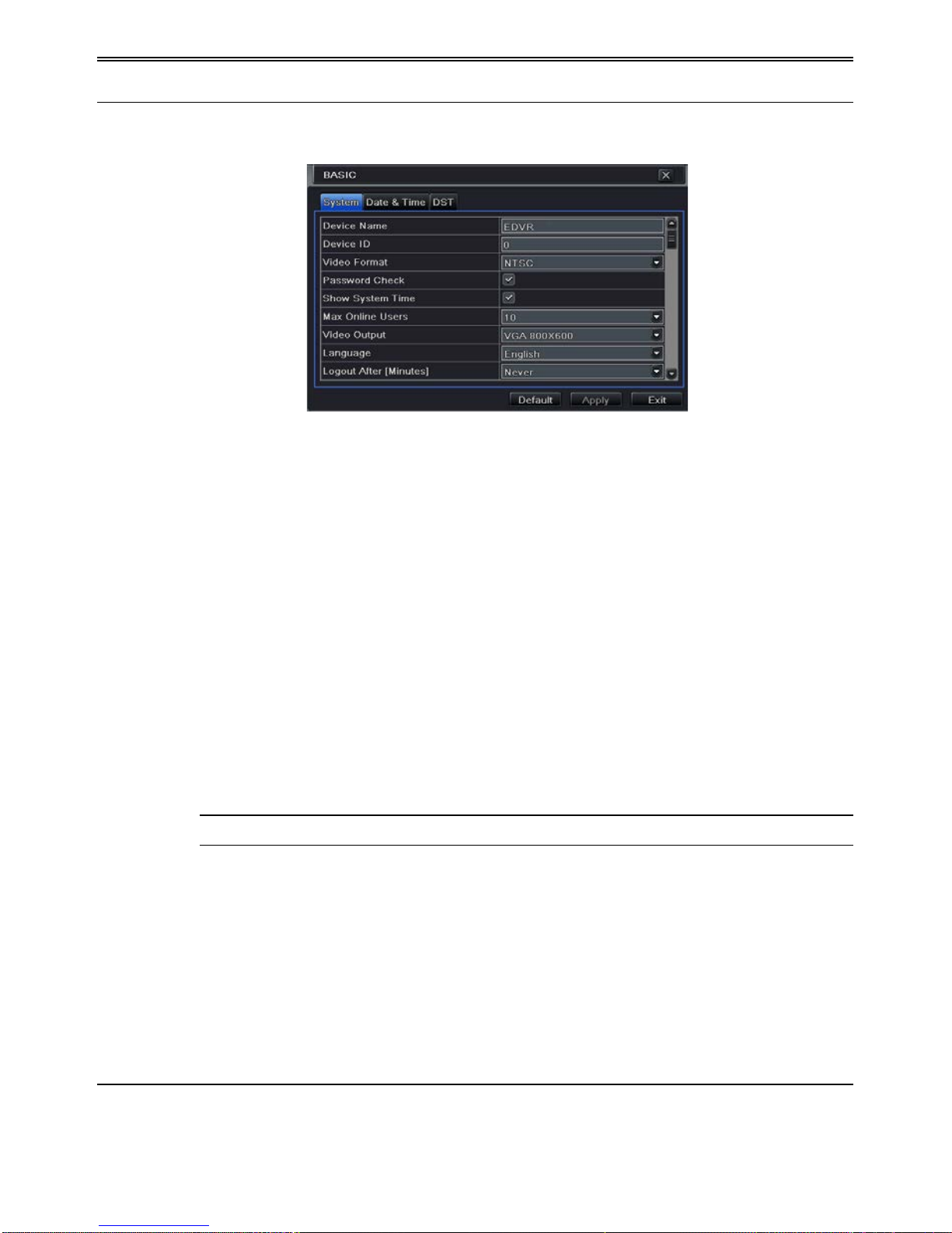
4.1.1 System
Go to MenuSetupBasic System interface. Refer to Fig 4-3.
Fig 4-3 Basic Configuration-System
In this interface you can set up the device name, devi ce ID, video format, max network users,
VGA resolution, language and so on. The definitions for every parameters display as below:
Device Name: The name of the device. It may display on the client end or CMS that help user
to recognize the device remotely.
Device ID: This ID is used to map the speed dome cameras.
Video Format: Two modes: PAL and NTSC. User can select the video format according to
that of camera.
Password Check: If this option is enabled, the user would need to input the user name and the
password for performing corresponding operations.
Show System Time: If selected, the current time will be displayed during live monitoring.
Max Online Users: To set the max number of concurrent user logins in the DVR.
Video Output: The resolution of live display interface.
Language: Set up the menu language.
Note: After changing the language and video output, the device needs to login again.
Logout After (Minutes): A user can set up the screen interval time (30s, 60s, 180s, 300s). If
there is no any operation within the setting period, the device will auto logout and return to
login interface.
Show Wizard: If selected, the GUI would launch the startup wizard on every boot, allowing
the user to do basic setup.
No Image When Logout : If selected, there will be no image showing when logging out.
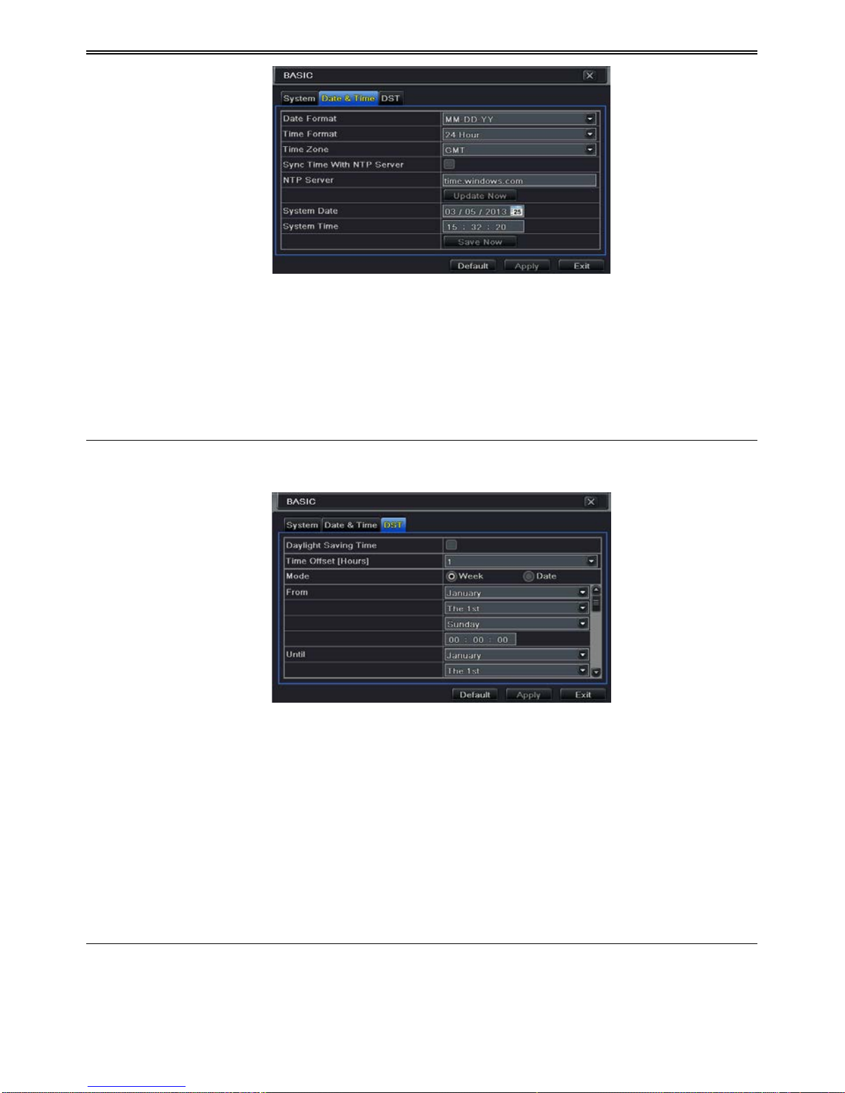
4.1.2 Time & Date
① Go to MenuSetupBasic Date & Time interface. Refer to F ig 4-4.
HD-TVI DVR U s er Manual
12
Fig 4-4 Basic Configuration-Date & Time
② Set the date format, time format, time zone in this interface; checkmark “Sync Time
With NTP Server” to refresh NTP server date. You can also adjust system date manually.
③ Click “Apply” button to save the setting.
4.1.3 DST
① Go to MenuSetupBasic DST interface. Refer to Fig 4-5.
Fig 4-5 Basic Configuration-DST
② In this interface, enable daylight saving time, time offset, mode, start & end
month/week/date, etc.
③ Click “Apply” button to save the setting.
4.2 Live Configuration
Live configuration includes three submenus: live, main monitor and mask.
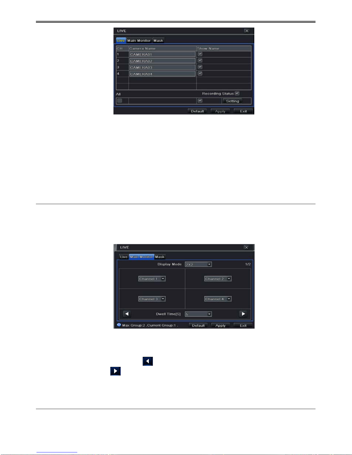
4.2.1 Live
In this interface, you can set up camera name.
To set up camera na me:
① Go to MenuSetupLive. Refer to Fig 4-6.
HD-TVI DVR U s er Manual
13
Fig 4-6 Live ConfigurationLive
② A software keyboard will pop up by clicking camera name area. Click the letters and (or)
digital numbers on the keyboard to input the name you want to display in live image.
③ Checkmark the ca mera name in the show name area.
④ All channels will show the camera name by chec king “All” checkbox.
⑤ Click “Apply” to save the setting.
4.2.2 Main Monitor
The main monitor s ettings allow you to set camera sequence in live display mode.
Operate the following steps to set main monitor:
① Go to MenuSetupLive Main Monitor interface. Refer to Fig 4-7.
Fig 4-7 Live C onfiguration-Main Monitor
② Select display mode and channel.
③ Select dwell time. Click button to set up the previous channel groups of dwell
picture. Click
button to set the latter channel groups of dwell picture.
④ Click “Apply” to save the setting.
4.2.3 Mask
If there is something you don’t want to display in the live image. You can set mask. For a

HD-TVI DVR U s er Manual
14
given channel a maximum of three areas can be masked.
To set up mas k area:
① Go to MenuSetupLive Ma sk interface.
Fig 4-8 Live Configuration-Mask
② Click Setting button to go into live image.
③ Press and drag the left mouse button to set mask area as shown below.
④ Right click to exit the mask setting interface.
⑤ Click Apply button to save the setting.
To del ete mas k area
① Click Setting button in the mask interface.
② Select a certain masked area and double click to delete that masked area.
③ Then click Apply button to save the setting.
Fig 4-9 Setting Mask Area
4.3 Record Configuration
Record configuration includes six sub menus: enable, record bit rate, time, recycle record,
stamp and snap.
Before Configuration, please make sure your DVR has been installed with HDD and has
completed its initialization.
HD-TVI DVR U s er Manual
15
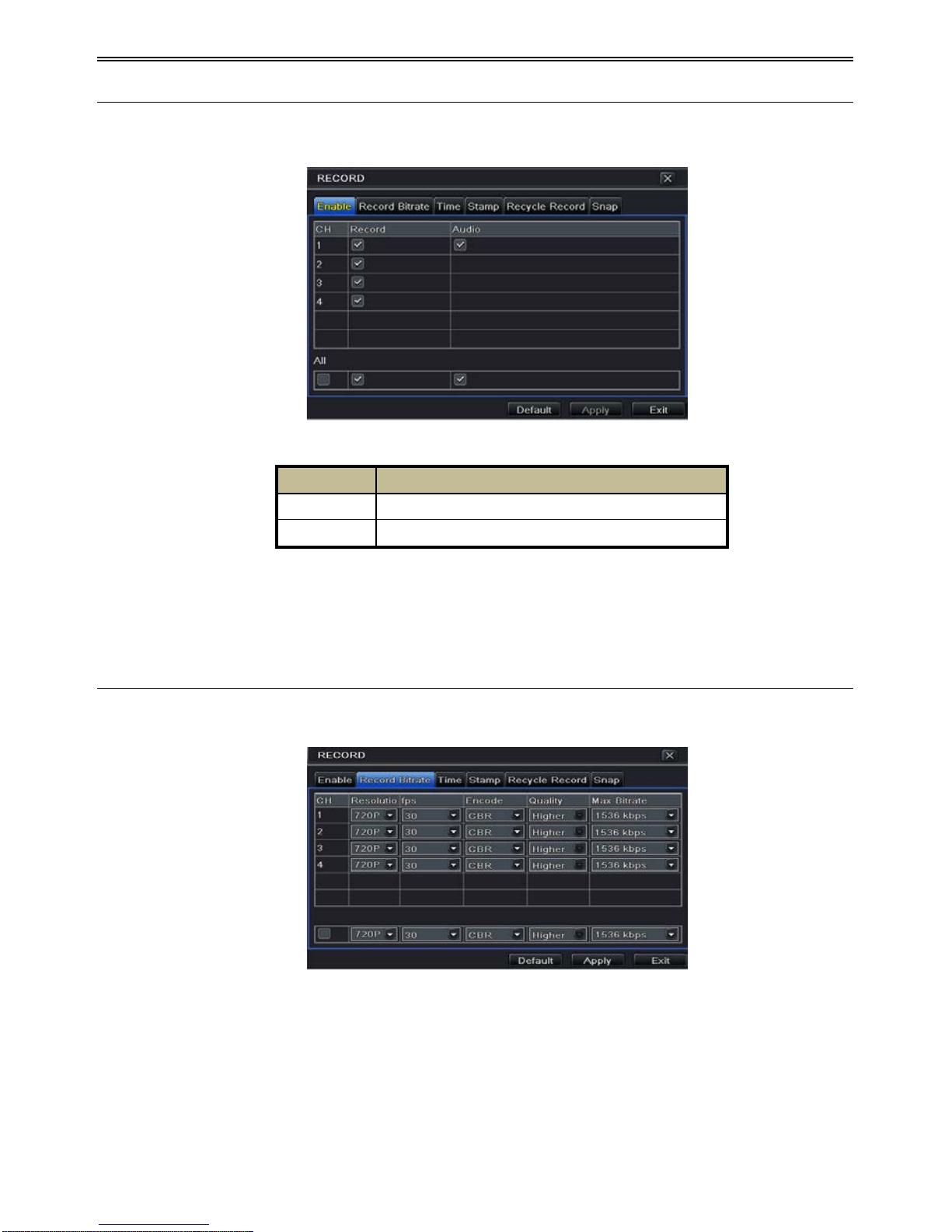
4.3.1 Enable
① Go to MenuSetupRecordRecord interface. Refer to Fig 4-10.
Fig 4-10 Record Configuration-Record
② Checkmark record and audio.
③ Select All to set up the same settings for all channels.
4.3.2 Record Bitrate
① Go to MenuSetupRecord Record Bitrate. Refer to Fig 4-11.
Fig 4-11 Record Configuration-Record Bitrate
② Set up rate, resolution, quality, encode and max bit stream.
③ Select “All” to set the same settings for all ch annels.
④ Click “Apply” button to save the setting.
Parameter
Meaning
Record
To enable/disable recording for the channel
Audio
To enable/disable audio recordin g for the channel

HD-TVI DVR U s er Manual
16
4.3.3 Time
① Go to MenuSetupRecord Time interface to set recording time. Refer to Fig 4-12.
Fig 4-12 Record Configuration-Time
② Set Pre-alarm record time and post-alarm record time. Select “All” to set the same
settings for all channels.
Pre-alarm Record Time: Set the time in seconds to pre-record before the actual
recording begins.
Post-alarm Record Time: Set the time in seconds to post-record after the actual
recording has finished, five options: 10s , 15s , 20s , 30s, 60s, 120s, 180s and 300s .
Expire Time: Set the expirat ion time for recorded video . I f the set date is overdue, the
recorded files will be deleted automatically.
③ Click “Apply” to save the setting.
4.3.4 Stamp
This provides an option to enable or disable the Camera Name and the Time stamp on the
video. The user can also choose a position for the stamp on the screen.
To set up stamp as follows:
① Go to Menu SetupRecordStamp interface. Refer to Fig 4-13.
Parameter
Meaning
Rate
720P/960H/D1: 1-30(NTSC)/1-25(PAL); 1080P: 1-15(NTSC)/1-12(PAL)
Resolution
This series supports D1, 960H, 720P, 1080P
Quality
The higher the value is, the clearer the recorded image is. Six options:
lowest, lower, low, medium, higher and highest.
Encode
VBR and CBR.
Max bit st ream
You shall adjust it subject to the actual network condition.

HD-TVI DVR U s er Manual
17
Fig 4-13 Record Configuration-Stamp
② Checkmark camera n ame and time stamp. Click Setting button to s et up the position of
the stamp. You can drag the camera name and time stamp at random positions. Refer to
below Figures:
Before drag After drag
③ Select “All” to set up all channels with the same parameters.
4.3.5 Recycle Record
This option is used to recycle the HDD space once it is full. If enabled, the system will
automatically delete the old records and recycle the space if it is completely utilized. The
setting steps are as follows:
① Go to MenuSetupRecord Recycle Record interface;
② Checkmark recycle record to activate auto recycling. If the option is disabled or not
selected, the DVR would stop recording once HDD is full.
③ Click “Apply” button to save the setting.
4.3.6 Snap
In this interface, user can set up Resolution, quality, snap interval, snap number.

HD-TVI DVR U s er Manual
18
4.4 Schedule Configuration
Schedule configuration includes two sub menus: schedule and motion.
4.4.1 Schedule
This tab allows defining schedule for normal recording for seven days of a week, 24 hours of a
day. Every row denotes an hourly timeline for a day. Click the grid to do relevant setup. A
highlighted area denotes selected timeline. Operate the following steps to set s chedule:
① Go to MenuSetupSchedule interface. Refer to Fig 4-14.
② Select channel and click “
” button to add a cer tain day schedule. Click “ ” button
to delete the select ed schedule.
If you want to apply the schedule setting of a certain channel to other or all channels, you need
to select channel and click “Copy” button.
Fig 4-14 Schedule Configuration-Schedule
You can also set week schedule by double-clicking in the grinding area. This will take you to
see a dialog box as Fig 4-15.
① Select a day and click “Add” button to set start time and end time. Then click to
save.
② Select other days and add schedule or copy settings from one schedule to the others
under the Apply Settings To item.
Fig 4-15 Schedule-Week Schedule

HD-TVI DVR U s er Manual
19
4.4.2 Motion Schedule
This tab allows to set schedule for motion based recording. The setting steps are as follows:
① Go to MenuSetupSchedule Motion tab.
② The setup steps for schedule for motion based recording are similar to normal schedule
setup. You can refer to 4.4.1 Schedule for details.
Note: The default schedule of motion based recording is 24
ⅹ
7. I f
motion based recording, you must enable motion alarm and set up schedule for motion
alarm (see Chapter 4.5.1 Motion Alarm for more details).
4.5 Alarm Configuration
Alarm configuration includes four sub menus: motion, video loss, other alarm and alarm out.
4.5.1 Motion Alarm
Motion includes two sub menus: motion and schedule. The steps to set motion alarm are as
follows:
① Go to MenuSetupAlarm Motion. Refer to Fig 4-16.
② Enable motion alarm, set alarm hold time which refers to the time till which the system
will wait for further detection of motion. e.g. If the holding time is set to 10 seconds,
once the system detects a motion, it will go into alarm but would not detect any other
motion alarm (specific to channel) until 10 seconds. If there is other motion detected
during this period it is considered it as continuous movement, otherwise it will be
considered as a single motion.
Fig 4-16 Alarm Configuration-Motion
③ Click “Setting” button under the Trigger area. Then a window will pop up as below:

HD-TVI DVR U s er Manual
20
Fig 4-17 Alarm Configuration-Motion Trigger
Buzzer: If selected, the local buzzer would be activated on an alarm.
Show Full Screen: If selected, there will pop up the chosen channel on the monitor on an
alarm trigger.
Email: If selected, the DV R will send an email alert to the preconfigured email addr es s in
case of a motion b as ed alarm from the particu lar input.
Snap: If select ed, the system will snap images of the checked channels on an al ar m and save
them in the HDD automatically.
④ Go to To Record tab. Select reco rdin g chann els. It woul d be recorded in case o f an alarm.
Click OK button to save the setting.
⑤ After clicking Area button, a dialog box will pop up as Fig 4-18.
⑥ In the Area interface, you can d rag slide bar to set the sensitivity value (1-8). The higher
the value is the more sensitive it is to motion. Since the sensitivity is influenced by color
and time (day or night), you can adjust its value according to the practical conditions.
Left click the grid and drag to delete area. Click
icon to set the whole area as
detection area. Click
icon to clear the set d etectio n area. Cl ick icon to test the
sensitivity as per the local conditions. Once motion is sensed, it displays a figure icon.
Click
icon to save the setting. Click icon to exit the current interface.
Fig 4-18 Motion-Area

HD-TVI DVR U s er Manual
21
Note: Prior to setting motion detection field it is recommended that you click
icon to clear the existing field and set afresh.
⑦ Select “All” to set the same settings for all channels.
⑧ Click “Apply” button to save the setting.
⑨ Go to Schedule tab. The settin g steps for schedule fo r motion based alarm are similar to
normal schedule setup (see Chapter 4.4.1 for more details).
4.5.2 Video Loss
This DVR can be set up to detect video loss. The setting steps are as follo ws:
① Go to MenuSetupAlarm Video Loss. Refer to Fig 4-19.
② The setup steps of video loss trigger are similar to motion trigger setting. (See Chapter
4.5.1 Motion Trigger setting for more details).
Fig 4-19 Alarm Configuration-Video Loss
4.5.3 Other Alarm
This tab gives a choice to configure alarm for Disk Full, IP Conflict, the Disconnect event,
Disk Attenuation or Disk Lost.
① Go to Menu Setup Other Alarm. Refer to Fig 4-20.
Fig 4-20 Other Alarm

HD-TVI DVR U s er Manual
22
② Use the dropdown menu and select the event or the alarm.
③ Check the required trigger options.
④ If the selected event is “Disk Full”, then use the drop down box for “Disk Shortage
Alarm” to choose a th reshold value for remaini ng HDD space. If the thres hold value is
reached, the system will trigger the Disk Full Alarm.
⑤ Click “Apply” to save the setting.
4.5.4 Alarm Out
To set up alarm out:
① Go to MenuSetupAlarm Out. Refer to Fig 4-21.
Fig 4-21 Alarm Out
② Checkmark Buzzer and set buzzer alarm hold time. This would trigger the b uzzer when
the system is on an alarm.
4.6 Network Configuration
Network configuration includes six submenus: Network, Sub Stream, Email, Server, N AT and
Other Settings. Network settings must be configured if DVR is used for monitoring over
network.
4.6.1 Network
To set up network:
① Go to MenuSetupNetworkNetwork tab. Refer to Fig 4-22.
② Set HTTP port. The default HTTP port is 80. If the value is changed, you shall add the
port number when typing IP address in IE address blank. e.g. If HTTP port is set to 82
and IP address is http://192.168.0.25
, you should input the following IP address:
http://192.168.0.25:82 into IE browser.
③ Set server port. The default server port is 6036.

HD-TVI DVR U s er Manual
23
Fig 4-22 Network Configuration-Network
④ Connect internet. There are three ways to connect internet.
If you have a DHCP server running and would like your DVR to automatically obtain an
IP address and other network settings, check the checkbox beside "Obtain an IP address
automatically". Then the device will dist ribute IP address, subnet mask, and gateway IP
and DNS server.
If you want to configure your own settings, disable “Obtain an IP address automatically”
item and input the IP address, subnet mask, gateway IP and DNS server.
If you connect internet through PPPoE, disable “Obtain an IP address automatically”
item and check PPPoE ch eckbox and then enter usern ame and pass word. On ce the setup
is completed, your DVR will automatically dial up into your network.
⑤ Test the effectiveness of the network by clicking “Test” button after you set up the
network.
⑥ If the network is well connected, please cl ick “Apply” button to save the setting.
4.6.2 Sub Stream
To set up sub stream:
① Go to MenuSetupNetwork Sub Stream interface. Refer to Fig 4-23.
Fig 4-23 Network Configuration-Sub Stream

HD-TVI DVR U s er Manual
24
② Select fps, resolution, quality, encode and max bit rate
③ Select “All” to set the same settings for all ch annels.
4.6.3 Email
To set up Email:
① Go to MenuSetup NetworkEmail i nterface. Refer to Fig 4-24.
Fig 4-24 Network Configuration-Email
② Set SMTP Server and port.
SMTP Server/Port: The name and port number of SMTP server. You can set up SSL
check (such as Gmail) according to actual needs.
③ Set sender’s address and pas s word.
④
Set receiver’s email address and click “Test” button to test the validity of th e mailbox.
Attachi ng image: If selected, the system will attach images when sendin g emails.
4.6.4 Server
This function is mainly used for connecting ECMS/NVMS. The setting steps are as follows:
① In the server in terface, select “Enable” as shown in the Fig 4-25.
② Check the IP address and port of the transfer media server in the ECMS/NVMS. The
default server port for auto report is 2009. If it is modified, please go into the transfer
media interface to check.
Parameter
Meaning
FPS
Range from: 1-25.
Resolution
Support C IF.
Quality
The quality of the clients’ image. The higher the value is, the clearer the
record image. Six options: lowest, lower, low, medium, higher and highest.
Encode
VBR and CBR.
Max bit rate
Range from: 256~1792kbps.

HD-TVI DVR U s er Manual
25
Fig 4-25 Network Configuration-Server
③ Enable the auto report in the ECMS/NVMS when adding a new device. Then input the
remaining information of the device in the ECMS/NVMS and self-
define a device ID.
④ Input the above-mentioned ser ver IP, server port and device ID in the server inter face.
Then click “Apply” button to save the setting. Now, the ECMS/NVMS system will
automatically con nect this device.
4.6.5 NAT
① Go to MenuSetup NetworkNAT interface. Refer t o Fig 4-26.
② Enable NAT and input the NAT Server (The default NAT Server is www.autonat.com ).
③ Click “Apply” to save the settings.
Fig 4-26 Network Configura tion-NAT
4.6.6 Other Settings
If your DVR is set to use PPPoE as its default network connection, you may set up DDNS to
be used in connection. The setting steps are as follows:
① Enable DDNS server.
② Select DDNS server.
③ Enter user name, password and host domain name of the registered webs ite.
④ Click “Test” button to test the effectiveness of the relevant information.

HD-TVI DVR U s er Manual
26
⑤ Click “Apply” button to save the setting.
Fig 4-27 Network Configura tion-Other Se ttings
Note: The domain name selected by user is a banding domain name of DVR. User
should logon the website provided by the server supplier to register a user name and
password and then apply for a domain name online. After the successful application,
user can access the device from the IE client by inputting that domain name.
Enable UPnP: Select UPnP here and then enable UPnP function in your router. Therefore,
there is no need for you to forward LAN IP address and port in the router in connection of
internet. After that, you can check the WAN IP address in the router.
Domain name Regis tration (Take www.dvrdydns.com for example)
1. Input www.dvrdydns.com in the IE address bar to visit its website. Then click
“Registration” button to register as shown below.
2. Create domain name.

HD-TVI DVR U s er Manual
27
3. After you successfully request your domain name, you will see your domain in the list.
DVR Setting
Connect DVR to the Network Client.
1. Go to Main menuNetworkOther Settings, checkmark DDNS, select “dvrdydns” at the
DDNS Sever pull down list box and input user name and password.
2. Go to configuration interface of the router to map the server port and IP address (if the user
enables UPnP function, he can skip this step). Click Save button to save the setti ng.
3. Login IE browser and input registered domain name “http://www.xxx.dvrdydns.com”,
connect to DVR client.
You can also quickly register the domain name in this interface.
1. Set the IP address manually in the network tab and then click “Other Settings” tab.
Check “DDNS”.
2. Select “www.autoddns.com” in DDNS Type column as shown above.
3. Enter the host name at random, like 123.
4.Click “Register” to register the domain name. When the successful prompt pops up, it means
you are successfully register your domain name.
If your IP address is not WAN IP address, you should forward your IP address and port in your
router or enable UPNP function both in router and DVR. Then you can use the domain name

HD-TVI DVR U s er Manual
28
plus HTTP port to access your DVR.
DDNS server
DDNS server
Website provided by dynamic domain name supplier. The optional:
www.meibu.com, www.dyndns.com, www.dvrdydns.com, www.
autoddns.com, www.no-ip.com and mintdns type.
User name
User name for log in the website of domain name supplier.
Password
Password for log in the website of domain name supplier.
Host domain
The domain name user registered at the supplier’s website.
Update interval
The interval time of upgrading DVR IP address.
4.7 User Management Configuration
This tab allows you to add normal or advanced users. To add user and set up us e r authority:
① Go to MenuSetupUsers. Refer to Fig 4-28.
Fig 4-28 User Management Configuration
② Click Add button to display a dialog box as Fig 4-29.
Fig 4-29 Add-General

HD-TVI DVR U s er Manual
29
③ In General tab, input username, password and select user type. You can also check
“Binding PC MAC Address” and input this address.
④ Click “OK” to save the set ting.
Note: When the default value of binding PC MAC Address is 0, the user is not bound
with the specified computer. If the bind option is used, the user would be able to log
into the DVR only through the specific computer (carrying the MAC address).
⑤ Select Authority tab and assign the operation rights for particular user. Refer to Fig 4-30.
⑥ Click OK to save the setting.
Fig 4-30 Add User-Authority
To delete user:
① Go to MenuSetupUsers interface.
② Select the add ed user you want to delete and then click “Delete” button.
To modify user:
① Go to MenuSetupUsers interface.
② Select the added user you want to modify and then click “Modify” button to do the
relevant operat ion.
To change user password
① Go to MenuSetupUsers interface.
② Select the add ed user you want to change it s password and then click “Change
Password” button.
4.8 P.T.Z Configuration
P.T.Z configuration includes two submenus: serial port and advanced.
Serial port settings are as follows:
① Go to MenuSetup P.T.Z Serial Port interface. Refer to Fig 4-31.

HD-TVI DVR U s er Manual
30
Fig 4-31 P.T.Z Configuration-Serial Port
② Select “Enable” and set up the value of address, baud rate and protocol according to the
settings of the speed dome.
③ Select “All” to set the same settings for all ch annels.
Advanced settings include preset setting, cruise setting and track setting.
Go to MenuSetup P.T.Z Advanced. Refer to Fig 4-32.
Fig 4-32 P.T.Z configuration-advanced
To set up preset:
Parameter
Meaning
Address
The address of the PTZ device.
Baud rate
Baud rate of the PTZ device. Range form: 110, 300, 600, 1200, 2400,
4800, 9600, 19200, 34800, 57600, 115200, 230400, 460800, 921600.
Protocol
Communication protocol of the PTZ device. Range from: NULL,
PELCOP, PELCOD, LILIN, MINKING, NEON, STAR, VIDO, DSCP,
VISCA, SAMSUNG, RM110, HY, N-control.
Simulative
Cruise
If enabled, n o matter whether the PTZ device supports cruise or not, t he
presets will cruise.

HD-TVI DVR U s er Manual
31
① In the Advanced interface, click preset “Setting” button to see a dialog box as Fig 4-33.
Fig 4-33 Advanced-Preset Setting
② In the preset setting tab, enable preset, set the preset name and t hen click preset
“Setting” button.
Fig 4-34 Preset Setting
③ Control the dome by rotating up, up left, down, right down, left, left down, right and up
right and adjust the rotate speed and the value of zoom, focus and iris of the dome.
④ Select the serial number of the preset point. Click
button to enable the PTZ wiper
and click
button to enable the PTZ light.
Note: PTZ must support wiper and light button and these two buttons are just available
when selecting PELCOP or PELCOD.
⑤ Click Save button to save the setting. Click icon to hide the tool bar. Right click to
view this bar again. Click
icon to exit the current interface.
⑥ Return to the Advanced-Preset Setting interface and click OK button to save the setting.
To set up cruise:
① In the Advanced interface, click cruise “Setting” button to see a window as shown in Fig
4-35.

HD-TVI DVR U s er Manual
32
Fig 4-35 Cruise Setting
② Click Add button to add cruise line in the list box (8 cruise lines can be added at most).
③ Select a cruise line and click Setup butto n to see a dialog box as Fig 4 -36.
Fig 4-36 Modifying Cruise Line
④ Click A dd icon
to set the speed and time of preset point. Select a preset point and
then click Delete i con
to delete that preset point. Click Modify icon to
modify the setting o f a preset point. Us er can click
those icons to
adjust the position of preset point. Click Preview button to preview the cruise line. Click
OK button to save the setting.
To set up track:
① In the Advanced interface, click track “Setting” button to see a dialog box as Fig 4-37.
② Control the dome by rotating up, up left, down, right down, left, left down, right and up
right and adjust the rotate speed and the value of zoom, focus and iris of the dome.
③ Click Start Record button to record the move track of PTZ. Click this button again to
stop record.
④ Click Start track button to play recorded track. Click this button again to stop playing.
⑤ Click
icon to exit the current interface.

HD-TVI DVR U s er Manual
33
Fig 4-37 Track Setting
4.9 Advanced
Advanced configuration includes three submenus: reset, import/export and Block/Allow list.
4.9.1 Reset
Reset all settings of the device.
4.9.2 Import/Export
Export the data files into mobile storage devices for backup and then import specified data
files from mobil e storage device to DVR.
4.9.3 Block/Allow List
Fig 4-38 Block /A llow List
Here authorized user can prohibit computer users within a certain IP address range from
accessing to DVR or allow computer u s er s within a certain IP address range to access DV R .
E.g. if an admin user doesn’t want computer users within IP address range from
192.168.000.002 to 192.168.000.004 to access the DVR, he can check Block list option, and
then input such IP address range. If it is required that computer users within a certain IP
address range acces s D VR, they can check Allow List option and then do the required setting.

HD-TVI DVR U s er Manual
34
5 Search, Playback & Backup
Search configurat ion includes four su bmenus: time search, event search, file manag ement and
image.
5.1 Time Search
① Go to MenuSearch Time Search. Refer to Fig 5-1.
Fig 5-1 Search Configuration-Time Search
② Select date and channels on the right hand side and press the “Search” button. A date
with highlighted borderline indicates presence of data.
③ Set the start time by clicking a particular grid or by entering the specific value in the
start time field.
④ Select the channel display mode and click Play button to play record. Use the playback
toolbar to con tr ol t he playback.
To set backup during a certain period in the playback interface:
Select the start time by dragging the slider and click
icon. Then select the end time and
click this icon again to confirm th e record period. Next, click
icon to backup the record
during this pe ri o d.

HD-TVI DVR U s er Manual
35
5.2 Event Search
① Go to MenuSearchEvent Search button. Refer to Fig 5-2.
Fig 5-2 Search Configuration-Event Search
② Select date and channels on the right hand side. A data with highlighted borderline
indicates pr esence of data.
③ Checkmark Motion or All accordingly.
④ Click Search button to display the searched event information in the event list box.
⑤ Double check a certain record file to playback.
5.3 File Management
① Go to MenuSearchFile Management interface. R efer to Fig 5-3.
Fig 5-3 Search Configuration-File Management
② Select date and channels. The date with highlighted borderline indicates presence of

HD-TVI DVR U s er Manual
36
data.
③ Click Search button to display the searched files in the file list box.
④ Use “All” button to lock/unlock or delete all files in the file management column.
⑤ Double click an unlocked item to play.
Lock: Select a file and click Lock button to lock this file, after that, that file will not be
deleted or covered .
Unlock: Select a locked file and click “Lock” button to unlock this file.
Delete: Select an unlocked file and cli ck “Delete” button to d elete this file.
5.4 Search by Image
① Go to Menu Search I mage tab.
② Select data and channels on the right hand side.
③ Press “Search” button to search for a recorded image.
④ Once an alarm image has been identified, the user can double click the image to play
recording.
Fig 5-4 Search Configuration-Image
Lock: Select the image and click “Lock” button to lock this image.
Save: Click “Save” button to copy the image on the HDD.
Save All: Click “Save All” button to copy all images on the HDD.
5.5 Backup
This unit supports backup by USB Flash. You can also make backup by IE browser via
internet (see section 7.3.2 Remote backup).
① Insert USB storage device and then go into backup configuration. Refer to Fig 5-5.
② Set the start & end time, select channels and click Search button to display the searched
data in the data backup list box.

HD-TVI DVR U s er Manual
37
Fig 5-5 Backup Configuration
③ Select a required file or checkmark “All” to select all data files. Click Backup button to
display Backup information window.
④ In the backup information interface, you can check the r elevant information of backup
files, storage type, save file type, etc. Then click Start button to start b ackup.
Note: If the backup files are saved in DVR format, please check backup player. Only
this player can play these files in DVR format. If the backup files are saved in AVI
format, you can play these files with common media player.

HD-TVI DVR U s er Manual
38
6 Manage DVR
6.1 Check System Information
Check system information includes six submenus: system, event, log, network, online user and
record.
6.1.1 System Information
In this interface, you can ch eck t he h ard ware versi on , M CU versi on , ker nel versio n, devi ce ID,
etc.
6.1.2 Event Information
In this interface, you can search for events l ike motion and video loss. The utility provides an
interface to have a date b ased and a channel based search . This report can fu rther be saved on
a USB flash drive as an html file using the export button.
6.1.3 Log Information
In this interface, you can search for relevant logs as per set date and event which includes
Operation, Setup, Playback, Backup, Search, Check Information and Error. This report can
further be saved on a USB flash drive as an html file using the export button.
6.1.4 Network Information
In this interface, you can check relevant parameters of network.
6.1.5 Online Information
In this interface, you can check the details of the connected online users.
Refresh: Refresh the current interface.
Disconnect: Disconnect the on line users to access DVR . I f this function is used by the admin,
the particular PC will not be able to access the device for five minutes.
6.1.6 Record Information
In this interface, a user can check resolution, ftp and record status including motion recording,
manual recording or schedule recording.
6.1.7 QRCODE
User can quickly access the mobile client by scanning QRCODE. Go to Main
menuInformationQRCODE tab. Refer to Fig 6-1.

HD-TVI DVR U s er Manual
39
Fig 6-1 Information Configuration
In this interface, you can scan the QRCODE through the mobile phone. Refer to Fig 6-2.
Fig 6-2 Information Configuration-QRCODE
6.2 Disk Management
To format the disk
① Go to disk management interfa ce.
Note: please format the hard disk before record.
② Click Refresh button to refresh the disk information in the list box.
③ Select a hard disk an d click Format button to start format.
Note: All recorded files in the hard disk will be lost after formatting.
To check other informatio n of disk
After you Go to Disk ManagementAdvanced tab, you can check model, S/N, firmware,
health status of the disk in this interface. You also can monitor the temperature, in tern al circu it,

HD-TVI DVR U s er Manual
40
dielectric material o f the di sk, analysis the potential problems of th e disk and warn s o as to
protect its data.
6.3 Upgrade
At present, it only supports USB update. Get the software from your vendor when there is a
new software version.
The upgrade steps ar e as fo llows:
① Copy the upgrade software which gets from vendor into the USB storage device.
② Connect the USB flash drive to the USB port.
③ Enter MenuUpgrade tab. You will see the upgrade software name displaying in the
upgrade list box.
④ Select that software and then click Upgrade button. The system will be upgraded
automatically.
Note: Please wa it for a while when the s ystem reboots. Any power interruption is not
allowed during upgrading.
6.4 Logoff
A log off dialogue box will pop up by clicking Log off icon. Then click OK button to confirm
to log o ff. If you want to log in again, click
icon to enter user name and password to
re-login.

HD-TVI DVR U s er Manual
41
7 Remote Surveillance
7.1 IE Remote Surveillance by NAT
7.1.1 NAT Settings
① The DVR shall be powered on and connected to the network.
② Go to MenuSetupNetwork. You can obtain the IP address, Subnet Mask and
Gateway automatically. You can also manually input them according to the configuration
of PC. And the IP address shall be in the same network segment as the network which is
used.
③ Set the preferred or alternative DNS Server (Please refer to 4.6.1 Network for details) .
④ Go to MenuSetupNetworkNAT tab.
⑤ Enable NAT and input the NAT Server (The default NAT Server is www.autonat.com) .
⑥ Click “Apply” to save the parameters (Please refer to 4.6.5 NAT for details) .
7.1.2 NAT Acces s
After finishing the NAT settings, you can enter the NAT Server on the PC (Input
http://www.autonat.com to go to the IE client) . If you are the first ti me to access the NAT, the
network will dow nloa d t he ActiveX automatically.
Note: If you cannot download and install ActiveX, please refer to FAQ Q8.
After installing ActiveX successfully, it will pop up the login box:
Serial No: The MAC add r es s of the DVR(Go t o MenuInformationNetwork to check the
MAC address of the DVR).
User Name: The login username of DVR. The default username is admin.
Password: The login password of DVR. The default password is 123456.

HD-TVI DVR U s er Manual
42
7.2 IE Remote Surveillance via LAN & WAN
In order to view the DVR from a network it may be connected to a LAN/WAN or internet. The
network setup should be done accordingly. Please refer to 4.6 Network Setup. This DVR
supports IE br owser, on Windows XP a nd Vis ta pl a tform.
7.2.1 Via LAN
① Enter into the DVR’s Main MenuSetupNetwork i nterface to inpu t IP address,
Subnet Mask, etc .If using DHCP, please enabl e D HCP in both the DVR and the router.
② Enter Record Setup to set network video parameters like resolution, frame rate etc.
③ Open IE on a computer on the same network. Input the IP address of the DVR in IE
address bar and press enter.
④ IE will download ActiveX component automatically. Enter the username and password
in the subsequent window
Notice: If HTTP port is not 80, other number instead, add the port number after IP
address. For example, set HTTP port as 82, input IP address like 192.168.0.25:82.
User name and password here are the same with that used on the DVR. The default
username is “admin” and the default password is “123456”.
7.2.2 Via WAN
There are two ways for t he DVR to connect t o i nternet.
1. Conne c t the DVR to intern e t through route r or virtual se rver
① Enter into the DVR’s Main MenuSetupNetwork interface to input IP address,
Subnet Mask, etc. If using DHCP, please enabl e D HCP in both the DVR and router.
② Forward IP address and port number in Virtual Server setup of the router or virtual server.
Configure the firewall to allow accessing the DVR (If the user has enabled the UPnP
function in both the DVR and router, he can skip this step) .
③ If users want to utilize dynamic domain name, please apply for a domain name in a DNS
server supported by the DVR or router. Then add to the DVR or router.
④ Open IE browser, input IP address, or dynamic domain name and enter. If HTTP port is
not 80, add the port number after IP address or domain name.
⑤ IE will download ActiveX automatically. Then a window pops up and asks for user
name and password. Input name and password correctly, and enter to view.
Note: If you cannot download and install ActiveX, please refer to FAQ Q8.
2. Connect the DVR to internet directly
① Enter into the DVR’s Main MenuSetupNetwork in ter face to e nab le PPP oE and then
input user name and password received from your ISP. Next, click ‘Apply’. The DVR

HD-TVI DVR U s er Manual
43
will connect to the server and would give a confirmation message.
② When accessing the re mote interf ace of DVR, user can in put WAN IP to access directly
(user can enter i nto Main menuInformationNetwork interface to ch eck IP address).
The browser will download Active X control.
③ The following setting steps are as the same as ④ and ⑤ in Point 1.
7.3 Remote Surveillance through Apple PC
Note: Because the current plug-in version of client end just only supports 32-bit mode,
so the safari browser shall start 32-bit mode. If the browser is the earlier MACOS
version, the default setting is 32-bit mode and the setting can be skipped.
The setting steps are as foll ows:
① Right click safari icon and select “Show in Finder”.
② Select ApplicationsRight click “Safari. App”Select “Get Info”.
③ Select “Open in 32- bit mode”.
7.3.1 Via LAN
① After starting Apple computer, click Apple icon. The following window will pop up.
Please select “Syst em Preferences” “In ternet &Wireless” “Network”.
② Go into Network interface and then click “Ethernet Connected” to check the internet
connectio n of Apple PC.

HD-TVI DVR U s er Manual
44
③ After acquiring the IP address, Subn et Mask and so on, please Go to the DVR’s Main
MenuSetupNetwork interface to manually input IP address, Subnet Mask and
Gateway according to the configuration of PC. The network segment should be the same
as the PC. If using DHCP, please enable DHCP in the DVR and router.
④ After the above information is completed, you can enter LAN IP and http port in the
Safari browser. For example: input http://192.168.1.100:81(here 192.168.1.100 is LAN
IP o f DVR, 81 i s the htt p port of DVR), and click “
”button. Then the browser will
download Active X control as shown below:
⑤ Click icon and then select the Active X control, the welcome interface will be
shown. Click “Continue” “Install” button, the following window will pop up:
Input the name and password of Apple PC and then click “OK” to install this Active X
control.
⑥ After finishing installing the Active X control, please quit from the Safari browser. Right
click Safari icon on the desktop and then select “Quit” button to quit the browser. Then
restart Safari browser. Input the IP address and http port to go to the login interfac e of
DVR.
7.3.2 Via WAN
There are also two ways for DVR to connect to Internet.
1. Conne c t the DVR t o i nternet through router or virtual server

HD-TVI DVR U s er Manual
45
① The network setups are the same as step one to step four of point 1 on WAN of IE
remote surveillance.
② Enter WAN IP and http port in the Safari browser to install the Active control. The
concrete steps ar e the same as step 5 and 6 of Chapter 7.2.1.
2. Connect the DVR to internet directly.
① The network setups are the same as step one of point 2 on WAN of IE remote
surveillance.
② Enter WAN IP and http port in the Safari browser to install the Active control. The
concrete steps are the same as step 5 and 6 of Chapter 7.2.1.
7.4 The Remote Live Preview
Fig 7-1 Remote Live Preview Interface
1
Channel indicator
2
Screen display mode
3
Volume
4
Start recording
5
Snapping picture
6
Start IE record
7
Bidirectional talk
8
Playback
9
PTZ control
10
Master/sub stream status
Note: Click
button to start recording. The record file will be saved in user’s P C .
Screen displ ay mode :
Click the icon beside the screen display mod e to select channels.

HD-TVI DVR U s er Manual
46
Snap pictures
Click “Snap” icon to automatically capture pictures and save those pictures in the
computer. You can set up the save pat h for th ose p icture i n the Re mote Pr eview inter face
Configuration Local configuration.
PTZ control
Please connect speed dome to the device via RS485 firstly, make sure the protocol of the
speed dome is supported by the device and set the relative parameters manually. User can
control the dome up, down, right, left or stop rotating on Control Center, adjust rotation speed,
Iris and zoom, focus on the do me, and set the presets, etc.
Buttons definition:
Buttons
Description
to rotate the d ome upwards. to rotate th e dom e diagon ally
up-left.
to rotate th e dome di agonally u p-right to rotate
the dome downwards.
to rotate the dome diagonally
down-right to rotate the dome diagonally down-left to
rotate the dome towards left.
to rotate the dome towards
right to stop rotating the dome.
Drag the scroll bar to adjust rotating speed of the dome.
'Iris' but ton. Click
button near 'Iris' button to increase light
of the dome. Click
button near 'Iris' button to decrease
light of the dome.
'Zoom' button. Click
bu tton ne ar 'Zoom' but ton to zoom in
the locale picture of this camera. Click
button near 'Zoom'
button to zoom out the locale picture of this camera.
'Focus' button. Click
button near 'Focus' button to have
long focus. C lick
b utton near 'Focus' button to have sh ort
focus.
Go to the Preset.
Select and do auto cruise.
Track
Auto scan
Wiper button
Light button
Click the right mouse on the live interface. This will take you to a pull-down menu.

HD-TVI DVR U s er Manual
47
Fig 7-2 Right Key Sub Menu
Stream: This DVR supports master stream and su b stream. Mast er stream has higher frame
rate, max 25FPS(PAL)/30 FPS(NTSC)for every channel, but it needs higher network
bandwidth simultaneously. Sub stream has l ow frame rate, max 6FPS (PAL)/7FPS(NTSC)
for every channel, it requires low network bandwidth. Therefore, you can select the stream
according to your bandwidth.
All to master/sub stream: Set all chann el to master stream or sub st r eam.
Enable a udio: Enabl e or disenable audio.
Full scree n: The live preview picture will display with full screen and the tool bar will be hid.
Double click left mouse or click right mouse to return.
Zo o m in : Single chann el large screen electro nic amplific atio n. Click th e chann el which needs
to be zoomed. Right click to select zoom in button to zoom in the image. Double click or right
click to exit.
7.5 Remote Playback & Backup
7.5.1 Remote Playback
Click button to go into record playback interface. Refer to Fig 7-3.
Select the recor d date and channels and d ouble-click the file name in the record file list box.
Then you can pl ay that file and preview the p icture.
Fig 7-3 Play Record File Interface

HD-TVI DVR U s er Manual
48
This DVR supports remote time search, event search and file management.
By Time Search:
① Go to SearchTime Search. Refer to Fig 7-4.
② The highlight date in the area ② indicates recorded data. Select the date in ar ea ② and
record channels in area ③.
③ Click “Search” button. The record data will be displayed in the data information list box.
④ Set the data playing time and display mode in the area ① as required.
⑤ Click “Play” button to playback. 8 CH DVR only supports single channel display.
Fig 7-4 Time Search Interface
⑥ Click the relevant buttons in the interface for operat ion, like FF, pause, change channel
mode, etc. Refer to Fig 7-5.
Fig 7-5 Time Search Playback

HD-TVI DVR U s er Manual
49
By Event Search:
① Go to SearchEvent Search interface. Refer to Fig 7-6.
② Click the highlight date and select reco rd channels.
③ Checkmark the event type: motion.
④ Click “Search” bu tton.
⑤ Double-click certain item to play.
Fig 7-6 Event Search Interface
File Management
① Go to SearchFile Management interface. Re fer to Fig 7-7.
Fig 7-7 File Management Interface
② Select highli ghted date and channels.
③ Click “Search” bu tton to search the recorded files.
Lock: Sel ect certain file item in the file list box and then click “Lock” button to lock this file
that ca not be delet ed or overlaid.
Unlock: Select a locked file and th en click “Unlock” button to unlock this file.

HD-TVI DVR U s er Manual
50
Delete: Select an u nlock file and then click “Delete” button to delete this file from file list.
7.5.2 Remote Backup
Click Backup button to go to backup interface. Pl ease refer to Fig 7-8.
Fig 7-8 Remote Backup Interface
① Select channels , set the start and end time and then click “Search” button to display the
file information in the file list box.
② Select backup files and click “Browse” bu tton to set the save pat h. Then click “Backup”
button to start backup. The backup files will be saved on user’s PC.
7.6 Remote System Configuration
You can do remote setup of the device which includes functions like basic configuration, live
configuration, record configuration, schedule configuration, alarm configuration, network
configuration, PTZ configuration and user configuration. You should select an option from the
menu list on the left and then set up the relative parameters. Only one user can do
configuration setup at a given point of time. Click Config tab to go to the below in terface
The sub menu list and the option s in every menu are si milar to that of the DVR. Please refer to
Chapter 4 Main Menu Setup Guide for more details.
Fig 7-9 Remote Menu Setup

HD-TVI DVR U s er Manual
51
7.7 Tools
Click on the t ool’s tab to access th e Disk Management too l. The user can view the s tatus of
the hard drive(s) , view/change the read write properti es and format the hard dr ive(s).
7.8 Remote Management
The I nfo in terface pr ovides a web b ased inter face to access t he ge neral i nformation pert aining
to the DVR’s settings. The interface includes five submenus: System, Event, Log, Network
and Online use r s .
Note: There may be subtle differences with respect to functions of remote surveillan ce
between through IE and through Apple PC. Here we only take IE remote access for
example.

HD-TVI DVR U s er Manual
52
Appendix A FAQ
Q1. Why the DVR doesn’t turn o n after connecting to the power?
a. The power adapter could have gone bad. Please change a new po w er adapter.
b. The power from the adapter may be not enough for operating the DVR. Please use the
power adaptor supplied along with the DVR.
c. It could be a hardware problem.
Q2. The DVR LED turns on but there is no output, why?
a. The power from th e adapter may be not enough for operating the DVR. Please use the
power adaptor supplied along with the DVR.
b. It could be a wiring issue. Please check t he connection fo r th e s ame.
c. Check the monitor settings.
Q3. Why are no images displayed on few or all channels of the DVR?
a. It could be a wiri ng issue. Please check the cable and the por ts of the cameras and DVR .
b. The prob lem can also be related to camer as. Please check th e same.
c. Please make su re th at t he ch annels are not programmed as hidden channels and check the
status from admin login.
Q4. The HDD cannot be found.
a. The power from the adapter may be not enough for operating the DVR. Please use the
power adaptor supplied along with the DVR.
b. It could be wiring issue. Please check the power and data cables of the HDD.
c. The HDD could have gone bad. Change a new one.
Q5. The DVR cannot record.
a. Make sure the HDD was formatted prior to use.
b. Maybe the user hasn’t enabled the record function or has done incorrect setup. Please
refer to Chapter 5.
c. Maybe HDD is full and thus the DVR is not able to record. Check HDD information
from Disk Management and if required , please enable the recycle function.
d. The HDD could have gone bad. Please change another one.
Q6. Mouse d o esn’t work.
a. The mouse should be connected to the USB port at the rear side.
b. After connecting the mouse, allow the DVR to detect the mouse for seconds. If not detected,
try restarting the DVR.
c. The mouse may be incompatib le. Please change a mouse.
Q7. ActiveX control can not be downloade d.

HD-TVI DVR U s er Manual
53
a. IE browser blocks ActiveX. Please do setup as per the steps mentioned below.
① Open IE browser. Click ToolsInternet Options.
② Select SecurityCustom Level. Refer to Fig 7-1.
③ Enable all the sub options under “ActiveX controls and plug-ins”. Refer to Fig 7-2.
④ Then click Ok to finish setup.
b. Other plug-ins or anti-virus blocks ActiveX. Please uninstall or do the required settings.
Fig 7-1 Fig 7-2
Q8: DVR displays “please wait…”all the time.
a. HDD power cable and data cable may not be well connected. Please check the
connections for HDD.
b. It is also possible that the DVR was forced t o stop because HDD has a bad sector and i t
may have caused th e s yste m to halt. Check with a good known HDD or try formatting the
existing HDD.
Q9: How to input password and digital numbers?
Click the password or the input box to pop up a small keyboard. Please select characters to
be input (the initial password is 123456), or you can use the digital keys on the front panel, or
the digital keys on the remote controller.

HD-TVI DVR U s er Manual
54
Q10: A hard disk is be ing ident ified as a new device how ever it was being used with
another D VR o f same model. Should it be formatted prior use?
It is possible to migrate an HDD from one DVR to another provided that the DVRs are of the
same model and that the HDD being migrated would be used as the sole disk in the new DVR.
However in cases where the new DVR already contains a HDD, the migrated disk being
installed would have to be formatted. In general migrating disks from one DVR to another is
not recommended.
Q11: What is the minimu m configuration required for remote monitoring?
PC Module
Parameters
CPU
Intel Cele r on 2.4G
Motherboard
Intel 845
HDD
80G
RAM
512M
VGA
NVIDIA GeForce MX440/FX5200 ATIRADEON 7500/X300
OS
Windows 2000(SP4 above) /Windows XP(SP2 above) /VISTA
DirectX
9.0
Q12: How to handle the sit uation that the codec Control is blocked when downloadi ng in
the VISTA or Win7 system?
This problem can be fixed in two ways:
a. Enter Control PanelUser Accoun t and Family Safety User Account Control (refer to
the following figure) and click Turn User Account on or off. Cancel Use User Account
Control (UAC) to help protect your computer.
b. Right click IE browser (refer to the following figure) and select Run as admini strator to
run browse r.

HD-TVI DVR U s er Manual
55
Q13. How to play the backu p file?
Insert your USB device where t he backup files are saved in the USB port of PC. If your files
are saved in DVR format, you must have already downloaded the backup player box before
doing backup. Then double click to open your USB disk to find your backup files and backup
player. Double click
icon to install backup player. After you install it, open this
player and click “Open Path” button to open your backup file. Next, click
play button to
play the backup file. Double click the image and then right click to enable audio. If you save
your backup files in AVI format, you can directly open your file by using the media player
which supports this format.

HD-TVI DVR U s er Manual
56
Appendix B Calculate Recording Capacity
Users can calculate the size of hard disk according to the saving time and DVR recording
settings. The DVR uses fixed vi deo bit rate. The below are the details at different settings.
Resolut
ion
Frame Rate
Totally(FPS)
Video Quality
Bit Ra te
(kbps)
Used
Space(MB/h)
720P
25(PAL)/
30(NTSC)
Highest
6144
2700
Higher
5420
2250
Medium
4096
1800
Low
3072
1350
Lower
2048
900
Lowest
1024
450
1080P
12(PAL)/
15(NTSC)
Highest
12M
2700
Higher
9M
2025
Medium
7M
1575
Low
6M
1350
Lower
4M
900
The calculation format is: Total Recording capacity =Used space per hour (MB/h)
(coverage rate of hard disk) × recording time (hour) × channe l numbers
For instance, one customer uses NTSC cameras, set resolution to 720P, video quality to
Lowest, frame rate to 30 fps for enabling total 4 channels. He wants the unit to record
continuously in a month. Below is the calculation:
Total Recoding capacity =450 (mb/h) X 24(hours/day) X30(days) X4(channels)= 1296000
(MB)≈1266(GB)
Therefore, you need to install one 2 TB SATA HDDs for recording in one month.

HD-TVI DVR U s er Manual
57
Appendix C Compatible Devices
1. Compatible USB drive after test.
Brand
Capacity
SSK
512MB, 1G, 2GB
Netac
4GB
Kingston
2GB
Aigo
2GB
Smatter vider
1GB
SanDisk
4GB
2. Compatible HDD list
Brand
Capacity
Seagate Barracuda
80G/160G/250G/320G /1.5T/2TB/3TB
Seagate SV35.3
1T
Seagate Pipeline HD.2
500G
Maxtor Diamondmax
160G
HITACHI Deskstar
80G/160G
Western Digital
160G/250G/320G /1.5T/2TB/3TB
Samsung HD161HJ
160G

HD-TVI DVR U s er Manual
58
Appendix D 4 CH Specifications
Compression format
H.264 High Profile
Video output
VGA × 1, HDM I× 1
Video Input
4CH 1080P@25/30FPS, 720P@20/30/50/60FPS, 960H,
D1 video input
HDMI/VGA Resolution
1080 × 1920/1280 ×1024/ 800 × 600
Record Resolution 1080P (1920 × 1080), 72 0P (1280 × 720), 960H, D1
Display Frame Rate
100FPS (PAL), 120 FPS (NTSC )
Record Frame Rate
720P/960H/D1: 100FPS (PAL), 120FPS (NTSC)
1080P: 50FPS(PAL), 60FPS(NTSC)
Audio Input
RCA × 1
Audio output
RCA × 1
Record Mode
Manual / T imer / Motion de tection
Simplex/Duplex/Triplex
Pentaplex
Network Interfac e
RJ45 (LAN, INTERNET)
PTZ control
YES
Communication interface
RS485, USB2.0 × 2 (one for b ackup, another for USB
mouse)
Disk info
SATA × 1
Remote controller
YES
Power consumption
< 9W(without HDD)
Power Supply
DC12V
Temperature
0℃-50℃
Humidity
10%-90%

HD-TVI DVR U s er Manual
59
Appendix E 8 CH Specifications
Compression format
H.264 High Profile
Video output
VGA × 1, HDM I× 1
Video Input
8CH 1080P@25/30FPS, 720P@20/30/50/60FPS, 960H,
D1 video input
HDMI/VGA Resolution
1080 × 1920/1280 ×1 024/ 800 × 600
Record Resolution 1080P (1920 × 1080), 72 0P (1280 × 720), 960H, D1
Display Frame Rate
200FPS (PAL), 240FPS (NTSC)
Record Frame Rate
720P/960H/D1: 200FPS (PAL), 240FPS (NTSC)
1080P: 100FPS (PAL), 120FPS ( NTSC)
Audio Input
RCA × 1
Audio output
RCA × 1
Record Mode
Manual / T imer / Motion de tection
Simplex/Duplex/Triplex
Pentaplex
Network Interfac e
RJ45 (LAN, INTERNET)
PTZ control
YES
Communication interface
RS485, USB2.0 × 2 (one for b ackup, another for USB
mouse)
Disk info
SATA × 1
Remote controller
YES
Power consumption
< 14W(without HDD)
Power Supply
DC12V
Temperature
0℃-50℃
Humidity
10%-90%

HD-TVI DVR U s er Manual
60
Appendix F 16 C H Specifications
Compression format
H.264 High Profile
Video output
VGA × 1, HDM I× 1
Video Input
16CH 1080P@25/30FPS, 720P@20/30/50/60FPS,
960H, D1 video input
HDMI/VGA Resolution
1080 × 1920/1280 ×1 024/ 800 × 600
Record Resolution 1080P (1920 × 1080), 72 0P (1280 × 720), 960H, D1
Display Frame Rate
400FPS (PAL), 480FPS (NTSC)
Record Frame Rate
720P/960H/D1: 400FPS (PAL), 480FPS (NTSC)
1080P: 200FPS (PA L), 240FPS (NTSC)
Audio Input
RCA × 1
Audio output
RCA × 1
Record Mode
Manual / T imer / Motion de tection
Simplex/Duplex/Triplex
Pentaplex
Network Interfac e
RJ45 (LAN, INTERNET)
PTZ control
YES
Communication interface
RS485, USB2.0 × 2 (one for backup, another for US B
mouse)
Disk info
SATA × 1
Remote controller
YES
Power consumption
< 20W(without HDD)
Power Supply
DC12V
Temperature
0℃-50℃
Humidity
10%-90%

A2
 Loading...