

Page 1
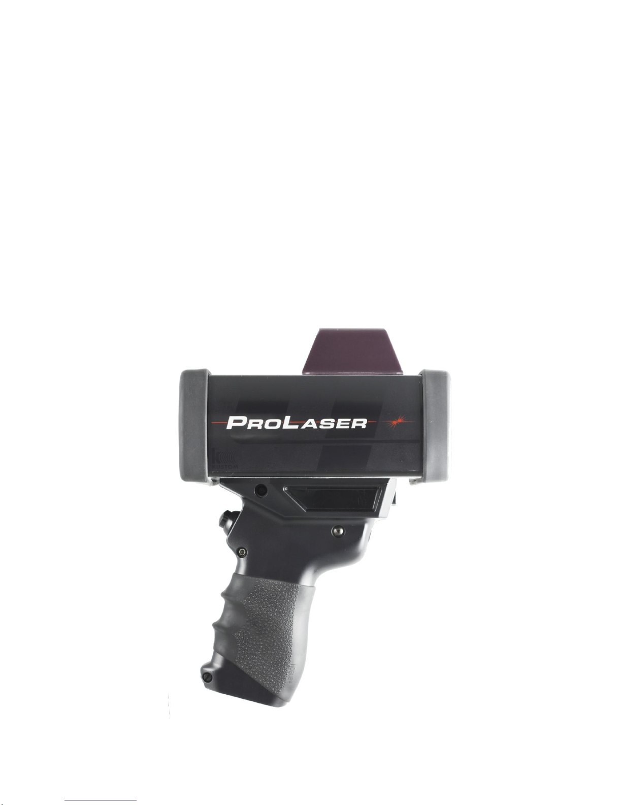
ProLaser 4
OPERATOR’S MANUAL
ProLaser 4 UK Operator’s Manual Ver 1.3 Feb16
1
Page 2

The ProLaser 4
is distributed in the UK by
Truvelo (UK) Ltd
Tel: 020 8847 4400 info@truvelouk.com www.truvelouk.com
Please contact our Service Dept for all technical queries, repairs or calibrations.
System Components
The ProLaser 4 speed detection system consists of the following components:
ProLaser 4
Carrying case
Operator’s Manual
Calibration certificate
AA batteries (4)
Options
Tripod
Shoulder stock
Neck strap
Soft bag
PLEASE NOTE
OPERATIONAL RANGE
The ProLaser 4 has a maximum range restricted to 750 metres for use in the UK.
The minimum range is 3 metres.
Speed range 0 to 200mph
When selecting a roadside location please take account of Health and Safety considerations
for operator safety.
Batteries
Your ProLaser 4 is supplied with Duracell Ultra Power AA size disposable batteries which are our
recommendation. These have been chosen after testing a number of well know brands. If however,
you prefer to use rechargeable batteries we would recommend the Ansmann Ni MH
2700mAh, AA size.
Copyright © Truvelo (UK) Ltd
All Rights Reserved. Printed in UK
This publication may not be reproduced, stored in a retrieval system, or transmitted in whole or in part in any form or by any means electronic,
mechanical, photocopying, recording, or otherwise without prior written permission of Truvelo (UK) Ltd.
ProLaser 4 UK Operator’s Manual Ver 1.3 Feb16
2
Page 3
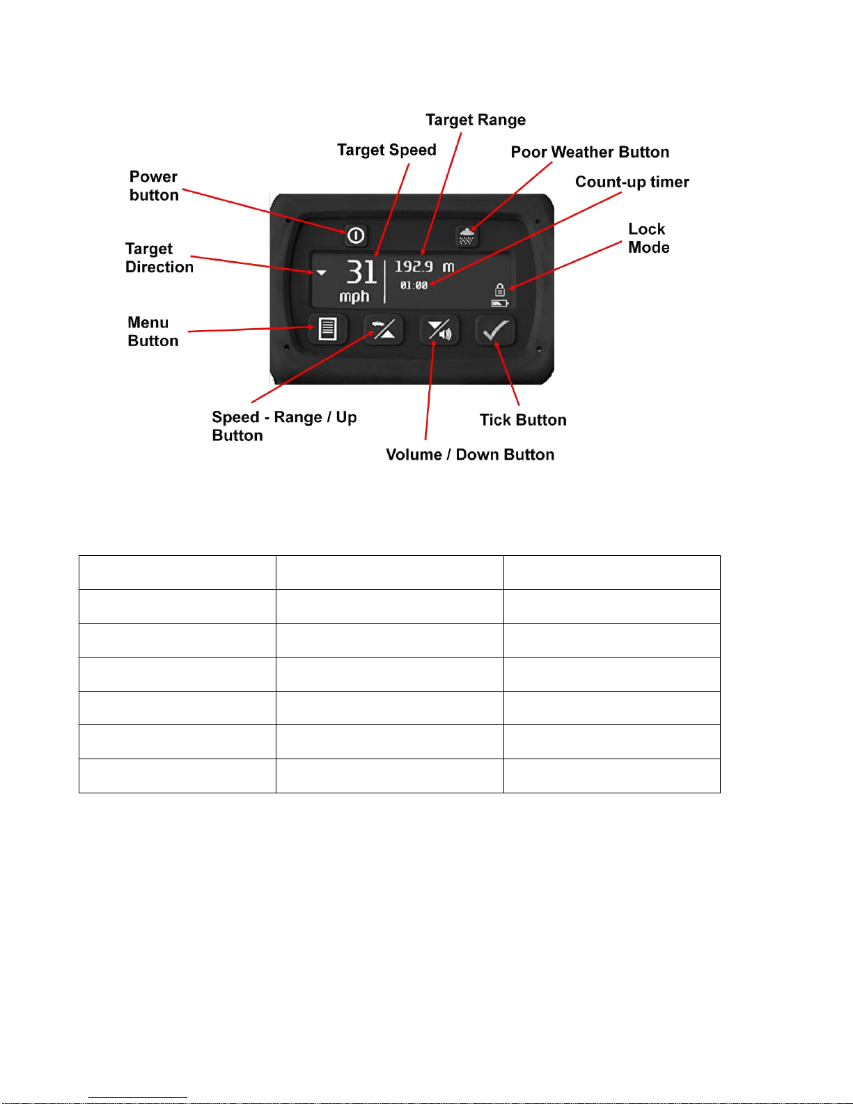
BUTTON
SINGLE PRESS
PUSH AND HOLD
Power
Rear Display Brightness
Power On / Off
Poor Weather
HUD Brightness
Poor Weather Mode
Menu
Menu
Speed – Range
Speed or Range
Up (In Menu)
Volume
Volume
Down (In Menu)
Tick
Lock Mode
Self Test
PROLASER 4 QUICK START GUIDE
ProLaser 4 Multi-function Buttons
First Time Operation
1). Press and hold Power button to turn on.
2). Hold unit by handle and aim at target using HUD.
3). Press and hold the trigger to fire the laser.
4). Position the reticle on the target and track the vehicle.
5). While holding the trigger, the speed and range continually update. A “single shot” mode will not
update as you track.
ProLaser 4 UK Operator’s Manual Ver 1.3 Feb16
3
Page 4

6). Audio tones provide targeting feedback:a).Varying tones indicate speed data has been received.
b).Solid tone indicates target acquired.
c).Intermittent regular beep – target out of range.
7). Release trigger to lock speed – this is displayed on the HUD and on the rear panel.
a). Count-up timer starts.
8). Press tick button to unlock the display. Wait 3 seconds and pull trigger again to clear the display.
9). Press tick button to lock any speed recorded. Press Tick button again to unlock.
10).Press and hold Tick Button to perform a Self Test.
ACCURACY TEST
Range and alignment tests should be carried out periodically, with a record being made that can be
recalled if required. For example in an equipment log, a witness statement or a pocket notebook.
Press the PWR switch on the back panel and allow the instrument to complete the self-test sequence.
The internal test performs a complete check of the ProLaser 4’s range and speed processing circuitry.
The following tests may then be carried out.
ALIGNMENT TEST
First check the alignment of the head-up display (HUD) aiming reticle. Select an isolated target 30
metres or more away (100ft), such as a Stop sign, utility pole or overhead power wire. Slowly sweep
the ProLaser 4 across the target and observe that the proper range is is displayed only when the target
is within the reticule area, indicating lateral alignment. Listening to the “chirp” indicating reflection of
laser pulses is helpful when using overhead wires. Rotate the ProLaser 4 so that it is at right angles to
its normal operating position (positioned on its side) and repeat the process to verify vertical alignment.
RANGE TEST
Lay out a range of known distance using one of the methods in Chapter 10 of the “ACPO Guidance for
the Operational Use of Speed and Red-Light Offence Detection Technology”. Make a measurement of
the distance between the reference mark and the target. The measurement should be taken from the
front face of the ProLaser 4. The speed should read 0 mph and the range should match the premeasured distance. Any difference should not exceed +/- 0.2 of a metre. A Range test can be carried
out in Speed mode or Range mode.
We recommend that if an operator wishes to evidence that the system confidence checks were correct
at the start and end of the enforcement, that they do that. ACPO have removed “must” from their
guidance.
SPEED ACCURACY TEST
The ProLaser 4 will measure speeds of 0mph up to 200mph. Therefore, to make a speed accuracy test
point the laser at a stationary target such as a roadsign. Pull the trigger and check that the speed
reading is 0mph.
ProLaser 4 UK Operator’s Manual Ver 1.3 Feb16
4
Page 5

Chapter 1: ProLaser 4 Description
Control Locations
Operation of the ProLaser 4 primarily involves using the rear display, the control buttons that are
located on the back panel, the Head-Up Display (HUD) on top of the unit, and the trigger that is used to
activate the unit. These controls are briefly described below
A. Organic Light Emitting Diode (OLED): A display window that shows speed, range, command
menus and unit status in a text format.
B. Power Button: A dual-function button used to turn the unit On and Off and control the rear
display brightness in Speed and Range modes.
C. Weather Button: A dual-function button used to set the unit’s Inclement Weather feature and
set HUD Brightness in Speed and Range modes.
D. Menu Button: Used to enter the Menu set-up mode and configure the unit’s 6 major functions.
In Menu mode, pressing the menu button exits and returns to Speed and Range modes.
E. Speed/Up Button: A dual-function button that sets Speed or Range mode and is used to
navigate between the Menu set-up screens in Menu mode. This button is referred to as the up button in
Menu mode.
F. Down/Volume Button: A dual-function button that sets the audio alert sound level in Speed or
Range mode and is used to navigate between the Menu set-up screens in Menu mode. This button is
referred to as the down button in Menu mode.
G. Tick Button: A multi-function button that runs the unit’s “self test” when pressed for 3 seconds
in Speed or Range mode. The tick button is also used to lock and release speed and range displays.
On the Menu set-up screens, the tick button is used to select menu options.
H. Head-Up Display (HUD): displays the aiming reticle, speed and range of a target.
I. Type A – USB Host Port: this port is for future development and is not used at this time.
Type B – USB Device Port: provides a means to physically connect the ProLaser 4 to a
Windows PC.
K Trigger: Activates the range/speed measurement function.
See Figure 1-1 on next page.
ProLaser 4 UK Operator’s Manual Ver 1.3 Feb16
5
Page 6
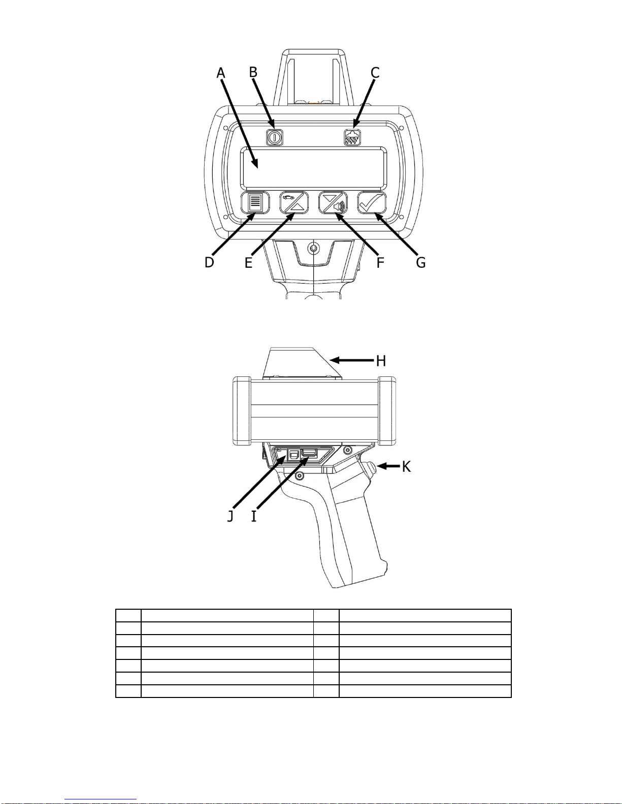
Item Description Item Description
A OLED display G Tick button
B Power button H Head-Up Display (HUD)
C Weather button I Type A - USB port (not used)
D Menu button J Type B - USB port
E Speed/up button K Trigger
F Down/volume button
Shown with USB cover
removed for clarity.
Figure 1-1. ProLaser 4 Controls
ProLaser 4 UK Operator’s Manual Ver 1.3 Feb16
6
Page 7

Chapter 2: System Operation
General Description
This chapter provides a detailed explanation of the operating characteristics of the ProLaser 4 speed
detection system.
The ProLaser 4 is a versatile instrument that measures both the range and speed of selected targets.
The advanced technology of the ProLaser 4 provides pinpoint aiming capability, permitting the user to
isolate a single vehicle out of a group. At the maximum range of 750 metres the laser beam is only
750mm wide. The technology employed in the ProLaser 4 also renders laser detection devices
relatively ineffective due to the pinpoint accuracy of the system.
The ProLaser 4 emits 200 light pulses per second. Because the wavelength of these light pulses is so
much shorter than microwaves, they can be readily focused into a narrow beam for accurate target
identification.
The technology used by the ProLaser 4 to measure distances and speeds is referred to as LIDAR,
which stands for light detection and ranging. When the trigger is pulled, the ProLaser 4 sends out two
hundred invisible infrared laser light pulses per second. As each pulse is transmitted, a timer is started,
and when the energy of a laser pulse is reflected from a target and received by the ProLaser 4, the
timer is stopped. From the elapsed time taken for the laser pulse to strike and return from the target,
the distance to the object is calculated with the known speed of light through the atmosphere. If the
target is moving with respect to the ProLaser 4, a sophisticated algorithm is used to derive the speed of
the target from a successive number of range calculations. This speed determination is then displayed
to the user.
Rear Display Control Descriptions
In Chapter 1 ProLaser 4 Description, the locations of the operating controls and displays were
introduced. (See fig 1-1). This chapter will provide detailed descriptions of each control and display.
Trigger
The trigger of the ProLaser 4 performs two functions. When the trigger is pulled, it activates the firing of
laser pulses and the range and speed measurement functions of the system. When the trigger is
released, the ProLaser 4 locks the last measured speed and range in the HUD and rear display.
Rear Display Control Buttons
The control buttons that are located adjacent to the Rear Display provide dual and multi-functionality
based on whether the unit is in Speed or Range mode or within the Menu set-up screens.
Power Button to Power On/Off
The Power Button performs two functions. It turns the unit On and Off and is used to set the brightness
of the rear display. If the ProLaser 4 is off, a single press and release of the Power Button will turn the
unit ON. Once it has powered on, press and hold the Power Button for three seconds to power the
ProLaser 4 OFF. (The ProLaser 4 will go into Sleep mode after two minutes of inactivity.)
Power Button to Control Brightness
Two separate buttons are used to adjust the brightness of the Rear Display and the Head-Up Display.
Rear Display Brightness: In Speed or Range mode, use the Power Button to set Rear Display
brightness. Five brightness settings ranging from minimum to maximum are available. Pressing the
Power Button six times cycles through all the settings (1-2-3-4-5 and back to 1). Each increment is
indicated by three lines on the display. Three lines indicate one. In the following Fig 2.1, the six lines
on the display indicate that the current setting is two.
ProLaser 4 UK Operator’s Manual Ver 1.3 Feb16
7
Page 8

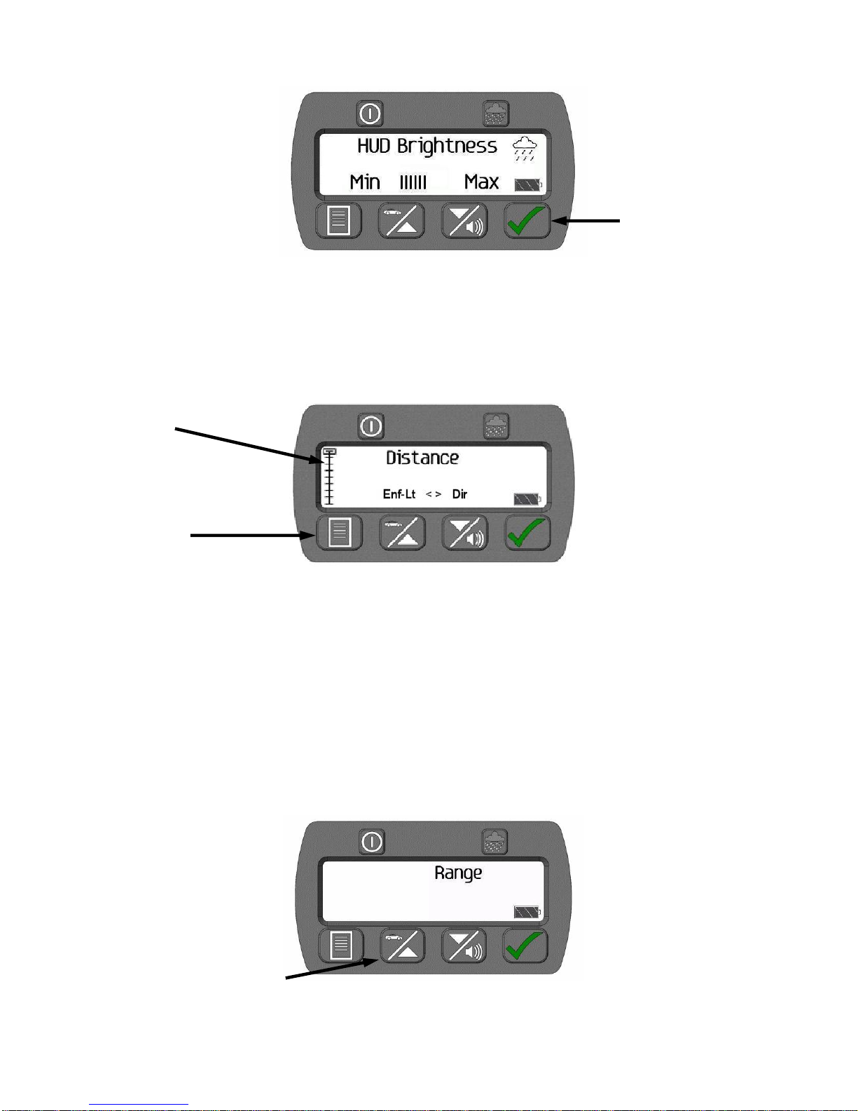
Weather button
Figure 2-1. Rear Display Brightness Screen
Weather Button
The Weather Button performs two functions. It sets the brightness of the Head-Up Display (HUD) and
turns the unit’s inclement weather feature on and off.
In either Speed or Range mode, use the Weather Button to set the brightness of the HUD, using the
HUD Brightness menu. Five brightness settings ranging from minimum to maximum are available.
Each increment is indicated by three vertical lines. In the following graphic, there are six lines,
indicating that the current setting is two. Pressing the weather button six time cycles through all the
settings (1-2-3-4-5 and back to 1).
Avoid using excessively bright settings for lower level ambient light conditions as this makes target
identification more difficult. Upon being powered up, the ProLaser 4 automatically defaults to the
brightness level set at the factory.
Figure 2-2. Weather Button Location
In Menu set-up mode, press the Weather Button once on any of the Menu screens to set the unit’s
Inclement Weather feature. The Weather icon displays on the rear display as shown above whenever
the unit is set for inclement weather. The Weather Mode prevents the ProLaser 4 operating below 60
metres and enables it to operate more efficiently in adverse weather conditions. In Speed or Range
mode press and hold the Weather Button for three seconds to set Inclement Weather mode.
Tick Button
The Tick Button is located on the back panel. This button is used to initiate three functions.
In Speed or Range mode, press and hold the Tick Button for three seconds to initiate a self-test.
Refer to Power-On Sequence for details about self-test messages.
The Tick Button is also used to activate Lock mode after taking range or speed readings. Press
the tick button once after releasing the trigger to lock the reading on the display. The Lock icon
displays when the unit is in Lock mode. To clear the locked range and speed displays in Lock
mode, momentarily press the Tick Button.
The Tick Button is also used to select menu options. Press the button when a menu or menu
option is displayed to access the selected menu, or select the displayed option.
ProLaser 4 UK Operator’s Manual Ver 1.3 Feb16
8
Page 9
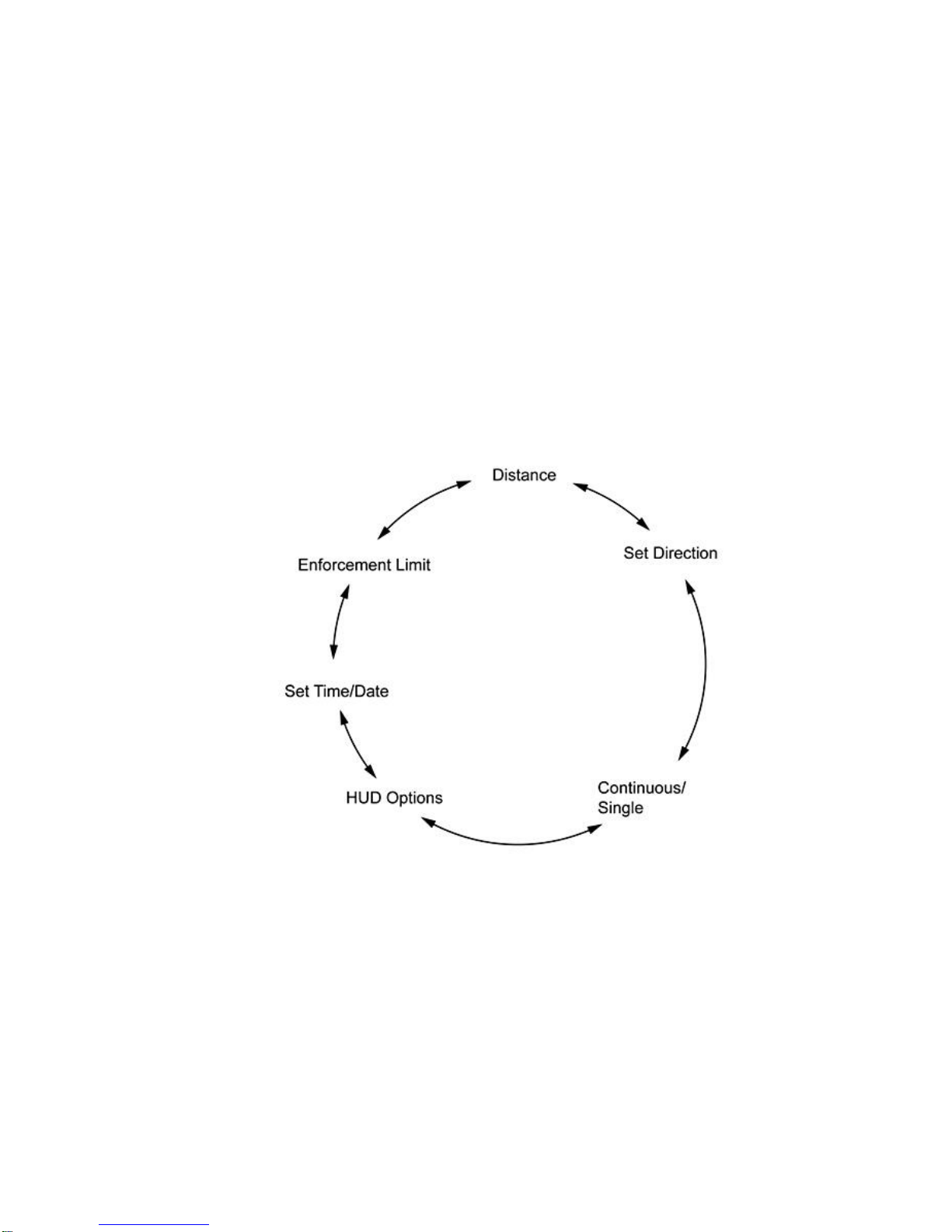
Distance
HUD options
Set Direction
Set Time/Date
Continuous/ Single
Enforcement Limit
Menu tree
Menu button
Tick Button
Speed/Up button
Figure 2-3. Tick Button Location
Menu Button
In Speed or Range mode, press the Menu button to enter the Menu set-up mode. There are six
submenus that can be accessed in Menu set-up mode. A menu tree icon displays on the left side of
the rear display to indicate where the user is within the menu screens. Text above the Up and Down
Buttons identifies the previous and next menu function.
Figure 2-4. Menu Mode – Displaying the Distance Menu Selection
The configurable menu functions are:
The ProLaser 4 menu operation is covered in detail in Chapter 3 “Using the ProLaser 4 Menu System”.
Speed/Up Button
The Speed/Up Button performs two functions. It sets the unit to either Speed or Range mode and
navigates between screens and options in the Menu mode. In Speed or Range mode, the user can
toggle between the two modes by pressing the Speed/Up Button.
Figure 2-5. Speed/Up Button – Range Mode Display
ProLaser 4 UK Operator’s Manual Ver 1.3 Feb16
9
Page 10
Down/volume button
Lines indicate setting
(three (3) lines per
increment)
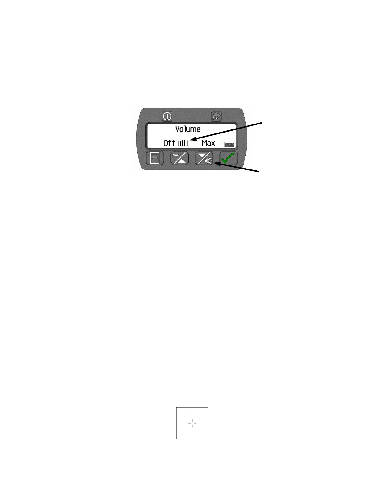
Down/Volume Button
The Down/Volume button performs two functions. The button is used to set the volume of the audio
alerts sound level when the unit is in Speed or Range mode and to navigate between options when in
Menu mode. There are five sound levels, from minimum to maximum, plus one setting with no sound
(1-2-3-4-5 and OFF). With each press of the volume button, the volume will increase one increment.
Once the volume has reached level 5, the next press of the volume button will turn the volume
completely Off. Another press of the volume button will advance to volume setting one. Each
increment is indicated by three lines on the display. Zero lines indicate OFF, three lines indicate one.
In the following figure, the six lines on the display indicate that the volume is currently set to setting two.
Figure 2-6. Volume Menu (Setting 2 Shown)
Displays and Indicators
Rear Display
The unit’s primary display is an OLED located on the back panel of the unit. The display is called the
Rear Display in the remainder of this manual. In addition to speed and range data, the Rear Display
provides set-up menus, user alerts, and self-test status. All user set-up menus and alerts are
communicated via the Rear Display in text format.
Head-up Display (HUD)
The HUD performs two critical functions in the operation of the ProLaser 4.
First, it provides the aiming reticle by which the instrument is aimed at the desired target.
Secondly, it displays the current speed and range of the target as the user continues to observe the
target, creating a tracking history.
The aiming reticle approximates to the laser beam spot size. The aiming reticle is located in the centre
of the HUD reflecting glass and defines the area where the laser beam hits the target vehicle. The
reticle is always illuminated provided the PL4 has not gone into sleep mode. The brightness can be
adjusted along with the brightness of the HUD, by using the Weather Button.
Please note: The operator can choose one of four different reticle styles, namely :dotted circle (factory default), dot (.) cross hairs (+) and X
Please note: The operator can also choose one of three different information modes in the HUD.
Speed only, Speed + Range and Range only.
Figure 2-7. Aiming Reticle (cross hairs style)
ProLaser 4 UK Operator’s Manual Ver 1.3 Feb16
10
Page 11

The batteries are full. This icon displays in the lower right
corner of the rear display.
As the battery voltage goes down, the symbol changes.
As the batteries get weaker, the symbol changes to this
icon. This indicates the batteries need to be replaced
soon. Unit is still functional.
Speed Mode: When the trigger is pulled, the HUD shows the reticle and dashes. The dashes
indicate that a speed is being acquired. Once a valid speed occurs, the dashes disappear and the
reticle and speed are displayed. The user may select the Range to be displayed as well, via the
ProLaser 4 menu system. See Chapter 3. Dashes only appear initially if the trigger is pulled.
Figure 2.8: Reticle and dashes Figure 2.8a: Speed shown (after valid acquisition)
Speed plus Range Mode:
Figure 2.9: Speed and Range in HUD
Range Mode: When the trigger is pulled, the HUD displays the reticle and dashes, then a range is
shown once a valid distance is measured. Dashes only appear initially if the trigger is pulled.
Figure 2-9. Reticle and dashes Figure 2.9a: Reticle and range
After the trigger is released, the HUD remains on for 15 seconds and then dims to save power.
Lock Mode
The ProLaser 4 flashes the Lock Mode icon on the rear display when the unit is in Lock Mode.
Pressing the Tick Button after releasing the trigger locks the current range and speed readings on the
rear display. Pressing the Tick Button a second time unlocks the unit and turns the icon off.
Figure 2-10. Lock Mode Icon
Voltage Level and Shutdown
The ProLaser 4 displays the following Battery Icons to indicate the condition of the unit’s batteries:
ProLaser 4 UK Operator’s Manual Ver 1.3 Feb16
Figure 2-11: Battery Indications
11
Page 12

The ProLaser 4 clears the rear display and displays the message “Replace Batteries” when the battery
voltage is too low to run the unit properly.
When this message is first shown, the unit sounds an audio alert for two seconds. The unit is
inoperable in this condition. This message displays for two minutes, then the unit will power down.
Figure 2-12. "Replace Batteries" Warning Message
Set-up
Two factors should be considered when setting up to use the ProLaser 4. They are (1) the location of
the instrument relative to the road, and (2) the actual setup in or around the patrol car.
In selecting a location for monitoring traffic, be aware that the ProLaser 4 is subject to the Cosine effect
in the same manner as conventional microwave radar and other laser-based speed measuring
systems. The Cosine effect is a principle which states that the apparent measured speed of a target
will be decreased from its actual speed depending upon the angle between the direction of observation
and the true direction of travel.
The amount of error is defined by a trigonometric relationship known as the cosine. From a judicial
standpoint, the measurement inaccuracy introduced by the Cosine effect is always in favour of the
motorist, since it has the effect of reducing the measured speed. The greater the angle between the
ProLaser 4 and the direction of traffic, the greater the Cosine error produced. For small angles, the
Cosine effect is relatively insignificant. For examples, at angles of less than 8°, the Cosine error is
under 1%, and at angles of less than 14°, the error is under 3%. As a general guideline, if a location is
selected where the distance to the target vehicle is at least ten times greater than the ProLaser 4's
perpendicular distance from the roadway, this corresponds to an angle of 5.7° or less, and the amount
of Cosine error will not exceed 0.5%. For example, setting up 10 meters off the roadway and
measuring targets at a range of 200 meters or greater, assures the cosine effect produces no more
than 0.5% error in the speed measurement. Again, it is important to remember that any cosine error
introduced always reduces the indicated speed reading, thus favouring the motorist.
Another factor in selecting a setup location is that a clear line of sight to the target vehicle during the
entire measurement interval is critical. Intervening objects such as signposts, utility poles, and tree
branches prevent the instrument from gathering sufficient valid measurement data to display a speedreading. It is also better to select a setup location where minimum movement of the ProLaser 4 is
required in order to keep it aimed on the desired target.
Visibility conditions also affect the performance of the ProLaser 4. Although the laser emissions used
by the device are not in the visible spectrum, they are close enough in wavelength that atmospheric or
climatic conditions that impair vision also adversely affect the operation. This impact is mitigated to
some degree due to the new “poor” weather-operating feature available on ProLaser 4. However, rain,
smoke, fog, and airborne dust particles, if sufficiently dense, may prevent its operation. The instrument
is not affected by ambient light conditions. The ProLaser 4 should meet or exceed performance
expectations whether operating in bright daylight or in total darkness.
ProLaser 4 UK Operator’s Manual Ver 1.3 Feb16
12
Page 13

The narrow beam width of the ProLaser 4 makes precise target identification possible, but it may be
difficult to aim at long ranges if operated handheld. For those situations, using a monopod, tripod, or
shoulder stock to assist in stabilising the instrument is helpful.
Power-on Sequence
Test Messages
Upon power up of the unit, or when the Tick Button is pressed and held for three seconds while in
Speed or Range Mode, the unit will run a self test. This self test consists of the following test
messages:
Programmable Options Test: Checks for corruption of the unit’s configuration memory. When the
Power Button is pressed, the first self test screen displays "Self Test" and a series of dots to indicate
activity, then displays the screen below. The dots do not display when the Tick Button is pressed to
initiate the self test. The following screen indicates a successful Programmable Options Test.
Figure 2-13. Self Test – EEPROM
Accuracy Test: Performs a comparison between two independent timing circuits to verify that
the range and speed determination circuits are operating properly.
Figure 2-14. Self Test – TIMER
Program Memory Test: Shows the unit’s firmware version and checksum.
Figure 2-15. Program Memory Test Result (Sample Shown – Your Information will vary)
ProLaser 4 UK Operator’s Manual Ver 1.3 Feb16
13
Page 14

Serial Number Screen: The unit serial number is shown immediately after the firmware version and
checksum.
Figure 2-16. Serial Number Screen
Self Test Complete: Indicates that the Self Test is complete.
Figure 2-17. Test Complete Screen
Mode/Option Selection
Speed and Range Mode
The Speed/Up button is used to toggle between Speed and Range Mode. The default mode is Speed.
Note: It is not necessary to press the Tick Button to confirm (complete mode selection).
Pressing the Speed/Up button erases the “Speed” text, leaving only the “Range” text displayed. The
unit is now in the range-only mode. This also changes the display in the HUD from Speed to Range.
This button is used to navigate between option settings as described in the “Menu Mode” section. To
return to the Speed Mode, press the Speed/Up Button again. Both Speed and Range display again on
the Rear Display, and the HUD displays speed measurements.
Audio Volume
The audible tone provides feedback to assist the user in aiming the ProLaser 4. The Aiming Tone is
activated when the trigger is pulled and a staccato or chirping tone is heard when no valid target is in
range, such as aiming the unit at the sky. As the quality of range data from a target improves, the
“chirp rate” increases, indicating proper aiming of the ProLaser 4. When a range or speed is actually
displayed, the chirping simultaneously changes to a solid tone.
The audio transducer is also used to alert the user to certain conditions such as an internal test failure,
existence of low battery voltage or confirmation the unit is powering down.
The audible alert volume is adjusted using the Volume Button in the same manner as Rear Display or
HUD brightness. Five (5) sound levels from minimum to maximum are available. Pressing the Volume
Button six times cycles through all the settings (1-2-3-4-5 and OFF). Press again to go to setting (1).
Each increment is indicated by three lines on the display. Zero lines indicate off, three lines indicate
(1). In the following figure, the six lines on the display indicate that the current setting is (2).
ProLaser 4 UK Operator’s Manual Ver 1.3 Feb16
14
Page 15

Figure 2-18. Volume Screen
Inclement Weather Feature
The Inclement Weather feature is used to improve the unit’s sensitivity and performance in adverse
weather conditions. Fog, rain, snow and heavy dust can sometimes interfere with the performance of
the ProLaser 4 or any other laser speed gun. Target ranges less than anticipated may be displayed,
typically between 15 and 60 meters. An inability for the unit to lock a valid speed is a symptom of this
problem in Speed Mode. Inclement Weather Mode improves the system performance by setting the
minimum range to 60 meters. This dramatically improves both the Speed and Range performance of
the unit in poor weather conditions. Note that no Speed or Range readings are possible inside the
minimum range while in the Inclement Weather Mode.
Figure 2-19. Inclement Weather Indication
When in the Speed or Range mode, the user can set the Inclement Weather feature by pressing and
holding the Weather Button for three seconds. Repeat this to turn this feature off.
When in any of the Menu modes shown in Figure 3-1, press the Weather Button once to set the unit’s
Inclement Weather feature. The weather icon displays on the rear display as shown above whenever
the unit is set for inclement weather.
Operating Procedures
Speed Mode
After completing the range and HUD tests, the ProLaser 4 is now ready to make range and speed
measurements.
Enforcement Limit Mode
The Enforcement Limit Mode of the ProLaser 4 is used to set a minimum enforcement speed. In other
words, the ProLaser 4 will only record the target vehicle’s speed if the speed of the vehicle is above the
Enforcement Limit setting. By default this is 20mph. Each time you restart ProLaser 4 it will revert
back to this default value. Please refer to the section "ProLaser 4 Modes of OPeration" for full details of
how to get the most out of this useful feature. If you would like Truvelo to permanently alter the default
to a higher value, such as 90mph please contact us.
ProLaser 4 UK Operator’s Manual Ver 1.3 Feb16
15
Page 16

Figure 2-20. Enforcement Limit Speed Setting
When a vehicle is targeted that is exceeding the Enforcement Limit setting, the rear display will be
locked (indicated by Lock Mode icon) and the count up timer will start. Locked speed will be added to
the internal log file.
Figure 2-21. Locked Screen After Capture
The user will not be able to take another speed reading until they unlock the rear display by pressing
the tick button. Once the display is unlocked, there will be a three second delay before the laser will be
able to fire again.
If the targeted vehicle’s speed is equal to or lower than the Enforcement Limit setting, the Rear Display
will show the range to the vehicle, as well as the speed. It will not, however, lock the display (no Lock
Mode Icon) or start the timer.
Using the ProLaser 4
The ProLaser 4 should be oriented as close to parallel to the traffic flow as the setup location will
permit. Aim the ProLaser 4 at the desired target, and pull the trigger. Four dashes "----" will
immediately be displayed in the HUD directly above the aiming reticle, indicating that the laser pulses
are being transmitted and the range and speed processing circuits are operating. If the Aiming Tone is
enabled, an intermittent tone sounds when the instrument is beginning to receive sufficient reflected
laser pulses to accurately process speed readings. When the instrument is squarely aimed at a moving
target and is processing valid speed data, the tone becomes constant. At this point the target speed
appears on the HUD in place of the dashes, and on the Rear Panel under the “Speed” text. On the
HUD, the speed indication is preceded by a "-" sign if the target is receding, and by a "+" sign if the
target is approaching. On the Rear Panel, the speed indication is preceded by an “up” arrow if the
target is receding, and by a “down” arrow if the target is approaching.
As long as the trigger is pulled, the ProLaser 4 continues to update the displayed target speed with the
most recently determined value. This procedure enables the user to correlate the displayed target
speed with visual observations of the target vehicle, thus establishing the tracking history needed for
introduction of the evidence into court. If the target aiming point is moved or lost during tracking, the
ProLaser 4 UK Operator’s Manual Ver 1.3 Feb16
16
Page 17

ProLaser 4 notifies the user by rapidly flashing the speed and range. This occurs for two seconds, and
then the display blanks, unless the aiming target is re-acquired and tracking can continue.
While the speed reading is still being displayed, releasing the trigger locks the speed and range
readings on the displays.
Range Mode
When the ProLaser 4 is first powered up, the HUD is programmed to display target speeds. For
applications in which the user is primarily interested in range information, the ProLaser 4 can be set to
display the target range in the HUD by pressing the Speed/Up button to switch to Range mode. The
Speed text disappears from the rear display and only Range displays. The ProLaser 4 is now ready to
make range measurements.
Holding the ProLaser 4 as stationary as possible, use the aiming reticle to aim the instrument at the
desired target, then pull and hold the trigger. A series of four dashes "----" will be displayed directly
above the aiming reticle while the laser is firing and range measurements are being made. After
approximately 0.3 seconds, the distance to the target appears both in the HUD and under the Range
text in the rear display. Distances are displayed to the nearest 0.1 meter in the HUD and the rear
display. Simply aim and pull the trigger again to make additional range measurements.
Since the infrared pulses used by the ProLaser 4 are close to the visible spectrum, the user will find the
target objects that best reflect light also provide maximum range from the instrument. If the user
experiences trouble getting a range reading to a certain part of a distant object, try a different, flatter
surface of the object that may have superior reflective characteristics.
If the instrument is aimed at a fairly large, distant object, and then "panned" or swept across the surface
of the structure, the intermittent aiming tone may be heard by the user. This tone occurs because the
ProLaser 4 is attempting to interpret a series of changing range measurements as a velocity. Normally,
no range reading is displayed because this erratic motion does not fulfil the accuracy criteria of the
range determination process.
Keep in mind that when making range measurements, the instrument does not measure distances
shorter than 3 metres.
ProLaser 4 External Connections
The ProLaser 4 is equipped with two USB ports, Type A and Type B. The USB ports are located on the
right side of the handle, at the top, just under the body of the ProLaser 4. The USB ports are hidden
behind a flexible rubber cover that hinges at the front. There is a tab that allows the user to easily open
the cover. When opened, the user will notice that the centre of each USB port is bright orange. This
indicates that that these are high-retention connectors. It will take more effort to connect and
disconnect a USB cable to these ports than would be required in a typical USB port.
The Type-A port is on the right and the Type-B port is on the left, closest to the display. The Type A
USB port is not used at this time. The purpose of the Type B USB port is to physically connect the
ProLaser 4 to a Windows PC.
Please note that the laser is disabled when the ProLaser 4 is connected to a PC with a USB cable.
Disconnect the USB cable before using ProLaser 4.
USB Device Port (Type B)
The Type-B USB port provides a means to connect the ProLaser 4 to a Windows PC. Please refer to
Appendix 2 for instructions on downloading the Events Log. The available customer control commands
when connected to an external computer are shown in the table below. The USB port must not be
used to connect to an external power source.
ProLaser 4 UK Operator’s Manual Ver 1.3 Feb16
17
Page 18

Command
Description
Download
Download settings.
EraseEvents
Clear all events in the event tables
Events=x
Send the latest (x) events, x=1 thru 1000
Figure 2-22. ProLaser 4 Command Structure for use with external computer
Stored Offence Data- Events Log
The ProLaser 4 captures time, date, speed and range information for each locked target. Targets
which do not lock, or which are manually locked, are not captured in the Events Log. This data is
stored in the Events Log memory and can be accessed via the USB port. 1000 records can be held in
memory. See Appendix 1 for an example.
Battery LOW
When the battery power becomes too low for operation, the "Replace Batteries" message will appear
on the rear display. Open the battery compartment door and replace the four AA batteries.
Power Conservation Features
The programming of the ProLaser 4 includes two features to help conserve power:
Sleep mode
Automatic “Power Off”
Sleep Mode
The ProLaser 4 will automatically initiate Sleep Mode if there is no activity detected for approximately
two minutes. The display blanks, and the message "Sleeping" blinks on the display. To restore the unit
to normal operation, press any of the control buttons.
A locked speed or range will return to the display when the user re-activates the unit by pressing one of
the control buttons.
Automatic Power Off
The ProLaser 4 will automatically initiate a power down if there is no activity detected for approximately
15 minutes. An audio chirp sounds to alert the user that the unit is powering down.
ProLaser 4 UK Operator’s Manual Ver 1.3 Feb16
18
Page 19
Chapter 3: Using the ProLaser 4 Menu System
General Description
This chapter provides a detailed description of the menu system of the ProLaser 4.
Menu Mode
Menu mode provides access to additional set-up and operating features of the ProLaser 4. Enter this
mode after the unit has been powered up and has completed a self test. Pressing the menu button
enables the user to refine the set-up for a particular situation.
The following is a brief description of each of the functions that may be customized using the Menu setup screens. Press the menu button to enter the Menu set-up mode. The functions are described in the
order they occur on the menu tree from top to bottom (1-6). The functions may be accessed forwards
or backwards in the sequence using the down and up buttons as shown in the following figure. After
scrolling to the bottom of the menu tree, another press of the down button will navigate back to the top
or first menu screen. From the top of the menu, a press of the Up Button will navigate to the bottom or
last menu screen.
A single press of the Menu Button will result in the following screen being displayed.
ProLaser 4 UK Operator’s Manual Ver 1.3 Feb16
Figure 3-1. Menu Layout
19
Page 20

Distance
The Distance function sets the minimum and maximum ranges at which the target vehicle
speeds are displayed.
Figure 3-2. Distance Menu
If a measurement is taken outside of this zone, no speed is displayed. Press the tick button to display
the Set Range Screen.
Figure 3-3. Set Range Screen
Use the Up or Down Buttons to toggle between the maximum (Max) and minimum (Min) range options.
Brackets and text size indicate the selected option. Press the tick button to access the Set Max Range
or Set Min Range menu screens.
Set Max Range / Set Min Range
Figure 3-4. Set Max Range Screen
Use the Up or Down buttons to change the maximum range distance setting to the desired distance.
750 metres is the default setting. The distance changes in one metre increments, but you can also
press and hold either buttton for a faster adjustment. When the desired maximum distance setting is
achieved, press the tick button to save the setting and return to the Distance menu function screen.
The Set Min Range distance is set in the same manner. The minimum range default is 3 metres.
The Min or Max Range value can be set by using the ProLaser 4 to range to a target. At the Set Max
Range display, aim the unit at a stationary target and pull the trigger until a range is displayed. The
ProLaser 4 UK Operator’s Manual Ver 1.3 Feb16
20
Page 21

range can be re-measured as many times as desired. The Up/Down Buttons can be used to adjust the
range value. When the desired value is displayed, press the Tick Button to set the maximum range.
With these settings, any target that provides an adequate signal return is displayed, up to a maximum
range of 750 metres. The distance to the target must be greater than 3 metres for the ProLaser 4 to
display a reading in either Speed or Range Mode. Each time the ProLaser 4 is powered up, the
maximum range control setting will default to its MAX setting.
Set Direction
The Set Direction menu function sets the direction of travel for target vehicles.
Figure 3-5. Set Direction Screen
Press the Tick Button to display the "Set Direction" option screen.
Direction option settings that are available are approaching ( ), receding ( ), or
both ( / ).
Figure 3-6. Set Direction Screen (Set to Approaching)
Use the Up or Down buttons to move the focus brackets to the desired option and press the Tick Button
to select the option.
Note: The both directions setting ( / ) is the default selection.
If the Approaching ( ) Mode is selected, all approaching vehicle speeds display with a plus sign (+).
However, if a receding vehicle is targeted, a dash ( - ) displays in the HUD to inform the user that the
unit is in the approaching target mode. No speed is displayed on receding vehicles.
Likewise, if Receding ( ) Mode is selected, a dash (-) displays in the HUD when an approaching
vehicle is targeted.
Note: A continuous, audible tone is still emitted when a vehicle speed is determined in a
direction that is opposite of the direction mode selected.
If both ( / ) are selected, the ProLaser 4 will display speeds for all vehicles.
ProLaser 4 UK Operator’s Manual Ver 1.3 Feb16
21
Page 22
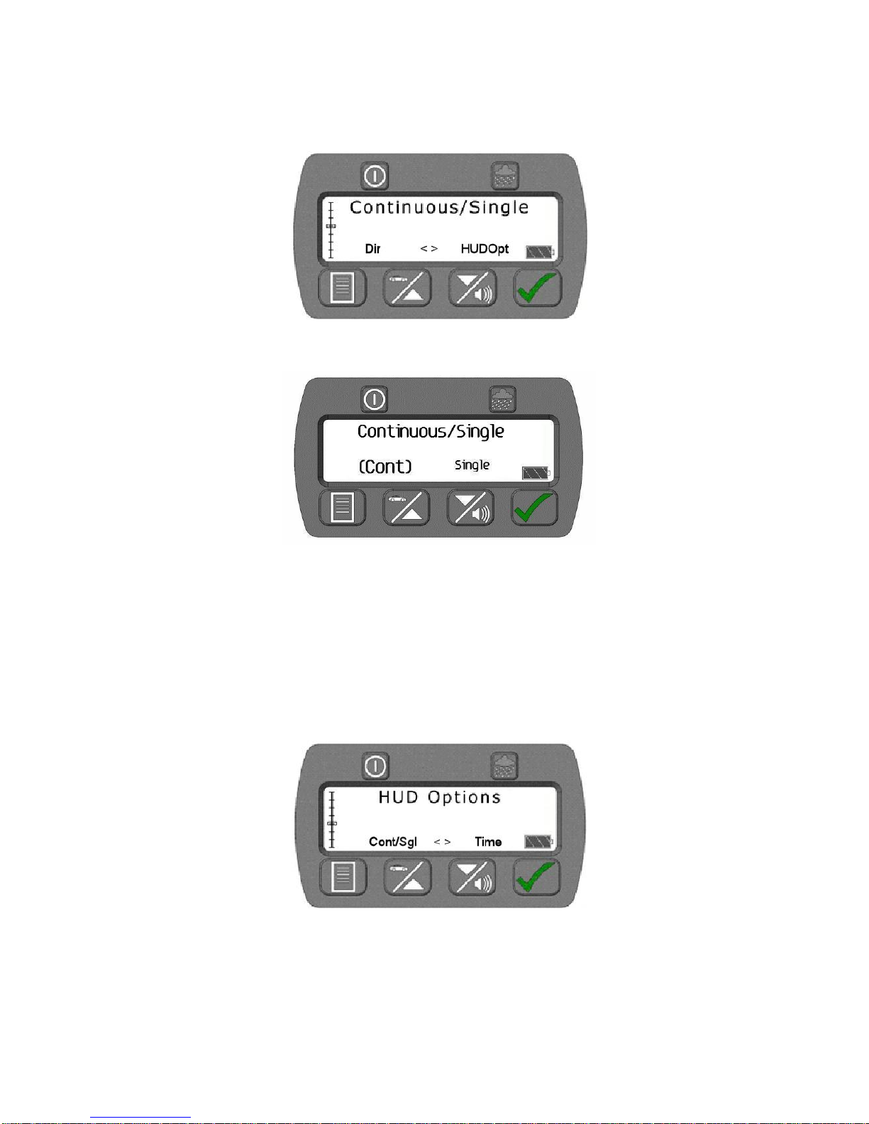
Continuous/Single
The Continuous/Single menu function sets the unit to display continuous speed updates on the screen
or show the first valid speed and stop. Press the tick button to display the Continuous/Single option
screen.
Figure 3-7. Continuous/Single Selection Screen
Figure 3-8. Continuous/Single Screen (Continuous Selected)
Use the up or down button to move the focus brackets to the desired option and press the tick button to
select the option.
Count-Up Timer
A minutes/seconds count-up timer appears under the range measurement to show the elapsed time
since the last locked speed infringement. In “single shot” mode it starts after a speed is locked, and in
“continuous mode” it starts when the trigger is released and a speed locked.
HUD Options
Figure 3-9. HUD Options Selection
Press the Tick Button to access the HUD Options screen. The HUD Options menu is used to turn the
range data display in the HUD On or Off, and to set the type of reticle that will be used. The default
setting is On. Press the tick button to access the HUD Options screen.
ProLaser 4 UK Operator’s Manual Ver 1.3 Feb16
22
Page 23
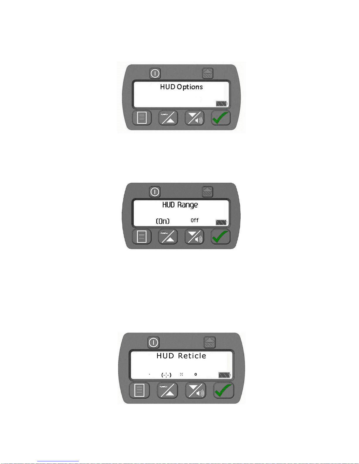
(Range)
Reticle
On the HUD Options menu, the user is presented with two choices. They will select Range to access
the HUD Range submenu or they can select Reticle to access the HUD Reticle submenu. In the
following figure, Range is selected, which is indicated by its larger text and focus brackets around the
word Range. Press the tick button to access the Range menus.
Figure 3-10. HUD Options Range/Reticle Selection Screen (Range Selected)
HUD Range
From the HUD Range screen, the user can turn the HUD Range on or off.
Figure 3-11. HUD Range Screen (On Selected)
Use the Up or Down button to move the focus brackets to the desired option and press the Tick Button
to select the option.
HUD Reticle
From the HUD Options menu, the user will access the Reticle settings. The user will press the down
arrow button to move the focus brackets to the desired option and press the Tick Button. The following
screen will appear. The operator must use the Up or Down Button to move the focus brackets to the
desired reticle selection, and press the Tick Button to select that reticle for use.
Figure 3-12. HUD Reticle Screen
ProLaser 4 UK Operator’s Manual Ver 1.3 Feb16
23
Page 24
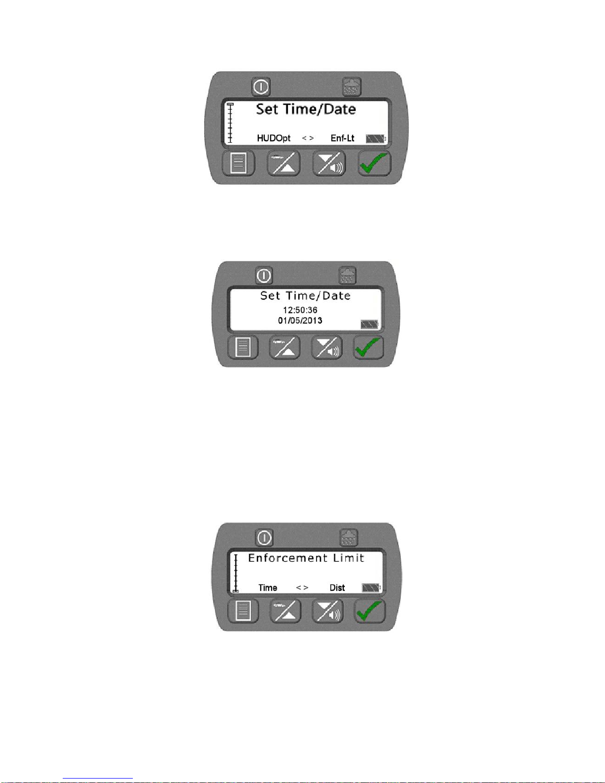
Set Time/Date
Figure 3-14. Set Time/Date Selection Screen
The Set Time/Date menu function is used to set the unit to the current time and date. This is only used
when saving locked speeds in the log file.Press the Tick Button to display the Set Time/Date options
screen.
Figure 3-15. Set Time/Date Screen
Use the Tick Button to move the focus between the hour, minutes, seconds, year, month, and day
positions and then use the Up or Down Button to select the desired setting for each.
Note: Press and hold the Tick Button for two seconds to save the new time and date.
Enforcement Limit Menu
The Enforcement Limit feature on the ProLaser 4 allows the user to set a minimum speed setting for
enforcement. This feature prevents capturing vehicle speed data from vehicles that are travelling at or
below the minimum speed setting. The Enforcement Limit menu is the last item in the menu tree.
Figure 3-16. Enforcement Limit Menu Selection
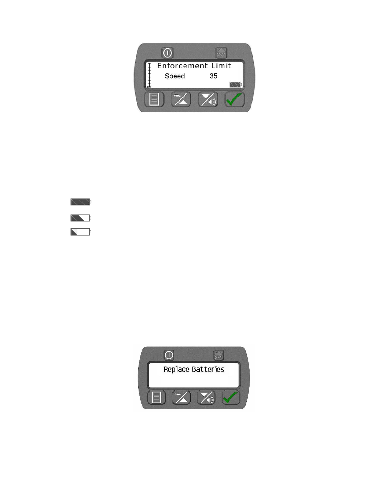
Once the user has navigated to the Enforcement Limit menu selection, the user will press the Tick
Button to access the Enforcement Limit menu. When the menu opens, the current speed setting will be
displayed. The user can increase the speed setting by pressing the Up Button, and can decrease the
speed setting by pressing the Down Button. A single press and release of the Up/Down button will
increase/decrease the setting by one. By pressing and holding the Up or Down button, the speed
ProLaser 4 UK Operator’s Manual Ver 1.3 Feb16
24
Page 25
The batteries are full. This icon displays in the lower right corner of the
rear display.
As the battery voltage goes down, the symbol changes to this icon.
As the batteries get weaker (but still able to power the unit) the symbol
changes to this icon. This indicates the batteries need to be replaced
soon, but the unit is still functional.
setting will increase/decrease in increments of five. Once the desired setting is achieved, press the
Tick Button to save.
Figure 3-17. Enforcement Limit Speed Setting
BATTERIES
Voltage Level and Shutdown
The ProLaser 4 displays the following battery icons and warning to indicate the condition of the unit’s
internal batteries:
Figure 3.18 Battery Indications
The ProLaser 4 clears the Rear Display and shows the following message (see Fig 3.19) when the
battery voltage is too low.
When this message is first shown, the unit sounds an audio alert for two seconds. The unit is
inoperable in this condition. This message displays for two minutes, then the unit will power down.
The ProLaser 4 uses four AA alkaline batteries. The user will be notified of the need to replace the
batteries via a warning message on the Rear Display.
Figure 3.19 "Replace Batteries" Warning Message
ProLaser 4 UK Operator’s Manual Ver 1.3 Feb16
25
Page 26

Operating temperature range
- 30 ºC to 60 ºC
Storage temperature range
- 40 ºC to 80 °C
Relative humidity (electronics)
0 - 95% non-condensing
Chapter 4: Regulatory Compliance
General Description
The ProLaser 4 is a Home Office approved device and therefore meets all the necessary
environmental and safety standards. This includes Class 1 eye safety.
However, sensible precautions should still be taken. A person should not stare directly
into the laser beam.
Temperature range
The ProLaser 4 exceeds Home Office requirements for temperature. The manufacturer’s spec is
shown below.
Figure 4-1. Environmental Requirements
Airwave (TETRA) Radios: Transmit inhibit is not mandatory for Home Office Type Approved
devices under the current ACPO guidance. However, the guidance does state that calls
should not be made at the same time as operating such a device. We recommend that you
consult the latest edition of the ACPO guidelines for full details.
ProLaser 4 UK Operator’s Manual Ver 1.3 Feb16
26
Page 27

Appendix 1: ProLaser 4 Events Log example
12/06/2013, 11:14:22, +048,mph, rng,0364,m, min,0003,m, max,0750,m, track,0.3s
12/06/2013, 11:14:12, +050,mph, rng,0593,m, min,0003,m, max,0750,m, track,0.3s
12/06/2013, 11:13:21, -050,mph, rng,0726,m, min,0003,m, max,0750,m, track,0.3s
12/06/2013, 11:13:16, -049,mph, rng,0610,m, min,0003,m, max,0750,m, track,0.3s
12/06/2013, 11:13:10 ,-049,mph, rng,0477,m, min,0003,m, max,0750,m, track,0.3s
12/06/2013, 11:13:05, -050,mph, rng,0370,m, min,0003,m, max,0750,m, track,0.3s
The above data represents a download/printout of 6 speed readings from the Events Log. A total of
1000 events can be stored. If not cleared then new data will automatically overwrite the oldest data.
The information provided is as follows:-
Date, Hrs, mins, secs, direction & speed, Range (rng) to target vehicle, min range (3 m), max range 750 (m),
Target tracked after acquisition, Acquisition time(secs)
A + sign before the speed means an approaching vehicle.
A – sign before the speed means the vehicle is departing.
See Appendix 2 for download instructions using Hyperterminal
ProLaser 4 UK Operator’s Manual Ver 1.3 Feb16
27
Page 28

Appendix 2: Download Events Log using Hyperterminal
The ProLaser 4 captures time, date, speed and range information when the trigger is released after
each “firing” at a target vehicle. NB: The data is only written to memory if the target is locked.
This data is stored in memory and can be accessed via the square ‘Type B’ USB port. (see p4 and 15).
1,000 records can be held in memory. Data will be progressively overwritten when over 1,000 targets
have been locked. It is therefore advisable to download such data frequently to preserve it for your
records.
To download the stored data we can use a piece of software such as Microsoft Hyperterminal.
Hyperterminal was distributed with versions of Windows up to and including Windows XP. If you are
using Windows Vista or later you will need to download and install Hyperterminal from a Microsoft
support site or ask your IT administrator. In order to run Hyperterminal you will need a copy of both
Hyperterminal.exe and Hyperterminal.dll.
Connecting your ProLaser 4 to your PC
In order for your PC to communicate with your ProLaser 4, you will need to install USB drivers onto
your PC. These drivers are available from Truvelo. The first time you connect a ProLaser 4 to your PC
you will have to follow the installation procedure:
1) Copy the directory containing the supplied drivers to the target PC.
2) Connect the ProLaser 4 to the PC using a USB cable.
3) Windows will find an unknown USB device.
4) Windows will recommend that you allow it to search for the drivers, but you need to reject this
and ask to find them yourself.
5) Point windows manually to the directory where you copied the drivers to your PC as per stage 1.
Running Hyperterminal
1) Connect the ProLaser 4 to your PC and then double-click the hyperterminal.exe icon to run the
program.
2) You will be asked to create a new connection.
3) Select a name for this such as “ProLaser4” and then select OK to proceed.
4) Hyperterminal will automatically select the USB port to which your ProLaser 4 is already
connected. Click OK to accept this dialogue and then do the same again for the subsequent
dialogue and you will be connected.
5) A count-up timer will start in the bottom corner of Hyperterminal to indicate a successful
connection.
6) At the end of the session you will be able to save the connection details for ease of use in the
future, but you need to remember which USB port you connected to on your PC.
Hyperterminal input and output
Hyperterminal has a very simplistic interface, and it is not immediately obvious that it is working
correctly.
Data input and output is through the same main window in hyperterminal.
When you select and type into the main window, the text that you type is not actually displayed! Do not
be deterred.
The table below shows the commands that you can type into Hyperterminal:
ProLaser 4 UK Operator’s Manual Ver 1.3 Feb16
28
Page 29

Command
Description
download
Download settings
eraseevents
Deletes all events currently stored in the on-board memory
events=x
Download the latest (x) events, where x = a number between 1
and 1000. No data is deleted when using this function.
For example, to download the datalog stored in memory, simply type the following command followed
by the return key:
Events=1000
You will see something similar to the following appear in Hyperterminal:
07/06/2013,16:27:21,-077,mph,rng,0607,m,min,0003,m,max,0750,m,track,2.7s
07/06/2013,16:25:40,+072,mph,rng,0556,m,min,0003,m,max,0750,m,track,0.8s
07/06/2013,16:25:28,+071,mph,rng,0488,m,min,0003,m,max,0750,m,track,0.5s
07/06/2013,16:25:09,+068,mph,rng,0471,m,min,0003,m,max,0750,m,track,0.6s
07/06/2013,16:21:23,+056,mph,rng,0675,m,min,0003,m,max,0750,m,track,0.7s
07/06/2013,16:20:37,+061,mph,rng,0492,m,min,0003,m,max,0750,m,track,9.5s
07/06/2013,16:19:38,+053,mph,rng,0620,m,min,0003,m,max,0750,m,track,2.2s
07/06/2013,16:19:17,-068,mph,rng,0327,m,min,0003,m,max,0750,m,track,7.0s
07/06/2013,16:18:12,-056,mph,rng,0243,m,min,0003,m,max,0750,m,track,2.6s
07/06/2013,16:17:19,-045,mph,rng,0738,m,min,0003,m,max,0750,m,track,4.8s
End of Event List
At this point you can right-click in the Hyperterminal window and click “select all” followed by “Copy” to
copy the contents to your windows clipboard.
Once the data is in your Windows clipboard you can paste it into the application of your choice.
If you wish to convert it into a spreadsheet, paste it into field A1 of a new Excel workbook and then you
can convert the data to columns easily using the “Text to columns” command. You have to tell Excel
that the data is coma separated.
If you wish to delete all records from the memory, you need to use the command eraseevents.
At the end of your Hyperterminal session, disconnect properly by clicking the “disconnect” icon. When
the count-up timer disappears to be replaced by “disconnected” - it is safe to unplug your ProLaser 4
from your PC.
ProLaser 4 UK Operator’s Manual Ver 1.3 Feb16
29
Page 30

Continuous Mode
Single Mode
< Threshold
Range and Speed are
continuously updated. As
soon as you release the
trigger the last displayed
speed and range are held
in the display although
they will not be locked.
This is just the same as
ProLaser III behaviour.
As soon as a moving
target is acquired the
Range and Speed are
instantly held. The
display will cease to
update even if you
continue to hold the
trigger. Releasing and
then pulling the trigger
again allows the cycle to
repeat. At no point will the
speed and range be
locked.
> Threshold
Range and Speed are
continuously updated until
you release the trigger.
As soon as you release
the trigger, the last
displayed speed and
range will be locked,
assuming the speed still
exceeds the threshold.
As soon as a moving
target is acquired, the
Range and Speed are
instantly locked. The
display will cease to
update even if you
continue to hold the
trigger.
Appendix 3: ProLaser 4 Modes of Operation
When tracking vehicles by pulling and holding the trigger continuously, we see the following
behaviour.
Notes:
A locked speed will not be cleared with a repeat trigger pull. The operator has to press
the tick button and then wait 3 seconds to unlock a locked speed. Then it reverts to a
held speed.
A held speed will be retained in the display, but it will be cleared by a repeat trigger pull.
This is exactly what you would get with the ProLaser III.
It is possible to lock a held speed by pressing the tick button.
ProLaser 4 UK Operator’s Manual Ver 1.3 Feb16
30
Page 31

Index
Accuracy Test ................................... 4 & 13
Alignment test ............................................ 4
Audio Volume ........................................... 14
Automatic Power Off ................................ 18
Batteries ................................................... 25
Tick Button ................................................. 8
Continuous/Single .................................... 22
Control Descriptions ................................... 7
Control Locations ....................................... 5
Count-Up timer ......................................... 22
Distance ................................................... 20
Down/Volume Button ............................... 10
Enforcement Limit menu .......................... 24
Enforcement Limit Mode .......................... 15
Events Log ............................................... 18
Eye safety ................................................ 26
Head-Up Display (HUD) ........................... 10
HUD options ............................................. 22
HUD Range .............................................. 23
HUD Reticle ............................................. 23
Inclement Weather Feature ...................... 15
Lock Mode ............................................... 11
Menu Button ............................................... 9
Menu Mode .............................................. 19
Menu System explained ........................... 19
Mode/Option Selection ............................. 14
Operational range ...................................... 2
Operating Procedures .............................. 15
Power Button ...................................... 3 & 5
Power Button to Control Brightness ........... 7
Power Conservation Features .................. 18
Power-on Sequence ................................ 13
ProLaser 4 Description............................... 5
ProLaser 4 External Connections ............ 17
Quick Start guide ....................................... 3
Range Mode ............................................ 17
Range test .................................................. 4
Rear Display brightness ............................. 7
Rear Display ....................................... 6 & 8
Rear Display Control Buttons ..................... 6
Regulatory Compliance ............................ 26
Replace batteries warning ........................ 25
Reticle selection .............................. 10 & 23
Self Test ................................................... 14
Serial Number Screen .............................. 14
Set Direction ............................................ 21
Set Max Range / Set Min Range .............. 20
Set Time/Date ......................................... 24
Set-up ...................................................... 12
Sleep Mode ............................................. 18
Speed and Range Mode ......................... 14
Speed Mode ............................................ 11
Speed/Up Button ....................................... 9
System Operation...................................... 7
Test Messages ........................................ 13
Tick Button ................................................ 8
USB Device Port ..................................... 17
Using the ProLaser 4 Menu System ........ 19
Voltage Alert and Warning ...................... 11
Voltage Level and Shutdown ........... 11 & 25
Weather Button ......................................... 8
Appendix 1 Event Log 27
Appendix 2 Hyperterminal instructions 28
Appendix 3 ProLaser 4 Modes of Operation 30
ProLaser 4 UK Operator’s Manual Ver 1.3 Feb16
31
Page 32

ProLaser 4 UK Operator’s Manual Ver 1.3 Feb16
32
 Loading...