

Page 1
08-09-1371
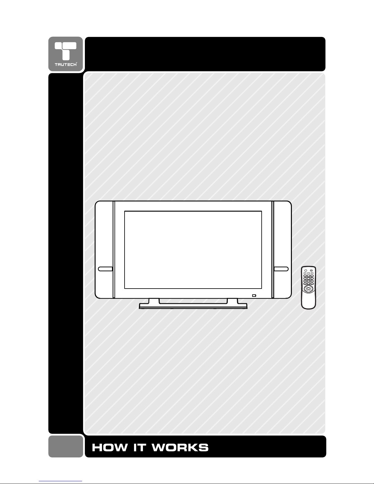
32" THIN LCD MONITOR
WIDESCREEN
Page 2
2
SAFETY PRECAUTIONSSAFETY PRECAUTIONS
SAFETY PRECAUTIONSSAFETY PRECAUTIONS
SAFETY PRECAUTIONS
* SEE REAR OF UNIT FOR GRAPHIC SYMBOLS ** SEE REAR OF UNIT FOR GRAPHIC SYMBOLS *
* SEE REAR OF UNIT FOR GRAPHIC SYMBOLS ** SEE REAR OF UNIT FOR GRAPHIC SYMBOLS *
* SEE REAR OF UNIT FOR GRAPHIC SYMBOLS *
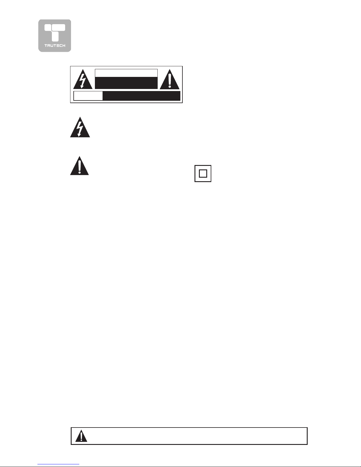
The exclamation point within a
triangle alerts you to the
presence of important
operating, maintenance and
servicing instructions in this user’s
manual.
The lightning flash with an
arrowhead within a triangle
alerts you to uninsulated
dangerous voltage within the
product's enclosure that could cause an
electric shock.
WARNING: TO REDUCE THE RISK OF
ELECTRIC SHOCK, DO NOT REMOVE
COVER (OR BACK). NO USERSERVICEABLE PARTS INSIDE. REFER
SERVICING TO QUALIFIED PERSONNEL.
WARNING: TO PREVENT FIRE OR SHOCK
HAZARD, DO NOT EXPOSE THIS UNIT TO
RAIN OR MOISTURE. DO NOT PLACE
OBJECTS FILLED WITH LIQUIDS ON OR
NEAR THIS UNIT.
CAUTION: DANGER OF EXPLOSION IF
BATTERY IS INCORRECTLY REPLACED.
REPLACE ONLY WITH THE SAME OR
EQUIVALENT TYPE.
PLACEMENT INFORMAPLACEMENT INFORMA
PLACEMENT INFORMAPLACEMENT INFORMA
PLACEMENT INFORMA
TIONTION
TIONTION
TION
• Do not use this unit in places which are extremely hot, cold, dusty, or humid.
• Do not restrict the air flow of this unit by placing it somewhere with poor air flow, by
covering it with a cloth, or by placing it on bedding or carpeting.
SAFETY INFORMASAFETY INFORMA
SAFETY INFORMASAFETY INFORMA
SAFETY INFORMA
TIONTION
TIONTION
TION
• When connecting or disconnecting the AC cord, grip the plug and not the cord itself.
Pulling the cord may damage it and create a hazard.
• When you are not going to use the unit for a long period of time, disconnect the AC
cord.
CONDENSACONDENSA
CONDENSACONDENSA
CONDENSA
TION INFORMATION INFORMA
TION INFORMATION INFORMA
TION INFORMA
TIONTION
TIONTION
TION
• When left in a heated room where it is warm and damp, water droplets or condensation
may form inside the unit. When there is condensation inside the unit, the unit may not
function normally. Let the unit stand for 1-2 hours before turning the power on, or
gradually heat the room and let the unit dry before use.
FCC INFORMAFCC INFORMA
FCC INFORMAFCC INFORMA
FCC INFORMA
TIONTION
TIONTION
TION
WARNING:WARNING:
WARNING:WARNING:
WARNING: Changes or modifications to this unit not expressly approved by the party
responsible for compliance could avoid the user authority to operate the equipment.
NOTE:NOTE:
NOTE:NOTE:
NOTE: This equipment has been tested and found to comply with the limits for a Class B
digital device, pursuant to part 15 of the FCC Rules. These limits are designed to provide
reasonable protection against harmful interference in a residential installation. This
equipment generates, used in accordance with the instructions, may cause harmful
interference to radio communications. However, there is no guarantee that interference
will not occur in a particular installation. If this equipment does cause harmful interference
to radio or television reception, which can be determined by turning the equipment does
cause harmful interference to radio or television reception, which can be determined by
turning the equipment off and on, the user is encouraged to try to correct the interference
by one or more of the following measures:
• Reorient or relocate the receiving antenna.
• Increase the separation between the equipment and receiver.
• Connect the equipment into an outlet on a circuit different from that to which the receiver
is connected.
• Consult the dealer or an experienced radio/TV technician for help.
Shielded cables must be used with this unit to ensure compliance with the Class FCC limits.
The symbol for Class II
(Double lnsulation)
AVIS
RISQUE DE CHOC ÉLECTRIQUE NE
PAS OUVRIR
CAUTION
RISK OF ELECTRIC SHOCK
DO NOT OPEN
WW
WW
W
ARNING:ARNING:
ARNING:ARNING:
ARNING: Should any problems occur, disconnect the AC cord and refer
servicing to a qualified technician.
Page 3
3
IMPORTANT SAFETY INSTRUCTIONS
1. Read these instructions.
2. Keep these instructions.
3. Heed all warnings.
4. Follow all instructions.
5. Do not use this apparatus near
water.
6. Clean only with dry cloth.
7. Do not block any ventilation
openings. Install in accordance
with the manufacturer’s
instructions.
8. Do not install near any heat sources
such as radiators, heat registers,
stoves, or other apparatus
(including amplifiers) that product
heat.
9. Do not defeat the safety purpose
of the polarized or grounding-type
plug. A polarized plug has two blades
with one wider than the other. A
grounding type plug has two blades
and a third grounding prong. The
wide blade or the third prong are
provided for your safety. If the
provided plug does not fit into your
outlet, consult an electrician for
replacement of the obsolete outlet.
10. Protect the power cord from being
walked on or pinched particularly at
plugs, convenience receptacles, and
the point where they exit from the
apparatus.
11. Only use attachments/accessories
specified by the manufacture.
12. Use only with the cart,
stand, tripod, bracket,
or table specified by the
manufacturer, or sold
with the apparatus.
When a cart is used, use caution
when moving the cart/apparatus
combination to avoid injury from tipover.
13. Unplug this apparatus during
lightning storms or when unused for
long periods of time.
14. Refer all servicing to qualified service
personnel. Servicing is required when
the apparatus has been damaged in
any way, such as power-supply cord
or plug is damaged, liquid has been
spilled or objects have fallen into the
apparatus, the apparatus has been
exposed to rain or moisture, does
not operate normally, or has been
dropped.
SAFELSAFEL
SAFELSAFEL
SAFEL
Y REMOVING THE UNIT FROM THE BOXY REMOVING THE UNIT FROM THE BOX
Y REMOVING THE UNIT FROM THE BOXY REMOVING THE UNIT FROM THE BOX
Y REMOVING THE UNIT FROM THE BOX
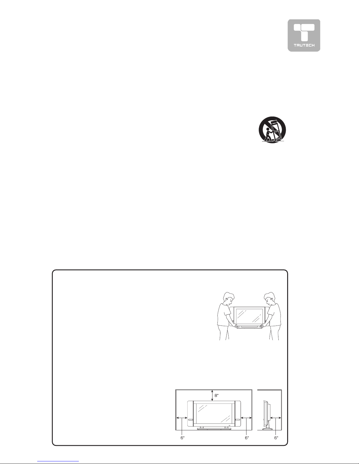
For your safety, and to protect the fragile LCD screen, it’s best to use 2
people to remove the unit from the box.
1. Use the cardboard holders on either side of the
unit to remove it from the box.
2. Remove the cardboard; however, keep the
wrapping on the unit to protect it while moving.
3. Gently place the unit in its desired location,
making sure there is ample space on all sides,
as shown in the attached diagram.
PRECAUTION WHEN MOVING THE UNITPRECAUTION WHEN MOVING THE UNIT
PRECAUTION WHEN MOVING THE UNITPRECAUTION WHEN MOVING THE UNIT
PRECAUTION WHEN MOVING THE UNIT
When transporting the unit, never carry it by holding onto the speakers. Be
sure to always move the television with two people, supporting it with two
hands, one on each side of the display.
SPACE REQUIREMENTSSPACE REQUIREMENTS
SPACE REQUIREMENTSSPACE REQUIREMENTS
SPACE REQUIREMENTS
For proper ventilation of the unit,
and to avoid overheating, ensure the
unit has 6” of space on either side,
8” on the top, and 6” behind, as
shown in the diagram.
Page 4

4
TABLE OF CONTENTS
SAFETY PRECAUTIONS ................................................. 2
IMPORTANT SAFETY INSTRUCTIONS ............................... 3
REMOTE CONTROL ...................................................... 5
ACCESSORIES ............................................................ 5
REMOTE CONTROL REFERENCE GUIDE ........................... 6
UNIT REFERENCE GUIDE .......................................... 7-8
CONNECTIONS ....................................................... 9-13
Connecting to A/V devices (VCR, Camcorder, Game
System, etc.) ................................................... 9-10
Connecting to sources with component video output (DVD
- only 480i, 480p, 720p & 1080i are supported)
.......................................................................... 11
Connecting an audio amplifier ............................... 12
Connecting a PC .................................................. 12
Connecting the power cord ................................... 13
INSTALLATION ............................................................ 14
Removing the base stand ...................................... 14
Mounting on the wall ........................................... 14
USING HEADPHONES ................................................... 15
MENU SETUP ....................................................... 16-21
Picture menu ....................................................... 16
Screen menu ....................................................... 17
Sound menu ....................................................... 18
Setup menu ......................................................... 19
Restore setting ............................................... 19
Timers setting ................................................ 19
Parental control ............................................ 20
Closed-captioning ........................................... 21
Noise reduction ............................................... 21
On-Screen display setting ...................................... 22
TROUBLESHOOTING GUIDE ............................................ 23
Page 5
5
REMOTE CONTROL
USING THE REMOTE CONTROLUSING THE REMOTE CONTROL
USING THE REMOTE CONTROLUSING THE REMOTE CONTROL
USING THE REMOTE CONTROL
• Point the remote control at the REMOTE SENSOR located on the unit.
• When using this unit in very bright light, the infrared REMOTE CONTROL
SENSOR may not work properly.
• The recommended effective distance for using the remote control is about
16 feet (5 meters).
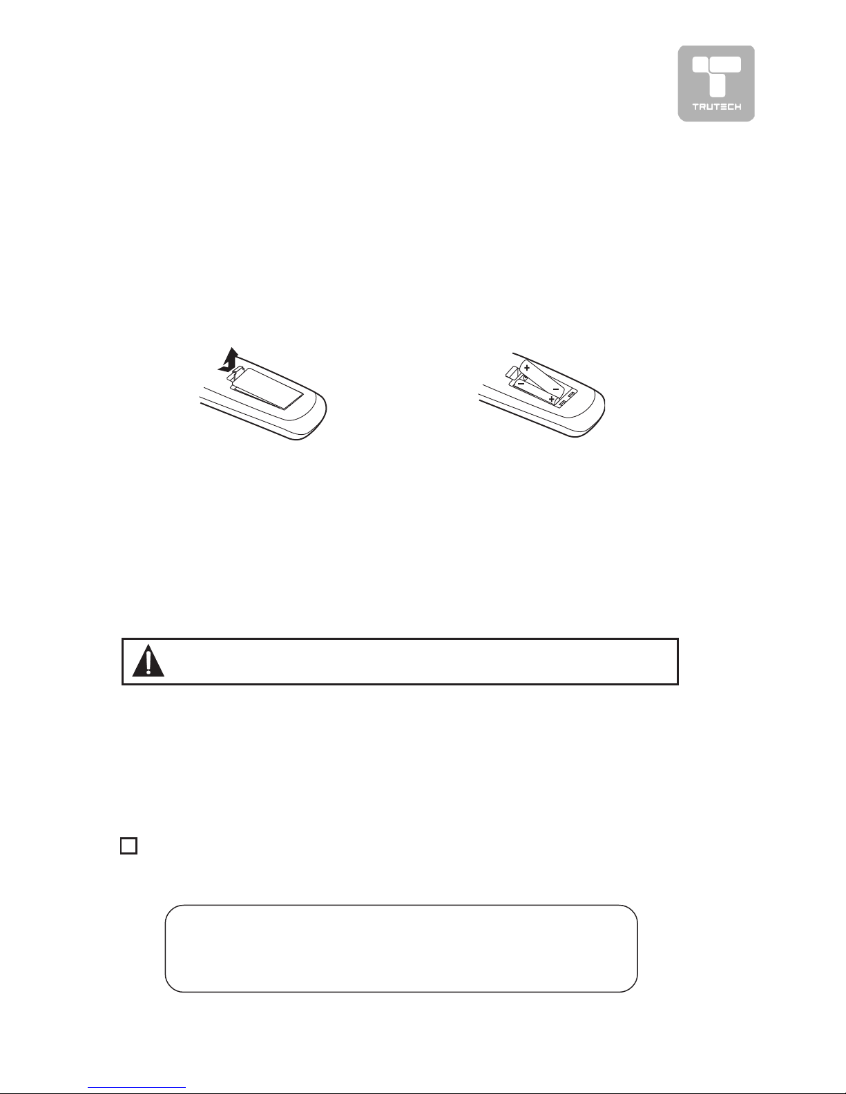
TO CHANGE THE REMOTE CONTROL BATO CHANGE THE REMOTE CONTROL BA
TO CHANGE THE REMOTE CONTROL BATO CHANGE THE REMOTE CONTROL BA
TO CHANGE THE REMOTE CONTROL BA
TTERTTER
TTERTTER
TTER
YY
YY
Y
1. Open the battery door. 2. Insert two “AAA” batteries.
ACCESSORIES
PLEASE LOCATE THE INCLUDED ACCESSORIES.
• To order replacement parts, please call customer service at 1-888-252-6252
or visit http://www.1800customersupport.com.
Remote control (with battery) ......................................................... x 1
Need More Help?
DO NOT RETURN THIS TO THE STORE
Please call Customer Service at 1-888-252-6252or
visit online help at http://www.1800customersupport.com
Specifications and appearance are subject to change without notice.
BATTERY REPLACEMENTBATTERY REPLACEMENT
BATTERY REPLACEMENTBATTERY REPLACEMENT
BATTERY REPLACEMENT
When the batteries become weak, the operating distance of the remote control
will be greatly reduced and you will need to replace the batteries.
Note:
• If the Remote Control is not going to be used for a long time, remove the
batteries to avoid damage caused by battery leakage corrosion.
• Do not mix old and new batteries. Do not mix ALKALINE, standard (CARBONZINC) or rechargeable (NICKEL-CADMIUM) batteries.
WARNING: Do not dispose of batteries in a fire or they may leak and/
or explode.
Page 6
6
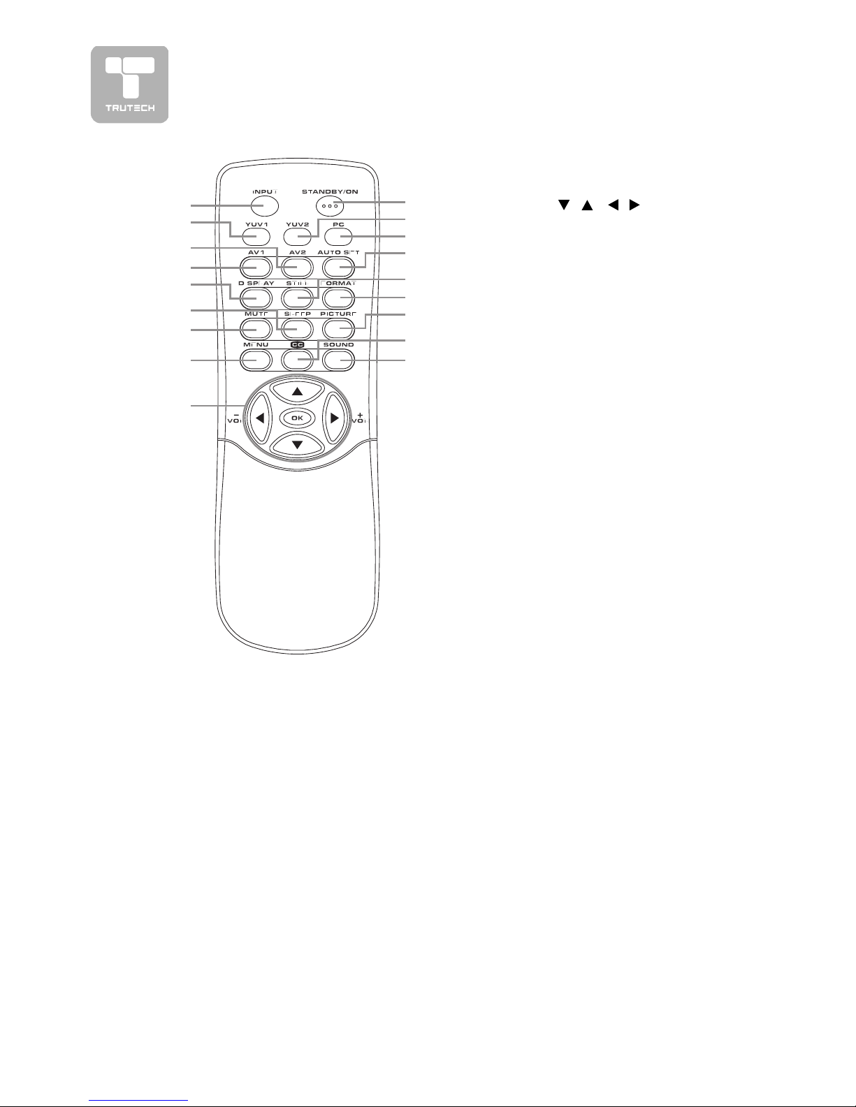
REMOTE CONTROL REFERENCE GUIDE
1)1)
1)1)
1)
INPUTINPUT
INPUTINPUT
INPUT
button button
button button
button
Toggle between AV1/AV2/
YUV1/YUV2/PC IN.
2)2)
2)2)
2)
YUV1YUV1
YUV1YUV1
YUV1
button button
button button
button
Press to select YUV1 (component
video) mode.
3)3)
3)3)
3)
AV2AV2
AV2AV2
AV2
button button
button button
button
Press to select AV2 mode.
4)4)
4)4)
4)
AV1 AV1
AV1 AV1
AV1
buttonbutton
buttonbutton
button
Press to select AV1 mode.
55
55
5
))
))
)
DISPLAY buttonDISPLAY button
DISPLAY buttonDISPLAY button
DISPLAY button
Press to show which input you
are watching (AV1/AV2/YUV1/
YUV2/PC IN ).
66
66
6
))
))
)
SLEEP buttonSLEEP button
SLEEP buttonSLEEP button
SLEEP button
Sets the SLEEP timer. The unit
will remain ON for the time that
is set, and will automatically shut
off afterwards.
77
77
7
))
))
)
MUTE buttonMUTE button
MUTE buttonMUTE button
MUTE button
Press to turn off the sound.
8)8)
8)8)
8)
MENU ButtonMENU Button
MENU ButtonMENU Button
MENU Button
Display and exit the menu screen.
99
99
9
))
))
)
Cursor (Cursor (
Cursor (Cursor (
Cursor (
,,
,,
,
, ,
, ,
,
,,
,,
,
) buttons ) buttons
) buttons ) buttons
) buttons
Press to highlight selections on a
menu screen and adjust certain
settings.
OK buttonOK button
OK buttonOK button
OK button
Press to return to the original
selection.
+ VOLUME + VOLUME
+ VOLUME + VOLUME
+ VOLUME
––
––
–
button button
button button
button
Press to adjust the volume level.
11
11
1
00
00
0
))
))
)
STANDBY/ON buttonSTANDBY/ON button
STANDBY/ON buttonSTANDBY/ON button
STANDBY/ON button
Turns the unit ON and puts the
unit into STANDBY mode.
11)11)
11)11)
11)
YUV2 buttonYUV2 button
YUV2 buttonYUV2 button
YUV2 button
Press to select YUV2 (component
video) mode.
11
11
1
22
22
2
))
))
)
PC buttonPC button
PC buttonPC button
PC button
Press to select PC mode.
13)13)
13)13)
13)
AUTO SET buttonAUTO SET button
AUTO SET buttonAUTO SET button
AUTO SET button
In PC mode only, press to reset
the position of displayed picture
and phase automatically.
11
11
1
44
44
4
))
))
)
STILL buttonSTILL button
STILL buttonSTILL button
STILL button
Press to freeze the picture on
screen. To return to normal
viewing, press the STILL button
again.
1515
1515
15
))
))
)
FORMAT buttonFORMAT button
FORMAT buttonFORMAT button
FORMAT button
Press to select the picture format
(Full, Normal, Zoom 1 & Zoom 2).
Note :Note :
Note :Note :
Note : In PC mode, only Full and
Normal are available.
16)16)
16)16)
16)
PICTURE buttonPICTURE button
PICTURE buttonPICTURE button
PICTURE button
Select from preset screen display
settings to match the type of
show you are watching (Personal,
Natural, Bright, Soft).
11
11
1
77
77
7
))
))
)
CC buttonCC button
CC buttonCC button
CC button
Press to activate the Closed
Captioning feature. This function
only works on programs
broadcasted with captions.
18)18)
18)18)
18)
SOUND buttonSOUND button
SOUND buttonSOUND button
SOUND button
Select from preset sound settings
(Personal, Normal, News, Music,
Movie) to match the type of show
you are watching.
1
2
3
4
5
6
7
8
9
10
11
12
13
14
15
16
17
18
Page 7
7
1)1)
1)1)
1)
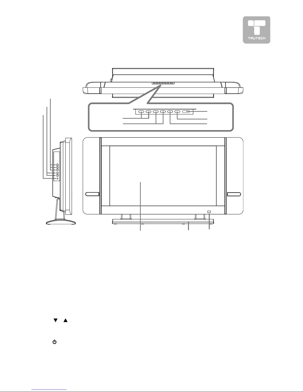
HEADPHONE jackHEADPHONE jack
HEADPHONE jackHEADPHONE jack
HEADPHONE jack
2)2)
2)2)
2)
YUV2 Audio Input Jacks (Left/YUV2 Audio Input Jacks (Left/
YUV2 Audio Input Jacks (Left/YUV2 Audio Input Jacks (Left/
YUV2 Audio Input Jacks (Left/
Right)Right)
Right)Right)
Right)
3)3)
3)3)
3)
YUV2 Component Video InputsYUV2 Component Video Inputs
YUV2 Component Video InputsYUV2 Component Video Inputs
YUV2 Component Video Inputs
(Y/P(Y/P
(Y/P(Y/P
(Y/P
BB
BB
B
/P/P
/P/P
/P
RR
RR
R
))
))
)
4)4)
4)4)
4)
– VOL + controls– VOL + controls
– VOL + controls– VOL + controls
– VOL + controls
Adjust the volume level and
highlight selections (Left & Right)
on the menu screen.
5)5)
5)5)
5)
//
//
/
buttons buttons
buttons buttons
buttons
Press to highlight selections (Up
& Down) on the menu screen.
6)6)
6)6)
6)
STANDBY/ON button STANDBY/ON button
STANDBY/ON button STANDBY/ON button
STANDBY/ON button
Turns the unit on and off.
7)7)
7)7)
7)
MENU buttonMENU button
MENU buttonMENU button
MENU button
Enter the Setup menu.
8)8)
8)8)
8)
INPUTINPUT
INPUTINPUT
INPUT
button button
button button
button
Select AV1, AV2, YUV1, YUV2,
PC IN.
9)9)
9)9)
9)
Color LCD ScreenColor LCD Screen
Color LCD ScreenColor LCD Screen
Color LCD Screen
10)10)
10)10)
10)
Removeable StandRemoveable Stand
Removeable StandRemoveable Stand
Removeable Stand
11)11)
11)11)
11)
STANDBY indicatorSTANDBY indicator
STANDBY indicatorSTANDBY indicator
STANDBY indicator
Indicates whether the unit is ON
or in STANDBY (OFF) mode.
Light On: The unit is in STANDBY.
Light Off: The unit is turned ON.
Remote Control SensorRemote Control Sensor
Remote Control SensorRemote Control Sensor
Remote Control Sensor
Do not block this sensor or the
remote control will not work.
UNIT REFERENCE GUIDEUNIT REFERENCE GUIDE
UNIT REFERENCE GUIDEUNIT REFERENCE GUIDE
UNIT REFERENCE GUIDE
1
2
3
9
10 11
TOP & FRONT VIEWTOP & FRONT VIEW
TOP & FRONT VIEWTOP & FRONT VIEW
TOP & FRONT VIEW
6
7
8
4
5
Page 8
8
BACK & BOTTOM VIEWBACK & BOTTOM VIEW
BACK & BOTTOM VIEWBACK & BOTTOM VIEW
BACK & BOTTOM VIEW
12
13 14 15 16
UNIT REFERENCE GUIDEUNIT REFERENCE GUIDE
UNIT REFERENCE GUIDEUNIT REFERENCE GUIDE
UNIT REFERENCE GUIDE
12)12)
12)12)
12)
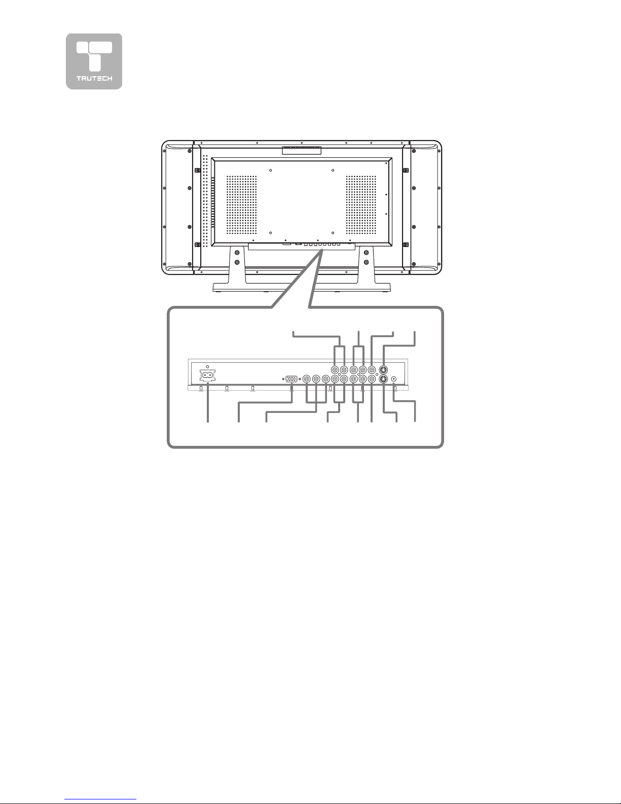
Power CordPower Cord
Power CordPower Cord
Power Cord
13) PC IN MONITOR/VGA jack13) PC IN MONITOR/VGA jack
13) PC IN MONITOR/VGA jack13) PC IN MONITOR/VGA jack
13) PC IN MONITOR/VGA jack
14)14)
14)14)
14)
YUV-IN1 Component VideoYUV-IN1 Component Video
YUV-IN1 Component VideoYUV-IN1 Component Video
YUV-IN1 Component Video
Inputs (Y/PInputs (Y/P
Inputs (Y/PInputs (Y/P
Inputs (Y/P
BB
BB
B
/P/P
/P/P
/P
RR
RR
R
))
))
)
15)15)
15)15)
15)
YUV-IN1 Audio Input JacksYUV-IN1 Audio Input Jacks
YUV-IN1 Audio Input JacksYUV-IN1 Audio Input Jacks
YUV-IN1 Audio Input Jacks
(Left / Right)(Left / Right)
(Left / Right)(Left / Right)
(Left / Right)
16)16)
16)16)
16)
AV-IN2 Audio Input JacksAV-IN2 Audio Input Jacks
AV-IN2 Audio Input JacksAV-IN2 Audio Input Jacks
AV-IN2 Audio Input Jacks
(Left / Right)(Left / Right)
(Left / Right)(Left / Right)
(Left / Right)
17)17)
17)17)
17)
AV-IN2 Video Input jackAV-IN2 Video Input jack
AV-IN2 Video Input jackAV-IN2 Video Input jack
AV-IN2 Video Input jack
18)18)
18)18)
18)
AV-IN2 S-Video InputAV-IN2 S-Video Input
AV-IN2 S-Video InputAV-IN2 S-Video Input
AV-IN2 S-Video Input
19)19)
19)19)
19)
PC IN Audio JackPC IN Audio Jack
PC IN Audio JackPC IN Audio Jack
PC IN Audio Jack
20) Audio Output Jacks (Left/Right)20) Audio Output Jacks (Left/Right)
20) Audio Output Jacks (Left/Right)20) Audio Output Jacks (Left/Right)
20) Audio Output Jacks (Left/Right)
21)21)
21)21)
21)
AV-IN1 Audio Input JacksAV-IN1 Audio Input Jacks
AV-IN1 Audio Input JacksAV-IN1 Audio Input Jacks
AV-IN1 Audio Input Jacks
(Left / Right)(Left / Right)
(Left / Right)(Left / Right)
(Left / Right)
22)22)
22)22)
22)
AV-IN1 Video Input JackAV-IN1 Video Input Jack
AV-IN1 Video Input JackAV-IN1 Video Input Jack
AV-IN1 Video Input Jack
23)23)
23)23)
23)
AV-IN1 S-Video InputAV-IN1 S-Video Input
AV-IN1 S-Video InputAV-IN1 S-Video Input
AV-IN1 S-Video Input
17 18 19
20
21 22 23
Page 9
9
CONNECTING TO A/V DEVICESCONNECTING TO A/V DEVICES
CONNECTING TO A/V DEVICESCONNECTING TO A/V DEVICES
CONNECTING TO A/V DEVICES
(VCR, Camcor(VCR, Camcor
(VCR, Camcor(VCR, Camcor
(VCR, Camcor
derder
derder
der
, Game System, etc.), Game System, etc.)
, Game System, etc.), Game System, etc.)
, Game System, etc.)
Connecting to Devices with an
S-Video Output
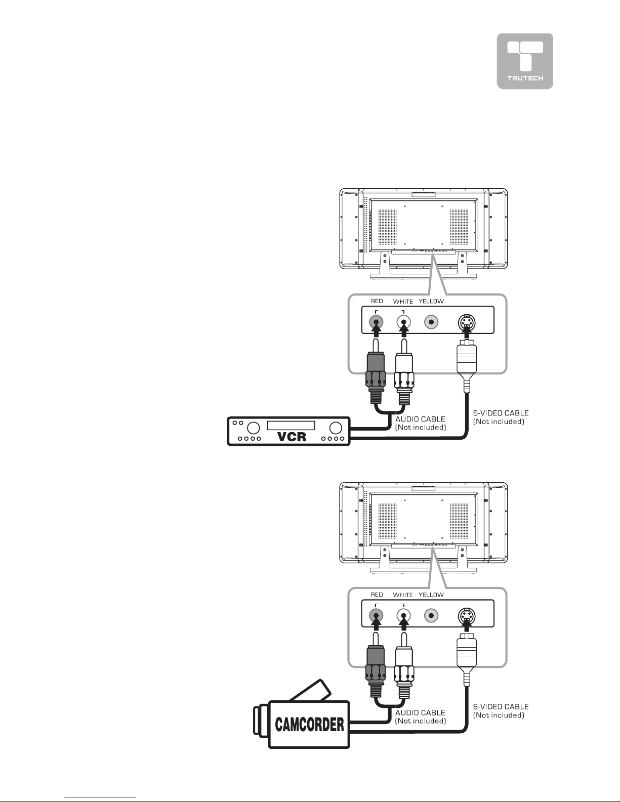
To connect to A/V devices such as a VCR or
camcorder:
- Connecting a VCR- Connecting a VCR
- Connecting a VCR- Connecting a VCR
- Connecting a VCR
Connect the right (red) and left (white) audio
output from the VCR to the right (red) and
left (white) input on this unit (Audio cable not
included).
Connect the S-VIDEO output from the VCR
to the S-VIDEO input on this unit (S-VIDEO
cable not included).
Make sure you connect both audio and video
from the same VCR to the same input (AV1/
AV2).
Note:Note:
Note:Note:
Note:
Please refer to the VCR’s user manual for
more information.
CONNECTIONSCONNECTIONS
CONNECTIONSCONNECTIONS
CONNECTIONS
- Connecting a camcorder- Connecting a camcorder
- Connecting a camcorder- Connecting a camcorder
- Connecting a camcorder
Connect the right (red) and left (white) audio
output from the camcorder to the right (red)
and left (white) input on this unit (Audio cable
not included).
Connect the S-VIDEO output from the
camcorder to the S-VIDEO input on this unit
(S-VIDEO cable not included).
Make sure you connect both audio and video
from the same camcorder to the same input
(AV1/AV2).
Note:Note:
Note:Note:
Note:
Please refer to the camcorder’s user manual
for more information.
S-VIDEO
VIDEO IN
RL
AUDIO
IN
S-VIDEO
VIDEO IN
RL
AUDIO
IN
Page 10
10
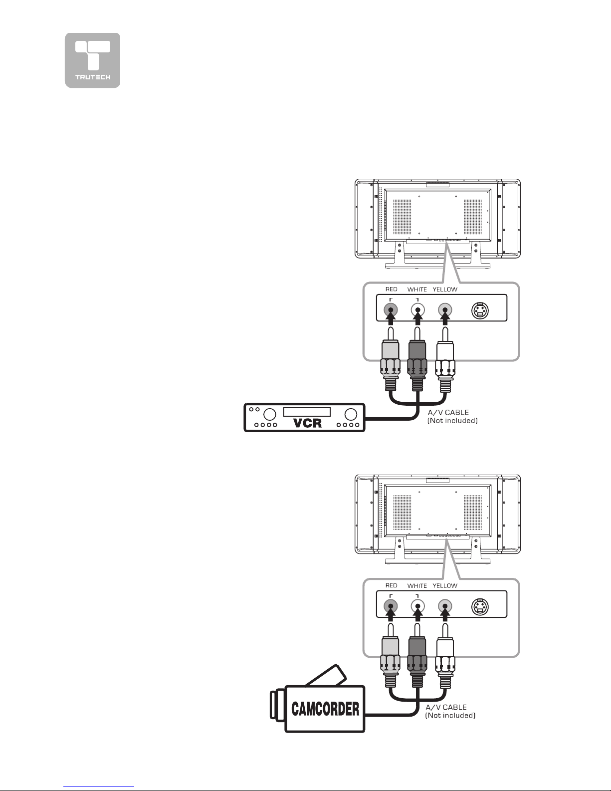
Connecting to Devices with a Composite (yellow RCA-type) Video
Output
To connect to A/V devices such as a VCR
or camcorder:
- Connecting a VCR- Connecting a VCR
- Connecting a VCR- Connecting a VCR
- Connecting a VCR
Connect the right (red) and left (white)
audio output from the VCR to the right
(red) and left (white) input on this unit
(Audio cable not included).
Connect the video (yellow) output from
the VCR to the video input on this unit
(Video cable not included).
Make sure you connect both audio and
video from the same VCR to the same
input (AV1/AV2).
Note:Note:
Note:Note:
Note:
Please refer to the VCR’s user manual
for more information.
CONNECTIONSCONNECTIONS
CONNECTIONSCONNECTIONS
CONNECTIONS
- Connecting a camcorder- Connecting a camcorder
- Connecting a camcorder- Connecting a camcorder
- Connecting a camcorder
Connect the right (red) and left (white)
audio output from the camcorder to the
right (red) and left (white) input on this
unit (Audio cable not included).
Connect the video (yellow) output from
the camcorder to the video input on this
unit (Video cable not included).
Make sure you connect both audio and
video from the same camcorder to the
same input (AV1/AV2).
Note:Note:
Note:Note:
Note:
Please refer to the camcorder‘s user
manual for more information.
S-VIDEO
VIDEO IN
RL
AUDIO
IN
S-VIDEO
VIDEO IN
RL
AUDIO
IN
Page 11
11
CONNECTIONSCONNECTIONS
CONNECTIONSCONNECTIONS
CONNECTIONS
CONNECTING TO CONNECTING TO
CONNECTING TO CONNECTING TO
CONNECTING TO
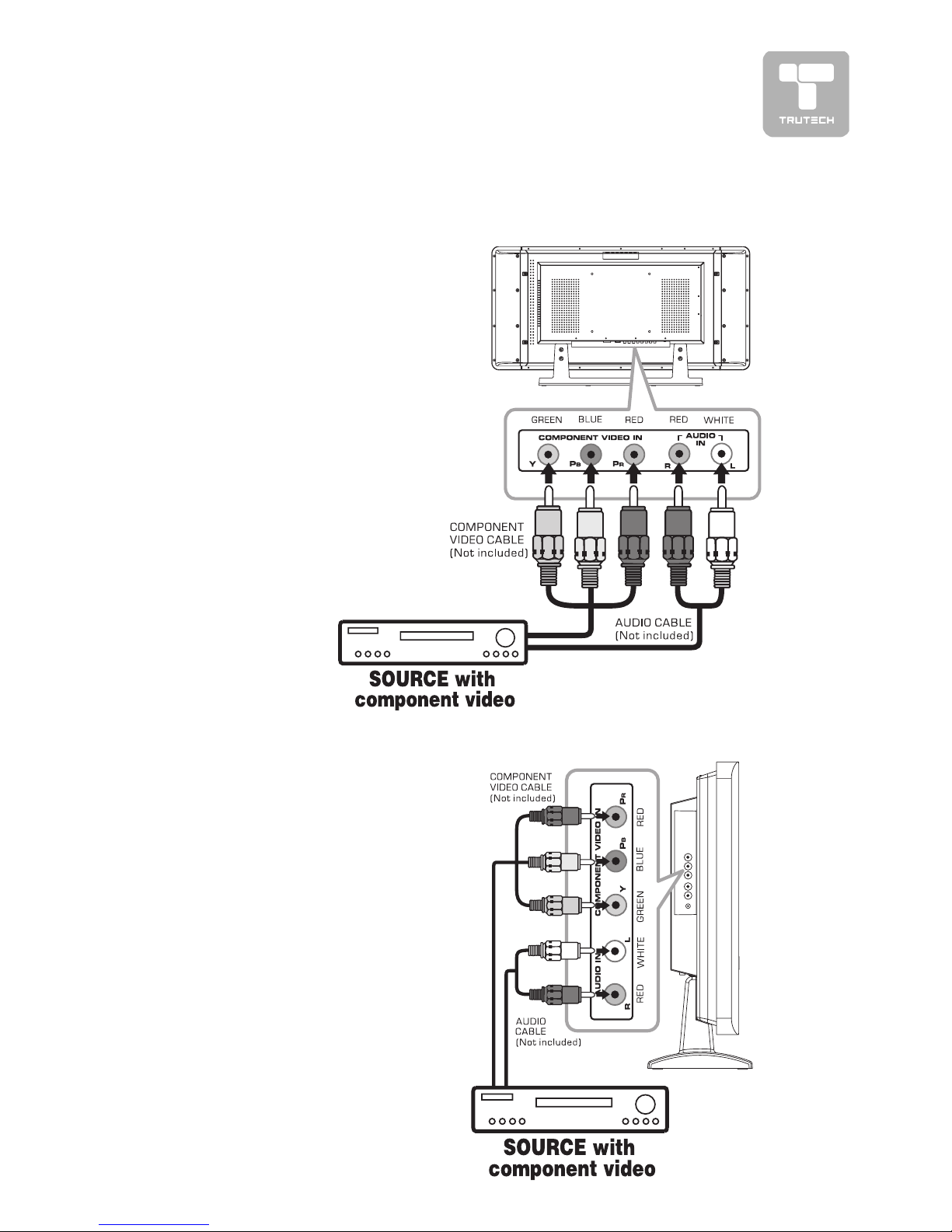
SOURCES WITH COMPONENT VIDEO OUTPUTSOURCES WITH COMPONENT VIDEO OUTPUT
SOURCES WITH COMPONENT VIDEO OUTPUTSOURCES WITH COMPONENT VIDEO OUTPUT
SOURCES WITH COMPONENT VIDEO OUTPUT
(DVD - only 480i, 480p, 720p & 1080i are supported)(DVD - only 480i, 480p, 720p & 1080i are supported)
(DVD - only 480i, 480p, 720p & 1080i are supported)(DVD - only 480i, 480p, 720p & 1080i are supported)
(DVD - only 480i, 480p, 720p & 1080i are supported)
Devices with component video output
must be connected to the YUV1 input:
Connect the three video outputs (Y,
Pb, Pr) from the source to the
corresponding video inputs on this unit
(Component video cable not included).
Connect the right (red) and left (white)
audio output from the source to the
right (red) and left (white) input on this
unit (Audio cable not included).
Make sure you connect both audio and
video from the same source to YUV1.
Note:Note:
Note:Note:
Note:
Please refer to the user manual for
your component video source for more
information and connection details.
Devices with component video output
must be connected to the YUV2 input:
Connect the three video outputs (Y,
Pb, Pr) from the source to the
corresponding video inputs on this unit
(Component video cable not included).
Connect the right (red) and left (white)
audio output from the source to the
right (red) and left (white) input on this
unit (Audio cable not included).
Make sure you connect both audio and
video from the same source to YUV2.
Note:Note:
Note:Note:
Note:
Please refer to the user manual for
your component video source for more
information and connection details.
Page 12
12
CONNECTIONSCONNECTIONS
CONNECTIONSCONNECTIONS
CONNECTIONS
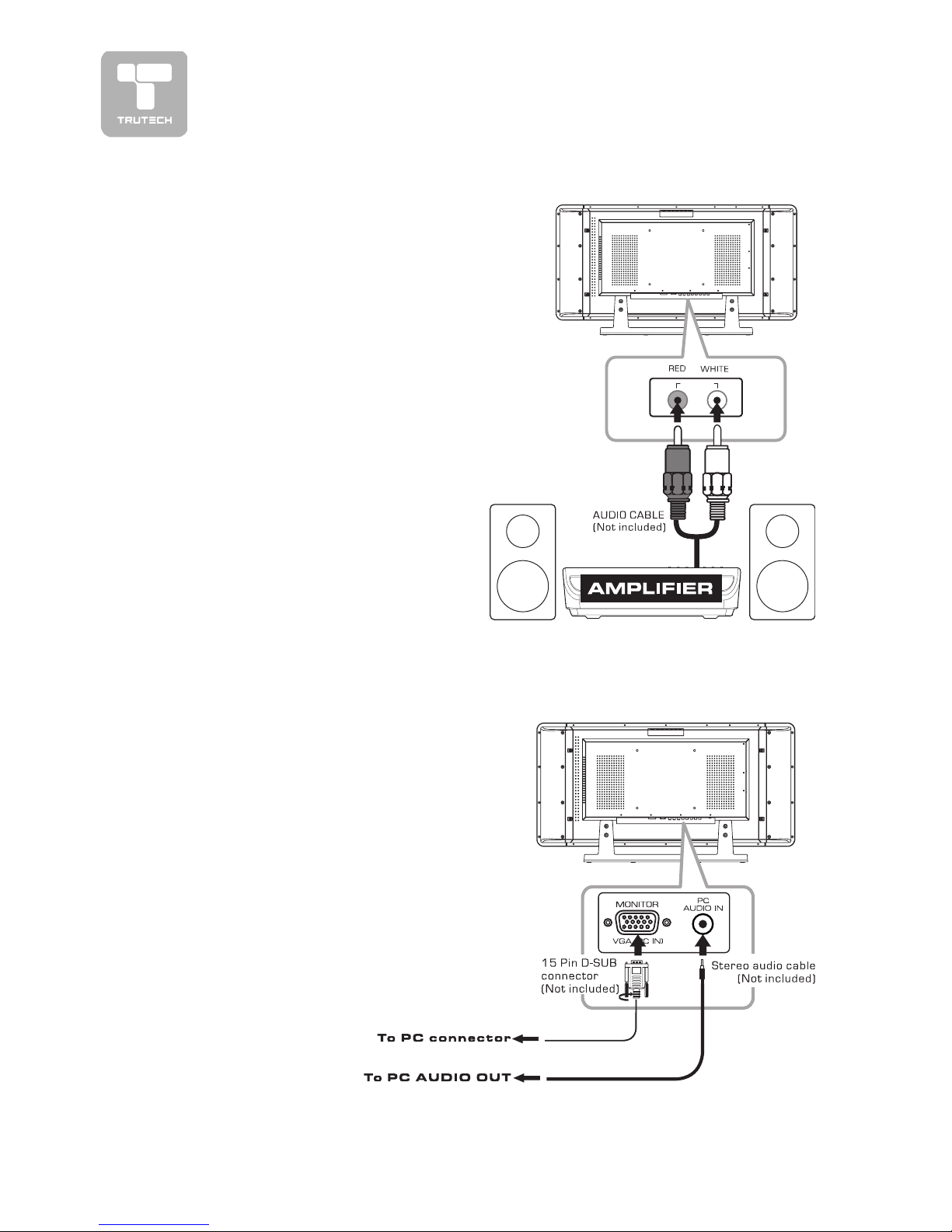
CONNECTING A PCCONNECTING A PC
CONNECTING A PCCONNECTING A PC
CONNECTING A PC
Connect the 15-pin D-SUB PC/VGA
connector from your computer to the
15-pin D-SUB PC/VGA input on this
unit using a monitor cable (not
included).
Connect a stereo audio cable (not
included) to the PC AUDIO IN jack on
the bottom of this unit, and the other
end to the AUDIO OUT jack on your
computer’s sound card.
CONNECTING AN AUDIO AMPLIFIERCONNECTING AN AUDIO AMPLIFIER
CONNECTING AN AUDIO AMPLIFIERCONNECTING AN AUDIO AMPLIFIER
CONNECTING AN AUDIO AMPLIFIER
This connection allows you to use an audio
amplifier and external speakers.
Connect the right (red) and left (white)
audio OUTPUT from this unit to the right
(red) and left (white) audio INPUT on your
amplifier. Refer to your amplifier’s user
manual for more information.
Note :Note :
Note :Note :
Note :
To control the audio, both the unit and
the amplifier must be turned on, and the
volume of the amplifier must be set above
0, or you will not hear any sound.
If you want to hear the volume
of the amplifier only, press the
volume – button on the unit to
decrease the volume or press the
MUTE button on the remote control
to turn off the sound.
RL
AUDIO
OUT
Page 13
13
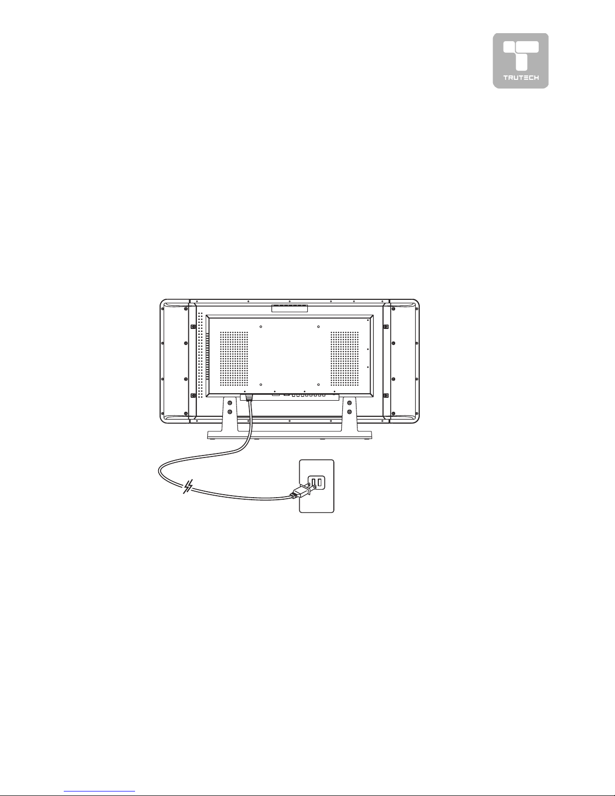
CONNECTING THE POWER CORDCONNECTING THE POWER CORD
CONNECTING THE POWER CORDCONNECTING THE POWER CORD
CONNECTING THE POWER CORD
• Plug the power cord into an outlet.
• Press the
STANDBY/ONSTANDBY/ON
STANDBY/ONSTANDBY/ON
STANDBY/ON button on top of the unit or on the remote control
to turn on the unit.
Note:Note:
Note:Note:
Note:
• Be sure the AC power cord is disconnected and all functions are off before
making connections.
• Make sure that all the components are connected correctly.
•
To prevent electrical shock, match wide blade of plug to wide slot on outlet,To prevent electrical shock, match wide blade of plug to wide slot on outlet,
To prevent electrical shock, match wide blade of plug to wide slot on outlet,To prevent electrical shock, match wide blade of plug to wide slot on outlet,
To prevent electrical shock, match wide blade of plug to wide slot on outlet,
and fully insert.and fully insert.
and fully insert.and fully insert.
and fully insert.
• When you are not going to use the unit for a long period of time, disconnect
the power cord.
CONNECTIONSCONNECTIONS
CONNECTIONSCONNECTIONS
CONNECTIONS
Page 14
14
INSTINST
INSTINST
INST
ALLAALLA
ALLAALLA
ALLA
TIONTION
TIONTION
TION
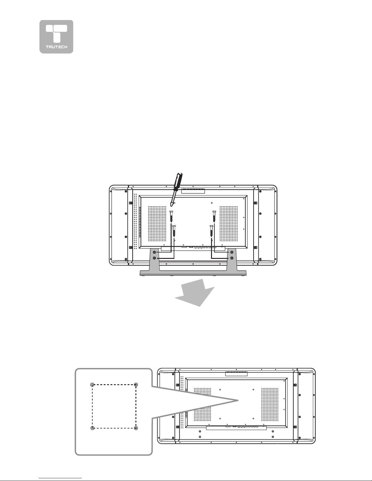
MOUNTING ON THE WALLMOUNTING ON THE WALL
MOUNTING ON THE WALLMOUNTING ON THE WALL
MOUNTING ON THE WALL
This unit is VESA-compliant, and is designed to be wall-mounted with a VESAcompliant 7.9” x 7.9” (200mm x 200mm) mounting kit designed for flat-panel
TVs (sold separately). Mount this unit according to the directions included with
the mounting kit.
REMOVING THE BASE STREMOVING THE BASE ST
REMOVING THE BASE STREMOVING THE BASE ST
REMOVING THE BASE ST
ANDAND
ANDAND
AND
WARNING: The LCD Display is very fragile, and must be protected at all times
when removing the base stand. Be sure that no hard or sharp objects, or
anything that could scratch or damage the LCD display, come in contact with it.
Do NOT place pressure on the rear of the unit at any time because the screen
could crack.
1. Disconnect any cables or cords connected to the unit.
2. Lay the unit down on a flat surface, so the back side is facing up, making
sure to place a soft cushioned material (such as a pillow or thick piece of
foam) beneath the screen.
3. Remove the four screws and then remove the BASE STAND from the unit.
Four mounting
holes
7.9"
7.9"
Page 15
15
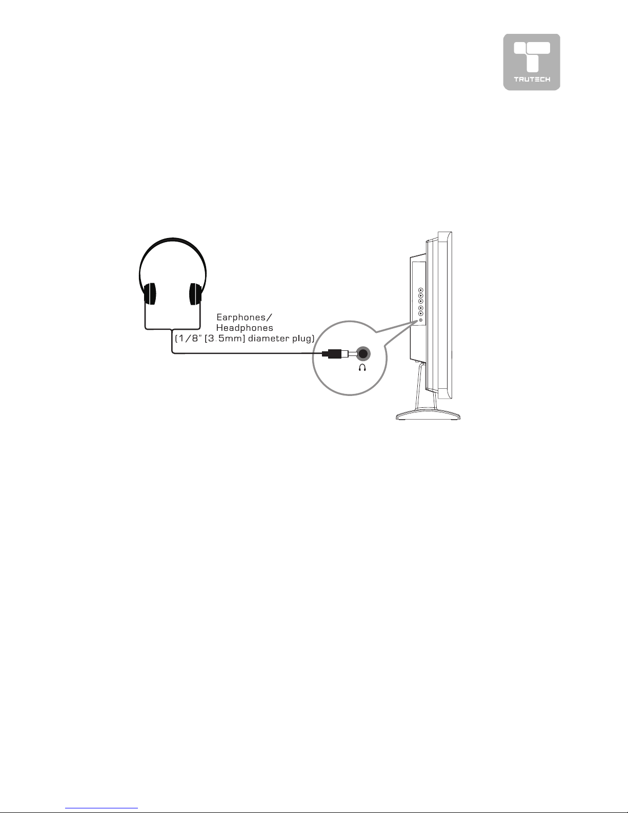
• Turn down the volume before connecting headphones to the unit, then
adjust the volume to your desired level.
• When headphones are connected, no sound will come from the front speakers.
Note:Note:
Note:Note:
Note:
• Avoid listening to sound at high levels for prolonged periods of time. This
may be harmful to you and may cause hearing loss.
USING HEADPHONESUSING HEADPHONES
USING HEADPHONESUSING HEADPHONES
USING HEADPHONES
Page 16
16
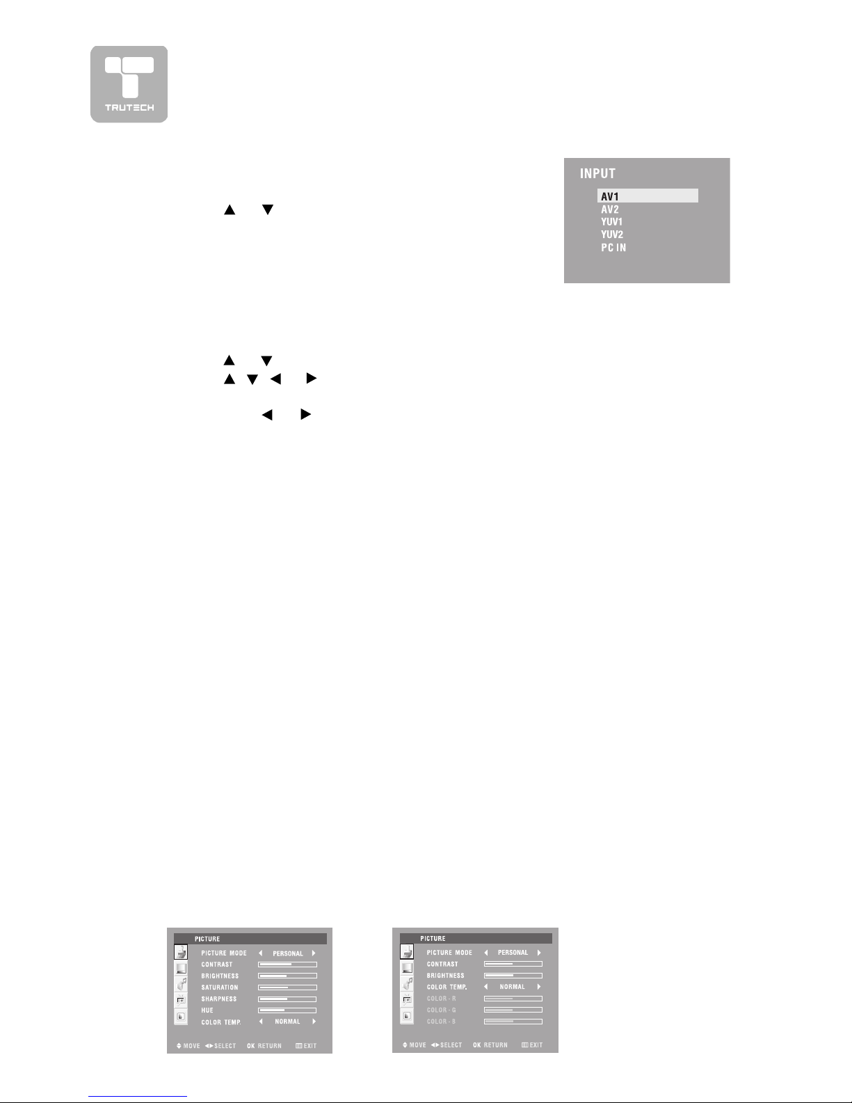
MENU SETUP
PICTURE MENUPICTURE MENU
PICTURE MENUPICTURE MENU
PICTURE MENU
1. Press the
MENUMENU
MENUMENU
MENU button.
2. Use or button to select the
Picture Picture
Picture Picture
Picture menu.
3. Use
, , or button to select the options
(Picture Mode , Contrast,(Picture Mode , Contrast,
(Picture Mode , Contrast,(Picture Mode , Contrast,
(Picture Mode , Contrast,
Brightness, Saturation, Sharpness, Hue & Color TBrightness, Saturation, Sharpness, Hue & Color T
Brightness, Saturation, Sharpness, Hue & Color TBrightness, Saturation, Sharpness, Hue & Color T
Brightness, Saturation, Sharpness, Hue & Color T
emp)emp)
emp)emp)
emp) and adjust them
using the
or buttons. (The screen will change to your desired setting).
4. Repeat step 3 to adjust other options.
5. Press the OK button to return to normal screen, press the
MENUMENU
MENUMENU
MENU button to
exit menu.
Note :Note :
Note :Note :
Note : You can also select simply by pressing the
PICTUREPICTURE
PICTUREPICTURE
PICTURE button.
•
Picture ModePicture Mode
Picture ModePicture Mode
Picture Mode : Select from preset screen display settings to match the type
of show you are watching (Natural, Bright, Soft & Personal).
When you select the Picture mode to Personal, the options below will be
displayed.
•
ContrastContrast
ContrastContrast
Contrast : Adjust to sharpen the picture quality. The black portions of the
picture become richer in darkness and the white become brighter.
•
BrightnessBrightness
BrightnessBrightness
Brightness : Adjust to brighten the darkest parts of the picture.
•
SaturationSaturation
SaturationSaturation
Saturation : Adjust the saturation of a color.
•
SharpnessSharpness
SharpnessSharpness
Sharpness : Adjust the sharpness level to improve detail in the picture.
•
HueHue
HueHue
Hue : Adjust the hue of the picture. (Toward purple / Toward green)
•
Color TColor T
Color TColor T
Color T
empemp
empemp
emp : Adjust the three color temperature of the picture. Select Normal
(balanced) / Warm (red white)/Cool (blue white) mode.
AV1/AV2/YUV1/
YUV2 mode
PC IN mode
MAIN MENUMAIN MENU
MAIN MENUMAIN MENU
MAIN MENU
1. Press the
INPUTINPUT
INPUTINPUT
INPUT button.
2. Use or button to select the options
(AV1,(AV1,
(AV1,(AV1,
(AV1,
AV2, YUV1, YUV2, PC IN)AV2, YUV1, YUV2, PC IN)
AV2, YUV1, YUV2, PC IN)AV2, YUV1, YUV2, PC IN)
AV2, YUV1, YUV2, PC IN) . The screen will change
to your desired setting.
In PC IN modeIn PC IN mode
In PC IN modeIn PC IN mode
In PC IN mode
When you select the Picture mode to Personal, the options of Contrast and
Brightness will be displayed.
The color temperature setting options will be shown Normal (balanced)/Warm
(red white)/Cool (blue white)/User (Color-R, Color-G, Color-B). Contrast and
brightness settings operate only.
• Resolution : 1280 x 1024 max
• Refresh Frequency : 75Hz max
Page 17
17
MENU SETUP
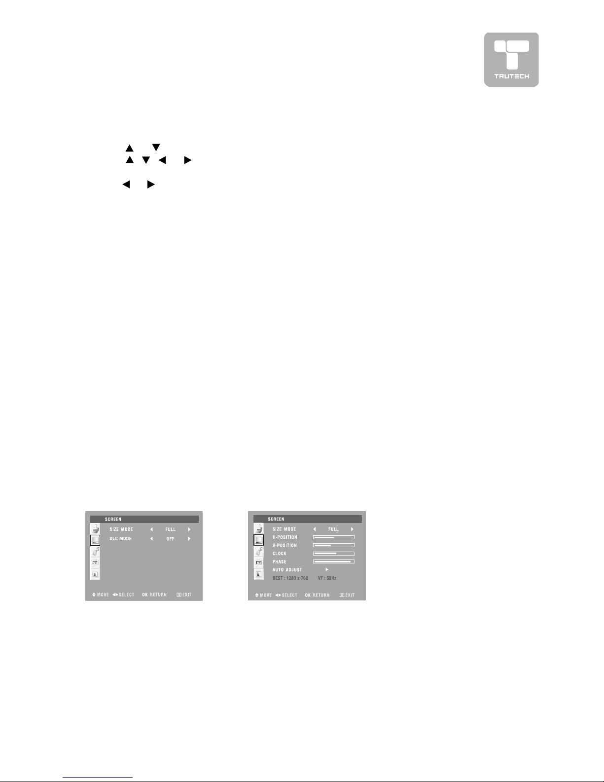
SCREEN MENUSCREEN MENU
SCREEN MENUSCREEN MENU
SCREEN MENU
1. Press the
MENUMENU
MENUMENU
MENU button.
2. Use
or button to select the
Screen Screen
Screen Screen
Screen menu.
3. Use
, , or button to select the options
(Size mode, DLC mode, H-(Size mode, DLC mode, H-
(Size mode, DLC mode, H-(Size mode, DLC mode, H-
(Size mode, DLC mode, H-
Position, V-Position, Clock, Phase, Auto Adjust) Position, V-Position, Clock, Phase, Auto Adjust)
Position, V-Position, Clock, Phase, Auto Adjust) Position, V-Position, Clock, Phase, Auto Adjust)
Position, V-Position, Clock, Phase, Auto Adjust) and adjust them using
the or buttons. (The screen will change to your desired setting).
4. Repeat step 3 to adjust other options.
5. Press the OK button to return to normal screen, press the
MENUMENU
MENUMENU
MENU button to
exit menu.
AV1/AV2/YUV1/
YUV2 mode PC IN mode
•
Size modeSize mode
Size modeSize mode
Size mode :
To select the picture format which best corresponds to your viewing
requirements.
Full --> Normal --> Zoom 1 --> Zoom 2
Note :Note :
Note :Note :
Note : You can also select simply by pressing the
FORMAFORMA
FORMAFORMA
FORMA
TT
TT
T button.
In PC IN modeIn PC IN mode
In PC IN modeIn PC IN mode
In PC IN mode
•
Size modeSize mode
Size modeSize mode
Size mode : Select the picture format to ‘Full’ & ‘Normal’.
•
H-positionH-position
H-positionH-position
H-position : Center the image by moving it left or right.
•
V-positionV-position
V-positionV-position
V-position : Center the image by moving it up or down.
•
ClockClock
ClockClock
Clock : Adjusts when the image flickers with vertical stripes.
•
PhasePhase
PhasePhase
Phase : Adjusts when characters have low contrast or when the image
flickers.
•
Auto AdjustAuto Adjust
Auto AdjustAuto Adjust
Auto Adjust : Adjusts when characters have low contrast or when the image
flickers automatically.
•
DLC mode (Dynamic Light Control Mode)DLC mode (Dynamic Light Control Mode)
DLC mode (Dynamic Light Control Mode)DLC mode (Dynamic Light Control Mode)
DLC mode (Dynamic Light Control Mode) :
To adjust the brightness of the screen automatically.
Page 18

18
Experiment with different sound settings until you find the settings you prefer.
•
Sound modeSound mode
Sound modeSound mode
Sound mode : Select from preset sound settings (Normal, News, Music,
Movie, Personal) to match the type of show you are watching.
•
BalanceBalance
BalanceBalance
Balance : Adjust the balance level toward the left or right speakers.
When you select the Sound mode to Personal, the options below will be displayed.
•
BassBass
BassBass
Bass : Adjust the bass range.
•
TT
TT
T
rr
rr
r
ebleeble
ebleeble
eble : Adjust the treble range.
SOUND MENUSOUND MENU
SOUND MENUSOUND MENU
SOUND MENU
1. Press the
MENUMENU
MENUMENU
MENU button.
2. Use
or button to select the
Sound Sound
Sound Sound
Sound menu.
3. U se
, , or button to select the options
(Sound mode, Bass, T(Sound mode, Bass, T
(Sound mode, Bass, T(Sound mode, Bass, T
(Sound mode, Bass, T
rr
rr
r
eble &eble &
eble &eble &
eble &
Balance)Balance)
Balance)Balance)
Balance) and adjust them using the
or buttons. (The screen will change
to your desired setting).
4. Repeat step 3 to adjust other options.
5. Press the OK button to return to normal screen, press the
MENUMENU
MENUMENU
MENU button to
exit menu.
Note :Note :
Note :Note :
Note : You can also select simply by pressing the
SOUNDSOUND
SOUNDSOUND
SOUND button.
AV1/AV2/YUV1/
YUV2/PC IN mode
MENU SETUP
Page 19
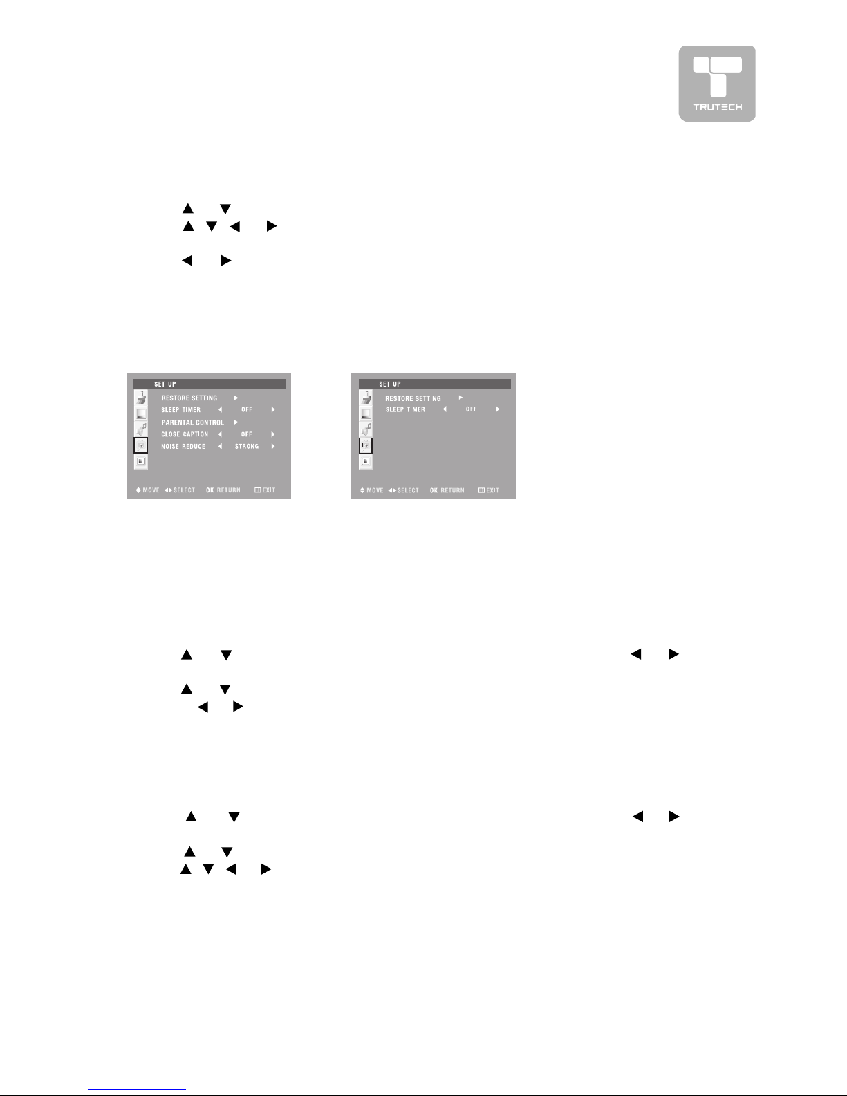
19
MENU SETUP
SETUP MENUSETUP MENU
SETUP MENUSETUP MENU
SETUP MENU
1. Press the
MENUMENU
MENUMENU
MENU button.
2. Use
or button to select the
Set up Set up
Set up Set up
Set up menu.
3. Use
, , or button to select the options
(Restore setting, Sleep(Restore setting, Sleep
(Restore setting, Sleep(Restore setting, Sleep
(Restore setting, Sleep
timertimer
timertimer
timer
, Par, Par
, Par, Par
, Par
ental contrental contr
ental contrental contr
ental contr
ol, Close caption, Noise rol, Close caption, Noise r
ol, Close caption, Noise rol, Close caption, Noise r
ol, Close caption, Noise r
educe)educe)
educe)educe)
educe) and adjust them using
the or buttons. (The screen will change to your desired setting).
4. Repeat step 3 to adjust other options.
5. Press the OK button to return to normal screen, press the
MENUMENU
MENUMENU
MENU button
to exit menu.
AV1/AV2 mode
YUV1/YUV2/
PC IN mode
TIMERS SETTINGTIMERS SETTING
TIMERS SETTINGTIMERS SETTING
TIMERS SETTING
To select the sleep timer to turn off the unit automatically.
1. Press the
MENUMENU
MENUMENU
MENU button.
2. Use
or button to select the
Set upSet up
Set upSet up
Set up menu, and then press or
button to enter.
3. Use
or button to select
Sleep timerSleep timer
Sleep timerSleep timer
Sleep timer.
4. Use
, , or button to select the number of minutes
(Off --> 5Min -->(Off --> 5Min -->
(Off --> 5Min -->(Off --> 5Min -->
(Off --> 5Min -->
10Min --> 15Min --> 30Min --> 45Min --> 60Min).10Min --> 15Min --> 30Min --> 45Min --> 60Min).
10Min --> 15Min --> 30Min --> 45Min --> 60Min).10Min --> 15Min --> 30Min --> 45Min --> 60Min).
10Min --> 15Min --> 30Min --> 45Min --> 60Min).
5. Press the OK button to return to normal screen, press the
MENUMENU
MENUMENU
MENU button
to exit menu.
Note :Note :
Note :Note :
Note : You can also select simply by pressing the
SLEEPSLEEP
SLEEPSLEEP
SLEEP button.
RESTORE SETTINGRESTORE SETTING
RESTORE SETTINGRESTORE SETTING
RESTORE SETTING
If you reset the AV to the factory settings, all your present settings on picture &
sound will be erased and replaced by the factory’s default settings. However,
picture setting in PC mode and parental setting will not be erased.
1. Press the
MENUMENU
MENUMENU
MENU button.
2. Use
or button to select the
Set up Set up
Set up Set up
Set up menu, and then press or
button to enter.
3. Use
or button to select the option of RESTORE SETTING and then
press
or button to set ‘ON’ for high detail in black portions.
Page 20
20
MENU SETUP
PARENTPARENT
PARENTPARENT
PARENT
AL CONTROLAL CONTROL
AL CONTROLAL CONTROL
AL CONTROL
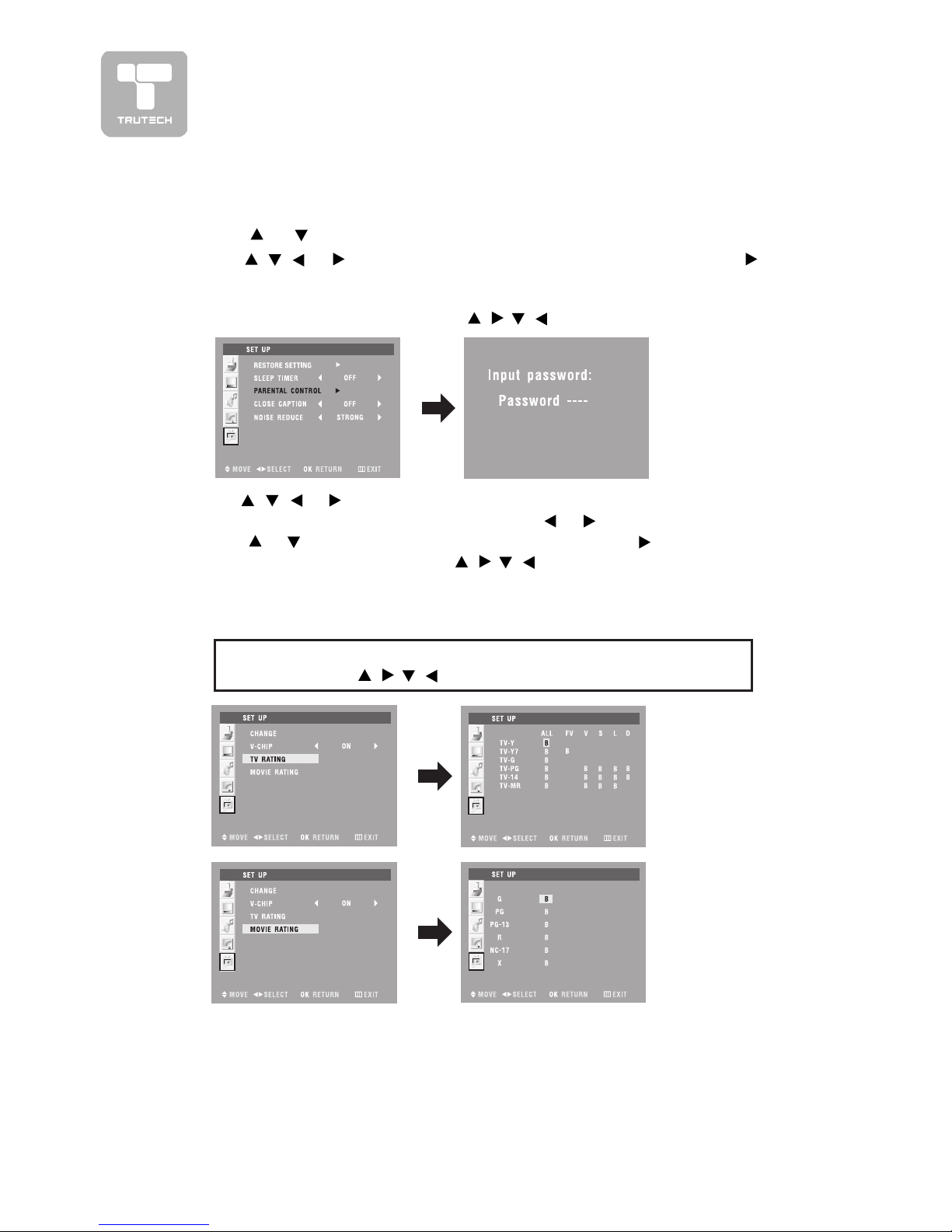
1. Press the MENU button.
2. Use
or button to select the
Set upSet up
Set upSet up
Set up menu.
3. Use
, , or button to select the
Parental controlParental control
Parental controlParental control
Parental control and then press button
to confirm.
4. Enter a 4-digit lock code. Once entered, the screen will enter the Parental menu.
The factory preset lock code is “
“.
5. Use
, , or button to select the options
(Change, V-chip, TV rating,(Change, V-chip, TV rating,
(Change, V-chip, TV rating,(Change, V-chip, TV rating,
(Change, V-chip, TV rating,
Movie rating)Movie rating)
Movie rating)Movie rating)
Movie rating) and adjust them using the
or buttons.
6. Use
or button to select the
ChangeChange
ChangeChange
Change and then press button to change the
password . (Note : Only press
& OK button to set the password,
other button is not available.)
7. Press the MENU button to return to normal screen.
Note :Note :
Note :Note :
Note : In AV1 & AV2 mode only, this option is available.
TV RatingTV Rating
TV RatingTV Rating
TV Rating
TV-Y : Suitable for children ages 2-6.
TV-Y7 : Suitable for children ages 7 and
above.
TV-G : Suitable for all ages.
TV-PG : Parental guidance suggested.
TV-14 : Parents strongly cautioned.
TV-MR : Mature audience only.
Move RatingMove Rating
Move RatingMove Rating
Move Rating
G : General audiences.
PG : Parental guidance suggested.
PG-13 : Parents strongly cautioned.
R : Restricted.
NC-17 : No one 17 and under admitted.
X : X is an older rating that is unified
with NC-17 but may be encoded
in the data of older movies.
If you forget the password,If you forget the password,
If you forget the password,If you forget the password,
If you forget the password,
enter “enter “
enter “enter “
enter “
“ to unlock parental control. “ to unlock parental control.
“ to unlock parental control. “ to unlock parental control.
“ to unlock parental control.
Page 21

21
MENU SETUP
CLOSED CAPTIONINGCLOSED CAPTIONING
CLOSED CAPTIONINGCLOSED CAPTIONING
CLOSED CAPTIONING
Allows conversations, narration, and sound effects in home videos to be viewed as
captions on the screen.
1. Press the
MENUMENU
MENUMENU
MENU button.
2. Use
or button to select the
Setup Setup
Setup Setup
Setup menu, and then press or button
to enter.
3. Use
or button to select the
Close captionClose caption
Close captionClose caption
Close caption.
4. U se
or button to select the options
(OFF(OFF
(OFF(OFF
(OFF
, CC1 --> CC4, TEXT 1 --> TEXT, CC1 --> CC4, TEXT 1 --> TEXT
, CC1 --> CC4, TEXT 1 --> TEXT, CC1 --> CC4, TEXT 1 --> TEXT
, CC1 --> CC4, TEXT 1 --> TEXT
4, CC1MUTE, XDS)4, CC1MUTE, XDS)
4, CC1MUTE, XDS)4, CC1MUTE, XDS)
4, CC1MUTE, XDS) and adjust them using the
or buttons. (The screen
will change to your desired setting)
5. Press the OK button to return to normal screen, press the
MENUMENU
MENUMENU
MENU button to
exit menu.
Note :Note :
Note :Note :
Note : In AV1 & AV2 mode only, this option is available.
Note :Note :
Note :Note :
Note :
• The Closed Captioning broadcasts can be viewed in two modes : CAPTION
and TEXT. For each mode, four channels are available :
CC1 : Caption mode for CH1 data TEXT1 : Text mode for CH1 data
CC2 : Caption mode for CH2 data TEXT2 : Text mode for CH2 data
CC3 : Caption mode for CH3 data TEXT3 : Text mode for CH3 data
CC4 : Caption mode for CH4 data TEXT4 : Text mode for CH4 data
• If you select CC1MUTE, the sound will be muted and the captions will
appear automatically when you press the
MUTEMUTE
MUTEMUTE
MUTE button. Press the MUTE
button again to turn on the sound and the captions will disappear. Select
XDS to extend data services.
• Press the
CCCC
CCCC
CC button to directly turn on CLOSED CAPTIONING .
NOISE REDUCTIONNOISE REDUCTION
NOISE REDUCTIONNOISE REDUCTION
NOISE REDUCTION
1. Press the
MENUMENU
MENUMENU
MENU button.
2. Use
or button to select the
Set up Set up
Set up Set up
Set up menu, and then press or
button to enter.
3. Use
or button to select
Noise reduceNoise reduce
Noise reduceNoise reduce
Noise reduce.
4. Use
or button to select the options
(Strong, Off, Weak)(Strong, Off, Weak)
(Strong, Off, Weak)(Strong, Off, Weak)
(Strong, Off, Weak) and adjust
them using the
or buttons. (The screen will change to your desired
setting).
5. Repeat step 3 to adjust other options.
6. Press the OK button to return to normal screen, press the
MENUMENU
MENUMENU
MENU button to
exit menu.
Note :Note :
Note :Note :
Note : In AV1 & AV2 mode only, this option is available.
Page 22
22
MENU SETUP
Note:Note:
Note:Note:
Note:
••
••
•
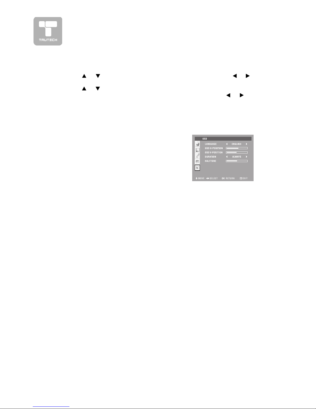
Language Language
Language Language
Language :
Select from English/Français/Español.
••
••
•
OSD h-position OSD h-position
OSD h-position OSD h-position
OSD h-position :
Move the picture of setup menu left or
right.
••
••
•
OSD v-position OSD v-position
OSD v-position OSD v-position
OSD v-position :
Move the picture setup menu up or
down.
••
••
•
Duration Duration
Duration Duration
Duration :
Select the time of setup menu on screen
(Always -> 15S -> 30S -> 45S -> 60S).
••
••
•
Halftone Halftone
Halftone Halftone
Halftone :
To change the tone on the picture of
setup menu.
ON SCREEN DISPLAON SCREEN DISPLA
ON SCREEN DISPLAON SCREEN DISPLA
ON SCREEN DISPLA
Y SETTINGY SETTING
Y SETTINGY SETTING
Y SETTING
1. Press the
MENUMENU
MENUMENU
MENU button.
2. Use
or button to select the
OSD OSD
OSD OSD
OSD menu, and then press or button
to enter.
3. U se or button to select the options
(Language, OSD h-position, OSD v-(Language, OSD h-position, OSD v-
(Language, OSD h-position, OSD v-(Language, OSD h-position, OSD v-
(Language, OSD h-position, OSD v-
position, Duration, Halftone)position, Duration, Halftone)
position, Duration, Halftone)position, Duration, Halftone)
position, Duration, Halftone) and adjust them using the
or buttons.
(The screen will change to your desired setting).
4. Repeat step 3 to adjust other options.
5. Press the OK button to return to normal screen, press the
MENUMENU
MENUMENU
MENU button to
exit menu.
Page 23

23
• Increase the volume.
• Check whether the mute function has been activated
on the Remote Control.
• Check the Picture setting within the Setup menu.
• Check to make sure the program you are watching is
broadcast in Color and not Black & White.
• Make sure the unit is plugged in and turned on.
• Increase the volume.
• Make sure the audio/video source device is working
properly.
• Make sure all cables are connected firmly.
• Make sure there are no unshielded electrical devices
nearby that are causing interference.
• Turn the unit off for 30 minutes, then try it again.
No sound.
Black and white
picture.
No picture or sound.
Colored patches of
picture.
TROUBLE SHOOTING GUIDE
SYMPTOM CAUSE (AND REMEDY)
• Ensure that the AC power cord is connected.
• Turn on the unit.
• Remove any obstacles between the remote and the
unit.
• Use the remote near the unit.
• Point the remote at the remote sensor on the unit.
• Replace the battery in the remote with a new one.
No power.
The remote does
not function.
Page 24

Printed in China
811-173291-011
 Loading...