

TruTalk MURS-25 Operating Instructions Manual
MURS-25
Operating Instructions


Table of Contents
I. FCC RF Exposure Compliance Requirements........... 1
FCC Warning........................................................... 2
II. FCC RF Exposure Information.................................... 2
III. About Topaz3............................................................... 3
IV. About Your MURS-25 Radio....................................... 4
V. Unpacking and Checking Equipment........................ 5
VI. Radio Control Buttons / Operation Features............ 6
Backlit LCD Features.............................................. 8
VII. Getting Started.............................................................. 10
Charging the NiMH Battery Pack......................... 10
Attaching and Removing the Battery Pack.......... 12
Installing the Antenna............................................ 13
Installing the Belt Clip............................................ 13
Installing the Speaker Mic. Jack Cover................ 13
Attaching the Optional Speaker Mic................... 14
VIII. Radio Operation........................................................... 15
Power On................................................................ 15
Normal Transmit and Receive.............................. 16
IX. Channel Frequency Selection..................................... 17
X. CTCSS / DCS Tone Signaling....................................... 18
XI. Weather (WX) Mode.................................................... 22
XII. Scan Functions............................................................. 23
Talk Back Scan........................................................ 23
Vacant Channel (VC) Scan.................................... 24
Weather (WX) Scan................................................ 24
Nuisance Delete..................................................... 25
XIII. Audible Tone................................................................ 26
XIV. Busy Channel Lockout................................................. 27
XV. Time-Out-Timer............................................................ 28
XVI. Talk Confirmation Tone.............................................. 29
XVII. VOX (Voice Operated Transmission)........................ 30
i

Table of Contents, continued
XVIII. Carrier Lockout.......................................................... 31
XIX. Weather Alert............................................................. 32
XX. Function Lock............................................................. 33
XXI. Other Radio Functions.............................................. 34
Battery Save........................................................ 34
Low Battery Warning........................................ 35
XXII. Compatible MURS-25 Accessories.......................... 35
XXIII. Licensing, Safety and Service Information............. 36
FCC Licensing..................................................... 36
Safety Information............................................. 36
Service................................................................. 36
XXIV. Maintenance............................................................... 37
XXV. Warranty Service Instructions................................. 38
XXVI. Software Copyrights.................................................. 39
XXVII. Warranty Statement.................................................. 40
ii

Contenido
I. Requerimientos de Obediencia a la Exposición
de RF del FCC......................................................... 42
Advertencia de FCC.............................................. 43
II. Información de Exposición de FCC.......................... 43
III. Acerca de Topaz3....................................................... 45
IV. Información Acerca de su MURS-25........................ 46
V. Desempaque y Verificación del Equipo................... 47
VI. Botones de Control del Radio / Rasgos de
Funcionamiento.................................................... 48
Características del LCD con Luz de Fondo........ 50
VII. Preparación.................................................................. 52
Cargador de Batería de NiMH............................. 52
Instalación y Retiro de la Batería......................... 54
Instalación de la Antena....................................... 55
Instalación del Clip de Cinturón......................... 55
Instalación de la Cubierta de la Clavija de
Conexión de Micrófono de Altavoz................. 55
Agregando el Micrófono de Altavo Opcional... 56
VIII. Funcionamiento del Radio......................................... 57
Encienda................................................................. 57
Transmisión y Recepción Normal ...................... 58
IX. Selección de Frecuencia de Canales......................... 59
X. Señalización de Tono CTCSS / DCS.......................... 60
XI. Modo de Tiempo (WX) .............................................. 64
XII. Funciones de Búsqueda............................................. 65
Búsqueda de Respuesta por Voz........................ 65
Búsqueda de Canal Vacante (VC)........................ 66
Búsqueda de Tiempo (WX)................................... 66
Supresión de un Canal.......................................... 67
XIII. Tono Auditivo.............................................................. 68
XIV. Bloqueo de Canal Ocupado....................................... 69
iii

iv
Contenido, continuado
XV. Temporizador de Tiempo Límite (T-O-T).................. 70
XVI. Tono de Confirmación de Conversación................. 71
XVII. VOX (Transmisión Operada por Voz)....................... 72
XVIII. Bloqueo del Portador................................................ 73
XIX. Alerta de Tiempo........................................................ 74
XX. Inmovilización de Función....................................... 75
XXI. Otros Funciones del Radio....................................... 76
Preservación de Batería.................................... 76
Aviso de Batería Baja......................................... 77
XXII. Accesorios Compatibles MURS-25.......................... 77
XXIII. Información de Licencia, Seguridad
y Servicio........................................................... 78
Licencia de la FCC.............................................. 78
Información de Seguridad................................ 78
Servicio................................................................ 78
XXIV. Mantenimiento........................................................... 79
XXV. Instrucciones Servicio de Garantía......................... 80
XXVI. Derechos de Propiedad Literaria del Software..... 81
XXVII. Garantía del Producto.............................................. 82

I. FCC RF Exposure Compliance Requirements
The Federal Communications Commission (FCC), with its
action in General Docket 93-62, November 7, 1997, has
adopted a safety standard for human exposure to Radio
Frequency (RF) electromagnetic energy emitted by FCC
regulated equipment. Topaz3 / TruTalk subscribes to the
same safety standard for the use of its products. Proper
operation of this radio will result in user exposure far below
the Occupational Safety and Health Act (OSHA) and Federal
Communications Commission limits.
CAUTION - DO NOT transmit for more than 50% of total
radio use time (50% duty cycle). Transmitting
more than 50% of the time can cause FCC
RF exposure compliance requirements to be
exceeded.
• When transmitting, hold the radio in a vertical position
with its microphone 2 inches (5 cm) away from your
mouth. Keep the antenna at least 2 inches (5 cm) from
your head and body.
• This device has been approved for use, at a maximum
duty factor of 50%, using the specific belt clip tested for
body-worn SAR compliance. Other belt clips or bodyworn accessories may not comply and should be
avoided. ALWAYS use Maxon, Legacy and TruTalk
authorized accessories: antennas, batteries, belt clips,
speaker mics, etc.
• The radio is transmitting when the red LED on the front
of the radio is illuminated. You can cause the radio to
transmit by pressing the P-T-T bar on the radio.
1

I. FCC RF Exposure Compliance Requirements,
continued
• These are required operating configurations for meeting
FCC RF exposure compliance. Failure to observe these
restrictions mean violation.
FCC WARNING: This equipment generates or uses radio
frequency (RF) energy. Changes or modifications not
expressly approved in writing may cause harmful interference and void the user's authority to operate this equipment.
II. FCC RF Exposure Information
This radio complies with the Federal Communications
Commission (FCC) RF Exposure limits for general population
/ uncontrolled exposure environment. In addition, it
complies with the following Standards and Guidelines:
FCC 96-326, Guidelines for Evaluating the Environmental
Effects of Radio-Frequency Radiation.
FCC OET Bulletin 65 Edition 97-01 (1997) Supplement C,
Evaluating Compliance with FCC Guidelines for Human
Exposure to Radio Frequency Electromagnetic Fields.
ANSI / IEEE C95.1-1992, IEEE Standard for Safety Levels
with Respect to Human Exposure to Radio Frequency
Electromagnetic Fields, 3 kHz to 300 GHz.
ANSI / IEEE C95.3-1992, IEEE Recommended Practice for
the Measurement of Potentially Hazardous Electromagnetic
Fields - RF and Microwave.
2

3
III. About Topaz3
Topaz3 is the exclusive supplier of Maxon®, Legacy
and TruTalk brand communication products.
Our product line ranges from FCC licensed two-way
radios suitable for Business and Industry (B&I) markets
like farm, government, law enforcement, utility, etc.
to consumer communications equipment for recreational and light-duty business markets.
Product offerings include a variety of UHF and VHF
handheld and mobile radios, repeaters and RF link
modules, as well as FRS (Family Radio Service), GMRS
(General Mobile Radio Service) radios, MURS (Multi
User Radio Service) radios, Citizens Band radios and
weather monitors.
Available accessory items include a variety of carrying
cases, spare batteries, desktop and mobile chargers,
ear bud speaker microphones and more for each radio
model.
For additional information on our product line, visit our
website: www.topaz3.com

IV. About Your MURS-25 Radio
Multi User Radio Service (MURS) is the newest
generation in personal two-way communications.
No license is required for MURS radio operation the 5 VHF channels are dedicated to use by outdoor
enthusiasts, small businesses and others who want
high quality, reliable radio communications.
The MURS-25 is compatible with other two-ways using
the MURS frequency band, and has weather monitoring
capabilities. It also features:
License-free, 5-channel operation (MURS frequencies)
2 Watts RF output power
Receives on 1 or more of 7 National Weather Service
frequencies
CTCSS and DCS privacy tones
Large, user friendly LCD
Automatic squelch
Time-out-timer function
Durable, die-cast aluminum chassis
Automatic power save mode
Locking accessory jack
Tri-color LED radio status indicator
To assure satisfaction from the radio, we urge you to
thoroughly read the operation and function information
in this manual before operating your MURS radio.
Should you have any questions regarding the operation
of the radio, please consult with the Topaz3 Customer
Service Department: 1-800-821-7848, Ext. 499.
4
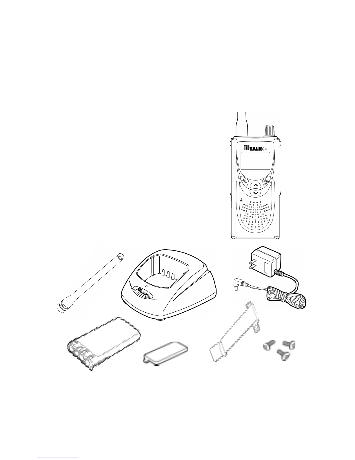
V. Unpacking and Checking Equipment
Carefully unpack the radio and its accessories. Use
the item list below to identify the components included
in the product packaging, to ensure that no items are
discarded in the packing materials.
Radio Body
Antenna
Battery Charger (with plastic spacer
stored in charger base)
AC Adapter
NiMH Battery Pack
Speaker Microphone Jack Cover
Belt Clip
Screw Set
Operating Instructions
If any items are missing or damaged, you should
contact the Topaz3 Customer Service Department
for assistance: 1-800-821-7848, Ext. 499.
5
6
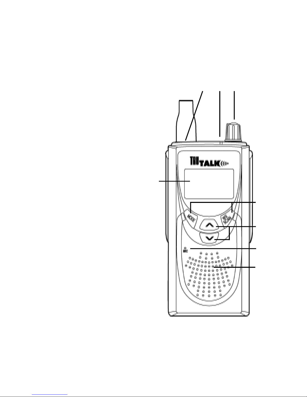
VI. Radio Control Buttons / Operation Features
A) Backlit LCD provides visual confirmation
of radio settings
B) Antenna Connector attaches the VHF antenna
C) LED Indicator identifies radio
status: transmit (red), receive
(signal only) orange,
(signal + CTCSS)
green, battery low
(flashing red)
D) Power / Volume Control
powers radio on and
adjusts radio volume
E) Mode Button
programs the
radio options
WX / Scan Button
selects the radio
weather frequencies
and starts the
scan function
F) Up / Down Buttons
selects various radio
options such as channel
number and beep tone
(on / off); scrolls through
radio programming options
G) Microphone
H) Speaker
B C D
E
F
G
H
A
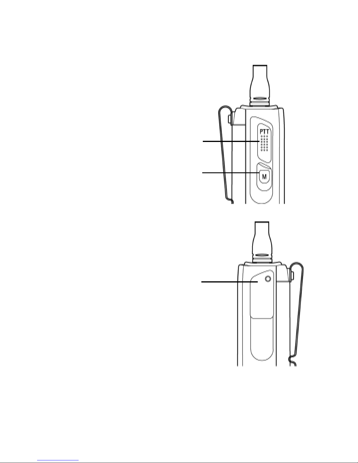
VI. Radio Control Buttons / Operation Features,
continued
LEFT SIDE OF RADIO
A) Push-To-Talk (P-T-T) Button
initiates radio transmissions
B) Monitor Button
monitors current channel
for activity; turns radio
squelch setting off
RIGHT SIDE OF RADIO
A) Speaker Microphone Jack
7
A
A
B
VI. Radio Control Buttons / Operation Features,
continued
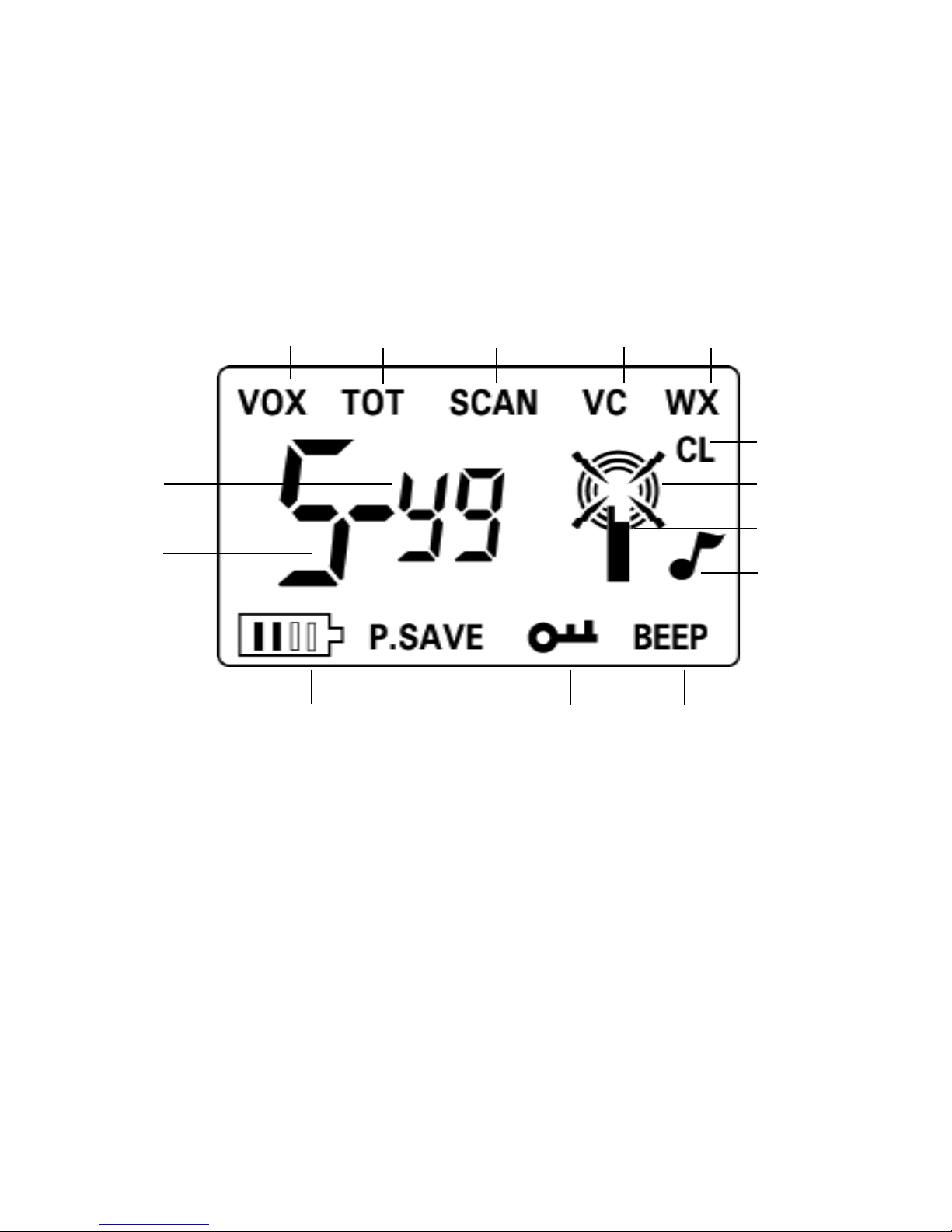
Backlit LCD Features
The MURS-25 has a large backlit Liquid Crystal Display
(LCD), which provides a quick visual confirmation of
the current radio settings.
A) VOX - Voice Activated Transmission Indicator shows
VOX operation is active, allowing hands-free transmissions
B) TOT - Time Out Timer Indicator shows transmit timer
mode is active, which prevents transmissions in excess
of 3 minutes
C) SCAN Indicator shows scan function is active
D) VC - Vacant Channel Scan Indicator shows unused
(vacant) channel search is active (used in conjunction
with the scan function)
8
M L K J
G
H
A B C D E
F
I
O
N

VI. Radio Control Buttons / Operation Features,
continued
Backlit LCD Features, continued
E) WX - Weather Receive Indicator shows that the radio is
in weather receive operation; flashing WX and SCAN
icons indicates that the weather scan function is active
F) CL - Carrier Lockout Indicator shows lockout of all radio
transmissions is active, allowing only radio reception
G) Radio Transmit (TX) or Receive (RX) Indicator
H) Radio Icon Indicator shows when radio is powered on
I)
- Talk Confirmation Tone Indicator shows "end of
transmission
" tone is active
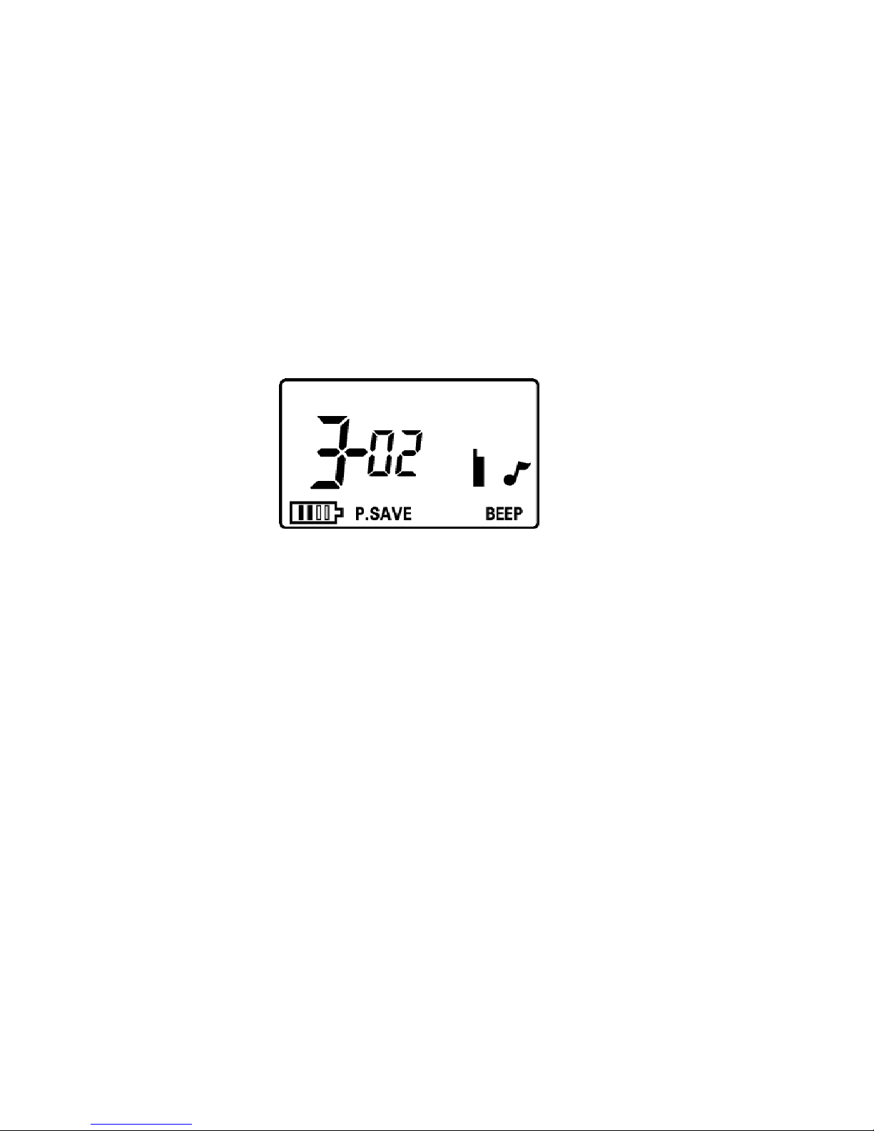
J) BEEP - Audible Tone Indicator shows
"beep" tone
function is active
K) - Function Lock Indicator shows front panel buttons
are in active
"lock" to prevent accidental channel change
or feature settings (the P-T-T and MONITOR buttons will
remain active)
L) P.SAVE - Power Save Indicator flashes when battery
power save feature is active
M) - Battery Level Indicator displays current battery
level; flashing icon indicates that a power failure is near
N) Main Channel Indicator shows current channel number
or other function indicators
O) Sub-Channel Indicator shows current CTCSS or DCS
tone code setting
9

10
VII. Getting Started
Charging the NiMH Battery Pack
You will need to charge the battery pack fully before
initial use. For best results from your charging cycle,
follow these tips:
• Ensure the ambient temperature is between 41 and
104° F (5 and 40° C) while charging. Temperatures
outside this range may not fully charge the battery.
• Always switch OFF the transceiver equipped with
a NiMH battery pack before charging. Using the
radio during the charging cycle will hinder correct
charging.
• Do not recharge the battery pack if it is already
fully charged. Doing so may cause the life of the
battery pack to shorten or the battery pack may
be damaged.
• If the battery is stored for 2 months or more, it is a
good idea to complete the charge / discharge cycle
two or three times to allow the battery capacity
to return to normal.
• Never dispose of the battery in fire - it can explode
causing personal injury.
• Never attempt to disassemble the battery or remove
its case material or charging contacts. Do not short
the battery terminals.

VII. Getting Started, continued
Charging the NiMH Battery Pack, continued
NOTE: The first few uses from the battery will not
be at normal capacity. After repeating the charge /
discharge cycle two or three times, the battery
capacity will increase to provide full capacity.
1. Plug the AC adapter cable in the adapter jack
located on the rear of the charger, then into
an AC outlet.
2. Slide the NiMH battery pack (or the radio
equipped with a NiMH battery pack) into the
charging slot.
3. Ensure that the metal contacts on the battery pack
come in contact with the charging terminals.
4. When charging the NiMH battery pack alone,
insert the provided plastic spacer (stored in
charger base) into the charging well, then insert
the battery pack.
5. The charger LED will light to advise that charging
has begun. Charge the standard battery pack for
9 hours. REMOVE THE PACK OR RADIO
FROM THE CHARGER.
IMPORTANT NOTE: The charger DOES NOT
TURN OFF AUTOMATICALLY after the charging
cycle has been completed. Damage to the battery
or reduced battery life may result if charged in
excess of the recommended charging time.
11

12
VII. Getting Started, continued
Attaching and Removing the Battery Pack
NOTE: After recharging the battery pack, REMOVE IT
FROM THE CHARGER.
The battery pack life is over when its operating time
decreases even though it is fully and correctly
charged. Replace the pack with the manufacturers
recommended model (TruTalk / Legacy ACC-203,
750 mAh or TruTalk / Legacy ACC-204, 1350 mAh).
Average battery pack life from the supplied 750 mAh
battery is 11+ hours; the optional 1350 mAh battery,
19+ hours. This service time is calculated using 90%
standby, 5% transmit and 5% receive time.
After charging the battery pack as described, you are
ready to install it to the radio body. Simply;
1. Match the four grooves of the battery pack with
the guides on the back of the radio.
2. Slide the battery pack up along the back of the
radio until the release latch locks.
To remove the battery pack, push down on the release
latch and slide the pack downward, and away from the
radio.

13
VII. Getting Started, continued
Installing the Antenna
Screw the antenna into the connector on the top of the
radio by holding the antenna at its base and turning
it clockwise until seated. Do not overtighten.
The antenna should never be used to carry your radio,
or as a base to clip radio accessories. Misuse of the
antenna can cause damage, and reduce your radios
performance.
Installing the Belt Clip
We recommend that the belt clip is installed on the
radio. It keeps the radio from coming in contact with
hot surfaces, and away from your body if heat build-up
occurs with excess transmissions.
Use the two supplied screws to install the belt clip. If
a replacement is needed, use a screw designed to the
exact specifications as the original, to prevent accidental contact with internal circuitry, or possible personal
injury. Never use glue in conjunction with the provided
screws. Some of the glues components may crack the
radio back panel, causing radio damage and possible
personal injury.
Installing the Speaker Microphone Jack Cover
If you are not using an accessory, install the provided
cover over the speaker microphone jack using the screw
supplied. This will keep the radio water resistant.

14
VII. Getting Started, continued
Attaching the Optional Speaker Microphone
1. Insert the speaker microphone jack into the radio.
2. Use the thumbscrew attachment on the speaker
microphone to make connection to the radio.
NOTE: The radio is not fully water resistant while the
speaker microphone is attached.

15
VIII. Radio Operation
Power On
Power on the radio by turning the power / volume
control clockwise out of detent. You will hear a
confirmation tone on power-up. To check radio
volume, press and hold the monitor button then
rotate the control to desired volume level.
The MURS-25 has two primary modes of operation:
1) Normal transmit and receive - This two-way radio
mode allows you to transmit and receive messages
with any other radio tuned to the same MURS
frequency as your radio.
2) Weather receive mode - This mode allows you to
listen to NOAA (National Oceanic and Atmospheric
Administration) weather broadcasts from the National
Weather Service. Refer to the "Weather (WX) Mode"
information in this manual for more information.

16
VIII. Radio Operation, continued
Normal Transmit and Receive
The MURS-25 is pre-programmed with the five (5)
Multi User Radio Service frequencies.
Select the channel that you wish to operate on, making
sure that all other radios you wish to communicate with
are on the same channel and CTCSS or DCS tone setting.
Refer to "Channel Frequency Selection" and "CTCSS /
DCS Tone Signaling" information in this manual for
more information.
Press the monitor button to check the channel for
activity. To avoid interrupting another use, make sure
the channel is clear before you begin transmitting.
To transmit, place the radio microphone approximately
2 (5 cm) from your mouth. Press and hold the P-T-T
bar while speaking in a normal tone. Release the P-T-T
bar when you are finished speaking; the radio will be
placed into receive mode.
When the battery pack voltage becomes too low for
operation to continue, the LED will blink red and a
tone will sound. The radio will allow only one more
transmission - change or charge your battery. Refer to
the "Low Battery Warning" section of this manual.
IX. Channel Frequency Selection
NOTE: Read all steps before attempting this process,
as the radio will exit the setup mode if keypresses are
not performed within 10 seconds.
Change the channel frequency by using these steps:
1. With the radio powered on, press the MODE button
one time or until the main channel indicator
flashes; activating the channel change mode.
2. Press the UP (
ÙÙ
ÙÙ
Ù) / DOWN (
ÚÚ
ÚÚ
Ú) buttons to select
the desired channel. See the "Factory Channel
Settings Table" below for frequency information.
3. To save the selected channel, press P-T-T button or
the WX / SCAN button. The radio will return to
normal receive mode.
Factory Channel Settings Table
Channel Frequency Band Width Default Transmit /
CTCSS / DCS Receive
1 151.8200MHz 11.25 kHz No Tone TX / RX
2 151.8800 11.25 kHz No Tone TX / RX
3 151.9400 11.25 kHz No Tone TX / RX
4 154.5700 12.5 kHz No Tone TX / RX
5 154.6000 12.5 kHz No Tone TX / RX
6 Repeater 12.5 kHz No Tone TX 154.6000
RX 154.5700
17

18
X. CTCSS / DCS Tone Signaling
CTCSS and DCS Tones prevent the radio from hearing
signals unless they match coded tones in your radio.
When a received signal has a code that matches your
code, squelch will open and you will hear the signal.
When a received signal has a code different from the
one set up in your radio, squelch will not open and
you will not hear the signal.
When you transmit on a channel set up with CTCSS
or DCS, the receiving radio must have a matching
code in order to hear your signal.
CTCSS Tones are selected from 38 standard and 11
non-standard tone signaling codes. Refer to the "CTCSS
and DCS Tone Signaling" tables on the following pages.
Change the CTCSS or DCS tone signaling format by
using these steps:
1. With the radio powered on, press the MODE button
two times or until the tone indicator begins to
flash to activate the CTCSS / DCS tone mode.
2. Press the UP (
ÙÙ
ÙÙ
Ù) or DOWN (
ÚÚ
ÚÚ
Ú) button to select
the desired format: OFF (factory default), CTCSS
or DCS.
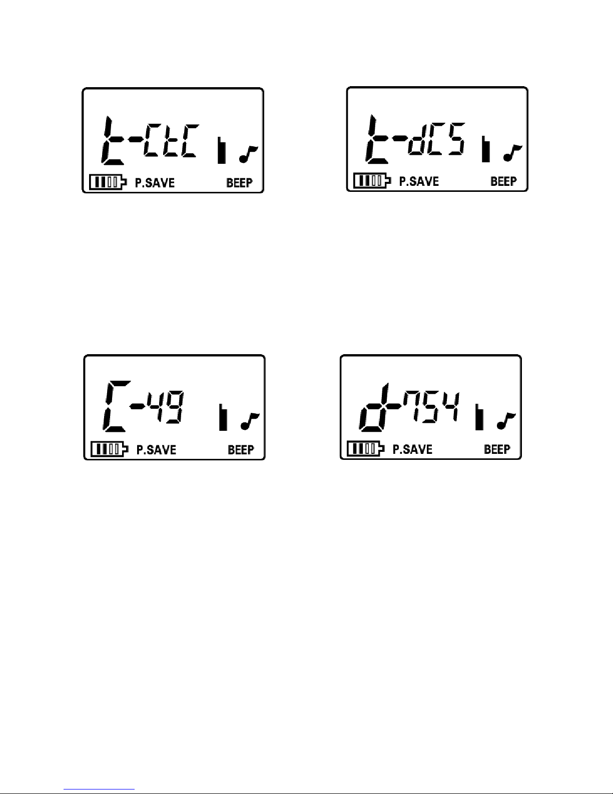
X. CTCSS / DCS Tone Signaling, continued
CTCSS Format Selection Screen DCS Format Selection Screen
3. Press the MODE button to enter the chosen format
and advance to the CTCSS or DCS code selection
display. Refer to the "CTCSS and DCS Tone
Signaling" tables on the following pages.
CTCSS Code Selection Screen DCS Code Selection Screen
4. Press the UP (
ÙÙ
ÙÙ
Ù) / DOWN (
ÚÚ
ÚÚ
Ú) buttons to select the
desired code for CTCSS or DCS tone signaling.
NOTE: All radios need to be set to the same
CTCSS or DCS code for proper transmitting /
receiving.
5. To continue with other programming functions,
press the MODE button. To save the selected
CTCSS or DCS tone settings, press the P-T-T or
WX / SCAN button and return to receive mode.
19

20
X. CTCSS / DCS Tone Signaling, continued
CTCSS Tone Signaling Table
All 38 TIA/EIA standard tone frequencies and 11 nonstandard tones will be accessible.
No. Freq. No. Freq. No. Freq. No. Freq.
01 67.0Hz 14 107.2Hz 27 167.9Hz 40 159.8Hz
02 71.9 15 110.9 28 173.8 41 171.3
03 74.4 16 114.8 29 179.9 42 177.3
04 77.0 17 118.8 30 186.2 43 183.5
05 79.7 18 123.0 31 192.8 44 189.9
06 82.5 19 127.3 32 203.5 45 196.6
07 85.4 20 131.8 33 210.7 46 199.5
08 88.5 21 136.5 34 218.1 47 206.5
09 91.5 22 141.3 35 225.7 48 229.1
10 94.8 23 146.2 36 233.6 49 254.1
11 97.4 24 151.4 37 241.8
12 100.0 25 156.7 38 250.3
13 103.5 26 162.2 39 69.3
NOTE: The 11 non-standard CTCSS tone codes are
shown in bold type in above table.

21
X. CTCSS / DCS Tone Signaling, continued
DCS Tone Signaling Table
All 104 TIA/EIA tone frequencies will be accessible.
Please note that these tone codes are not sequential.
DCS DCS DCS DCS DCS DCS DCS
Code Code Code Code Code Code Code
023 114 174 266 411 516 712
025 115 205 271 412 523 723
026 116 212 274 413 526 731
031 122 223 306 423 532 732
032 125 225 311 431 546 734
036 131 226 315 432 565 743
043 132 243 325 445 606 754
047 134 244 331 446 612
051 143 245 332 452 624
053 145 246 343 454 627
054 152 251 346 462 631
065 155 252 351 464 632
071 156 255 356 465 654
072 162 261 364 466 662
073 165 263 365 503 664
074 172 265 371 506 703

22
XI. Weather (WX) Mode
Select this function to listen to the local NOAA weather
broadcasts from the National Weather Service. These
broadcasts are receive-only, you cannot transmit on the
channel frequencies dedicated to weather.
1. With the radio powered on, press the WX / SCAN
button one time.
2. On the LCD, the main channel indicator will change
to show the current weather channel; the WX
icon appears to confirm the weather mode.
3. If the current channel setting is not receiving a
strong broadcast, you need to change the channel.
a)Press the MODE button to change the WX
channel selection, (the WX icon will display
and the current weather channel will flash).
b) Press the UP (
ÙÙ
ÙÙ
Ù) or DOWN (
ÚÚ
ÚÚ
Ú) button to
change to a channel receiving strong weather
broadcasts.
c)Press the P-T-T button to store the current WX
channel selection. Your radio will return to this
setting when you enter the WX mode again.
NOAA Weather Radio Frequency Table
Channel Frequency
1 162.5500 MHz
2 162.4000
3 162.4750
4 162.4250
5 162.4500
6 162.5000
7 162.5250
 Loading...