


.Trustwave.com Updated October 9, 2007
Secure Web Gateway
Version 11.5
Setup Guide

Secure Web Gateway 11.5 Setup Guide
Legal Notice
Copyright © 2013 Trustwave Holdings, Inc.
All rights reserved. This document is protected by copyright and any distribution, reproduction, copying,
or decompilation is strictly prohibited without the prior written consent of Trustwave. No part of this
document may be reproduced in any form or by any means without the prior written authorization of
Trustwave. While every precaution has been taken in the preparation of this document, Trustwave
assumes no responsibility for errors or omissions. This publication and features described herein are
subject to change without notice.
While the authors have used their best efforts in preparing this document, they make no representation
or warranties with respect to the accuracy or completeness of the contents of this document and
specifically disclaim any implied warranties of merchantability or fitness for a particular purpose. No
warranty may be created or extended by sales representatives or written sales materials. The advice and
strategies contained herein may not be suitable for your situation. You should consult with a professional
where appropriate. Neither the author nor Trustwave shall be liable for any loss of profit or any
commercial damages, including but not limited to direct, indirect, special, incidental, consequential, or
other damages.
The most current version of this document may be obtained by contacting:
Trustwave Technical Support:
Phone: +1.800.363.1621
Email: support@Trustwave.com
Trademarks
Trustwave and the Trustwave logo are trademarks of Trustwave. Such trademarks shall not be used,
copied, or disseminated in any manner without the prior written permission of Trustwave.
Revision History
Version Date Changes
1.0 February 2012 Version 10.2
2.0 October 2012 Version 11.0 update
2.1 November 2013 Version 11.5 update
Copyright © 2013 Trustwave Holdings, Inc. All rights reserved. ii

Secure Web Gateway 11.5 Setup Guide
Formatting Conventions
This guide uses the following formatting conventions to denote specific information.
Formats and Symbols Meaning
Blue Underline A blue underline indicates a Web site or email address.
Bold Bold text denotes UI control and names such as commands, menu items, tab and field
names, button and check box names, window and dialog box names, and areas of
windows or dialog boxes.
Code
Italics
[Square brackets] Square brackets indicate a placeholder for values and expressions.
Text in Lucinda Console indicates computer code or information at a command
line.
Italics denotes the name of a published work, the current document, name of another
document, text emphasis, or to introduce a new term.
Notes, Tips, and Warnings
Note: This symbol indicates information that applies to the task at hand.
Tip: This symbol denotes a suggestion for a better or more productive way to use the
product.
Caution: This symbol highlights a warning against using the software in an unintended
manner.
Question: This symbol indicates a question that the reader should consider.
Copyright © 2013 Trustwave Holdings, Inc. All rights reserved. iii

Secure Web Gateway 11.5 Setup Guide
Table of Contents
Legal Notice ii
Trademarks ............................................................................................................................... ii
Revision History ......................................................................................................................... ii
Formatting Conventions iii
Notes, Tips, and Warnings ........................................................................................................ iii
About This Guide v
1 Before You Begin 6
2 Installing the Appliance 6
2.1 Installing a Physical SWG Appliance .................................................................................. 6
2.1.1 Requirements before Installing a Physical Appliance ............................................... 7
2.1.2 Connecting an Appliance Using an Ethernet Cable .................................................. 7
2.1.2.1 For SWG 3000 and SWG 5000 models: ................................................ 7
2.1.2.2 For an SWG 7000 appliance: ............................................................... 8
2.1.3 Connecting an Appliance Using a Serial Cable ........................................................ 9
2.2 Deploying a Virtual SWG from an OVF File ......................................................................... 9
3 Setting Up the Appliance 10
3.1 Preparing Values for the Appliance Setup ........................................................................ 10
3.2 Setting Up the Appliance ................................................................................................ 11
4 Performing Additional Configuration 12
4.1 Limited Shell Commands — Summary List ....................................................................... 12
4.2 Limited Shell Configuration Commands ............................................................................ 14
4.3 Limited Shell Monitoring Commands ................................................................................ 18
5 SWG Installation Utility 22
5.1 Usage Instructions ......................................................................................................... 22
5.1.1 Upgrading the Policy Server and All-in-One .......................................................... 23
5.1.2 Scanning Servers Upgrade .................................................................................. 24
5.1.3 Using the USB Key ............................................................................................. 24
5.1.4 Using the config_upgrade Command ................................................................... 24
5.2 Limited Shell .................................................................................................................. 25
Copyright © 2013 Trustwave Holdings, Inc. All rights reserved. iv

Secure Web Gateway 11.5 Setup Guide
6 Upgrading from Version 10.2 26
7 USB Key Creator 27
7.1 Notes and Warnings ....................................................................................................... 27
7.2 Usage Instructions ......................................................................................................... 27
About This Guide
This guide provides the instructions you need to install and set up your Trustwave SWG appliance.
Copyright © 2013 Trustwave Holdings, Inc. All rights reserved. v

Secure Web Gateway 11.5 Setup Guide
1 Before You Begin
Note: Physical SWG appliances come with the required image already loaded. Should you need to reload
or replace the image, refer to SWG Installation Utility on page 22.
You should perform the following tasks in the order listed:
1. Installing the Appliance
2. Setting Up the Appliance
3. Performing Additional Configuration
After you have set up the appliance, you can configure the system according to your needs. For
instructions, see the
Management Console Reference Guide
.
2 Installing the Appliance
This section contains the following:
• Installing a Physical SWG Appliance
• Deploying a Virtual SWG from an OVF File
2.1 Installing a Physical SWG Appliance
Installation consists of connecting to the appliance. You can connect in any of the following ways:
• Using an Ethernet cable
• Using a Serial cable (SWG 3000 and SWG 5000 only)
• Using a keyboard and monitor
Instructions for connecting are provided on the following pages. Before connecting to the appliance,
ensure that the following requirements are satisfied.
Copyright © 2013 Trustwave Holdings, Inc. All rights reserved. 6

Secure Web Gateway 11.5 Setup Guide
2.1.1 Requirements before Installing a Physical Appliance
• Working electrical outlet:
• 1 x Outlet for the SWG 3000
• 2 x Outlets for the SWG 5000
• 4 x 16amp Outlets for the SWG 7000, preferably via PDU
• Network connection — cable and switch
• Hardware for connecting — ethernet cable, serial cable, or a keyboard and monitor
• Rack space for the appliance
• 1U Rack space for SWG 3000 or SWG 5000
• 7U Rack space for SWG 7000
• Switch port for the internet cable
• Appliance name
• Physical address
• DNS address
• DNS name
• Default gateway
2.1.2 Connecting an Appliance Using an Ethernet Cable
2.1.2.1 For SWG 3000 and SWG 5000 models:
1. Plug in the power cable and switch the appliance on.
2. Connect a PC directly to the appliance’s GE0 port or via a switch (for 5000-SWG, see 5000-SWG Rear
Panel) using a standard (8 thread) Ethernet cable. CAT5e cables (or better) are recommended.
3. The default IP of the GE0 interface is 10.0.0.1, and its default netmask is 255.255.255.0. Configure
the TCP/IP settings of your PC so that it is on the same logical network subnet as the appliance’s GE0
interface. For example, configure the IP on the PC as 10.0.0.101 and the PC’s netmask as
255.255.255.0.
IMPORTANT: Do not set the PC’s IP to 10.0.0.1, as this will result in an IP conflict with the appliance.
4. Continue with initial setup of your SWG Appliance using Limited Shell.
Copyright © 2013 Trustwave Holdings, Inc. All rights reserved. 7

Secure Web Gateway 11.5 Setup Guide
2.1.2.2 For an SWG 7000 appliance:
The SWG 7000 model is a chassis containing blade servers, each of which operates as an appliance. This
provides for overall higher end performance.
Perform the following procedure for each blade regardless of its intended network role.
1. Plug in the power cables.
2. Configure the network settings of any PC to match those of the appliance (IP address and subnet
mask).
• IP address in the same subnet e.g. 10.0.0.101
• Subnet mask 255.255.255.0
3. Connect your PC to one of the ports on the Gigabit Ethernet switch in I/O switch module Bay 1 on
the appliance using an ethernet cable.
4. Power up the blades as follows:
In the control panel for the blade:
a. Press the KVM Select button so that the VGA screen attached to the chassis displays output from
the blade being powered up.
b. Press the Power button until the blade turns on. After the blade finishes booting, a login prompt
is displayed.
5. Continue by doing either of the following:
• Repeat Step 1 for each blade, and when done, continue with initial setup of your SWG Appliance
blades using the Limited Shell, or
• Continue with initial setup of this SWG Appliance blade using the Limited Shell, and when done,
repeat Step 1 for each blade.
Note: For more information on setting up the SWG 7000, contact your Trustwave representative.
Copyright © 2013 Trustwave Holdings, Inc. All rights reserved. 8

Secure Web Gateway 11.5 Setup Guide
2.1.3 Connecting an Appliance Using a Serial Cable
Note: Connection using a serial cable is applicable only to SWG 3000 and SWG 5000 appliances.
1. Connect the PC to the appliance’s Serial Console, using the serial cable.
2. Using the Hyper Terminal application, enter the appropriate Port settings:
• Bits per Second (Baud Rate): 19,200
• Data Bits (Word): 8
• Parity: None
• Stop bits: 1
2.2 Deploying a Virtual SWG from an OVF File
This section explains how to deploy a virtual SWG from an OVF file. Virtual SWG appliances are certified
to work with VMWare ESXI version 4.1 servers.
Note: Before deploying the virtual appliance, ensure that you have access to a VMWare vSphere client
and that the OVF files are accessible in your local machine.
1. In the vSphere client, choose File | Deploy OVF Template.
2. In the wizard, browse to the OVF file and then complete the deployment.
When done, it is recommended that you set the attributes for the virtual machine according to the values
in the following table.
Machine Attribute Recommended Value
CPUs At least 2
Memory At least 4GB
Copyright © 2013 Trustwave Holdings, Inc. All rights reserved. 9

Secure Web Gateway 11.5 Setup Guide
3 Setting Up the Appliance
The setup procedure is the same for both physical and virtual SWG appliances. You perform the setup
using a setup script that is run in the Limited Shell.
Note: Before setting up the installed appliance, you should prepare for setup by assembling the detailed
This section contains the following:
• Preparing Values for the Appliance Setup
• Setting Up the Appliance
3.1 Preparing Values for the Appliance Setup
What to Do Details
information and values that you will need to supply as part of setup.
1 Decide the role of the
appliance
2 Decide which network
interface should be used
for the appliance:
Network Interfaces Description
GE0 (eth0): 1GB - Autonegotiation enabled Recommended!
You must define a single Policy Server (provides management and reporting
services), and at least one Scanner (provides scanning and authentication
services). You can choose to define both of these roles in the same appliance
or in different appliances:
• All In One (Default) – Defines the appliance as both a Policy Server
and a Scanner. This value is often used for SWG 3000 or 5000 models.
• SWG Scanner – Defines the appliance or blade as a Scanner only.
• SWG Policy Server – Defines the appliance or blade as a Policy Server
only.
• Standby Policy Server – Defines the appliance as a standby Policy
Server to support high availability.
Allows communication at a speed of up to 1GB with Auto-Negotiation
enabled. Auto- negotiation enables simple, automatic connection of appliances
by taking control of the cable when a connection is established to a network
device that supports a variety of modes from a variety of manufacturers. The
device is able to automatically configure the highest speed.
GE1 (eth1): 1GB - Auto-
negotiation
Copyright © 2013 Trustwave Holdings, Inc. All rights reserved. 10
Allows communication at a speed of up to 1GB with Auto-Negotiation
enabled.

Secure Web Gateway 11.5 Setup Guide
What to Do Details
GE2 (eth2): 1GB - Auto-
negotiation
GE3 (eth3) 1GB - Auto-
negotiation
3 Determine the IP address and netmask for the selected interface as IP/ (netmask/prefix), if you will not be using
the default settings.
4 Determine the Default Gateway IP address.
5 Determine the hostname if you will not be accepting the current settings.
6 Determine the IP address for the DNS Server if you will not be accepting the current DNS configuration settings.
Note: DNS configuration setting is mandatory.
7 Determine the DNS domain names if you will not be accepting the current settings.
8 Decide on any password changes if required.
(Available for SWG 5000, and the Policy Server in SWG 7000 only.) Allows
communication at a speed of up to 1GB with Auto-Negotiation enabled.
(Available for SWG 5000, and the Policy Server in SWG 7000 only.) Allows
communication at a speed of up to 1GB with Auto-Negotiation enabled.
3.2 Setting Up the Appliance
Perform the setup using the values you prepared.
1. Log in to the Limited Shell. The default user name and password for the shell (command line) is
admin and TrustwaveSWG respectively:
• For a physical machine, you can connect from a remote machine using an SSH client, serial
cable, or by connecting a keyboard and monitor to the appliance.
• For a virtual appliance, connect through the vSphere client.
2. Enter the setup command. The current configuration status is displayed.
3. Using the data you prepared, page through the setup script entering the needed values. This
displayed configuration is updated as you enter values.
Copyright © 2013 Trustwave Holdings, Inc. All rights reserved. 11

Secure Web Gateway 11.5 Setup Guide
4 Performing Additional Configuration
You can optionally use the commands of the Limited Shell to manage the functionality and monitor the
appliance.
Each appliance has different configuration needs, so there is no set procedure. Enter the relevant Limited
Shell commands and values.
Limited Shell commands are divided into two categories; Configuration commands and Monitoring
commands.
This section contains the following:
• Limited Shell Commands — Summary List
• Limited Shell Configuration Commands
• Limited Shell Monitoring Commands
4.1 Limited Shell Commands — Summary List
The following monitoring and configuration commands are available:
Note: The A/C/M column indicates if the command is an Administration (A), Configuration(C), or
For more information on configuring the system, refer to Limited Shell Configuration Commands.
For further in-depth analysis and diagnostics of the system, refer to Limited Shell Monitoring Commands.
Command
access_list
arp
change_password
check_connectivity
config_ ...
Monitoring (M) command.
A/C/M
C
Enables/disables access list
M
Displays the arp table
C
Change password
M
Checks connectivity to the remote devices (for Policy Server or All-
C
Description
in-One appliances)
Network or service configuration. Double tab to view the
config_network, config_time, config_hardware,
config_upgrade, config_support, config_psweb,
config_exclude, config_bridge, and config_access_log
commands.
Copyright © 2013 Trustwave Holdings, Inc. All rights reserved. 12

Secure Web Gateway 11.5 Setup Guide
Command
df
disable_ ...
enable_ ...
ethconf
flush_dnscache
ifconfig
ip2name
iptraf
last
name2ip
A/C/M
M
Displays disk usage
C
Disables service. Double tab to view the
C
C
Menu interface to ethtool
C
Flushes the DNS cache
M
Displays NIC configuration and statistics
M
Resolves IP to hostname
M
Interactive IP LAN monitor
M
Displays last login
M
Resolves hostname to IP
Description
disable_service_snmpd
Enables service. Double tab to view the enable_service_snmpd
and enable_service_ssh
and disable_service_ssh
commands.
commands.
netstat
ping
poweroff
reboot
reset_config
restart_role
save_exclude_logs
save_support_logs
setup
show_ ...
M
Displays Network statistics
M
Sends ICMP ECHO_REQUES to network hosts
A
Powers off the system
A
Reboots the system
C
Sends full configuration to appliance
A
Restarts the role
M
Saves Exclude logs
M
Saves Support logs
C Runs configuration setup
M
Shows system or service status. Double tab to view the
show_bridge, show_config, show_hardware,
show_network
, show_service, show_dbsize,
show_proxy_buffers, show_proxy_connections,
show_route
, show_time, and show_version commands.
A
supersh
Copyright © 2013 Trustwave Holdings, Inc. All rights reserved. 13
Provides access to privileged shell

Secure Web Gateway 11.5 Setup Guide
access_list
change_password
Command
tcpdump
top
traceroute
uptime
vmstat
w
wget
A/C/M
M
Dumps traffic on a network. Results files will be under sftp chroot/
M
Displays Linux tasks
M
Prints the route packets taken to network host (traceroute
M
Displays uptime
M
Reports information about system usage (usage: vmstat,
M
Shows who is logged on
M
Retrieves files using HTTP, HTTPS and FTP
Description
tcpdump_captures. Files can be downloaded using any sftp client
4.2 Limited Shell Configuration Commands
Limited Shell configuration commands enable you to define the role the appliance takes, the security,
access and time settings, and also carry out routine maintenance operations. The configuration
commands are also used to define how the network works, and how the appliance communicates with
the network.
This feature is configured from the Management Console. The administrator can define a range of IP
addresses to access Management applications on predefined ports (such as the Management Console,
SNMP, SSH) or User applications on predefined ports (such as HTTP, FTP, ICAP) or System ports (internal
ports). Any IP address not defined in the IP range will then be blocked from accessing these applications
on the ports defined by Trustwave.
The access_list command is used to enable or disable the Access List and is useful for situations when
due to a mistaken configuration, or other circumstances, you cannot access the Management Console,
and want to disable the Access List feature.
Enter the access_list command and choose enable or disable.
Allows system administrators to change the Limited Shell’s password. For security reasons, it is
recommended to choose a password which contains both characters (higher case and lower case) and
digits. It is also recommended to change the password frequently.
Enter the change_password command and confirm current and new passwords.
Copyright © 2013 Trustwave Holdings, Inc. All rights reserved. 14

Secure Web Gateway 11.5 Setup Guide
config_ ...
config_network
config_time
Enables network, service and Policy Server configuration. Press the tab button twice to display the
config_network, config_time, config_hardware, config_upgrade, config_support, config_psweb,
config_exclude, config_bridge, and config_access_log commands.
Allows system administrators to configure network parameters, such as the IP address(es), routing
information, DNS parameters. Enter the config_network command.
The current network configuration is displayed (i.e. the DNS Search Domain, nameserver and Hostname
configuration). A Name Server is a network server that provides a naming or directory service. A prompt
is displayed asking if you want to change the configuration. Enter y to change the network configuration.
Select an option from the following commands:
• View: This command allows you to view the current network configuration: The IP address assigned
to each interface, the current DNS configuration and the current hostname configuration.
• Interface: Allows system administrators to modify interface related parameters such as: Add,
Remove or Change an IP address from a physical interface; Add, Remove or Change routing
information; Enable or Disable a physical interface.
• Choose an interface, for example, 1 (eth0). The editing options are displayed.
• Choose an editing action, for example, 1 (Change IP address). To add a static route, choose 4
(Add route). The new route must be input as ‘IP/via prefix IP’. For example, 1.1.1.1/32 via 10.0.3
• Gateway: Allows system administrators to set the default gateway of the appliance. The IP address
of the default gateway must be a local IP address. It is mandatory to configure a default gateway to
the appliance. To change the current gateway configuration, enter the IP address.
• DNS: Allows configuring the DNS servers, which the appliance uses in order to resolve the
hostnames to IP addresses. It is also possible to configure a search domain under the DNS settings
which allows the appliance to complete the domain name (according to the configured value) in case
the host name is not completed. For example, if the search is on http://mize and the search domain
is Trustwave.com, the appliance will try to resolve to http://mize.Trustwave.com.
IMPORTANT: It is mandatory to configure the DNS Server that has the ability to resolve external IP
addresses
The current DNS configuration is displayed. Select an action, for example, 1 (change search).
• Hostname: Allows configuring the appliance hostname.
• Hosts: Allows configuring the host files.
Allows system administrators to set the system date and time, the time zone and also the NTP Server. To
change a setting, type y. Select an option from the menu, else Q to exit.
Copyright © 2013 Trustwave Holdings, Inc. All rights reserved. 15

Secure Web Gateway 11.5 Setup Guide
config_hardware
config_upgrade
config_support
config_psweb
config_exclude
config_bridge
config_access_log
disable_ ...
This command allows the system administrator to configure an installed Caching Kit and/or Bypass NIC.
Note: Caching Kit is relevant to both physical and virtual devices. Bypass NIC is relevant only to physical
devices.
When the command is entered, the screen displays the installation and configuration status of these two
pieces of hardware.
To configure an installed piece of hardware, select the hardware option (Caching Kit or Bypass NIC)
from the menu, and then enter Y to configure it. Select Q to exit.
After upgrading the Policy Server to a new version, running this command will upgrade the scanners.
Allows you to install support packages.
Allows you to change the Policy Server management port for enhanced security. To change the Listening
port for the Policy Server, add the new Port settings.
Defines bypass rules in intercepting proxy mode.
Configures intercepting proxy to work in bridge mode. In Bridge mode, only traffic that should be
scanned will be processed. All other traffic will flow uninterrupted.
Enables or disables the access log.
Disables the service. The disable command includes the disable_service_snmpd and disable_service_ssh
commands.
Copyright © 2013 Trustwave Holdings, Inc. All rights reserved. 16

Secure Web Gateway 11.5 Setup Guide
disable_service_snmpd
disable_service_ssh
enable_ ...
enable_service_snmpd
enable_service_ssh
ethconf
flush_dnscache
reset_config
Disables the snmpd network service. Enter the disable_service_snmpd command.
Disables the ssh network service. Enter the disable_service_ssh command.
Enables the network service. The enable command includes the enable_service_snmpd and
enable_service_ssh commands.
Enables the snmpd network service. Enter the enable_service_snmpd command.
Enables the ssh network service. Enter the enable_service_ssh command.
Enables configuring the Network Interface parameters.
Enter the ethconf command and choose the required interface. Choose the required speed or select Autonegotiation to enable the appliance to negotiate its own speed.
Enter the ethconf command and choose the interface, for example, enter 1 (eth1).
The settings for the selected interface are displayed.
Choose configuration for the adapter and confirm to make the settings permanent
Note: According to the IEEE 802.3 standard, when working with 1000Base-T at a speed of 1000Mbps,
auto-negotiation must be enabled. A fixed speed of 1000Mbps is not supported. For more information,
refer to the 1000BASE-X Auto-Negotiation standard as defined in Clause 37 of the IEEE 802.3 standard.
Flushes the dns cache.
Rebuilds the appliance configuration in extreme situations where the appliance, for whatever reason, was
disconnected for a period of time. This action restarts the appliances and may take several minutes.
Copyright © 2013 Trustwave Holdings, Inc. All rights reserved. 17

Secure Web Gateway 11.5 Setup Guide
arp
check_connectivity
df
ifconfig
ip2name
iptraf
4.3 Limited Shell Monitoring Commands
Address Resolution Protocol command — the standard method for finding a host's hardware address
when only its network layer address is known. Enter the arp command to display the appliance's arp
table.
For Policy Server or All-in-One appliance, checks connectivity to the remote devices.
Disk free command — a standard Unix command used to display the amount of available disk space for
file systems.
Enter the df command to display the disk usage.
This Unix command is used to display TCP/IP network interfaces. Enter the ifconfig command to display
configuration and statistics.
Looks up the hostname associated with an IP address entered by the administrator. Enter the ip2name
command followed by the IP address to display the associated hostname.
This command is a Linux network statistics utility. It gathers a variety of parameters such as TCP
connection packet and byte counts, interface statistics and activity indicators, TCP/ UDP traffic
breakdowns, and LAN station packet and byte counts. Enter the iptraf command to display the IP traf
options:
• IP traffic monitor
• General Interface Statistics
• Detailed Interface Statistics
• Statistical breakdowns
• LAN station monitor
For example, select IP traffic monitor to display the IP traffic monitor details.
Copyright © 2013 Trustwave Holdings, Inc. All rights reserved. 18

Secure Web Gateway 11.5 Setup Guide
last
name2ip
netstat
ping
poweroff
reboot
restart_role
save_exclude_logs
save_support_logs
Displays a list of the previous administrators who logged on to the Limited Shell - including those still
logged on.
Displays the IP address associated with a given hostname. Enter the name2ip command followed by a
hostname to display the associated IP address.
This command is a useful tool for checking your network configuration and activity. It displays the status
of network connections on either TCP, UDP, RAW or UNIX sockets to the system.
Use the ping command to check the network connectivity - for example after using netconf.
Enables you to remotely shut down the appliance.
IMPORTANT: Physical access to the appliance is needed to bring the system back online for all models
except the 7000-SWG.
Enables you to remotely reboot the appliance.
Restarts all role services.
Saves Exclude logs in the Exclude directory.
Saves Support logs in the Support directory.
Copyright © 2013 Trustwave Holdings, Inc. All rights reserved. 19

Secure Web Gateway 11.5 Setup Guide
setup
show_ ...
show_bridge
show_config
show_hardware
show_network
show_service
show_dbsize
show_proxy_buffers
Assists you in setting up the appliance for the first time. It guides you to perform all the necessary steps
to establish a working appliance. You can choose to rerun the setup command to repeat the initial
configuration commands at any time.
Shows system or service status. The show command includes show_bridge, show_config, show_network,
show_service, show_dbsize, show_proxy_buffers, show_proxy_connections, show_route, show_time, and
show_version.
Shows the Bridge role configuration.
Shows the current configuration.
Shows the hardware specs of a given SWG device.
Shows the current network configuration. This includes: defined interfaces, DNS configuration, DNS cache
and current hostname.
Allows system administrators to view the service configuration status.
The following options are available:
• show_service_all: Displays the service configuration status for all the available services.
• show_service_snmpd: Displays the service configuration status for snmpd.
• show_service_ssh: Displays the service configuration status for ssh.
Shows the file size of the data- bases connected with your appliance.
Shows the status of proxy buffers.
Copyright © 2013 Trustwave Holdings, Inc. All rights reserved. 20

Secure Web Gateway 11.5 Setup Guide
show_proxy_connections
show_route
show_time
show_version
supersh
tcpdump
traceroute
uptime
Shows the status of proxy connections.
Allows system administrators to view the Kernel IP routing table.
Allows system administrators to view the time, date, time zone and ntp settings.
Shows the currently installed SWG version.
Enables root access to the appliance. This command is reserved for Trustwave Support only.
Allows the user to intercept and display TCP/IP and other packets being transmitted or received over a
network to which the computer is attached. It writes all the information into a tcpdump file. This file can
then be downloaded for further analysis. Up to 4 files of 100 MB each are kept. When the fourth file gets
full, the first file is deleted (i.e.cyclic progression). SFTP, such as WinSCP, is required in order to
download the files.
top
Displays all the running processes, and updates the display every few seconds, so that you can
interactively see what the appliance is doing.
Displays the route over the network between two systems, listing all the intermediate routers a
connection must pass through to get to its destination. It can help you determine why connections to a
given server might be poor, and can often help you figure out where exactly the problem is.
Produces a single line of output that shows the current time, how long the system has been running (in
minutes) since it was booted up, how many user sessions are currently open and the load averages.
Copyright © 2013 Trustwave Holdings, Inc. All rights reserved. 21

Secure Web Gateway 11.5 Setup Guide
vmstat
w
wget
Reports statistics about kernel threads, virtual memory, disks, traps and CPU activity. Reports generated
by the vmstat command can be used to balance system load activity.
Shows who is currently logged on and the current command they are running.
Allows you to download web files using HTTP, HTTPS and FTP protocols.
5 SWG Installation Utility
The SWG Installation Utility replaces the previous version upgrade mechanism as of version 9.0. The
Installation Utility provides several options for version upgrades and clean installations.
The SWG Installation Utility should be used in the following scenarios:
• Upgrade to any currently available version, starting from version 10.1
• Clean installation of last version
• Restoration of previous versions
If upgrading from Version 10.2 to Version 11.x or later, go to Upgrading from Version 10.2 on page
26.
5.1 Usage Instructions
Notes:
• The SWG Installation Utility is an application provided by Trustwave. To use the application it must
be placed on a bootable USB key with the relevant version ISO files. If you have not yet configured a
bootable USB key, refer to USB Key Creator on page 26.
(The necessary files for the USB key installation are found in the Support section of the Trustwave
website.)
• Physical access to the Policy Server is required to connect the USB key.
Copyright © 2013 Trustwave Holdings, Inc. All rights reserved. 22

Secure Web Gateway 11.5 Setup Guide
5.1.1 Upgrading the Policy Server and All-in-One
To upgrade the Policy Server:
1. Connect the USB key to the Policy Server and reboot the appliance.
Note: Ensure that the appliance boots from the USB as the first boot device.
After the appliance boots from the USB key, the following options are displayed.
(The menu is dynamic and therefore this image is for example purposes only):
2. Select the required option.
Note: After the upgrade option is selected, the current system is automatically backed up. The system
verifies which ISO files are available on the USB key for use.
The menu displayed is based on the ISO files available on the USB and HDD/image partition.
Therefore, the list is dynamic. The following is a sample menu:
The format of the filenames is designed so that the first *** numbers displayed are the version
number, and the subsequent b** is the build number.
Copyright © 2013 Trustwave Holdings, Inc. All rights reserved. 23

Secure Web Gateway 11.5 Setup Guide
3. Select the required option.
The following menu opens:
Note: The above clean installation option differs from the main menu clean install in that it keeps all
(saved) device settings and ISO images intact.
4. To continue the upgrade, select option 1.
The system will now install a fresh installation on the Policy Server and restore the previous settings
on the device (Network, GUI Configuration, Logs and Reports).
5.1.2 Scanning Servers Upgrade
After the upgrade utility has completed upgrading the Policy Server, the remote devices (if present) must
also be upgraded.
The following options are available:
5.1.3 Using the USB Key
To upgrade the scanning servers follow the procedure described in Upgrading the Policy Server and
All-in-One on page 23. This process requires physical access to all scanning servers and cannot be
performed remotely.
5.1.4 Using the config_upgrade Command
The config_upgrade command (available on the Policy Server starting with version 9.2 only when
upgraded from 9.0 M02 and up) allows you to decide which groups of remote devices to upgrade and in
what order.
Note: Scanners can be divided into specialized ‘groups’, which enables upgrading for specific devices
only.
Copyright © 2013 Trustwave Holdings, Inc. All rights reserved. 24

Secure Web Gateway 11.5 Setup Guide
5.2 Limited Shell
The following steps are required to upgrade the remote devices using the config_upgrade command
from the limited shell.
These procedures describe the upgrade process using an All-in-One appliance (Policy Server and
Scanner) with an additional remote scanning server.
1. Log in to the limited shell of the upgraded Policy Server.
2. Run config_upgrade.
3. The list of available scanners is displayed. Press Y.
4. New upgrade group. Enter 1.
5. The scanner is listed under Group 1. Press N when prompted to change the configuration. This will
start the upgrade process.
6. Start the Upgrade: Press Y.
Copyright © 2013 Trustwave Holdings, Inc. All rights reserved. 25
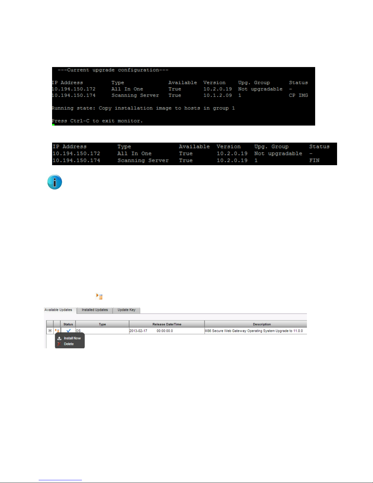
The status of the installation is displayed under Running State.
For example, “Copy installation image to hosts in group 1”.
The installation is complete. The new version is installed on the scanner.
Note: If there are additional groups, the system will automatically move to the next upgrade group.
Groups that have already been upgraded will not change.
Secure Web Gateway 11.5 Setup Guide
6 Upgrading from Version 10.2
With the introduction of version 11, upgrading the SWG has been simplified and can now be done from
the GUI (Administration | Updates and Upgrades | Management).
To upgrade the Policy Server to Version 11:
When running version 10.2, the OS update will display in the Available Updates tab.
1. Right-click the icon on the left and select Install Now.
Copyright © 2013 Trustwave Holdings, Inc. All rights reserved. 26

Secure Web Gateway 11.5 Setup Guide
After the upgrade is complete and GUI access is restored, the scanners can be upgraded from the
Trustwave devices tree.
2. Navigate to Administration | System Settings | SWG Devices.
3. Right-click the Scanning Server IP and selecting Upgrade to PS Version.
You can also downgrade from the current version by selecting Downgrade to Previous Version.
7 USB Key Creator
This section describes the bootable USB key creator procedure for re-imaging or upgrading the Secure
Web Gateway.
• The USB Key Creator is certified for Windows XP Service Pack 2 and later.
• Any residual instances of “VS Installer” in filenames or utility names refer to the SWG Installation
Utility.
7.1 Notes and Warnings
• The installation of files onto the bootable USB is not required in a specific sequential order when
copying SWG Installation Utility files manually.
• Ensure that the latest SWG Installation Utility is used, as it is compatible with previous versions and
older hardware.
• The USB Creator will format the USB drive and all previous data will be deleted.
7.2 Usage Instructions
To download and install files:
1. Navigate to the Trustwave Support section of the Trustwave website. Proceed to the SWG Downloads
and Documentation section/Product Downloads.
2. Log in with valid email and password credentials.
3. Download the USB Creator for Windows. The file is titled Trustwave_Disk-on-Key.zip and includes the
TrustwaveUSB.exe and TrustwaveUSBTOOL.avi files.)
Copyright © 2013 Trustwave Holdings, Inc. All rights reserved. 27

Secure Web Gateway 11.5 Setup Guide
4. Create a working directory, unzip the files, and run SETUP to install the program.
5. From the Trustwave Support website section, copy the SWG Installation Utility files and the ISO into
the working directory.
6. Unzip the SWG Installation Utility files to the working directory.
7. Insert a USB key and run the USB Key Creator program from its saved location.
8. Choose the USB key drive letter and browse to the working directory.
Make sure that you have selected the correct drive letter!
9. Click CREATE for the program to format the USB key and copy the necessary files.
10. When complete, the USB key is ready to use for the SWG Installation/upgrade. For more information,
refer to SWG Installation Utility on page 22.
Copyright © 2013 Trustwave Holdings, Inc. All rights reserved. 28

About Trustwave®
Trustwave is a leading provider of compliance, Web, application, network and data security solutions
delivered through the cloud, managed security services, software and appliances. For organizations faced
with today's challenging data security and compliance environment, Trustwave provides a unique
approach with comprehensive solutions that include its TrustKeeper® portal and other proprietary
security solutions. Trustwave has helped hundreds of thousands of organizations — ranging from Fortune
500 businesses and large financial institutions to small and medium-sized retailers — manage compliance
and secure their network infrastructures, data communications and critical information assets. Trustwave
is headquartered in Chicago with offices worldwide. For more information, visit
https://www.trustwave.com
.
 Loading...