

Page 1
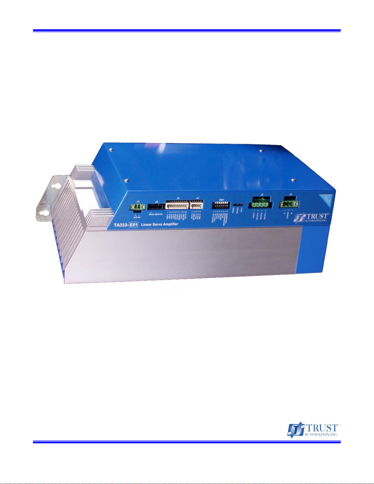
Trust Automation, Inc. TA333 High Power Linear Drive
TA333
High Power Linear Servo Amplifier
PRELIMINARY Operating Manual
Revision 0.13
6-Feb-09 Operating Manual
Page 1 of 38
Page 2

Trust Automation, Inc. TA333 High Power Linear Servo Amplifier
This Page Left Blank
10-Apr-09 Page 2 of 38
Page 3

Trust Automation, Inc. TA333 High Power Linear Servo Amplifier
Copyright Information
© 2009 Trust Automation, Inc. All rights reserved.
This document is provided for Trust Automation, Inc. customers, solely for the purpose of assisting our
customers in the use and installation of our products. Other uses are unauthorized without the written
permission of Trust Automation, Inc. The text and graphics included are for purpose of illustration only
and information is subject to change without notice. Trust Automation, Inc. and the Trust Automation,
Inc. logo are trademarks of Trust Automation, Inc. – a California corporation.
For information regarding re-use of this material or to report errors, omissions, inconsistencies, etc,
please contact Technical Support at:
Trust Automation, Inc.
143 Suburban Road, Bldg. 100
San Luis Obispo, CA 93401
E-mail Technical Support: support@trustautomation.com
Web: www.trustautomation.com
Phone: (805) 544-0761
FAX: (805) 544-4621
Handling and Safety Information
Trust Automation products contain static sensitive parts that may be damaged if handled improperly.
We strongly encourage you to follow proper ESD procedures when handling electronic components.
Removing component covers, except where expressly permitted, may expose products to static
damage and increase the risk of premature failure.
High voltages are present in some Trust Automation products. Maintenance or repair should only be
performed by qualified personnel and only under power down conditions. Maintenance and repair shall
be limited to those items described in this operating manual as user approved. All other repair and
maintenance shall be performed by Trust Automation, Inc.
10-Apr-09 Page 3 of 38
Page 4

Trust Automation, Inc. TA333 High Power Linear Servo Amplifier
This Page Left Blank
10-Apr-09 Page 4 of 38
Page 5

Trust Automation, Inc. TA333 High Power Linear Servo Amplifier
Table of Contents
1.0 Features and Setup ........................................................................................................... 7
1.1 Introduction...................................................................................................................................7
1.2 Setup..............................................................................................................................................8
1.3 Drive Modes...................................................................................................................................8
1.4 Command Input.............................................................................................................................9
1.5 Upgrading from a TA320 or TA330..............................................................................................9
1.6 Transconductance Ratio..............................................................................................................9
1.7 Thermal Limits ............................................................................................................................10
1.8 Dynamic Transconductance Selection.....................................................................................10
1.9 Enable Input ................................................................................................................................11
1.10 Fault Output...............................................................................................................................11
1.11 Ground Connections................................................................................................................12
1.12 Drive Power Supply..................................................................................................................12
1.13 Optional External 24VDC Supply.............................................................................................13
1.14 Power Dissipation Calculations ..............................................................................................13
1.15 Motor Connections...................................................................................................................14
1.16 Serial Monitoring.......................................................................................................................15
2.0 General Specifications.................................................................................................... 18
2.1 Electrical Specifications.............................................................................................................18
2.2 Mechanical Specifications.........................................................................................................18
2.3 Environmental Specifications....................................................................................................18
2.4 TA333 Safe Operating Area Curve (SOA) .................................................................................19
2.5 TA333 Output Frequency Response.........................................................................................22
3.0 Mechanical Information................................................................................................... 23
3.1 Dimensions..................................................................................................................................23
4.0 Connector and Switch Information................................................................................ 24
4.1 Front Panel Connector and Switch Layout ..............................................................................24
4.2 Connector Types.........................................................................................................................24
4.3 J1 – External 24VDC Supply......................................................................................................24
4.4 J2 – Serial Monitoring Port ........................................................................................................24
4.5 J3 – Command Signals...............................................................................................................25
4.6 J4 – Hall Sensor Input ................................................................................................................25
4.7 J5 – Motor Signals......................................................................................................................25
4.8 J6 – Motor Power........................................................................................................................25
4.8 SW1 – Switch Settings ...............................................................................................................26
4.9 SW1 – Switch 3 and 4, Fixed Gain and DTS Settings..............................................................26
4.10 SW1 – Switch 5-8 Motor type...................................................................................................27
4.11 Isolation Diagram......................................................................................................................28
5.0 Application Examples ..................................................................................................... 30
5.1 Brushless Motor, Sinusoidal (Differential Command Input)...................................................30
5.2 Brushless Motor, Sinusoidal (Single Ended Command Input)...............................................31
5.3 Brushless Motor, Trapezoidal, Hall Commutation...................................................................32
5.4 Brush Motor, Bridge Mode.........................................................................................................33
5.5 Brush Motor, Dual Motor Mode .................................................................................................34
5.6 Stepper Motor, Sinusoidal Commutation .................................................................................35
6.0 Warranty........................................................................................................................... 36
7.0 TA333 Hardware Revision History ................................................................................. 37
8.0 TA333 Manual Revision History ..................................................................................... 38
10-Apr-09 Page 5 of 38
Page 6

Trust Automation, Inc. TA333 High Power Linear Servo Amplifier
Figures
Figure 1 – Enable Circuit ......................................................................................................... 11
Figure 2 – Fault Circuit ............................................................................................................ 11
Figure 3 – Drive Power Connection......................................................................................... 12
Figure 4 – Com Port Settings for Serial Communication ......................................................... 15
Figure 5 – Data Transmission Format, HyperTerminal............................................................ 16
Figure 6 – Sample Fault Printout ............................................................................................. 17
Figure 7 – TA333 SOA Curve.................................................................................................. 19
Figure 8 – Output Current vs. Time Graph for Time to Fault @ ~30°C.................................... 20
Figure 9 – Dissipation Wattage vs. Time for Time to Fault @ ~30°C ...................................... 20
Figure 10 – Temperature De-rating, Time to Fault for Dissipation Wattages vs. Heatsink
Temperature ............................................................................................................................ 21
Figure 11 – TA333 Frequency Response ................................................................................ 22
Figure 12 – TA333 Mechanical Dimensions ............................................................................ 23
Figure 13 – TA333 Front Panel ............................................................................................... 24
Figure 14 – Fixed Gain and DTS Settings ............................................................................... 26
Figure 15 – SW1 Motor Type settings ..................................................................................... 27
Figure 16 – TA333 Isolation Diagram ...................................................................................... 28
Figure 17 – Application Example 1 .......................................................................................... 30
Figure 18 – Application Example 2 .......................................................................................... 31
Figure 19 – Application Example 3 .......................................................................................... 32
Figure 20 – Application Example 4 .......................................................................................... 33
Figure 21 – Application Example 5 .......................................................................................... 34
Figure 22 – Application Example 6 .......................................................................................... 35
Tables
Table 1 – Data Transmission Format ...................................................................................... 16
Table 2 – Fault Codes ............................................................................................................. 16
Table 3 – Electrical Specifications ........................................................................................... 18
Table 4 – Mechanical Specifications ....................................................................................... 18
Table 5 – Environmental Specifications................................................................................... 18
Table 6 – Connector Types ..................................................................................................... 24
Table 7 – External 24VDC Supply Connector.......................................................................... 24
Table 8 – Serial Monitoring Connector .................................................................................... 24
Table 9 – Motor Command Signals Connector........................................................................ 25
Table 10 – Hall Sensor Input Connector.................................................................................. 25
Table 11 – Motor Signals Connector ....................................................................................... 25
Table 12 – Motor Power Connector......................................................................................... 25
Table 13 – SW1 Settings .........................................................................................................26
Table 14 – Fixed Gain and DTS Switch Settings..................................................................... 26
Table 15 – SW1 Motor Type Selection .................................................................................... 27
10-Apr-09 Page 6 of 38
Page 7

Trust Automation, Inc. TA333 High Power Linear Servo Amplifier
1.0 Features and Setup
1.1 Introduction
The TA333 is a 4
with pure analog throughput at virtually infinite resolution and is free from digital conversion losses. This
versatile linear drive is an excellent choice for a variety of different servo motors and applications that
require high resolution positioning and/or ultra low noise applications with sensitive measuring
equipment, (e.g., transducers, sensors).
The TA333 is a highly configurable device with four common configuration modes:
• Drive one brushless motor using external sinusoidal commutation.
• Use Hall Effect sensor feedback for smooth internally commutated trapezoidal operation.
• Supports one or two brush or voice coil type motors.
• Drive a two coil stepper motor under sinusoidal control.
The TA333 features digital on-the-fly gain control (Dynamic Transconductance or DTS). This allows an
application to modify the drive transconductance on-the-fly, permitting both high acceleration control
and high resolution control. Normally one of these parameters is sacrificed in favor of the other due to
DAC limitations at the driving motion controller.
Why use a Trust Automation linear amplifier?
The majority of motion control applications use PWM (Pulse Width Modulated) drives. PWM drives are
very efficient, but are electrically noisy as they operate by pulsing the motor at full supply voltage at
typical frequencies of 4 kHz to 30 kHz. This pulsing tends to saturate everything electrically in the
surroundings, often including the intended operation. A second side effect of using PWM drives shows
up in ultra-high precision systems requiring nanometer precision. Due to the pulsing nature of the PWM
drive, the motor will tend to dither causing position error that cannot be tuned out.
The TA333 features a true Class-AB linear power stage with a fast current feedback loop to put it in
torque mode. This means that the output is a pure current signal with virtually no distortion around zero,
eliminating all of the side effects of a PWM drive. Some Class-C linear designs, which have a dead
band at zero volts out, attempt to mask this with a fast current loop. This works for some applications,
but performance will suffer in ultra-high precision applications.
Two important considerations where linear servo amplifiers are utilized are cooling and power supply
selection. A linear servo amplifier acts similarly to a large electronic variable resistor. Any power supply
voltage not delivered to the load is dumped as heat into the heatsink. Power supply voltages should be
matched closely to the required load voltage with a small margin for overhead. Excessive supply
voltage will result in amplifier overheating. Cooling linear servo amplifiers is often overlooked or not well
understood. Many products are available with similar current output specifications, but require the user
to supply heatsinks or fans. The TA333 incorporates a large heatsink with integral cooling fans to
accommodate most demanding applications provided there is adequate air space around the chassis
and the ambient temperature does not exceed specification. The TA333 intelligently monitors
temperature and compensates its internal dissipation to protect the drive from damage due to high
temperatures. The TA333 has a serial diagnostics port to monitor application performance and power
levels to aid in assuring optimal performance and a long life.
All Trust Automation drive products are built for safety, installation ease and long life. The TA333 offers
a fully isolated user interface for safe operation in high voltage applications. In addition the TA333
th
generation Trust Automation Linear Drive featuring a true Class-AB linear amplifier
10-Apr-09 Page 7 of 38
Page 8

Trust Automation, Inc. TA333 High Power Linear Servo Amplifier
housing reduces the risk of operator injury and protects the drive, ensuring longer useful life. All
connections utilize pluggable terminal connectors making them easy to install and remove while
reducing the risk of connection errors.
1.2 Setup
The TA333 is configurable for several drive motor type options and configurations. All configurations
require the use of bipolar supplies that can be in the range of 24 to 100V. Current outputs are
adjustable from 10 to 25A.
Some of these options are shown in the application example section.
1.3 Drive Modes
Sinusoidal
Sinusoidal commutation of three-phase brushless servo motors plus a linear drive power stage
eliminates the familiar cogging and torque ripple problems that plague most trapezoidal digital drives.
Control is consistent and smooth at any velocity.
In sinusoidal mode, the TA333 is designed to accept two command signals (A and B @ ±10V) from a
motion controller that is performing the commutation based upon encoder feedback. The TA333 derives
the third phase internally (C = - (A+B)). (See application example 5.1 and 5.2)
Trapezoidal
Trapezoidal operation is the simplest configuration used to drive a DC brushless motor. The TA333
reduces the audible tick often associated with Hall commutation by smoothing the transitions without
sacrificing performance. As a practical limitation, Hall commutation is limited to ~ 3 kHz throughput. In
this mode, the motors Hall Sensors are connected to J4. If the motor has differential Hall outputs, only
connect the “+” Hall outputs to J4 and leave the “–” Hall signals unconnected. (Do not tie to ground, the
motor will be damaged.)
The motion command signal (±10V) is connected to the “A” command input. (See application example
5.3)
Brushed-Bridge
Brushed-bridge mode supports operating a traditional brushed or voice coil-type motor, bridged across
the A & C output phases. The command signal (±10V) is connected to the “A” command input. (See
application example 5.4)
Brushed-Dual
This mode supports driving two independent brushed or voice coil-type motors. This mode could also
be used to drive a stepper motor in sinusoidal mode. The first motor (winding) would be connected to
the “A” phase output and the common ground of the bipolar power supply. The second motor (winding)
would connect to the “B” phase output and the common ground. The command inputs (±10V) are
connected to the “A” and “B” command inputs. (See application examples 5.5 and 5.6)
10-Apr-09 Page 8 of 38
Page 9

Trust Automation, Inc. TA333 High Power Linear Servo Amplifier
1.4 Command Input
Motion command connections to the TA333 are made at J3. Inputs are provided for two of the three
phases (A and B) and the TA333 can derive the third phase (C = - (A+B)) in sinusoidal applications.
The inputs are common mode terminated at 10K and there is no need to ground an input if it is unused.
The input range is set to ±10V commands.
Differential Inputs
Using differential input helps reduce or eliminate potential noise susceptibility from other sources.
Connect the motion controller ± command outputs to the TA333 ± inputs at J3. For best immunity use a
twisted pair cable. Terminate the motion controller signal ground to the TA333 ISO ground connection
at J3. (See application examples 5.1)
Single-Ended Inputs
Many motion controllers only offer single-ended command signals with a common ground. Singleended configurations are accommodated by referencing the A+ and B+ signals to the command output
and referencing the A- and B- signals to the motion controller signal ground. It is good practice to use a
twisted pair cable for the “+” command, terminating the “-” command at the controller signal ground.
Terminate the motion controller signal ground to the TA333 ISO ground connection at J3.
(See application example 5.2)
1.5 Upgrading from a TA320 or TA330
When changing a preexisting application from a TA320 or TA330, the command signal polarity must be
reversed to maintain the applications direction of motion.
The original TA320 and TA330 linear amplifiers operated with inverted outputs, meaning a positive
command induces a negative current. The TA333 is a non-inverting amplifier (positive command =
positive current).
Examples:
• Differential inputs would place the motion controller’s “+” signal on the TA333 “–” command
input and the controller’s “–” signal on the TA333 “+” command input.
• Single-ended configurations place the motion controller’s command output on the TA333 “–”
command inputs and terminate the TA333’s “+” command inputs to the motion controller’s
signal ground and the TA333 ISO ground connection.
1.6 Transconductance Ratio
The TA333 operates in current mode (commonly referred to as Torque mode). For a given input
voltage, the TA333 will output a proportional current by raising the output voltage until the commanded
current is drawn. As current flow in a motor is directly proportional to torque, it is common to refer to this
as “Torque mode”. The ratio between the command voltage and the output current is referred to as the
“Transconductance Ratio,” which is measured in amps per volt and is expressed by the following
equation:
g
= Io / Vc
m
10-Apr-09 Page 9 of 38
Page 10

Trust Automation, Inc. TA333 High Power Linear Servo Amplifier
g
= current gain (Transconductance)
m
I
= output current
o
V
= command voltage
c
Example:
If: I
Then: g
desired = 15A and Vc (max) = 10V
o
= 15 / 10 or 1.5A/V
m
For every 1 volt of command 1.5A of current will be driven.
Note: Current output is limited by Ohm’s Law (I = V
supply
/ R
motor
)
TA333 is factory configured for 10A, 15A, 20A and 25A for a commanded input voltage of ±10V, set at
SW1, positions 3 and 4. (See table 4.9
)
Note: 25A output duration is limited by the SOA graph and temperature. (See SOA section 2.4)
Custom Transconductance ratios can be preset by the factory. Please contact
support@trustautomation.com
to discuss your requirements.
1.7 Thermal Limits
The TA333 is internally thermally protected with integral variable speed cooling fans. The heatsink
temperature is monitored and the fan speed is automatically adjusted to maintain a safe operating
temperature. If the heatsink temperature rises to 70°C, a FAULT output is generated but the drive will
continue to operate. If FAULT is ignored and the heatsink temperature rises to 90°C, the drive will
shutdown. When the heatsink temperature drops below 40°C, the drive can be re-enabled by toggling
the enable line.
1.8 Dynamic Transconductance Selection
A feature pioneered by Trust Automation, Dynamic Transconductance, or DTS, enables on-the-fly
changes to the transconductance settings. This feature is advantageous in frictionless systems (i.e., air
bearing systems) where start, stop and turn around currents are high, but moving currents are very low.
Due to the digital nature of most motion controllers there is limited DAC resolution to cover both the
high and low currents with sufficient resolution. By switching the transconductance on the fly, the
motion controller’s DAC can be utilized at its full resolution for both high current moves and precision
motion.
The DTS inputs are logically “OR”ed with the DTS switch inputs. In this way a highest current setting
can be chosen by the switches and logic can “OR” with this data to set a lower setting.
The TA333 accomplishes this by allowing the motion controller to logically control the DTS bits D0 and
D1 through pins 5 and 6 of J3 (5V TTL). (See application example 5.4)
10-Apr-09 Page 10 of 38
Page 11
Trust Automation, Inc. TA333 High Power Linear Servo Amplifier
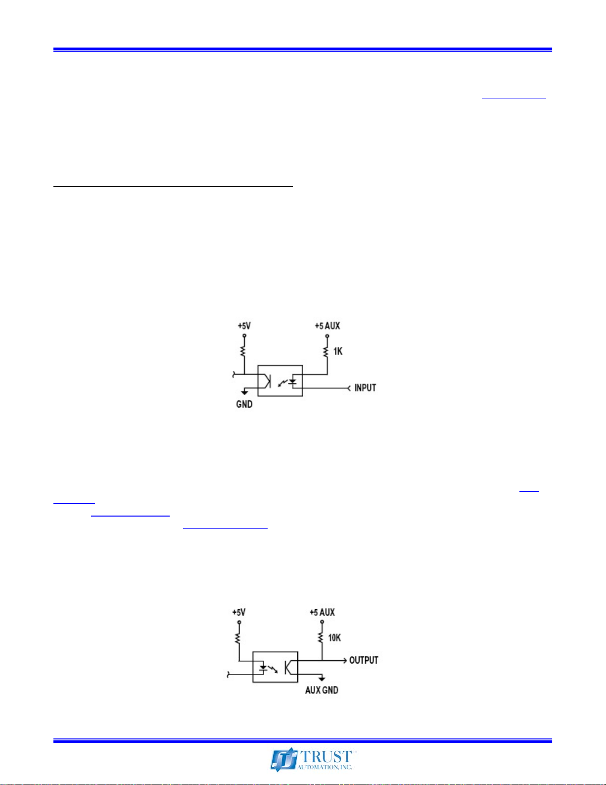
1.9 Enable Input
The ENABLE input can be selected as active-high or active-low logic at SW1 position 1. (See table 4.8
The input must be pulled to logic low (ISO GND) or logic high (ISO +5) for the TA333 to operate. The
ENABLE line is pulled up internally to ISO +5. The TA333 provides an isolated +5V source at connector
J3 and J4 with a maximum draw of 100mA. If the application requires more current, the user must
supply an external 5V that must be referenced to the ISO ground connection.
The TA333 must not be enabled during power up.
If the drive is powered up when enabled, the drive
will not enable and will assert FAULT. The ENABLE input must then be cleared and re-asserted to
enable the drive.
Note: A minimum sinking capability (I
) of 5mA is required.
OL
Note: Logic low input minimum voltage (V
) is 0.8V. Logic high input minimum voltage (VIH) is 2.0V with
IL
a maximum on 5.2V.
See circuit in the following figure:
)
Figure 1 – Enable Circuit
1.10 FAULT Output
The TA333 FAULT output is selectable as active-high or active-low logic, set at SW1 position 2. (See
table 4.8
graph. (See section 2.4)
the serial monitoring port. (See section 1.16)
Note: Logic output high minimum voltage (V
0.8V.
See circuit in the following figure:
) The TA333 will assert FAULT upon over-current or thermal overload based on the SOA
Past FAULT information is stored in internal memory and may be accessed at
) is 2.5V. Logic output low maximum voltage (VOL) is
OH
Figure 2 – Fault Circuit
10-Apr-09 Page 11 of 38
Page 12
Trust Automation, Inc. TA333 High Power Linear Servo Amplifier
1.11 Ground Connections
Command and Signal Logic
Connections to a motion controller must be referenced to ISO ground at J2. These signals include
Enable, FAULT, DTS and the analog command inputs. For single-ended command signals, reference
the TA333 command A- and B- inputs to ISO ground on connector J2.
ISO Ground and all user interface signals on J2, J3 and J4 are isolated from drive power GND and the
External 24V GND with a minimum 1500V hipot separation.
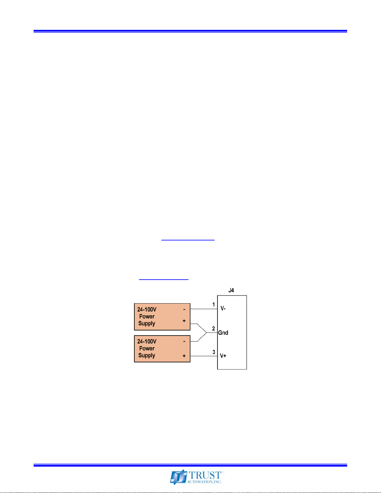
1.12 Drive Power Supply
A pair of matching power supplies (24V to 100V) must be used to power the TA333. A high quality
switching supply is suitable for most applications. These supplies tend to be small, affordable, and
highly available. Trust Automation recommends supplies with an output ripple less than 100mV. Some
high quality supplies available offer less than 50mV. In some cases, particularly where there is great
concern for noise interference, a linear power supply, regulated or unregulated, will be required. For
unregulated supplies, verify that the voltage supplied either at V+ or at V- does not exceed the absolute
maximum supply voltage of 100V. Also note that the supplies must be within 12V of each other or a
supply fault will be generated.
When using the TA333 or any linear servo amplifier, power supply voltage that is not delivered to the
motor will be lost as heat in the amplifier. (See section 1.14)
When selecting supplies for a given motor application it is recommended that the total voltage be
approximately 20V more than the required motor voltage. (The TA333 can drive to within ~ 8V of the
supply). Excessive supply voltages will result in higher peak wattage dissipation. Reference the SOA
graph for actual currents allowed. (See section 2.4)
Figure 3 – Drive Power Connection
Connect the positive supply positive “+” to V+ and the positive supply negative “-” to GND. Connect the
negative supply positive “+” to GND and the negative supply negative “-” to V-. This is shown in Figure
3 above.
Note: When designing a system E-stop, never cut the motor leads. Doing so will result in a runaway
condition and may damage the TA333. Always cut the incoming DC supply (crowbar with a low value
resistor) to the TA333 to produce a rapid stop.
10-Apr-09 Page 12 of 38
Page 13

Trust Automation, Inc. TA333 High Power Linear Servo Amplifier
1.13 Optional External 24VDC Supply
The TA333 internal logic may optionally be powered by an external 24VDC (±5%) source for
convenience when using serial monitoring or in extremely noise sensitive applications. The external
power connection is at J1. The internal 24V source provides power by default automatically but is
disabled if an external source is connected.
When internally powered, some low level noise may be generated by this supply that may have an
effect on the drive performance. While the noise level is small, it may be a factor depending on the
application. When externally powered, the electrical noise level is further reduced, providing the
quietest operation possible. When externally powered, there will be 50-100mV of random electrical
noise on the motor outputs. When internally powered, there will be about 150mV at 160 kHz riding on
the background 50-100mV of random noise.
1.14 Power Dissipation Calculations
Since the TA333 Power stage is linear, voltage not applied to the motor is converted directly to heat.
Heat generated by the drive is directly proportional to the voltage drop (across the amplifier) multiplied
by the motor current. (Think of a linear amplifier as a large variable resistor, current out = current in.)
Heat dissipation is a critical factor when the motor is in a stalled motion condition. (low voltage at the
motor, but high current output). The heatsink is limited to a maximum of 600W continuous dissipation.
Peak dissipation is limited to 1350W for a very short time period (<1ms). A practical design should limit
peak dissipation to 1000W or less. Actual dissipation limits depend on specific conditions including
temperature, load dynamics and event time. For most accurate peak dissipation allowable, see SOA
chart. (See section 2.4)
The TA333 features a microprocessor that constantly monitors the wattage across the drive to protect
the Class-AB power stage from damage. At any given moment in time there is one power device (upper
or lower) that is handling the majority of the drive wattage regardless of whether the load is a floating
brushless motor or a ground-referenced brushed-type load. Calculations are based on the highest
current and voltage across any phase with respect to the power supply ground.
When predicting SOA wattage limits with a brushless motor (or single brushed-type motor in bridge
mode), use half of the expected voltage across any pair of phase leads against the voltage of one of
the two supplies.
For a brushed-type load that is directly referenced to the power supply ground, use the full predicted
voltage across the motor against one of the two supplies.
Brushless example:
Assume a have a pair of 72V supplies and a motor that is expected to require 15A peak load at a phase
to voltage requirement of 20V according to calculations. Because a brushless motor voltage is specified
as phase-to-phase, we will divide the predicted voltage in half to give a ground referenced motor
voltage of 10V.
P
D
= I
motor
(V
supply
– V
I
= 15A [calculated based on required torque]
motor
V
= 10V [calculated based on velocity]
motor
V
= 72V [one of two 72V supplies]
supply
motor
)
10-Apr-09 Page 13 of 38
Page 14

Trust Automation, Inc. TA333 High Power Linear Servo Amplifier
PD = 15A (72V-10V)
= 930W *
* This is over the 600W continuous dissipation rating so there will be a short time limit applied based on
the SOA chart before FAULT is generated. See SOA chart. (See section 2.4)
Dual-brushed example:
Assume a pair of 48V supplies and a motor that is expected at any one time to require 10A peak load at
a phase voltage requirement of 12V according to calculations. Because the motor(s) are referenced to
the power supply ground, the calculations are based on the full motor voltage.
P
D
= I
motor
(V
supply
– V
motor
)
I
= 10A [calculated based on required torque]
motor
V
= 12V [calculated based on velocity]
motor
V
= 48V [one of two 48V supplies]
supply
P
= 10A (48V-12V)
D
= 360W *
* This is under the 600W continuous dissipation rating, but the current is over the 6A continuous, so
there will be a time limit applied based on the SOA chart before FAULT is generated (10A @ 30c =
~3.2sec before fault). (See SOA chart, section 2.4)
1.15 Motor Connections
The TA333 motor connections are made at connector J5. The available output voltage is limited to the
supply voltage, less approximately 8V off each rail. With ±48V supplies, there will be 80V available
across the motor before the output starts to clip. Pin 1 on J5 is earth ground and is electrically isolated
from all power connections. By physically connecting the TA333 chassis and the motor chassis to an
earth ground, immunity from external noise sources is increased.
Note: When designing a system E-stop, never cut the motor leads. This will result in a runaway
condition and may damage the TA333. Always cut the incoming DC supply (crowbar with a low value
resistor) to the TA333 to produce a rapid stop.
Brushless Motor
The phase outputs A, B and C correlate to most motor callouts as U, V and W or in some cases R, S
and T. (See application examples 5.1, 5.2, and 5.3)
Brushed Motor in Bridged Mode
To drive a single brushed motor in bridge mode, connect the motor “+” lead to the A phase output and
the motor “–” lead to the C phase output. This configuration allows the full bipolar supply voltage to be
driven across the motor in any direction of rotation. The motor can be a traditional brushed or voice coil
type. (See application example 5.4)
10-Apr-09 Page 14 of 38
Page 15

Trust Automation, Inc. TA333 High Power Linear Servo Amplifier
Dual Brushed Motor Mode
Two independent motors or one stepper type motor may be driven in this configuration. For two
brushed-type motors (or voice coils) connect the (+) lead of the first motor to the A phase output (drive
with the A command) and connect the (–) lead to the power supply common (Pin 2 on J6). Connect the
second motor (+) to the B phase output (drive with the B command) and the (–) lead to the power
supply common. (See application example 5.5)
Stepper Motor
Two coil sets on a stepper type motor may be driven in this configuration. This configuration is the
same as the dual brushed mode except that the two coil sets are in the same motor. The linear
command is driven on command A and B with a motion controller setup to drive a stepper motor
sinusoidally. (See application example 5.6)
1.16 Serial Monitoring
The TA333 has a high speed data port for monitoring drive performance and logging of fault conditions.
The five pin port at J2 provides access to a TTL serial data stream presented at 230,400 baud. Set up a
terminal program (such as HyperTerminal) with the baud rate set to 230,400 bits per second, 8-bit data,
no parity, 1 stop bit, and flow control to no handshaking.
An optional TTL to USB serial cable may be ordered as CBLZ-0910-01 to facilitate connection to a PC.
Reference the FTDI installation guide for installing the TTL to USB serial cable.
Figure 4 – Com Port Settings for Serial Communication
When the TA333 is powered up, the serial port will transmit the firmware version and the drive mode
set by SW1 position 5 through 8. (See section 4.10 for more information)
Figure 5 - Firmware Version and Drive Mode
10-Apr-09 Page 15 of 38
Page 16

Trust Automation, Inc. TA333 High Power Linear Servo Amplifier
Once the TA333 is enabled, data will begin transmitting in the following format:
Figure 6 – Data Transmission Format, HyperTerminal
Figure 6 shows the drive set to brushless motor mode, no faults, heatsink at 22°C, positive supply at
24V and negative supply at 24V. There is less than 1A current flow and integer math has placed the
dissipation at 9W.
The data stream may be stopped by transmitting “s” followed by “Rtn.” The data stream will resume
upon sending the “s” + “Rtn” sequence again. Data layout is formatted as:
Data field Data Name Description
1 Fault Amp fault data (See fault chart)
2 Temp, Celsius Temperature of heat sink, SOA de-rated as temperature rises.
3 Phase Voltage The captured phase voltage
4 + Supply V Positive supply voltage
5 - Supply V Negative supply voltage
6 Phase Current The highest captured phase current
7 Wattage Amp dissipation wattage based on data gathered
Faults are formatted as:
Fault Name Description
0x0000 No Fault Operation Normal
0x0002 Temp Over temp fault at 70c, The TA333 will disable @ 90c
0x0001 Supply Under voltage @ 20V, Over voltage @ 105V
0x0004 Current Over current fault based on time limit and SOA
0x0008 Wattage Over continuous wattage limit based on time and SOA
0x0010 Peak Wattage Peak wattage limit based on time and SOA
0x0020 Enable Enable fault if drive is powered up in the enabled state
Table 1 – Data Transmission Format
Table 2 – Fault Codes
10-Apr-09 Page 16 of 38
Page 17

Trust Automation, Inc. TA333 High Power Linear Servo Amplifier
The TA333 captures the last ten fault conditions that have occurred. This data can be accessed by
sending “p” followed by “Rtn” either before enabling or after sending the stop “s” command.
Figure 7 – Sample Fault Printout
If the TA333 is powered up with the optional 24V input and the enable signal is active, two faults will be
generated. The first reported fault will be 0x0020 enable fault followed by 0x0021, indicating there is a
supply fault in addition to an enable fault.
10-Apr-09 Page 17 of 38
Page 18

Trust Automation, Inc. TA333 High Power Linear Servo Amplifier
V
V
2.0 General Specifications
2.1 Electrical Specifications
Feature Units
Supply Voltage (Bipolar)
Equivalent Motor Voltage
External 24V Supply
Maximum Output Current
Continuous Output Current
Quiescent Bias Current
Fault
Enable
Command Input
Command Input Impedance
Torque Gain
Bandwidth
Harmonic Distortion THD
Signal to Noise ratio SNR
Trapezoidal Bandwidth
Min Load Inductance
Min non-inductive load
Table 3 – Electrical Specifications
V ± 24 – ± 100
V Vsup – 8V (~ 8V from either supply rail)
VDC 24 ± 5% @ 1.0A
A 25 (See SOA Chart section 2.4)
A 6 RMS (8.6 Peak)
A ~0.5 (Class A/B biasing current)
V 5 TTL Level 0 or 1
V 5 TTL Level 0 or 1
V ±10 (±12 absolute max)
kΩ 10
A/V 1.0 - 2.5
kHz 5.0 (0.820mh / 0.65 Ω Load)
% 0.036 (Voltage to Current)
db -79.06 (1A @ 1kHz)
kHz 3.0 (Consult factory for higher speeds)
mH 0.100
Ω 2.0
alue
2.2 Mechanical Specifications
Feature Units
Length
Width
Height
Weight
Table 4 – Mechanical Specifications
in (cm) 14.90 (37.85)
in (cm) 7.69 (19.53)
in (cm) 4.70 (11.94)
lb (kg) 13.5 (6.12)
2.3 Environmental Specifications
Feature Details
Maximum Altitude
Temperature (ambient)
Normal operation 5°C to +40°C
Temperature de-rating See SOA Chart – Section 2.4
Storage -40°C to +70°C
Heatsink +70° C Maximum
Heat Dissipation (@ 25°C)
Continuous 600W
Peak 1350W, See SOA Chart – Section 2.4
Airflow
Humidity
Operating 10% to 70%, non-condensing
Storage 10% to 95%, non-condensing
Pollution Degree 2
Table 5 – Environmental Specifications
6,560ft (2,000 meters)
Internal fans, variable speed, thermally controlled
Non-conductive, non-condensing
alue
10-Apr-09 Page 18 of 38
Page 19

Trust Automation, Inc. TA333 High Power Linear Servo Amplifier
2.4 TA333 Safe Operating Area Curve (SOA)
The TA333 features a micro processor that constantly monitors the operating conditions on the
amplifier to prevent damage. This processor continuously calculates the dissipated wattage and sets a
fault threshold based on heatsink temperature, supply voltage, and motor current. The formulas for
calculated limits are current, wattage and temperature.
Current Limit
For currents that result in a dissipation wattage below 600W, the processor limits the time
logarithmically from infinite time at 6A down to 500ms at 25A. (See current vs. time graph).
Wattage Limit
If the resulting dissipation wattage exceeds 600W, the time to fault is much shorter as it is now
operating in the “knee” of the SOA curve. (See wattage vs. time graph).
Temperature Limit
The microprocessor takes into account the heatsink temperature when calculating the wattage time
limit. Time to fault is de-rated at about 15ms per 20°C rise. (See temp vs. time for an example at
876W). If the heatsink temperature exceeds 70°C FAULT is generated, and at 90°C the drive will
shutdown.
Figure 8 – TA333 SOA Curve
10-Apr-09 Page 19 of 38
Page 20

Trust Automation, Inc. TA333 High Power Linear Servo Amplifier
Current vs. Time
25
23
21
19
17
15
Current
13
11
9
7
5
500 1500 2500 3500 4500 5500 6500
Time (ms)
Figure 9 – Output Current vs. Time Graph for Time to Fault @ ~30°C
W attage vs. Time
1400
1300
1200
1100
1000
Wattage
900
800
700
600
15 25 35 45 55 65 75 85
Tim e (ms)
Figure 10 – Dissipation Wattage vs. Time for Time to Fault @ ~30°C
10-Apr-09 Page 20 of 38
Page 21

Trust Automation, Inc. TA333 High Power Linear Servo Amplifier
Temp/W 700 800 900 1000 1100 1200 1300
25
30
35
40
45
50
55
60
65
70
Figure 11 – Temperature De-rating, Time to Fault for Dissipation Wattages vs. Heatsink Temperature
For a given wattage, the time to generate a fault decreases with temperature. For example, at 25°C the
TA333 will sustain 900W for ~45ms before fault generation. If the heatsink is at 60°C, then only ~21ms
will be allowed before fault generation.
92.64 63.17 45.06 33.31 25.35 19.75 15.70
85.14 58.05 41.41 30.61 23.29 18.15 14.43
77.82 53.06 37.85 27.98 21.29 16.59 13.18
70.67 48.19 34.38 25.41 19.33 15.06 11.97
63.71 43.44 30.99 22.91 17.43 13.58 10.79
56.93 38.82 27.69 20.47 15.57 12.13 9.65
50.33 34.32 24.48 18.10 13.77 10.73 8.53
43.91 29.94 21.36 15.79 12.01 9.36 7.44
37.68 25.69 18.33 13.55 10.31 8.03 6.38
31.62 21.56 15.38 11.37 8.65 6.74 5.35
10-Apr-09 Page 21 of 38
Page 22

Trust Automation, Inc. TA333 High Power Linear Servo Amplifier
2.5 TA333 Output Frequency Response
The TA333 design provides a relatively flat current output response up to 5 kHz for most motors.
Lower inductance motors (0.10mH) will yield a higher bandwidth and higher inductance motors (1015mH) will yield a lower bandwidth. There is no actual limit on how high the inductance can be, but
there are practical limitations based on Ohms Law that limit actual bandwidth response in a motor.
Excessively low inductances (<0.1mH) can result in current loop instability and result in uncontrolled
oscillations.
The TA333 has been factory tuned to give optimal performance over a wide variety of industry standard
motors. If the intended application for the TA333 requires a motor outside the usual inductance range,
and the full 5 kHz throughput is required, please contact support@trustautomation.com
requirements.
The following was plotted with a 1V command into a 0.820mH load with a DC resistance of 0.65Ω.
to discuss your
B Done
dB
dB/div
5.2182681 kHz -12.886 dB
0
5
SRS
-50
100 Hz
dB
Freq. Resp. Log Mag 3.99 s
50 kHz
11/29/07 15:20:18
Figure 12 – TA333 Frequency Response
10-Apr-09 Page 22 of 38
Page 23

Trust Automation, Inc. TA333 High Power Linear Servo Amplifier
3.0 Mechanical Information
The TA333 must be mounted in such a way that there is clear airflow into and out of the heatsink and
integral cooling fans. Ideally there would be at least 4” of clearance on both ends. For best results
mount the unit vertically with the nose up (air flow exit), to take advantage of the chimney effect of heat
rising.
3.1 Dimensions
Figure 13 – TA333 Mechanical Dimensions
10-Apr-09 Page 23 of 38
Page 24

Trust Automation, Inc. TA333 High Power Linear Servo Amplifier
4.0 Connector and Switch Information
4.1 Front Panel Connector and Switch Layout
Figure 14 – TA333 Front Panel
4.2 Connector Types
Connector # # Pins Manufacturer & Part Number Description
J1 2 Phoenix 1827703 External 24VDC Supply
J2 6 FTDI P/N TTLUSB TTL to USB
J3 10 Wago P/N 733-110 Command Signals
J4 5 Wago P/N 733-105 Hall Sensors
J5 4 Phoenix 1825336 Motor Signal
J6 3 Phoenix 1777992 Motor Power
Table 6 – Connector Types
4.3 J1 – External 24VDC Supply
Pin # Description
1 24V External Supply
2 Common (Isolated)
Table 7 – External 24VDC Supply Connector
4.4 J2 – Serial Monitoring Port
Pin # Description
1 ISO Gnd
2 CTS (Not used)
3 V
4 TXD
5 RXD
6 RTS (Not used)
Table 8 – Serial Monitoring Connector
J2 provides a TTL level serial port to monitor the operating conditions on the load and the internal
health of the TA333. The optional TTL Serial to USB cable provides a convenient conversion for
viewing the data with any terminal program such as Windows HyperTerminal. (See section 1.16)
ISO
10-Apr-09 Page 24 of 38
Page 25

Trust Automation, Inc. TA333 High Power Linear Servo Amplifier
4.5 J3 – Command Signals
Pin # Description
1 Command Signal Input Phase A+
2 Command Signal Input Phase A3 Command Signal Input Phase B+
4 Command Signal Input Phase B5 Dynamic Transconductance Select Bit D0
6 Dynamic Transconductance Select Bit D1
7 ENABLE (Referenced to ISO Gnd)
8 FAULT (Referenced to ISO Gnd)
9 ISO Gnd
10 V
Table 9 – Motor Command Signals Connector
(Internal supplied +5V@ 100ma Optical Isolation)
ISO
4.6 J4 – Hall Sensor Input
Pin # Description
1 ISO +5 (20mA Maximum)
2 ISO Gnd)
3 Hall A
4 Hall B
5 Hall C
Table 10 – Hall Sensor Input Connector
Note: If the motor has differential Hall outputs, only connect the “+” Hall outputs to J4 and leave the “–”
Hall signals unconnected. (Do not tie to ground, the motor will be damaged.)
Note: If the Hall sensors require more than 20mA, an external +5V must be supplied.
(See application example 5.3)
4.7 J5 – Motor Signals
Pin # Description
1 Shield (tied to chassis)
2 Motor Phase A / U / R
3 Motor Phase B / V / S
4 Motor Phase C / W / T
Table 11 – Motor Signals Connector
Note: Phase A, B and C are the same as U, V and W or R, S and T found on most commercial motors.
4.8 J6 – Motor Power
Pin # Description
1 B- Supply
2 Common (Isolated)
3 B+ Supply
Table 12 – Motor Power Connector
10-Apr-09 Page 25 of 38
Page 26

Trust Automation, Inc. TA333 High Power Linear Servo Amplifier
4.8 SW1 – Switch Settings
Switch # Function – (0 / Down / On) Function – (1 / Up / Off)
1 /ENABLE (drive enabled on low Input) ENABLE (drive enabled on high input)
2 /FAULT (FAULT low true output) FAULT (FAULT high true output)
3 Gain and DTS Settings See Following Chart for Function Selection
4 Gain and DTS Settings See Following Chart for Function Selection
5 Trapezoidal Commutation Sinusoidal Commutation
6 60° Hall Commutation 120° Hall Commutation
7 Brush type motor (or voice coil) Brushless type motor
8 Dual Brush type motor (unbridged) Single Bridged motor (bridged)
Table 13 – SW1 Settings
4.9 SW1 – Switch 3 and 4, Fixed Gain and DTS Settings
Setting SW1-3 (DTS D0) SW1-4 (DTS D1)
10Vin = 10A out
10Vin = 15A out
10Vin = 20A out
10Vin = 25A out
DTS Active
Table 14 – Fixed Gain and DTS Switch Settings
Figure 15 – Fixed Gain and DTS Settings
(Note: “Down” is toward the heatsink, “Up” is away from the heatsink)
Down (0) Down (0)
Up (1) Down (0)
Down (0) Up (1)
Up (1) Up (1)
Up (1) Up (1)
10-Apr-09 Page 26 of 38
Page 27

Trust Automation, Inc. TA333 High Power Linear Servo Amplifier
4.10 SW1 – Switch 5-8 Motor type
(See section 1.3 for more information)
Function (Motor type) SW1-5 SW1-6 SW1-7 SW1-8
Brushless motor, sinusoidal commutation Up (1) Up (1) Up (1) Up (1)
Brushless motor, trapezoidal commutation, 120° Halls Down (0) Up (1) Up (1) Up (1)
Brushless motor, trapezoidal commutation, 60° Halls Down (0) Down (0) Up (1) Up (1)
Single brushed motor (or voice coil) bridge mode Up (1) Up (1) Down (0) Up (1)
Dual brushed motor (voice coil or stepper) unbridged mode Up (1) Up (1) Down (0) Down (0)
Table 15 – SW1 Motor Type Selection
Figure 16 – SW1 Motor Type settings
10-Apr-09 Page 27 of 38
Page 28

Trust Automation, Inc. TA333 High Power Linear Servo Amplifier
4.11 Isolation Diagram
Figure 17 – TA333 Isolation Diagram
10-Apr-09 Page 28 of 38
Page 29

Trust Automation, Inc. TA333 High Power Linear Servo Amplifier
4.11 Isolation Diagram (Cont.)
Figure 18 – TA333 Isolation Diagram
10-Apr-09 Page 29 of 38
Page 30

Trust Automation, Inc. TA333 High Power Linear Servo Amplifier
5.0 Application Examples
5.1 Brushless Motor, Sinusoidal (Differential Command Input)
Figure 19 – Application Example 1
This figure shows the TA333 operating in sinusoidal mode with differential command inputs. Active-low
enable, active-low FAULT, driving a single brushless servo motor. The TA333 is set for a fixed current
limit of 20A with a transconductance of 2.0A/V.
10-Apr-09 Page 30 of 38
Page 31

Trust Automation, Inc. TA333 High Power Linear Servo Amplifier
5.2 Brushless Motor, Sinusoidal (Single Ended Command Input)
Pending
Figure 20 – Application Example 2
This figure shows the TA333 operating in sinusoidal mode with single ended command inputs. Activelow enable, active-high FAULT, driving a single brushless servo motor. The TA333 is set for a fixed
current limit of 10A with a transconductance of 1.0A/V.
10-Apr-09 Page 31 of 38
Page 32

Trust Automation, Inc. TA333 High Power Linear Servo Amplifier
5.3 Brushless Motor, Trapezoidal, Hall Commutation
Pending
Figure 21 – Application Example 3
This figure shows the TA333 operating in trapezoidal mode with single ended command input. Activelow enable, active-low FAULT, driving a single brushless servo motor, and using Hall Effect sensors at
120° timing for trapezoidal commutation. The TA333 is set for a fixed current limit of 15A with a
transconductance of 1.5A/V.
Hall Sensors are connected to J4. If the motor has differential Hall outputs, only connect the “+” Hall
outputs to J4 and leave the “–” Hall signals unconnected. (Do not tie to ground, the motor will be
damaged.) Note that Hall 5V power supplied by the TA333 is limited to 20ma. If the motor hall sensors
require >20mA for operation, an external 5V power source must be used.
10-Apr-09 Page 32 of 38
Page 33

Trust Automation, Inc. TA333 High Power Linear Servo Amplifier
5.4 Brush Motor, Bridge Mode
Pending
Figure 22 – Application Example 4
This figure shows the TA333 operating in brushed bridge mode with differential command inputs.
Active-low enable, active-high FAULT, driving a single brush type servo motor. The TA333 is set for a
fixed current limit of 25A with a transconductance of 2.5A/V with active DTS input control.
10-Apr-09 Page 33 of 38
Page 34

Trust Automation, Inc. TA333 High Power Linear Servo Amplifier
5.5 Brush Motor, Dual Motor Mode
Pending
Figure 23 – Application Example 5
This figure shows the TA333 operating in brushed dual mode with single ended command inputs.
Active-low enable, active-high FAULT, driving two brush-type (or voice coil) servo motors
independently. The TA333 is set for a fixed current limit of 15A with a transconductance of 1.5A/V.
10-Apr-09 Page 34 of 38
Page 35

Trust Automation, Inc. TA333 High Power Linear Servo Amplifier
5.6 Stepper Motor, Sinusoidal Commutation
Pending
Figure 24 – Application Example 6
This figure shows the TA333 operating in brushed dual mode with differential command inputs. Activelow enable, active-low FAULT, driving a stepper motor sinusoidally. The TA333 is set for a fixed current
limit of 20A with a transconductance of 2.0A/V.
10-Apr-09 Page 35 of 38
Page 36

Trust Automation, Inc. TA333 High Power Linear Servo Amplifier
6.0 W arranty
Trust Automation Inc.
(Limited 1 Year Warranty)
GENERAL - All hardware products sold by Trust Automation Inc. are warranted against defects in material
and workmanship for a period of one (1) year from the date of shipment. If you believe that a Trust
Automation Inc. hardware product you have purchased has a defect in material or workmanship, or has failed
during normal use within the warranty period, please contact Trust Automation Inc. at (805) 544-0761 for
assistance and/or a Return Material Authorization Number (RMA#).
If product repair or replacement is necessary, the Customer will be responsible for all return shipping charges,
freight, insurance and proper packaging to prevent damage in transit, whether or not the product is covered
by this warranty. During the warranty period, product determined by Trust Automation Inc. to be defective in
form or function will be repaired or, at Trust Automation Inc.'s option, replaced at no charge. Trust
Automation Inc. will pay the return shipping charges (ground for US based shipments, most economical air for
international shipment. Customer may elect to change shipment method and pay the difference.), for products
that have been repaired or replaced. All duties and taxes remain the responsibility of the customer. All
shipments of repaired or replaced products will be F.O.B. at Trust Automation Inc. headquarters in San Luis
Obispo, California.
For tracking purposes, products to be repaired or replaced must be returned to Trust Automation Inc. with a
Trust Automation Inc. RMA#, and a Purchase Order. The standard charge for non-warranty repair work is
$120 per hour, plus parts with a minimum charge of $120. Trust Automation will provide repair cost esti mate
prior to performance of out of warranty repair work.
Material and workmanship used in the repair and replacement of Trust Automation products under this
warranty are warranted additionally against defects for a period of ninety (90) days from the date of return
shipment to the customer.
LIMITATIONS - This warranty does not apply to damage resulting from accidents or any Customer actions,
such as mishandling, misuse, improper interfacing, operation outside of design limits, improper repair, or
unauthorized modification. No other warranties are expressed or implied. Trust Automation Inc. liability shall
be limited to the actual purchase price of any defective unit or units of equipment to which a claim is made,
and shall in no event include the Customer's manufacturing costs, lost profits or goodwill, or any other direct,
indirect, special, incidental or consequential damages.
10-Apr-09 Page 36 of 38
Page 37

Trust Automation, Inc. TA333 High Power Linear Servo Amplifier
7.0 TA333 Hardware Revision History
Revision Date Description
A.0 15 Dec 07 Alpha Hardware Release
A.1 15 May 08 Added Brush type motor support
10-Apr-09 Page 37 of 38
Page 38

Trust Automation, Inc. TA333 High Power Linear Servo Amplifier
8.0 TA333 Manual Revision History
Revision Date Description
v0.10 15 Aug 08 Initial Release (ALPHA)
v0.11 10 Oct 08 Data corrections
v0.12 30 Jan 09 Formatting changes
V0.13 10 April 09 Release (BETA)
10-Apr-09 Page 38 of 38
 Loading...