

Page 1

TRUST SURVEILLANCE INTERFACE 801 USB
1
UK
1 Introduction
This manual is intended for users of the ‘TRUST SURVEILLANCE INTERFACE 801
USB‘. This USB-interface can be used to hook up a video camera with sound and get
a fully programmable recording of your video surveillance.
The Trust Surveillance Software allows for 24/7 surveillance of the observed area
from a remote location, via the Internet or a network link. The observed area and the
audio/video sensitivity can be set for an accurate detection level.
Video or audio detection can be automatically provided with an exact date and time
rendering. Also, previously programmed noise signals can be played whenever some
motion is detected.
Make a complete (cordless) surveilla nce system with a surveillance camera from the
Trust product range. Ideal for all forms of surveillance and observance, for instance
for protection against burglary, supervision over children, at store entrances, at
checkouts, in warehouses, parking lots and so on.
2 Safety
Before use, carefully read the following instructions:
1. Do not use the device in damp environments, such as bathrooms, damp
basements, swimming pools, etc.
2. Do not attempt to repair the device yourself. Maintenance should only be
done by qualified repair people.
3. Position the device in such a way that the cables cannot be damaged.
3 Installation
3.1 Hardware Installation
For the installation of the Trust Surveillance Interface 801 USB follow the steps below:
1. Start up your computer.
2. Put the USB plug of the Surveillance Interface 801 USB into a free USB port
of your computer.
3. Windows will detect the ne w hardware and ask for the location of the driver.
4. Place the CD-ROM with the driver and applications into your CD-ROM drive.
5. Select the option where Windows will look for the most suitab le driver.
6. Select the option where Windows searches in a specific location. For a path,
enter: [D:\Driver].
Note: The above letter ‘D’ serves as an example of your CD-ROM drive.
Check which actual letter is used by your computer to denote your
CD-ROM drive.
7. The driver is located. Follow further instructions for the installation. The driver
consists of the following 3 elements:
a) USB Composite Device
b) Trust USB A/V Audio
c) Trust Surveillance Interface 801
8. After the installation of the driver, restart your system.
Page 2

TRUST SURVEILLANCE INTERFACE 801 USB
2
9. Connect the video cable of your camera to the video connection of the
Surveillance Interface 801 USB. You have 2 options:
a) S-VHS connection (4pins mini DIN plug)
b) Composite connection (single cinch plug)
10. Connect the sound cable of your camera to the sound connection of the
Surveillance Interface 801 USB (double cinch plug L/R)
Note: In order for the sound function of your Surveillance Interface 801
USB to be fully operational, you must have a sound card installed
on your computer.
3.2 Software Installation
3.2.1 Trust Surveillance Software
The Trust Surveillance Software must be installed on the local computer to which your
camera is connected. For installation, follow the steps below:
1. Start up Windows.
2. Place the CD-ROM with the driver and applications into your CD-ROM drive.
3. The Trust Softwa re Installer will start up aut omatically. If it doesn’t, go to ‘Start
– Execute’ and type [D:\Setup.exe] in the entry field. Then click ‘OK’. See
Figure 1.
Note: The language selection menu in the left box concerns the
rendering of the installer in various languages. The application
and comprehensive user manual only come in English.
4. Click the button ‘SURVEILLANCE SOFTWARE’ in order to start up the
installation of this application.
5. Next, fill out your p articulars in the fie ld that will appear. The required serial
number can be found on the sleeve of your CD-ROM.
6. Follow the instructions to continue installation.
3.2.2 Trust Remote View Software
The Trust Remote View Software is to be installed on an external computer. Follow
the instructions below for further installation:
Note: Both the local computer with the camera connected to it and the
external computer must have a modem or a network link.
1. Start up Windows.
2. Place the CD-ROM with the driver and applications into your CD-ROM drive
and start up the Trust Software Installer. See Figure 1.
3. Click the ‘REMOTE VIEW SOFTWARE’ button to start up the installation of
this application.
4. Follow the instructions onscreen.
3.2.3 Trust IP MultiCast Software
The Trust IP MultiCast Software must be installed on an external computer. For
installation, follow the instructions below:
Note: The IP MultiCast Soft ware will only funct ion in an Intranet/LAN
network. It will no t work via WAN/Inte rnet. The local and external
computer must be linked to the same network.
1. Start up Windows.
Page 3
TRUST SURVEILLANCE INTERFACE 801 USB
3
UK
2. Place the CD-ROM with the driver and applications into your CD-ROM drive
and start up the Trust Software Installer. See Figure 1.
3. Click the ‘IP MULTICAST SOFTWARE’ button to start up the installation of this
application.
4. Follow the directions onscreen.
4 Usage
Below, an outline will be given of h ow to use the applications. Consult the
comprehensive user manual on the CD-ROM for a detailed description of the different
functions. Also co nsult the detaile d help function s of the applica tions. You will find
these in ‘Start – Programs – Trust – Surveillance Interface 801’.
Place the CD-ROM in your CD-ROM drive and start up the Trust Software Installer.
Click the ‘READ MANUAL’ button to read the user manual from the CD-ROM. See
Figure 1.
4.1 Trust Surveillance Software
Go to ‘Start – Programs – Trust – Surveillance Interface 801’ and select the option
‘Trust Surveillance Software’ in o rder to start up this application on yo ur local system.
The main screen will appear, with the video picture from your camera in the centre.
In the bottom right of the main screen you will see your available hard disk space and
the time available for video-recording.
Note: If the hard disk space is 150MB is, the recording will stop or your
old log files will be o verwritten.
For a description of the main buttons in the tool bar see the table below:
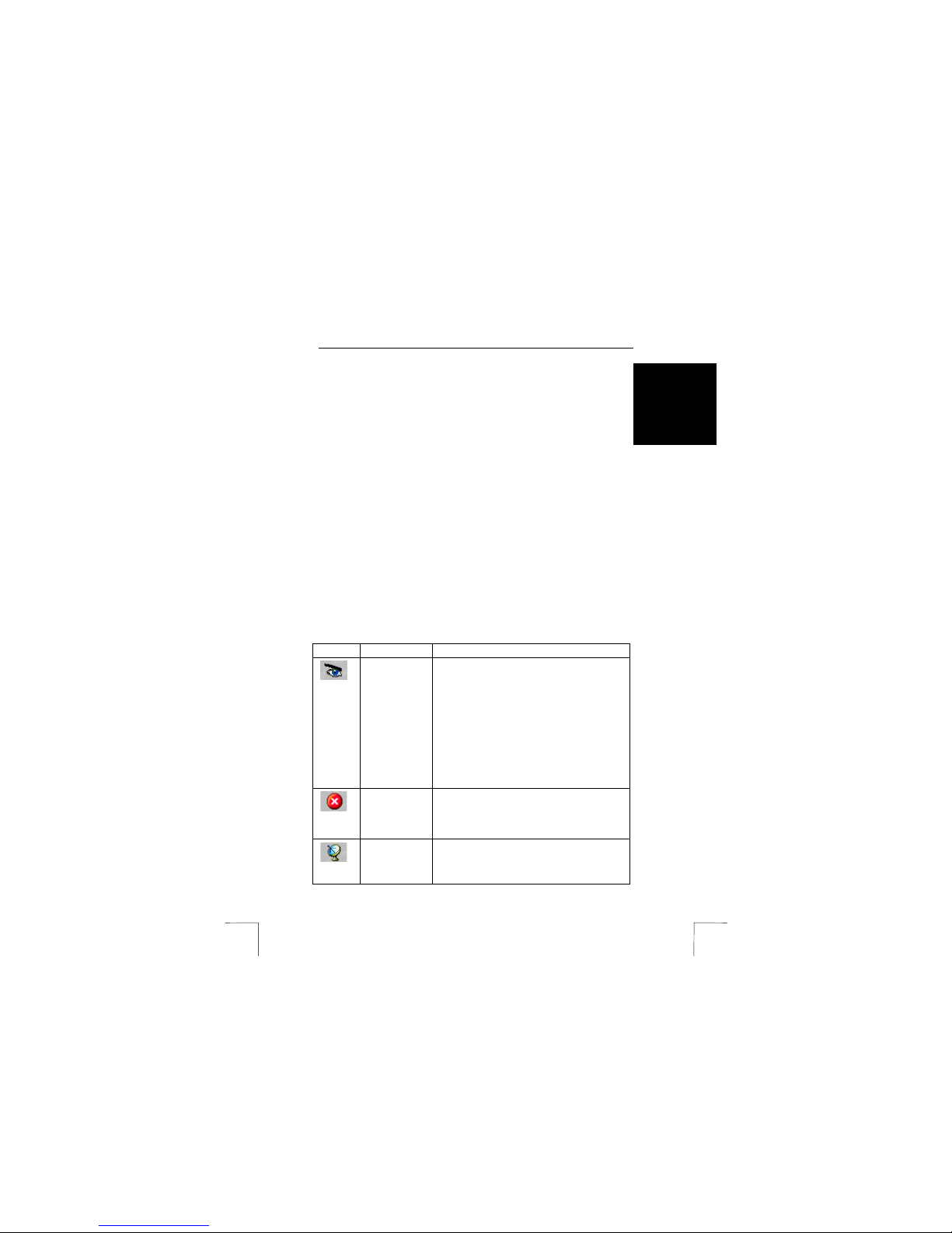
Button Function Description
Start Monitor Start the audio/video surveillance and recording. If
you click this button, a submenu will pop up with
the following options:
* Start Monitor All:
start both audio and video
surveillance/recording.
* Camera name:
only starts video
surveillance/recording.
* Audio Sensor:
only starts audio
surveillance/recording.
* Start schedule monitor:
starts the
surveillance/recording in accordance with a preset surveillance schedule.
Stop Monitor Stops the audio/video surveillance/recording. If
you click this button, a submenu will pop up with
the same options as in ‘Start Monitor’. Select the
desired option for stopping the
surveillance/recording.
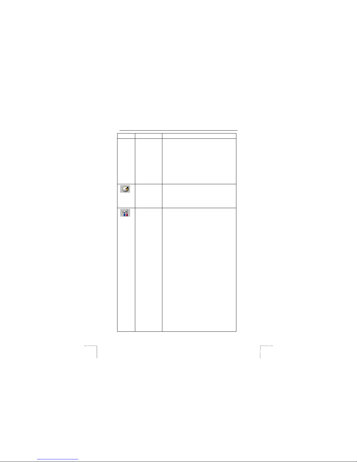
Sensitivity Set the sensitivity of the audio/video recording. If
you click this button, a submenu will pop up with
the following options:
* Video Motion:
to set the sensitivity of the motion
Page 4
TRUST SURVEILLANCE INTERFACE 801 USB
4
Button Function Description
detection. Select a setting between 1 and 99. See
Figure 2. The higher the setting, the more
sensitive the motion detection. As soon as some
motion is detected , the video-recordin g will start.
* Audio Noise:
to set the audio detection. The
audio-recording will start automatically, if the
setting in ‘Environment’ exceeds the setting ‘Set
Audio Sensitivity’. See Figure 3.
Note: The setting in ‘Environment’ is determined
by the sound recording settings of your computer.
This can be used as a reference for the sensitivity
setting. See section 4.1.1 for further details.
Record Setting Set the picture quality of the video recording.
Select a setting between 1 and 5. The higher the
setting, the better the picture quality of the videorecording.
Note: Better picture qua lity will take up more
memory space.
Preference Click this button to alter the general settings and
video settings. See Figure 4. These are the
settings you can alter:
* Capture Driver:
Select your video capture
device here (Trust Surveillance Interface 801
USB).
* Video Format:
Set the video picture format of
your camera (RGB15, RGB24, YUV9, etc.)
* Video Source:
Set the video standard (PAL,
NTSC, SECAM) of your camera, as well as picture
settings (clarity contrast, etc.)
* Mask Visible:
enable or disenable the ‘Mask’
function in the video picture during the video
surveillance/recording.
* Start Monitor After:
the surveillance/recording
will start after the t ime you set here.
* Password:
set a password to protect the
settings and for login via RemoteView and IP
Multicast.
* Pager/Tel Hot Line Setting:
click the ‘Set
Pager…’ button to alter the settings of the
automatic pager function. See Figure 5.
You can enter 6 different telephone/pager
numbers and also attribute these to the function
keys F7 to F12.
The number can be dialled automatically, or by
pressing the function keys. Alternatively, a text
message can be sent along to a pager.
You can then log in directly by means of the
RemoteView or IP Multicast software in order to
Page 5
TRUST SURVEILLANCE INTERFACE 801 USB
5
UK
Button Function Description
view and, if so desired, record the situation.
Note: If your phone supports number display, you
can enable this so that you will see immediately
that the system is calling you.
* Default Alarm:
you can have the local computer
play a sound file when motion has been detected.
Select one of the files from the list, or choose
‘User Define’ for se lecting your own ‘.W AV’’ file.
* Log File Location:
enter the location that the
log file is to be saved to.
* Recycle:
tick this option if you want to overwrite
old log files in case of low hard disk capacity.
* Schedule:
click this button to set schedules for
starting audio/video recordings at set times.
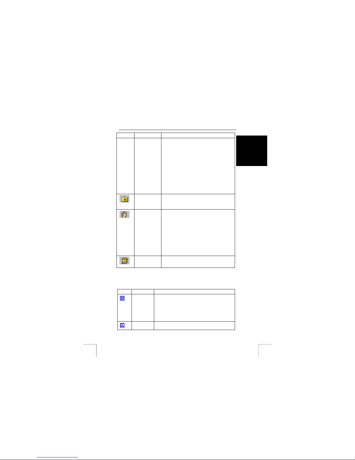
View Log Click this button and then select your camera in
the sub-menu to view all audio/video takes that
were made. You can also upgrade the quality of
the recordings and print selected video stills.
Network Login Click this button and then, in the sub-menu, select
the Internet/intranet link that the Surveillance
Software has to check on the logins of the
RemoteView or IP Multicast software. You have
the following options:
* Intranet Listen on IPX
* Internet/Intranet on TCP/IP
* Webcam Server
* Multicast Server
You can tick more than one option at the same
time.
Modem Login Check the modem for logins of the RemoteView
software via the direct dial-in connection to the
local computer.
Apart from the above main buttons, the Surveillance Software also has a ‘Mask’
function, which allows you to select specific parts of the video picture which you don’t
want to be checked for motion. For possible function buttons, see the table below:
Button Function Description
Add Mask Add a ‘Mask’ to a video picture. With the left mouse
button pressed, drag the mouse over the relevant field in
the picture. A grid will appear on top of the picture. This
grid area will not be ch ecked for motion during the
surveillance.
This option allows you t o just monitor a hallway o r a
window for motion. See Figure 6.
Cut Mask Cut a section from the added ‘mask’ field. This cut is now
available for video surveillance.
Page 6
TRUST SURVEILLANCE INTERFACE 801 USB
6
Button Function Description
Clear Mask Remove all ‘Mask’ fields from the picture. The complete
video picture is now available for video surveillance
again.
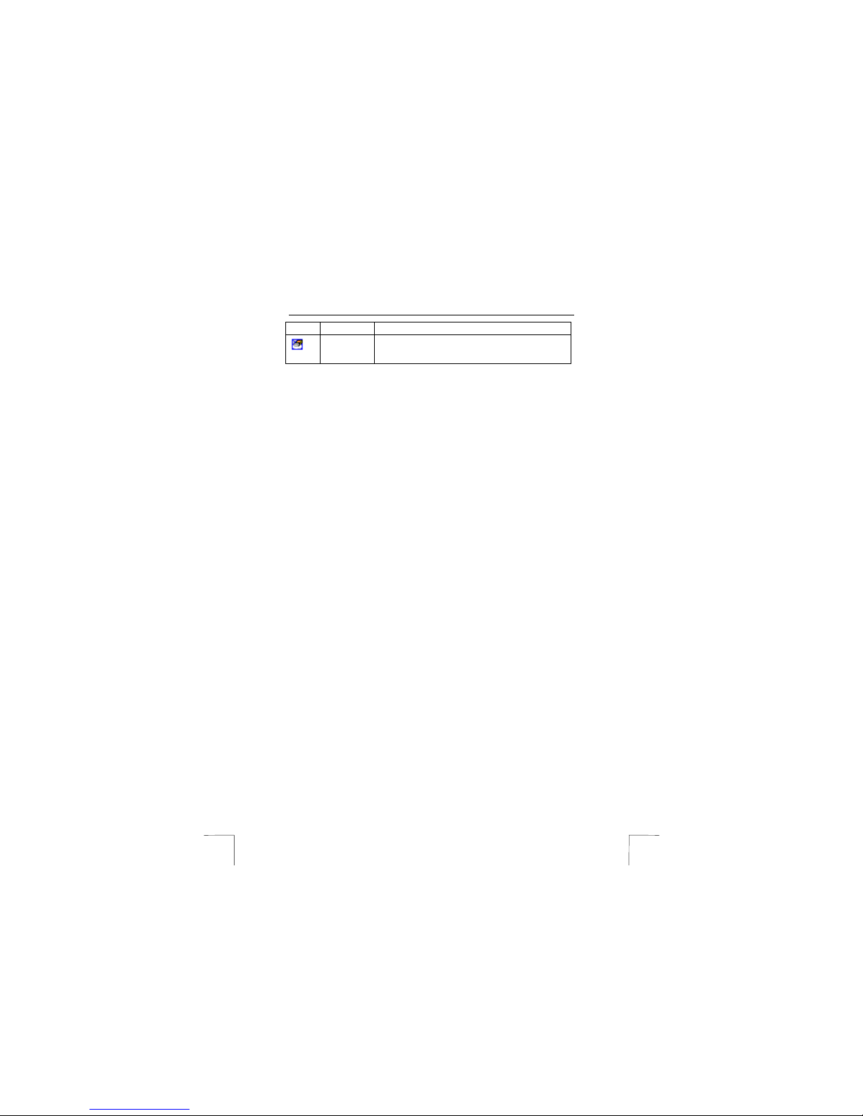
Furthermore, the Surveillance software carries the following functions:
•
Full Screen Mode
; view the screen at full screen size.
•
Trust Backup Software
; make a backup of your log files on your hard disk, CD-
R or ZIP media.
•
Trust Rep air Data Ba se Utility
; repair damaged files.
Consult the manual on the CD-ROM and the comprehensive manual for the
Surveillance Software for further information about the above functions.
4.1.1 Audio recording
In order to record sound by means of the audio connection of the Surveillance
Interface 801 USB, you first need to select the audio connection as a standard device
for audio recording in Windows, as follows:
1. Go to ‘Start – Settings – Configuration screen’.
2. Double-click the ‘Multimedia’ icon.
3. Go to the ‘Audio’ tab sheet and select the audio part of the Surveillance
Interface 801 USB as the preferred device for audio recording.
4. Click ‘Apply’ to apply the alterations.
4.2 Trust Remote View Software
Start up the external computer that the Trust Remote View Software has been
installed on. Go to ‘Start – Programs – Trust – Surveillance Interface 801’ and select
the option ‘Trust Remote View Software’ to start up this program on your external
system.
Note: The Surveillance software has to be activated and both the local
and the external computer must have an active Internet or
network connection.
The main screen of Remote View will appear. You can now make the connection to
the Surveillance Software. There are 3 options for making the connection:
4.2.1 Dial modem
Direct dial-in to the local computer with the Surveillance software. Make sure that the
Surveillance software checks the modem login.
1. In the Surveillance software go to ‘Remote – Login Setting’ and tick the option
‘Listen on Modem login’. See Figure 7.
2. Then, in the main screen, click the ‘Modem Login’ button.
3. In the Remote View software click the button ‘Connect’ and select ‘Dial
Modem’.
Note: The ‘Dial Modem’ function will only work with analogous modems.
In addition, the local modem must support the ’Modem Login’
function.
4. Enter the phone number with ‘Phone Dial’.
5. If necessary enter ‘Login Password’ and click ‘Make Call’.
Page 7

TRUST SURVEILLANCE INTERFACE 801 USB
7
UK
6. If the connection was made correctly, the camera picture will become visible in
the main screen of the Remote View Software. See Figure 9.
4.2.2 Intranet IPX
Establish a connection with the local computer via IPX intranet network. Make sure
that the Surveillance software checks the IPX intranet login.
1. In the Surveillance software go to ‘Remote – Login Setting’ and tick the option
‘Listen on Intranet login on IPX Protocol’. See Figure 7.
2. Then, in the main screen, click the ‘Network Login’ button and tick the option
‘Intranet Listen on IPX’.
3. In the Remote View software, click the ‘Connect’ button and select ‘Intranet
IPX’.
4. Click the ‘Locate Server’ button. The local computer is located in the network.
Click ‘OK’.
5. If necessary, enter ‘Login Password’ and click the ‘Login’ button.
6. If the connection was made correctly, the camera picture will become visible in
the main screen of the Remote View Software. See Figure 9.
4.2.3 Internet/Intranet TCP/IP
Establish a connection with the local computer via Internet or intranet TCP/IP. Make
sure that the Surveillance software checks the TCP/IP Internet/intranet login.
1. In the Surveillance go to ‘Remote – Login Setting’ and tick the option ‘Listen on
Intranet/Internet Login on TCP/IP Protocol’. See Figure 7.
2. Also tick the option ‘Assign IP Address’ and fill in your IP number.
Note: If your Internet connection goes via an ISP and you got an IP
address automatically, this will be easy to locate via ‘Start – Run’
after which you type ‘winipcfg’ and click ‘OK’. See Figure 8.
Then select ‘PPP Adapter’; the IP number will now be visible.
Each time you dial in t his number will be diff erent.
3. Now, in the main screen, click the ‘Network Login’ button and tick the option
‘Internet/Intranet Listen in on TCP/IP’.
4. In Remote View software click the ‘Connect’ button and select ‘Internet/Intranet
TCP/IP’.
5. Click ‘Locate Server’. The lo cal computer will be locat ed in the network. Click
‘OK’.
6. If necessary, enter the ‘Login Password’ and click ‘Login’. In case of a login via
the Internet, the dial-in screen of your modem will appear.
7. If the connection was made correctly, the camera picture will become visible in
the main screen of the Remote View Software. See Figure 9.
Consult the manual on the CD-ROM and the detailed help function of the Remote
View Software for further information about the above functions.
4.3 Trust IP Multicast Software
The Trust IP Multicast Software can only be used in an Intranet/LAN environment; it
won’t work via WAN/Internet.
If your network includes various computers that have the Trust Surveillance Software
with a camera installed, you can use the IP Multicast Software on an external
computer to log in on the same network, on a maximum of 10 computers
simultaneously. This allows you to switch between 10 different camera pictures.
Page 8

TRUST SURVEILLANCE INTERFACE 801 USB
8
Make sure that the Surveillance soft ware on all the relevant computers che cks the IP
Multicast login.
1. In the Surveillance software, go to ‘Remote – Login Setting’ and tick the option
‘Multicast Server’. See Figure 7.
2. Then, in the main screen, click the ‘Network Login’ button and tick the option
‘Multicast Server’.
3. Start up the IP Multicast Software and the external computer. Go to ‘Start –
Programs – Trust – Surveillance Interface 801’ and select the option ‘Trust IP
MultiCast Software’. The main screen will appear. See Figure 10.
4. Now click the ‘Search’ butto n. The IP Multicast software will search all
available Surveillance computers in the network and place them in the ‘Live’
menu.
5. In the ‘Live’ menu select the Surveillance computer you want to log into and
click the camera icon below the ‘Live’ button. If necessary, enter your
Password.
6. The camera picture of the selected Surve illance computer will appear in the
main screen.
Consult the manual on the CD-ROM and the detailed help function of the IP Multicast
Software for further information about the above functions.
Page 9

TRUST SURVEILLANCE INTERFACE 801 USB
9
UK
5 Troubleshooting
Problem Cause Possible solution
Driver could not be
located.
Place the CD-ROM in your
CD-ROM drive and enter
‘Driver’ for a location . See
section 3.1.
USB plug not connected
properly.
Connect the USB plug
properly.
USB-interface is not
installed.
There is an IRQ address
conflict with another USB
device.
Solve this problem via
‘device management’ in
Windows.
The camera has not been
connected.
Connect the camera.
Not power supply to the
camera.
Connect the camera to a
power outlet or switch it on.
The Sur veillance
software only
renders a black
picture.
Incorrect video standard. Check the video standard of
the camera and set it in the
Surveillance software. See
section 4.1.
Picture of the
connected camera
not found in the
Surveillan ce
software.
The camera in question
was not selected in the
software.
Select the camera. Se
section 4.1.
Unable to log in with
RemoteView software
on local computer.
IP address that was filled
in doesn’t match the IP
address of the local
computer.
Check the IP address with
your provider or run the
program ‘winipcfg’. Se e
section 4.2.3.
The password that was
filled in doesn’t match the
password of the local
computer.
Fill in the correct password
in the RemoteView and IP
Multicast software.
Error message ‘Login
incorrect’ appears in
the RemoteView
software or IP
Multicast software.
IP numbers do not
correspond.
Fill in the exact same IP
number in Surveillance and
RemoteView soft ware.
Picture are projected
in slow motion on the
external computer.
Internet connection is
slow.
Try again at a later time.
Harddisk is full.
The video recordings
take up too much space.
Regularly remove old
recordings by selecting the
‘Recycle’ option in the
‘Preference’ screen of the
Surveillance software.
After setting the
sensitivity, the
system records
Settings too sensitive. Use a less sensitive setting.
See section 4.1.
Page 10

TRUST SURVEILLANCE INTERFACE 801 USB
10
Problem Cause Possible solution
continuously.
Make sure the sensitivity of
the Surveillance software
has a lower setting when
using cordless systems.
Reposition the cordless
cameras or select a different
channel.
When using the Trust
100 series cordless
system, the alar m
goes off
continuously.
Interference in picture
because of RF
connection.
See troubleshooter for the
Trust 100 series cordless
devices.
Problem not listed
here.
FAQ update available
online.
Go to www.trust.com/12544
for FAQ.
Register your product via www.trust.com so that you are able to receive optimal
guarantee and service support such as up-to-date FAQ and the latest drivers. You will
also be automatically informed of developments to your product and of other Trust
products. And use the opportunity to win some spectacular prizes.
If you still have any prob lems after trying the se solutions, please co ntact one of the
Trust Customer Care Centres. You can find more information on the last page of this
manual. Please have the following information available: the article number (12544)
and a good description of what exactly fails to work, and when the problem occurs.
 Loading...