

TruPace E220 Owner's Manual
E 220 Elliptical Trainer
Owner’s Manual
Retain this owner’s manual for future reference
Read and follow all instructions in this owner’s manual

Page
Contents
1
General Information
2
Warnings
3
Power Requirements
4-10
Assembly Instructions
11-12
Getting Started
13-18
Computer Operation
19-20
Maintenance
21-22
Troubleshooting
23
Parts Diagram
24-27
Parts List
28
Exercise Warnings
29
Heart Rate Chart
30-33
Warm up / Stretching
34-35
Limited Warranty
Table of Contents

Thank you for choosing this elliptical trainer.
You have taken the first step to a healthier and more rewarding lifestyle.
This Elliptical is especially designed to give you reliable performance and enjoyable workouts in
the comforts of your home. Below you will find the features and benefits of your new Elliptical.
◇ Multiple level electronic magnetic resistance.
◇ Low impact exercise system
◇ Mobility wheels for easy moving and relocation.
◇ Hand contact heart-rate system to monitor cardio performance.
TECHNOLOGY DATA
Voltage
AC-110V 50/60Hz
Max weight
275 LBS.
Dimension
Unfolding: 64.8"L x 24.8"W x 46.3"H
Owner’s Manual 1
CAUTION:
Before beginning any exercise program always consult your physician. If you experience chest
pain, nausea, dizziness or shortness of breath, stop exercising and consult your physician before
continuing.

WARNING: To reduce the risk of burns, fire, electric shock, or injury to persons, read the
following important precautions and information before operating the Elliptical. It is the
responsibility of the owner to ensure that all users of this Elliptical are adequately informed of all
warnings and precautions.
●Use the Elliptical only as described in this manual.
●Place on a level surface, with 3 feet (1 m) of clearance behind it. To protect the floor or carpet
from damage, place a mat under the Elliptical.
●When choosing a location for the Elliptical be sure that the location and position permit access
to a plug.
●Keep the Elliptical indoors, away from moisture and dust. Do not put the Elliptical in a garage
or covered patio, or near water.
●Do not operate the Elliptical where aerosol products are used or where oxygen is being
administered.
●Keep children under the age of 12 and pets away from the Elliptical at all times.
●The Elliptical should not be used by persons weighing more than 275LBS.
●Never allow more than one person on the Elliptical at a time. Wear appropriate exercise
clothing when using the Elliptical. Do not wear loose clothing that could become caught in the
Elliptical. Athletic support clothes are recommended for both men and women. Always wear
athletic shoes. Never use the Elliptical with bare feet, wearing only stockings, or in sandals.
●When connecting the power cord, plug the power cord into a grounded circuit.
●Always examine your Elliptical before using to ensure all parts are in working order.
●Never insert any object or body parts into any opening.
●Always follow the safety information regarding plugging in your Elliptical.
●Keep the power cord away from the wheels and do not run the power cord underneath your
Elliptical. Do not operate the Elliptical with a damaged or frayed power cord.
●Always unplug the Elliptical before cleaning and/or servicing. Service to your Elliptical should
only be performed by an authorized service representative, unless authorized and/or instructed
by the manufacturer. Failure to follow these instructions will void the Elliptical warranty.
Owner’s Manual 2

Power Requirements:
IMPROPER CONNECTION OF THE EQUIPMENT GROUNDING CONNECTOR CAN
RESULT IN THE RISK OF AN ELECTRIC SHOCK. CHECK WITH A QUALIFIED
ELECTRICIAN OR SERVICE MAN IF YOU ARE IN DOUBT AS TO WHETHER THE
PRODUCT IS PROPERLY GROUNDED. DO NOT MODIFY THE PLUG PROVIDED WITH
THE PRODUCT, IF IT WILL NOT FIT THE OUTLET; HAVE A PROPER OUTLET INSTALLED
BY A QUALIFIED ELECTRICIAN.
This Elliptical can be seriously damaged by sudden voltage changes in your home’s electrical
power. Voltage spikes, surges and noise interference can result from weather conditions or
from other appliances being turned on or off. To reduce the possibility of Elliptical damage,
always use a surge protector (not included) with your Elliptical.
Surge protectors can be purchased at most hardware stores. The manufacturer recommends
a single outlet surge protector with a UL 1449 rating as a Transient Voltage Surge Suppressor
(TVSS) with a UL suppressed voltage rating of 400V or less and an electrical rating 110VAC, 15
amps.
This Elliptical must be grounded to reduce the risk of electrical shock. Grounding provides a
path of least resistance for electric current, should the Elliptical malfunction. This Elliptical is
equipped with an electrical cord that has an equipment-grounding conductor and a grounding
plug. Always plug the power cord into a surge protector, and plug the surge protector into an
appropriate outlet that is properly installed and grounded in accordance with all local codes and
ordinances.
This product is for use on a nominal 110-volt circuit
Owner’s Manual 3
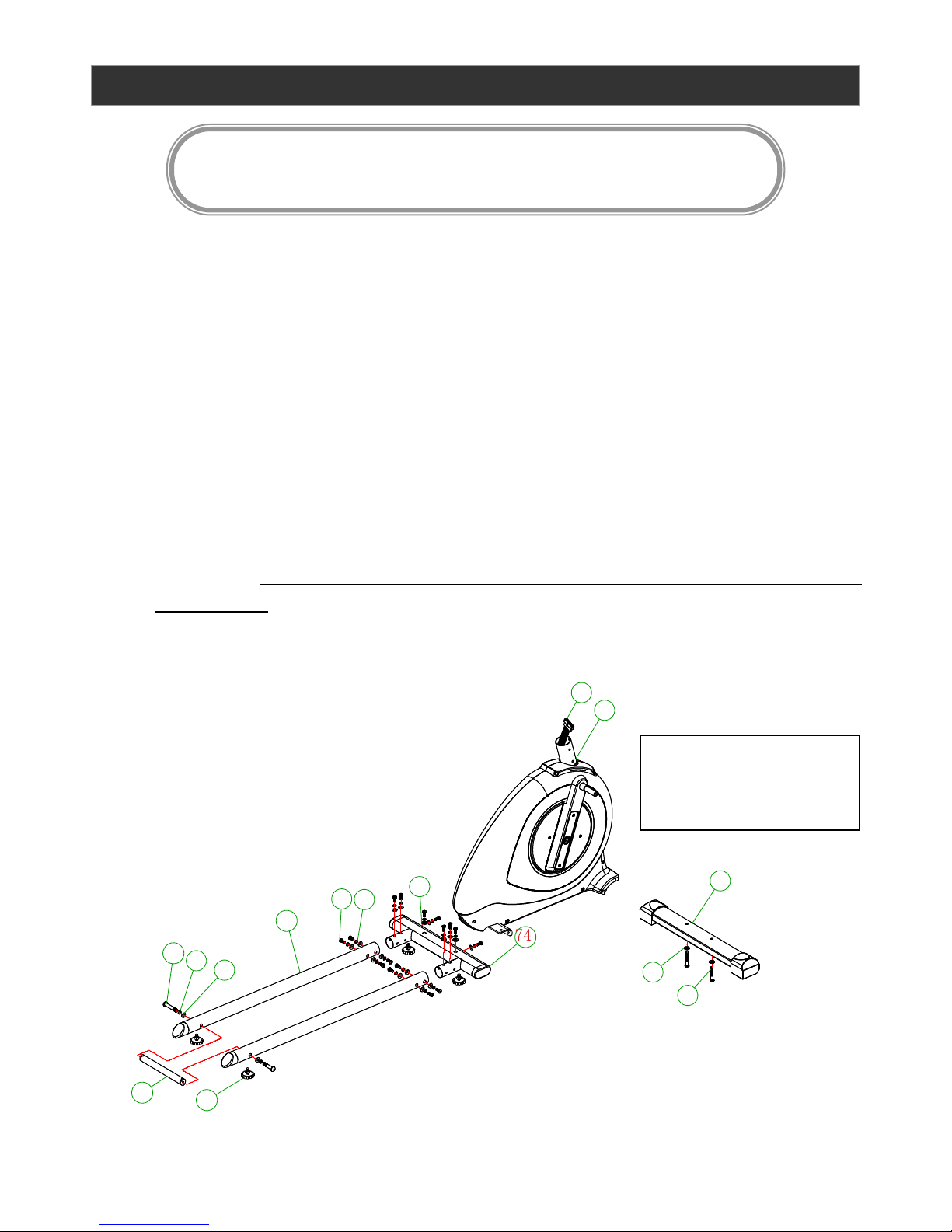
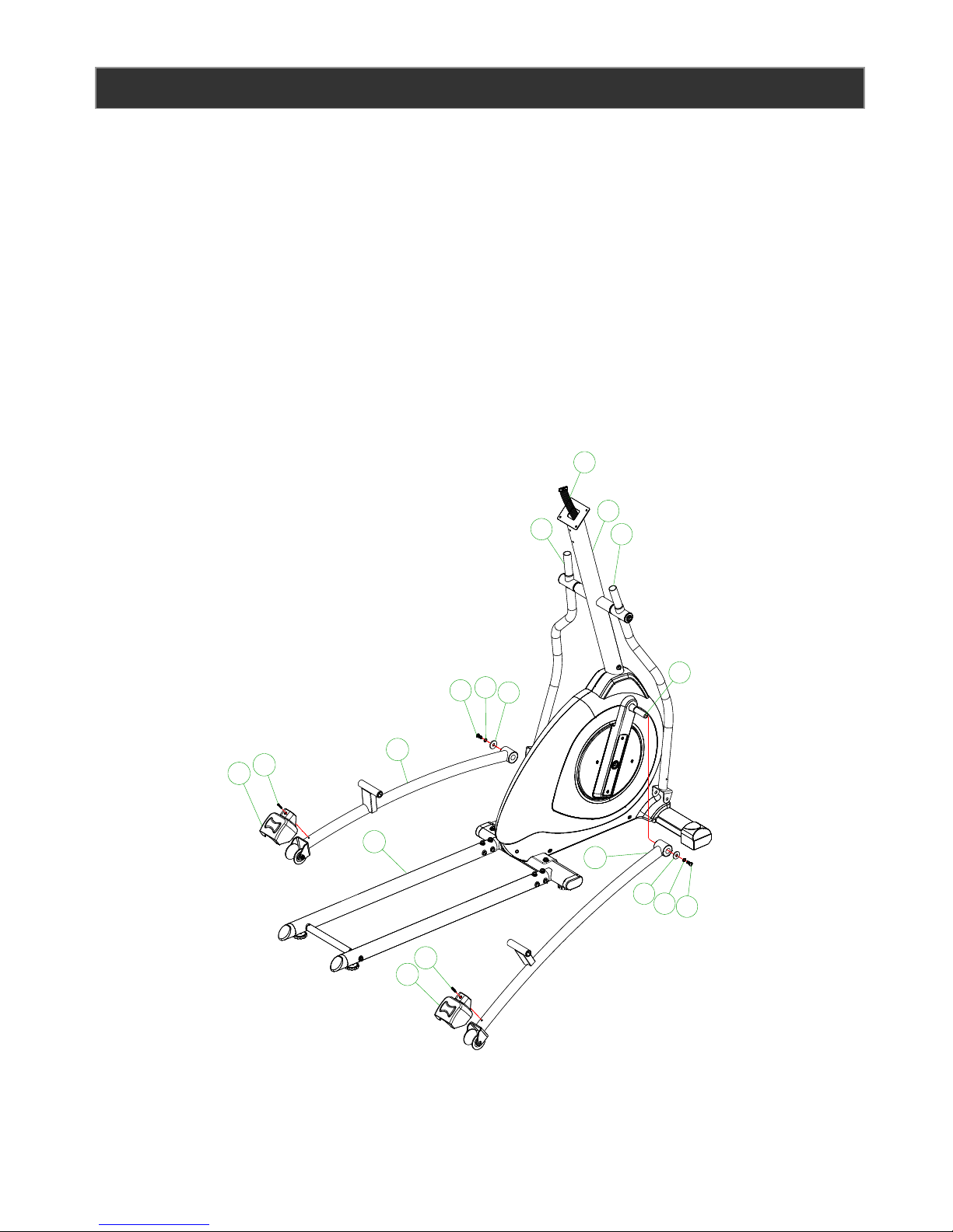
ASSEMBLY INSTRUCTIONS
Step 1:
A. Place the product in the area it will be used.
a. Note: Elliptical must be placed on a level surface
B. Remove the Elliptical from the packaging
C. Attach the front stabilizer (35) to the main frame (47) using 2 x M8*55mm Allen bolts (33)
and 2 x Ф8*19*1.5mm flat washer (34).
D. Attach the slider tubes (104) to the rear stabilizer (74) using 12 x M8*20mm Allen bolts
(17), 12 x Ф8 spring washers (20), and 12 x Ф8*19*1.5t curved washers (16)
E. Attach the connecting tube (96) to the sliding tube (104) using 2 x M8*70mm Allen Bolts
(93), 2 x Ф8 spring washers (20), and 2 x Ф8*19*1.5t curved washers (16)
F. Attach the rear stabilizer (74) to the main frame (47) using 4x M8*20mm (17), 4 x Ф8
spring washers (20), 2 x Ф8*19*1.5t curved washers (16), and 2 x Ф8*19*1.5mm flat
washer (34). Note: the flat washers are used on the bolts attached through the top of the
rear stabilizer.
G. Tighten all bolts now.
Owner’s Manual 4
Caution Pinch point. Do not
place your hands between
the frame components
93
20
16
104
96
94
17
34
20
35
34
33
47
48
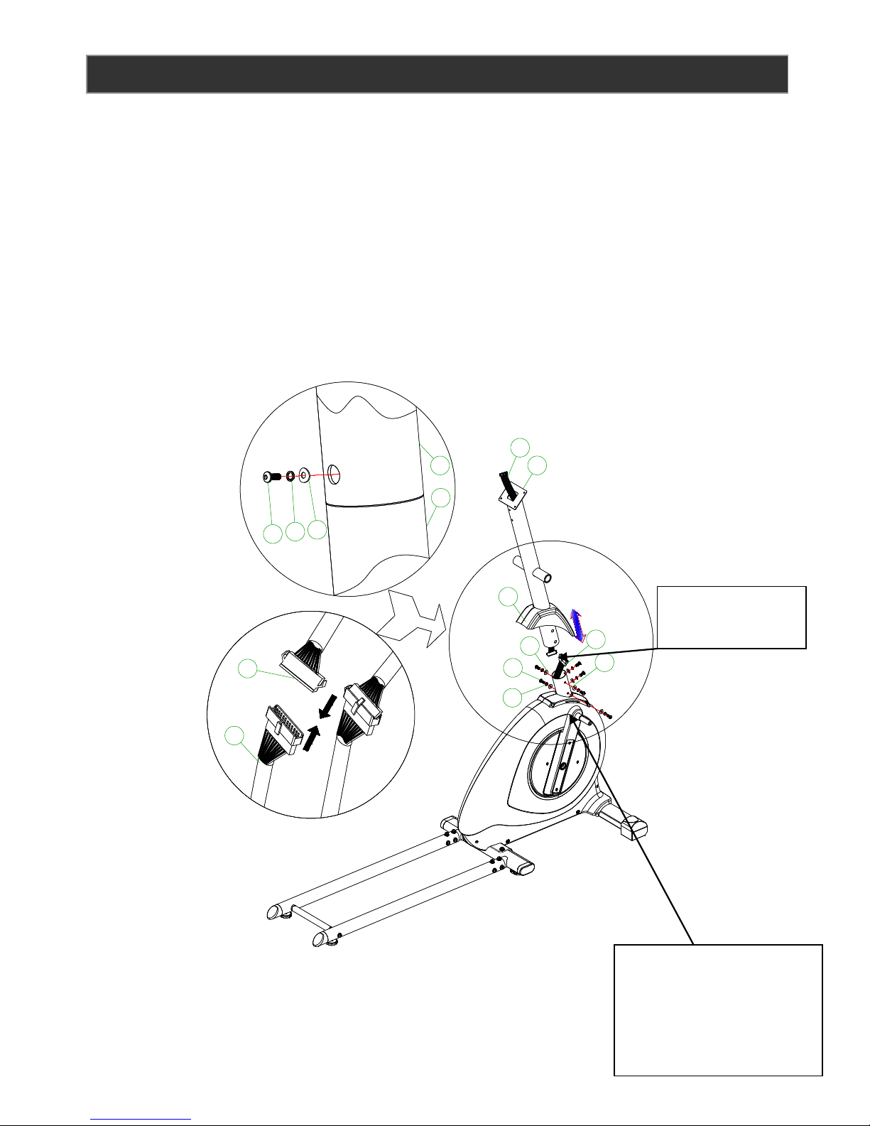
Step 2:
A. Slide the handlebar post cover (32) onto the handlebar post (49).
B. Connect the upper computer cable (3) with the lower computer cable (48) put the
excess cable in to the handlebar post.
C. Insert the handle par post (49) into the main frame (47), screw the lower 3 x M8*20mm
Allen bolt (17), 3 x Ф8 spring washers (20), 3 x Ф8*19*1.5t curved washers (16). Aline
the handlebar post (49) and tighten the bolts. Slide down the handlebar post cover (32)
onto the handlebar post (49), then tighten the upper 3 x M8*20mm Allen bolt (17), 3 x
Ф8 spring washers (20), 3 x Ф8*19*1.5t curved washers (16).
Owner’s Manual 5
20
16
17
48
3
3
49
47
49
47
17
20
16
48
32
Handlebar post
cover
Caution: Do not pinch the
computer wires between
the handlebar post and the
main frame during
assembly
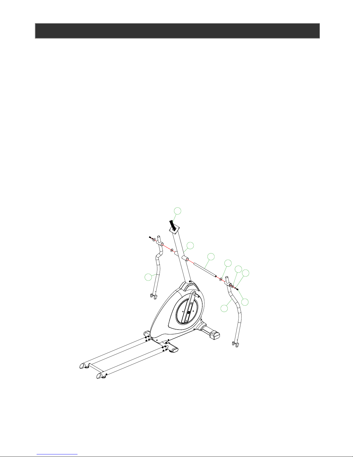
Step 3:
A. Slide 1 x Ф19.5*38*0.5mm (15) on to each side of the rotation rod (14) prior to attaching
the lower handlebars (44L & 44R)
B. Insert the rotation rod (14) into the handlebar post (49).
C. Attach the lower handlebars (44L) and (44R) onto the rotation rod (14) Note: Be certain
the correct handlebars are attached to the correct side of the post before
securing.
D. Secure the lower handlebars, using 2x M8*20 Locking Allen bolt (9), 2 x Ф8 spring
washers (20), and 2 x Ф8.5*36*3tmm flat washer (19).
E. Tighten all bolts now
Owner’s Manual 6
3
49
44L
44R
20
9
15
14
19
Step 4:
A. Attach the left pedal arm (71L) the left side crank (60)
B. Secure the left pedal arm to the crank by using 1 x M8*20 Locking Allen bolt (9), 1 x Ф8
spring washers (20), and 1 x Ф8.5*36*3tmm flat washer (19).
C. Attach the decorative cover (92) on to the left pedal arm by using 1 x M5*15 round head
screws (36)
D. Place the left pedal arm on to the slider tube.
E. Repeat the process above for the right side.
F. Tighten all bolts now.
Owner’s Manual 7
19
44R
44L
3
49
92
92
71R
36
36
71L
9
20
19
9
20
60
104

Step 5:
A. Attach the left pedal connecting to tube (69L) to the left lower handlebar (44L) by using 1
x M10*78mm Allen bolt (68), 1x Ф10*19*2t mm flat washer (53), and 1x M10 nut (75).
B. Attach the left pedal connecting tube (69L) to the left pedal arm (71L) by using 1 x Fixing
plate, 3 x M8*20mm Allen bolt (17), 3 x Ф8 spring washers (20), 3 x Ф8*19*1.5mm flat
washer (34).
C. Tighten all bolts now.
D. Attach the decorative cover (54L&R) to the lower handlebar (44L) by using 2 x M5*15
round head screw (36)
E. Repeat the process above for the right side
F. Attach the stationary handlebar (13) to the handlebar post (49) by using 2 x M8*20
Locking Allen bolts (9) and 2 x Ф8*19*1.5t curved washers (16). Tighten bolts now
G. Insert the left upper handlebar (1L) into the left lower handlebar (44L) and secure by
using 2 x M8*20mm Allen bolt (17), 2 x Ф8 spring washers (20), 2 x Ф8*19*1.5t curved
washers (16).
H. Repeat the process above for the right side
I. Tighten all bolts now.
Owner’s Manual 8
16
17
69R
69L
69R
69L
69L
71L
71L
102
20
34
17
44L
44R
44R
54L
54R
36
68
53
75
9
16
13
49
49
13
71R
20
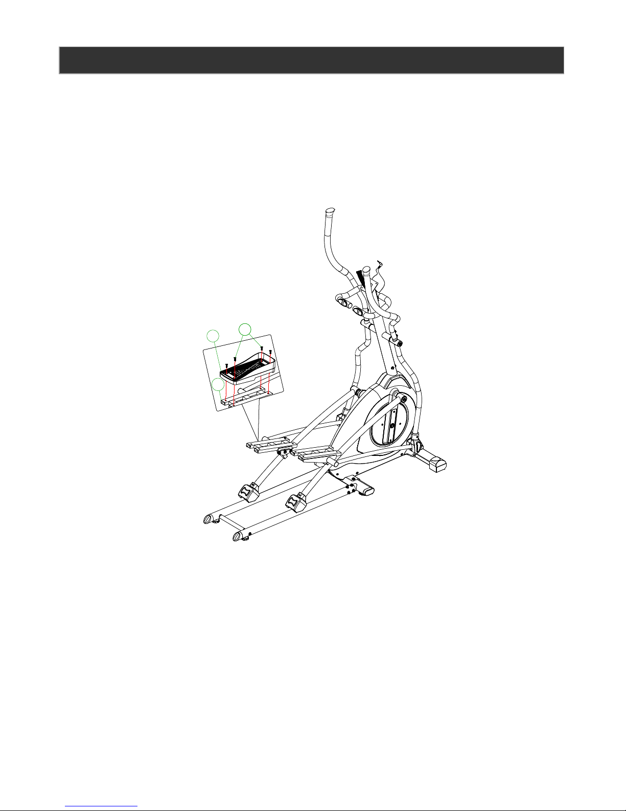
Step 6:
A. Attach the left pedal (67L) to the left pedal connecting tube (69L) by using 4 x M8*20mm
Allen bolts (66)
Owner’s Manual 9
6666
69L
67L
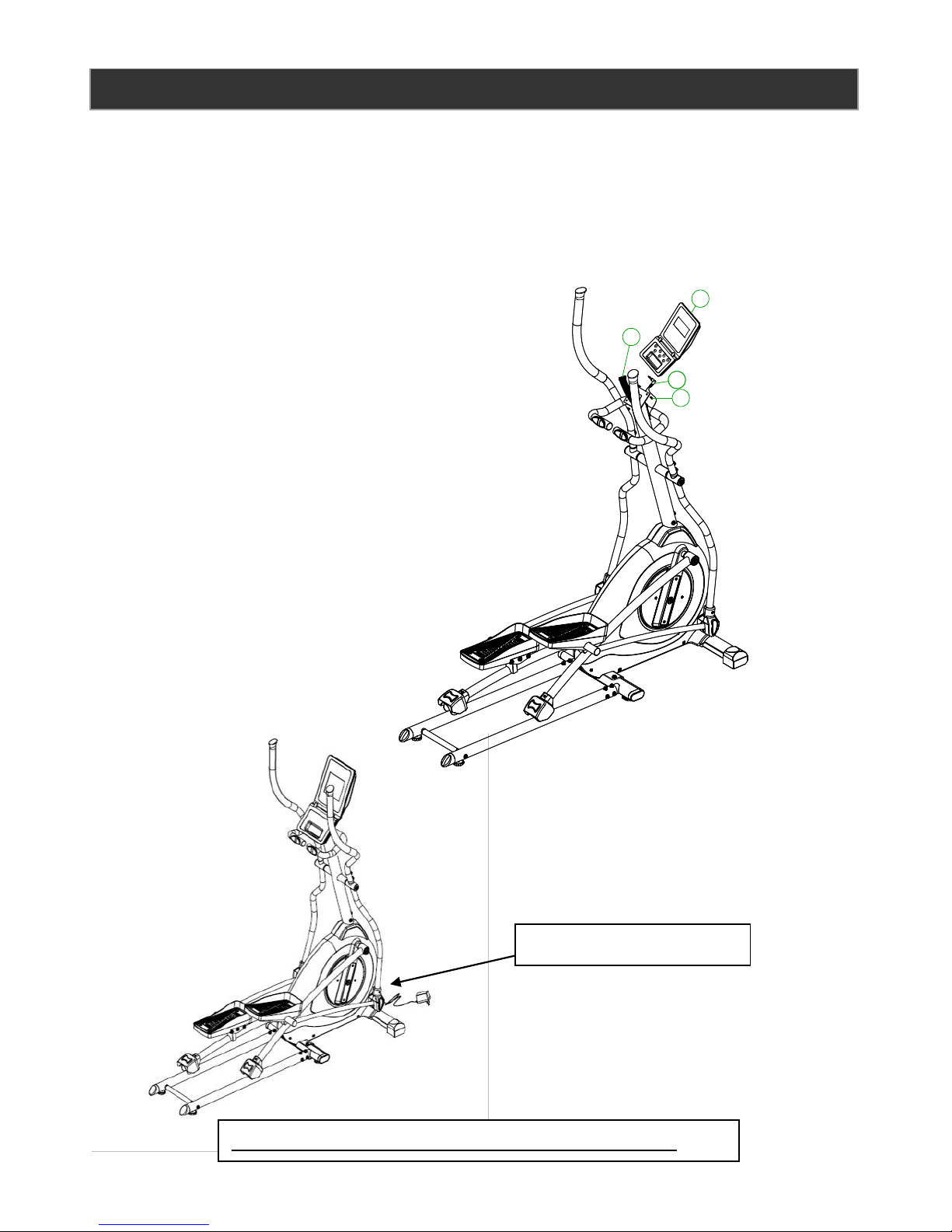
Step 7:
A. Remove the 4 console screws (2) from the back of the computer console.
B. Connect the upper computer cable (3) to the computer console cable (4)
Note: put the excess wire in to the handlebar post
C. Attach the computer console (4) to the handlebar post (49) by using the 4 screws (2)
removed from the console.
D. Tighten all bolts now.
Congratulations your Elliptical is now ready to use.
Plug in the power adaptor
Owner’s Manual 10
4
8
2
3
 Loading...