


DC Voltage measurement adapters for DPM 951 and DPM 952
DMDV-952-ADP for DPM 952-R DMDV-951-ADP for DPM 951-R
Switches 1 - 4 = Voltage range
configuration
Switches 5 - 8 = Decimal
1 234
1 = Power Supply 0V Input
2 = Power Supply +5V DC Input
3= Voltage Measuring 0V Input
4 =Voltage Measuring + V Input
point
Measured Voltage input range Configuration
– –
(
– = Switch DOWN (off )
– –
Switches - 1 2 3 4
Voltage Range
0 - 200mV •– ––
0 - 2V –• ––
0 - 20V –– •–
1234
Switches 1 - 4 = Decimal
point configuration
Decimal Point Configuration
• •
• = Switch UP (on ))
• •
Switches - 5 6 7 8 (on DMDV 952)
Switches - 1 2 3 4 (on DMDV 951)
1999 –– – –
199.9 –• – –
19.99 –– • –
0 - 200V –– –•
1.999 –– – •
Technical Data
Minimum Typical Maximum Units
Accuracy (±1 digit) ±2%
Linearity ±1 digit
Operating Temperature 0 50 °C
Sample Rate 3 Per second
Instructions for fitting Voltage measurement adapter to DPM 951 or DPM
Configure DPM 951 or DPM 952 module for supply voltage, and annunciators. Configure anunciators as required,(mV, V etc) refer
to DPM 951/ 952 instructions. Configure the module for a 5V supply - DPM 952 -solder links 2, 3, 4, and 6 on rear of PCB (leave
link 5 unsoldered) - DPM951 - solder links 4 and 6 on rear of PCB (leave link 5 unsoldered).
Note configuration of the supply voltage is necessary for adapters DMDV-951-ADP and DMDV-952-ADP. Complete Voltmeter kits
DMDV-951 and DMDV-952 have the supply voltage links factory pre-configured.
Annunciator
Configuration
(Rear of DPM 952) (Rear of DPM 951)
Annunciator
Configuration
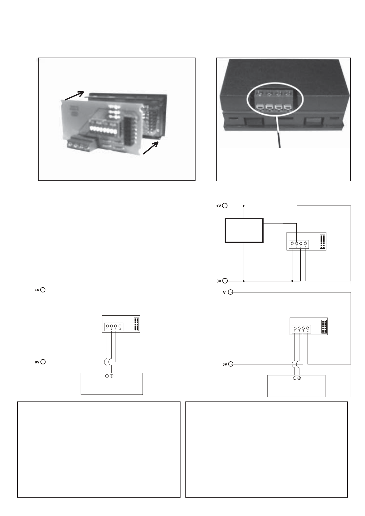
1) Fit the adapter module onto the rear of the DPM 951 or DPM 952 (depending on the adapter module). Configure the Voltage
Measurement input Selection switches for the appropriate range, and configure the Decimal point selection switches. Fit the rear case
as shown below.
Fit adapter module onto the meter
Cut out plastic from the rear case
to allow access to the connector
and fit onto the rear of the
DPM 95/ adapter assembly.
2)
Connect the power supply 0V output to terminal 1, connect the power
supply +5V DC output to terminal 2.
Connect the measured voltage 0V output to terminal 3, and the +VDC
measured voltage output to terminal 4. It is possible to measure
negative voltage on terminal 4. Terminal 3 must be connected to 0V,
not
a -V or +V voltage.
Note, Do not apply a higher voltage than the unit has been configured for.
If a higher voltage is applied this may result in damage.
Connect the unit as shown in any of the three diagrams shown.
5V DC
Regulator
5V DC
Power Supply
Trumeter Company Ltd, Milltown Street, Radcliffe, Manchester
M26 1NX, England
Tel: (44) (0)161 724 6311 Fax: (44) (0)161 724 9455
e-mail: sales.uk@trumeter.com
Trumeter Ireland, PO Box 5050, Drogheda, Ireland
Tel: (353) (0)41 983 7755 Fax: (353) (0)41 983 7753
e-mail:sales.ireland@trumeter.com
Trumeter Company Inc.,1020 North West 6 Street, Deerfield Beach
Florida 33442, U.S.A.
Tel: (1) 954 725 6699 Fax: (1) 954 725 5599
email: sales.usa@trumeter.com
5V DC
Power Supply
Trumeter Canada, 190 Brittania Road East, Unit 5, Mississauga,
Ontario, L4Z 1W6, Canada
Tel (1) 905 890 0622 Fax: (1) 905 890 7994
email: sales.canada@trumeter.com
Trumeter Deutschland, Postfach 1215, D-71141, Steinenbronn,
Deutschland
Tel: (49) (0) 7157 20801 Fax: (49) (0) 7157 20813
email: verkauf.deutschland@trumeter.com
Trumeter, 99 rue Parmentier, BP 304, 59666 Villeneuve d’Ascq
Cedex, France
Tel: (33) (0) 3 20 59 16 26 Fax: (33) (0) 3 20 59 16 27
email: ventes.france@trumeter.com
 Loading...