

Trumeter APM-MAX-M23-PL-4B, APM-MAX-M23-PL-4R, APM-MAX-M23-NL-4R, APM-MAX-M23-NL-4B, APM-MAX-M23-NU-4B User manual
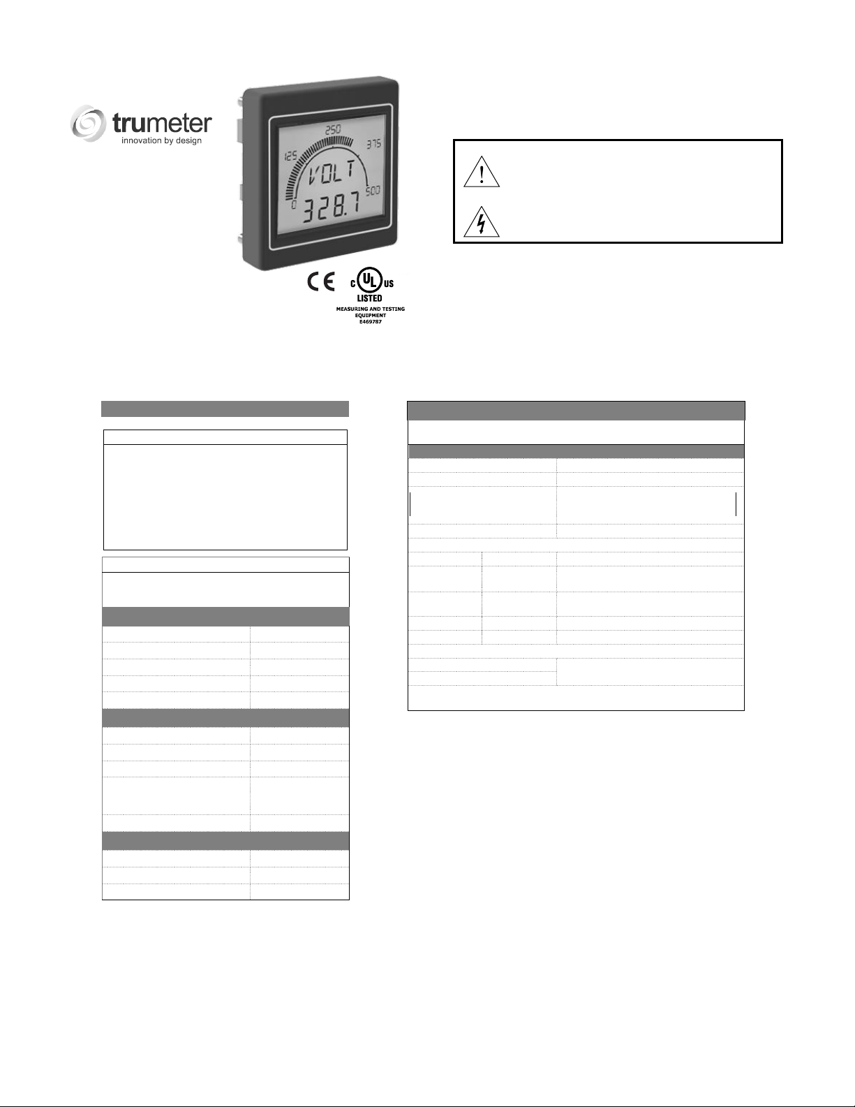
APM
MAX-M23
Before installation, read the Safety Warnings
overleaf.
CAUTION: Risk of Danger. Read complete instructions
prior to installation and operation of the unit
CAUTION: Risk of electric shock
Operating specification
Intended Use: The APM has been specifically
designed for engineers requiring an effective way to
monitor and display data. The APM accepts a range of
electrical inputs (depending on the model) and
displays the data on its integrated multi-format display.
The APM has been designed for installation into
electrical cabinets or display panels. The units come
as standard with two digital outputs and one serial
output.
The digital readout will still show the actual voltage even if
the bar graph is out of range.
Measurement Range
Voltage / Frequency 0–10V DC
Shunt 0–500mV DC
Current Input 0–80mA
Frequency (min. voltage 0.5V AC) 0–400Hz
DC Power Measurement Watts
Measurement Accuracy
DC 0.5%
Frequency 0.1%
Power Measurement 0.5%
Isolation Reinforced
Measurement Category CATII
Impedance
Voltage / Frequency 2 MΩ
Shunt 10 MΩ
Current Input 15Ω
4KV @ 1 Sec
3KV @ 1 min
Communication
Modbus Configured Parameters (Trumeter configurator required): Only function
code 4 – read input register supported.
Slave ID 0 to 255
Baud Rate 4800 to 192000
Stop Bits and Parity 2 stop bits no parity
Communications Enable / Disable
Modbus Registers
Address Variable Type Description
1-2 32bit Float
3-4 32bit Float
5 1 Byte Alarm 1
6 1 Byte Alarm 2
TCP/IP Parameters
IP Address
Subnet Mask
Gateway, DNS1, DNS2, Hostname, Interface Name, Modbus Port Address,
Modbus Timeout Period.
Parameter RTU
1 stop bit even parity
1 stop bit odd parity
Displayed Value
(after configuration)
SI measured unit
(before configuration)
Only adjustable if DHCP disabled
Find Quality Products Online at: sales@GlobalTestSupply.com
www.GlobalTestSupply.com

Wiring Diagrams
DC VOLTAGE MEASUREMENT | AC FREQUENCY MEASUREMENT DC CURRENT MEASUREMENT USING SHUNT (500mV MAX)
GND
AOUT
DOUT1
DOUT2
RS485-A
RS485-B
RELAY OUTPUT (ACTIVATED BY DOUT1) 4-20mA ANALOG OUTPUT
NOTE: Relay requires
protection diode
VOLTS / FREQ
CURRENT
PSU
D+V
I+V
~
~
GND
+V
-V
-V
N
L
FUSE
INPU T
+-
-
+
N
L
PSU
GND
AOUT
DOUT1
DOUT2
RS485-A
RS485-B
-
+V
-V
VOLTS / FREQ
D+V
I+V
-V
CURRENT
N
~
PSU
L
~
+
DC REL AY SUPP LY
AOUT
DOUT1
DOUT2
RS485-A
RS485-B
Optional connection
to system ground
+V
-V
D+V
I+V
-V
CURRENT VOLTS / FREQ
N
~
PSU
L
~
FUSE
L N
- +
PSU SUPPLY
-
+
SHUNT
GND
AOUT
DOUT1
DOUT2
RS485-A
RS485-B
- +
+V
-V
VOLTS / FREQ
D+V
I+V
-V
CURRENT
~
PSU
~
LOAD
N
L
4-20 mA output
Find Quality Products Online at: sales@GlobalTestSupply.com
www.GlobalTestSupply.com
Safety Warnings
WARNING: INSTALLATION AND MAINTENANCE MUST BE CARRIED
OUT BY SUITABLY QUALIFIED AND COMPETENT PERSONEL ONLY.
HAZARDOUS VOLTAGES MAY BE PRESENT ON THE CONNECTION
TERMINALS.
• Install this product in accordance with local regulations, codes and instructions.
• An external fuse must be fitted in-line with the PSU. Recommended fuse: 0.5A
Type F with a breaking capacity of 35A or greater. Fuse voltage rating must be
greater than the maximum supply voltage.
• All conductors carrying hazardous voltage must have external switching or
disconnect mechanisms fitted that provide at least 3mm of contact separation
in all poles. The switch must be suitably located; easily reached and marked
as the disconnecting device.
• Signal cables connected to this device must not exceed 30 metres long.
• If signal cables are routed outside the building, install extra surge-protection
devices.
• Current measurement input, USB and all outputs: Observe maximum allowable
voltages. All circuits connected to these connectors must be limited-energy and
insulated by double/reinforced insulation from mains voltages according to IEC
61010-1:2010
Failure to install or operate the unit in accordance with the
above requirements may impair the electrical safety of the
unit.
Voltage measurements: An external UL recognized or listed
overcurrent protection device (fuse or circuit breaker) must
be fitted in-line with the voltage lead. Recommended fuse:
0.5A Type F with a breaking capacity of 35A or greater. Fuse
voltage rating must be greater than the maximum voltage that
will be applied to the meter.
• Before cleaning, inspection or maintenance, isolate all power sources to the unit.
• There are no user-serviceable parts inside this unit. Never open the case.
• Inspect all external wiring connections at regular intervals. Replace any
damaged wiring and tighten any loose connections.
• To clean the unit, use a dry cloth to wipe the casing.
• Take great care connecting the supply. If you connect power to the wrong
terminals, it may destroy the unit.
INSTALLATION
MAINTENANCE
Software
You need the software to configure the setpoints and outputs.
Size
Specification
Environment
Relative Humidity (non-condensing) - Continuous 0 – 85 %
Relative Humidity (non-condensing) - Intermittent 0 – 95 %
Voltage 100-240V AC 50-60Hz
Number of digits - Starburst 4
Max voltage (open collector outputs) 34
Accuracy 0.50 %
Accuracy 0.50 %
Type Screw Terminals
APM
Getting started & safety guide
IP65 Gasket
Mounting Kit
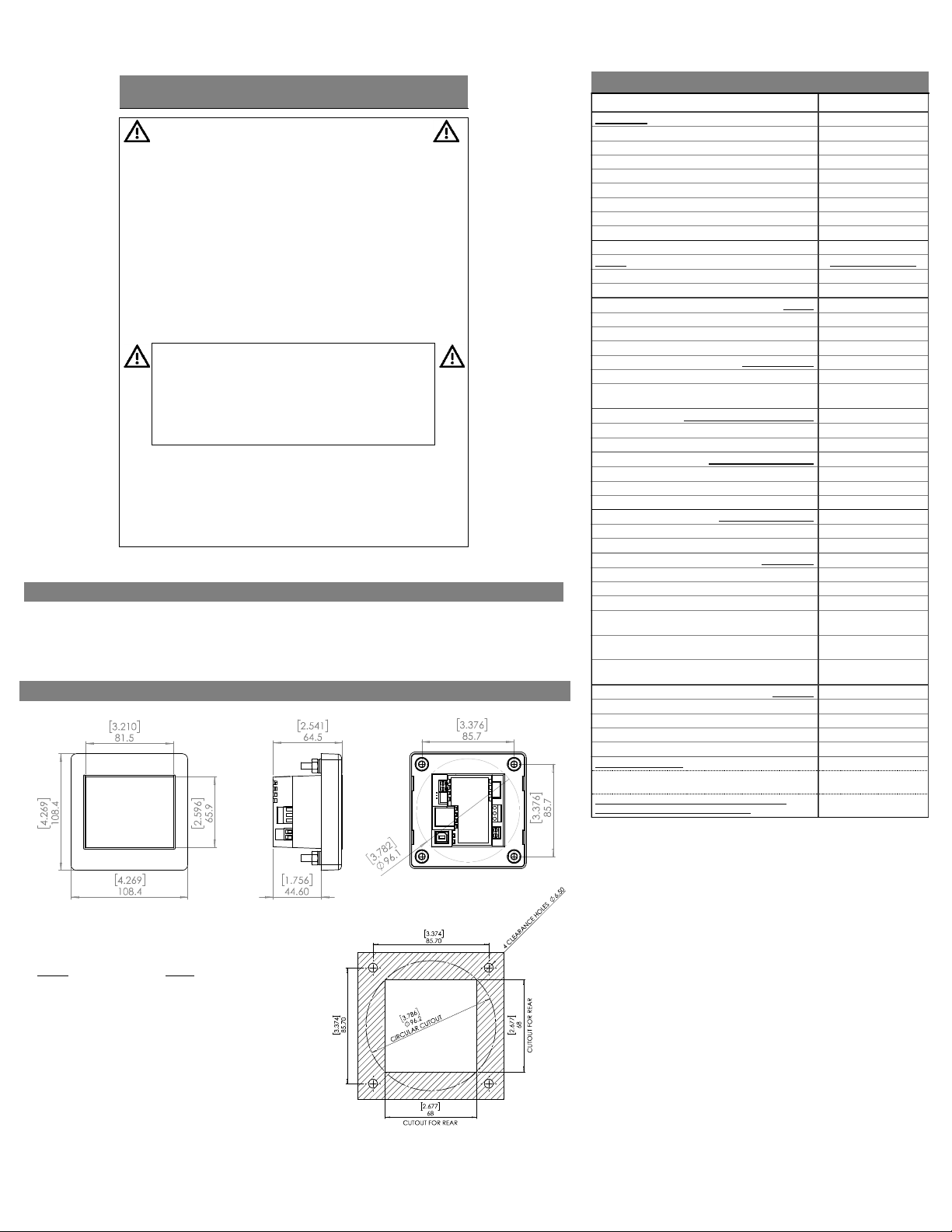
Dimensions & Weight
Panel Cut-out: 68 x 68 mm (2.68 in) square; 106mm (4.00 in)
round +0.7 -0 mm (0.02 in). Max. panel thickness: 11.0 mm.
Depth behind panel inside front: 55mm (2.17in) incl.
external connections. Weight: 340 grams.
Temperature - operating –10 to +60 deg C
Temperature - storage –40 to +70 deg C
Altitude 2000 metres
Overvoltage category (IEC664) II
Pollution Degree (IEC664) 2
IP rating (from the front) IP65
Power Supply
Max Power 5W
Isolation 4.2KVrms, 5mA 1 min
Display
Number of digits – 7 Segment 4
Number of bar-graph segments 60
Backlight colours RGBW
LCD Positive or negative
Viewing angle +/-70° Horizontal
Open Collector Sinking Outputs
Max current (open collector outputs) 500 mA
4-20 mA Analogue Output
Max Load 240 Ω
Resolution 0.02 mA
0-10V Analogue Output
Resolution 0.013V
Connections
Wire type Solid or Stranded
Min. cable temperature rating 70ºC (158ºF)
Wire strip length 6.5mm to 7mm
Wire gauge 0.8mm² - 3.3mm²
Torque 0.5-0.6Nm
In the Box
VALUE
+/-70° Vertical
VDC
(0.26” to 0.28”)
(18AWG to 12AWG)
(4.42-5.31 lbf-in)
Square: 68 x 68mm (2.68in) Round: 96.2 mm (3.79in) [+0.7 -0mm]
Size of the
Find Quality Products Online at: sales@GlobalTestSupply.com
cutout in the panel:
www.GlobalTestSupply.com
 Loading...