

Page 1
Page 2

Operating instructions
Electronic display counter
CODIX 52U
1.1 Safety instructions and warnings
Only use this display
– in a way according to its intended
purpose
– if its technical condition is perfect
– adhering to the operating
instructions and the general
safety instructions.
1.2 General safety instructions
1. Before carrying out any installation or maintenance work, make sure that the power supply
of the digital display is switched off.
2. Only use this digital display in a way according
to its intended purpose: If its technical condition is perfect. Adhering to the operating
instructions and the g eneral safety instructions.
3. Adhere to country or user specific regulations.
4. The digital display is not intended for use in
areas with risks of explosion and in the branches excluded by the standard EN 61010 Part 1.
5. The digital display shall only operated if it has
been correctly mounted in a panel, in accordance with the chapter “Main technical features”.
1.3 Use according to the intended purpose
The digital display may be used only as a panelmounted device. Applications of this product may
be found in industrial processes and controls, in
manufacturing lines for the metal, wood, plastics,
paper, glass, textile and other processing industries. Over-voltages at the terminals of the digital
display must be kept within the limits in Category II
If the digital display is used to monitor machines
or processes in which, in case of a failure of the
device or an error made by the operator, there
might be risks of damaging the machine or causing accidents to the operators, it is your responsibility to take appropriate safety measures.
1.4 Description
CODIX 52U is a multipurpose device. Depend-
ing on the pr ogrammed basic function, the
device operates like
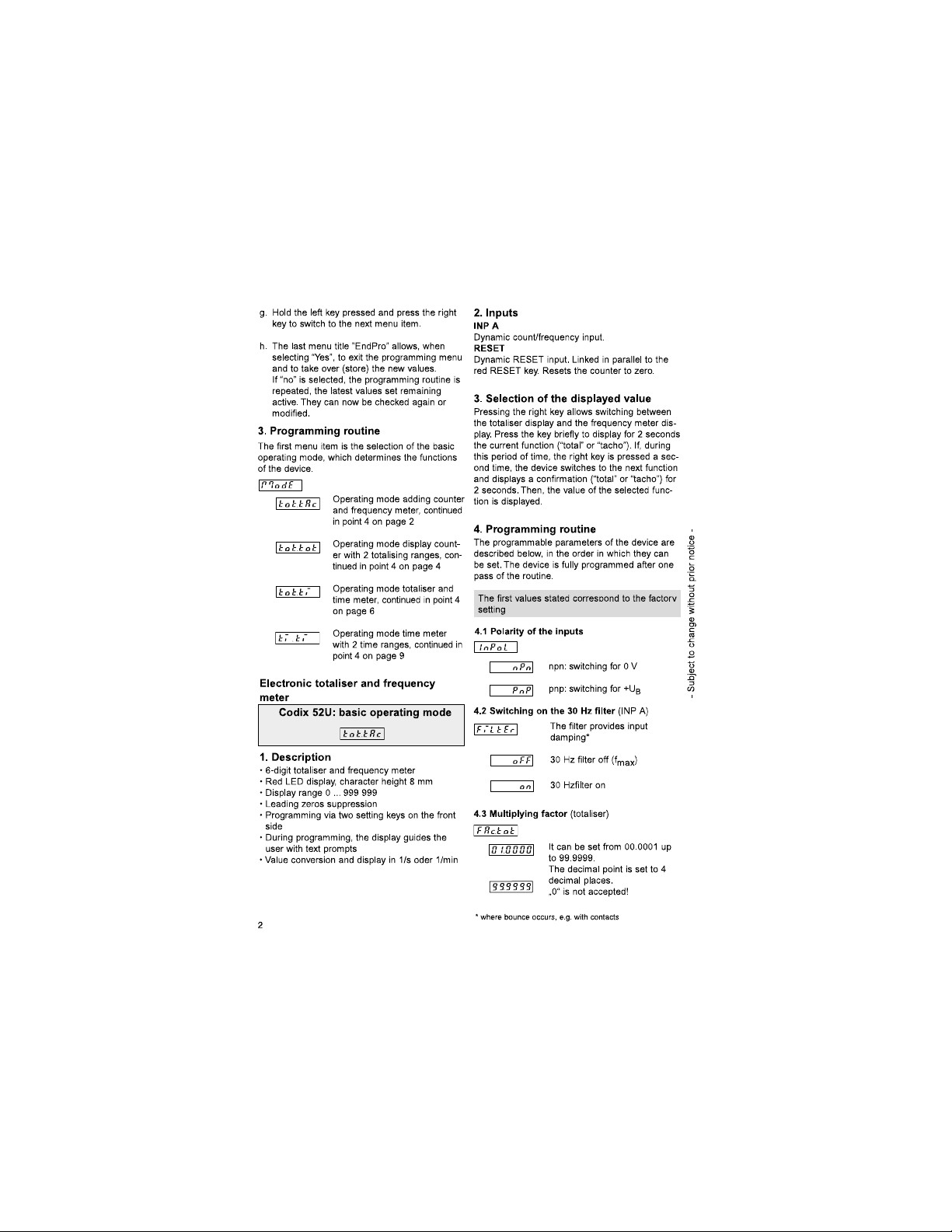
• an electronic totaliser and frequency meter
(see page 2)
• an electronic display counter with
2 totalising ranges (see page 4)
• an electronic totaliser and time meter
(see page 6)
• an electronic time meter with 2 time ranges
(see page 9)
2. Setting of the operating parameters
a. Press both front side keys keys and switch
on the supply voltage or, if the supply voltage
is already on, press both keys simultaneously
during 5 s.
b. The display shows
c. After releasing the keys, the display shows
c1. Hold the left key pressed an d press the right
key to leave the programming operation.
c2. Press the right key to switch to
d. Hold the left key pressed an d press the right
key to switch to the first parameter.
e. After releasing the keys, the display alter nates
between the menu title and the current menu
item setting. After pressing any key, only the
menu item setting is displayed.
f. Pressing the right key, the menu item setting
will be switched to the next value. If figures
are to be input (e.g. when setting the scaling
factor), select first the decade using the l eft
key, and then set the value using the right key.
Find Quality Products Online at: [email protected]
www.GlobalTestSupply.com
Page 3
Page 4
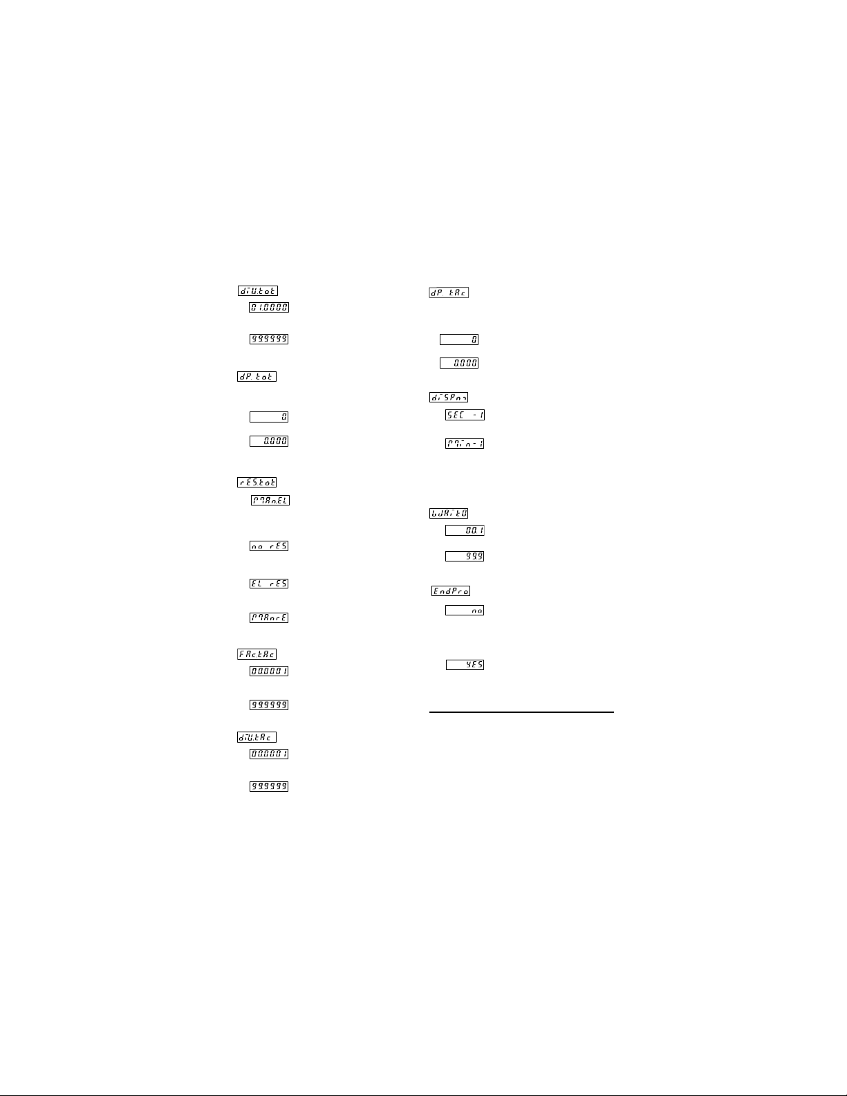
4.4 Dividing factor ( totaliser)
It can be set from 00.0001 up
to 99.9999.
The decimal point is set to 4
decimal places.
„0“ is not accepted!
4.5 Decimal point (totaliser)
4.6 RESET-Mode (totaliser)
4.7 Multiplying factor (frequency meter)
4.8 Dividing factor (frequency meter)
The decimal point defines the
way of displaying the count values. It does not affect counting.
0 no decimal place
0.0 one decimal place
0.00 two decimal places
0.000 three decimal places
manual reset via the red
RESET key and electrical reset
via the RESET input
no reset (red RESET key and
RESET input locked)
only electrical r eset via the
RESET input
only manual reset via the red
RESET key
It can be set from 00.0001 up
to 99.9999.
The decimal point is set to 4
decimal places.
„0“ is not accepted!
4.9 Decimal point (frequency meter)
4.10 Display mode (frequency meter)
4.11 Max. time to wait until „0“ is displayed
(frequency meter)
This parameter indicates, how long it takes,
when measuring is active, until „0“ is displayed.
4.12 End of programming
The decimal point defines the
resolution in the selected
measuring range 1/m in or
1/sec
0 no decimal place
0.0 one decimal place
0.00 two decimal places
0.000 three decimal places
Value conversion a nd
display in 1/s
Value conversion a nd
display in 1/min
Max. time to wait 00.1 s
(min. value)
Max. time to wait 99.9 s
The programming routine is
repeated once more. The values set until now can be
checked and modified.
The programming routine wil be
left and all values set will be
stored as new parameters.
Afterwards the device is ready
for operation.
It can be set from 00.0001 up
to 99.9999.
The decimal point is set to 4
decimal places.
„0“ is not accepted!
3
Find Quality Products Online at: [email protected]
www.GlobalTestSupply.com
Page 5
Page 6
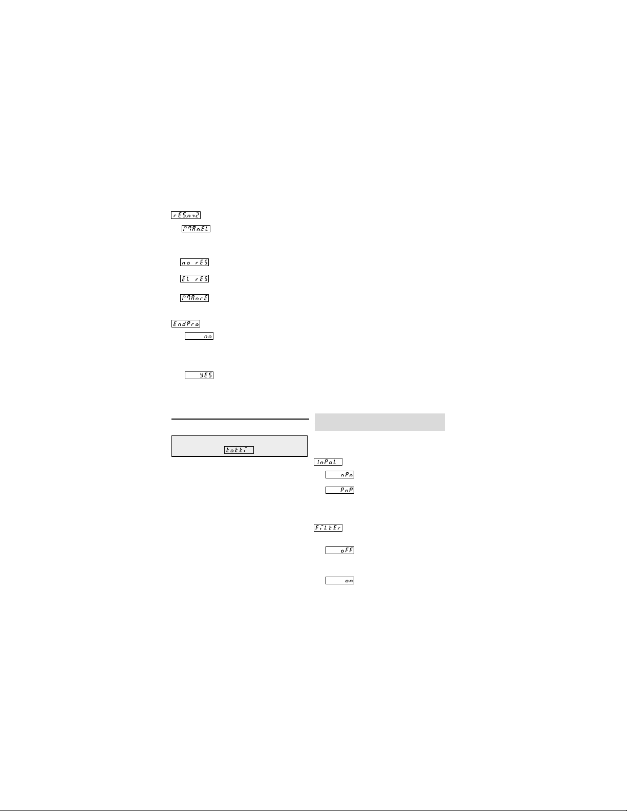
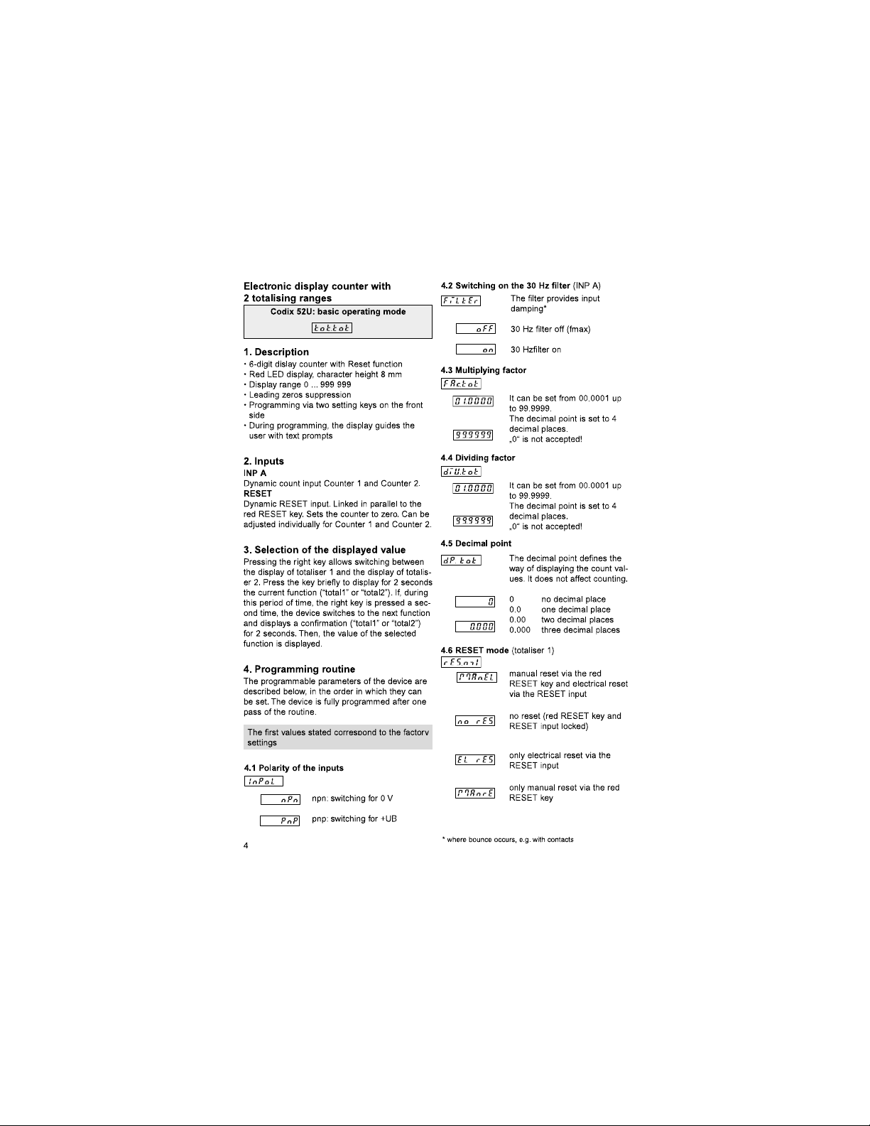
4.7 RESET Mode (totaliser 2)
manual reset via the red
RESET key and
electrical reset via the RESET
input
no reset (red RESET key and
RESET input locked)
only electrical res et via the
RESET input
only manual reset via the red
RESET key
4.8 End of programming
The programming routine is
repeated once more. The values set until now can be
checked and modified.
The programming routine wil be
left and all values set will be
stored as new parameters.
Afterwards the device is ready
for operation.
Electronic totaliser and time meter
Codix 52U: basic o perating mode
1. Description
• 6 digit totaliser and time meter with Reset function
• Red LED display, character hei ght 8 mm
• Display range 0 ... 999 999
• Leading zeros suppression
• Programming via two setting keys on the front
side
• During programming, the display guides the
user with text pr ompts
• Operation indicator: th e decimal point of the
lowest digit blinks while the count is active.
• Time meter operating modes:
– Counting while INP B is inactive “GAtE.Lo”
– Counting while INP B is active “GAtE.hi”
– Count Start/Stop with INP B edge B “Inb.Inb”
• Counting ranges: h; min; s; h.min.s
2. Inputs
INP A
Dynamic count input for the totaliser.
INP B
Start-/Stop or gate input for time meter
(independent of the input mode)
RESET
Dynamic RESET input. Linked in parallel to the
red RESET key. Sets the counter to zero. Can
be adjusted individually for the totaliser and the
time meter.
3. Selection of the displayed value
Pressing the r ight key allows switching between
the totaliser display and the time met er display
. Press the key briefly to display for 2 seconds
the current function (“total” or “time”). If, during
this period of time, the right key is pressed a
second time, the device switches to the next
function and displays a confirmation (“total” or
“time”) for 2 seconds. Then, the value of the
selected function is displayed.
4. Programming routine
The programmable parameters of the device
are described below, in the order in which they
can be set. The device is fully programmed
after one pass of the routine.
The first values stated correspond to the
factory settinfs
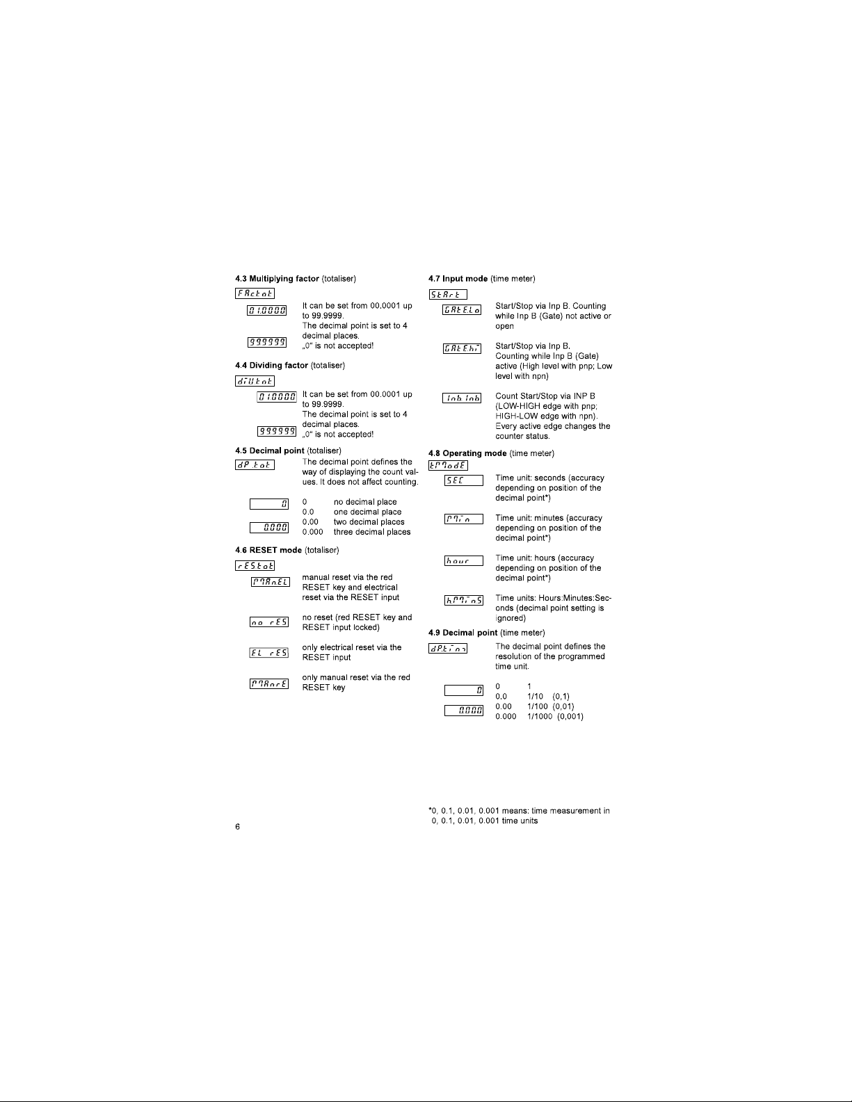
4.1 Polarity of the inputs
npn: switching for 0 V
pnp: switching for +U
4.2 Switching on the 30 Hz filter (INP A, INP B)
The filter provides input
damping*
30 Hz filter off (fmax)
Count and star t/stop inputs not
damped
30 Hz filter on
Count and star t/stop inputs
damped
* where bounce occurs, e.g. with contacts
B
5
Find Quality Products Online at: [email protected]
www.GlobalTestSupply.com
Page 7
Page 8
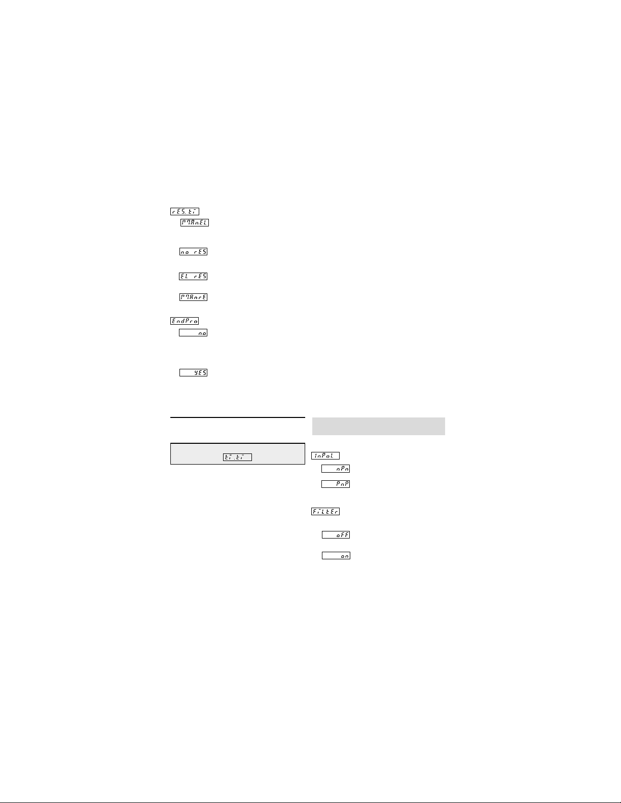
4.10 RESET mode (time meter)
manual reset via the red
RESET key and electri cal reset
via the RESET input
no reset (red RESET key and
RESET input locked)
only electrical reset via the
RESET input
only manual reset via the red
RESET key
4.11 End of programming
The programming routine is
repeated once more. The values set until now can be
checked and modified.
The programming routine wil be
left and all values set will be
stored as new parameters.
Afterwards the device is ready
for operation.
Electronic time meter with
2 time ranges
Codix 52U: basic o perating mode
2. Inputs
INP A
Start input (depending on the input mode chosen)
INP B
Time meter Star t/Stop or gate input (depending
on the input mode chosen)
RESET
Dynamic RESET input.Linked in parallel to the red
RESET key. Resets the counter to zero. Can be
adjusted individually for Counter 1 and Counter 2.
3. Selection of the displayed value
Pressing the right key allows switching between
the display of time meter 1 an d the display of
time meter 2. Press the key briefly to display for
2 seconds the current function (“time1” or
“time2”). If, during this period of time, the right
key is pressed a second time, th e device switch-
es to the next function and displays a confirma-
tion (“time1” or “time2”) for 2 seconds. T hen, the
value of the selected function is displayed.
4. Programming routine
The programmable parameters of the device are
described below, in the order in which they can
be set. The device is fully programmed after one
pass of the routine.
The first values state d correspond to th e
factory settings
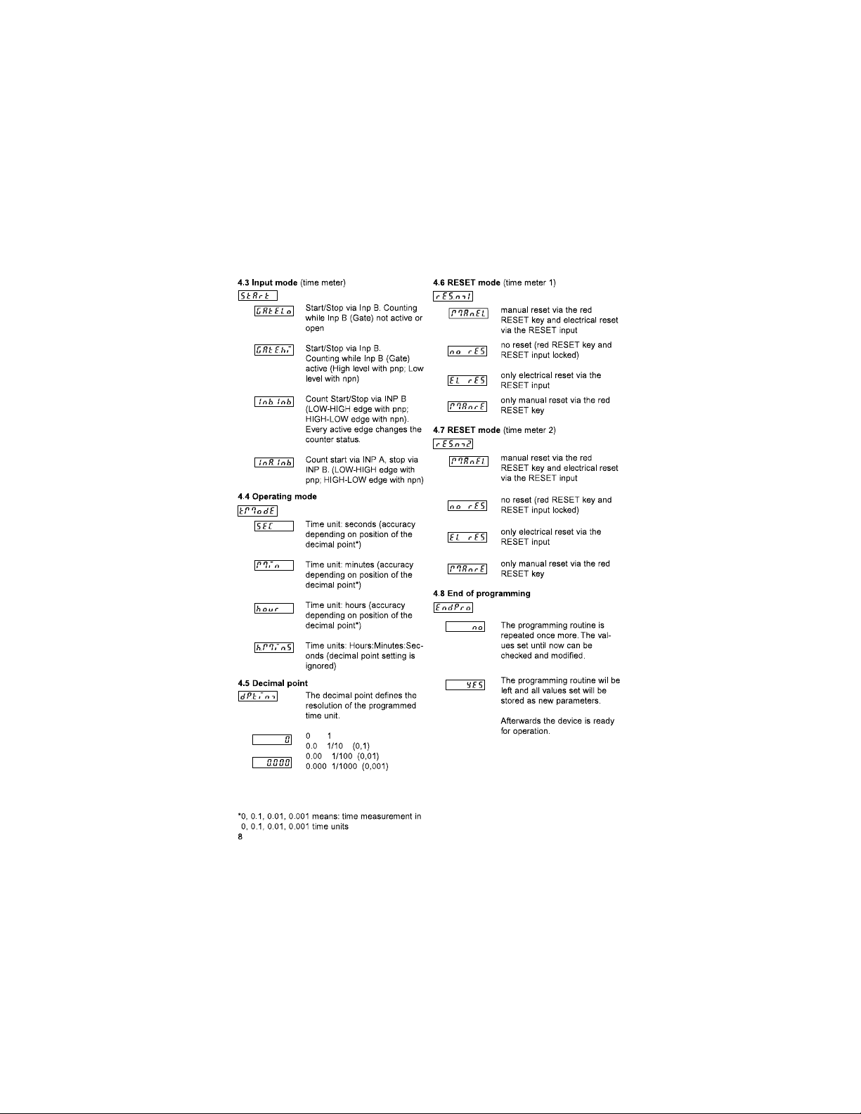
4.1 Polarity of the inputs
1. Description
• 6 digit time meter with Reset function
• Red LED display, character height 8 mm
• Display range 0 ... 999 999
• Leading zeros suppression
• Programming via two setting keys on the front
side
• During programming, the display guides th e
user with text promp ts
• Operation indicator: the decimal point of the
lowest digit blinks while the count is active
• Time meter operating modes:
– Counting while INP B is inactive “GAtE.Lo”
– Counting while INP B is active “GAtE.hi”
– Count Star t/Stop with INP B edge (Inb.Inb)
– Count Star t with INP A edge, count S top with
INP B edge (InA.InB)
npn: switching for 0 V
pnp: switching for +UB
4.2 Switching on the 30 Hz filter (INP A,INP B)
* where boun
The filter provides input
damping*
30 Hz filter off (fmax)
Start/Stop inputs not damped
30 Hz filter on
Start/Stop inputs damped for
use with mechanical switches
ce occurs, e.g. with contacts
7
Find Quality Products Online at: [email protected]
www.GlobalTestSupply.com
Page 9
Page 10
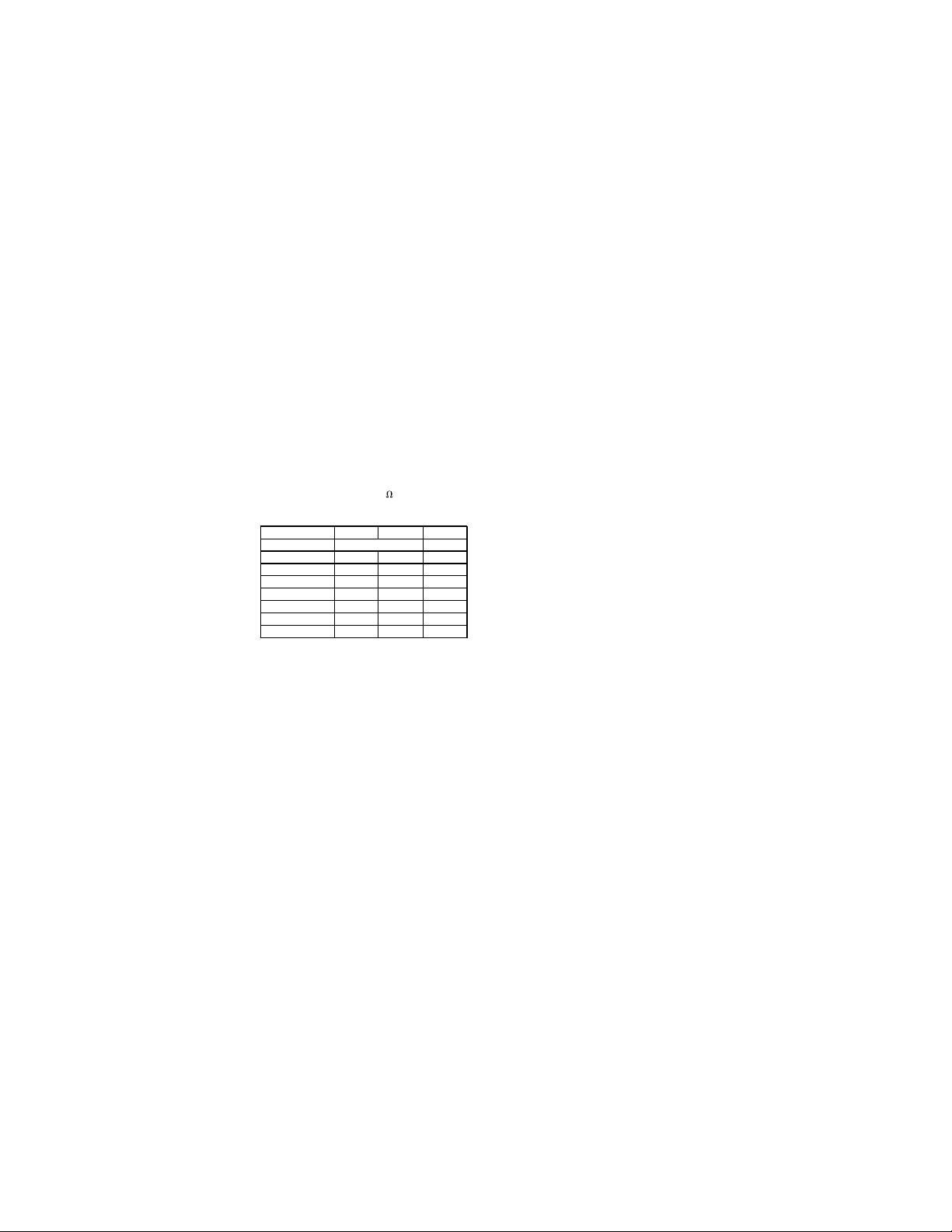
5. Technical data
Supply voltage
DC power supply: 10 ... 30 V DC/max. 55 mA
Display: 6 digits, red 7 segment
Data retention: EEPROM
Polarity of the inputs:
Input resistance: appr. 5 k
Count frequency:
DC power supply 24 V 12 V 10 ...30 V
Input level: Standard 5V
typ. low level 2,5 V 2,0 V 1,0 V
typ. high level 22,0 V 10 V 4,0 V
Fmax:* kHz kHz kHz
tot.tac 35 20 8
tot.tot 60 20 8
1)
tot.ti
2)
tot.ti
* at maximum frequency square wave pulses 1:1
1) Start Gate.Lo Inp B not activ
2) Start InpB.InpB and Inp B connected
with Inp A
Frequency measurement:
Accuracy : < 0.1 %
Measuring principle:
< 38 Hz: period measurement
> 38 Hz: gating time measurement
Time count ranges:
Seconds 0,001 s ... 999999 s
Minutes 0,001min ... 999999 min
Hours 0,001 h ... 999999 h
h.min.s 00 h 00 min 01 s
Accuracy <50 ppm
Minimum pulse length for the Reset input:
5 ms
with inverse-polarity
protection
LED display, height 8 mm
Programmable, npn or pnp
for all inputs
40 20 8
15 10 8
gating time = 26,3 ms
... 99 h 59 min 59 s
Input sensitivity:
Standard sensitivity:
4 ... 30 V DC level: Low: 0 ... 2 V DC
Pulse shape: any,
Ambient temperature:
-20 ... +65 °C at 10 ... 26 V DC
-20 ... +55 °C at >26 ... 30 V DC
Storage temperature:
Altitude: to 2000 m
EMC:
Noise emission EN 55 011 Class B
Noise immunity EN 61 000-6-2
Housing: For front panel mo unting:
Weight: appr. 50 g
Protection: IP 65 (front)
Cleaning: The front of the units is to
Low: 0 ... 0,2 x UB [V DC]
High: 0,6 x UB ... 30 [V DC]
High: 4 ...30 V DC
Schmitt-Trigger inputs
–25 ... +70 °C
48 x 24 mm acc. to DIN
43700, RAL7021, dark grey
be cleaned only with a soft
wet (water !) cloth.
9
Find Quality Products Online at: [email protected]
www.GlobalTestSupply.com
Page 11
 Loading...