

Page 1

Ultrastore Rapid GE
Operating instructions
Installation instructions Page 9
To be kept in the vehicle!
Page 3
Page 2

Ultrastore Rapid GE
Showering with the Ultrastore Rapid GE
The Truma Ultrastore Rapid GE has 10 litre capacity. It is more
than capable of heating enough water to give out three consecutive hot showers.
When using the boiler, you should observe the following
points to achieve this:
Switch the Ultrastore on 16 minutes before required use.
–
Switch on dual power mode (gas and electricity),
–
Gas operation – 70 °C / electric operation – 1300 W
Set the mixing tap in the shower to approx. 38 °C and
–
maintain a medium flow rate (approx 2.5 l / minute) when
in the shower
Switch off the water when applying shampoo / shower gel etc.
–
Do not switch the Ultrastore off when showering
–
As long as the Ultrastore remains in operation, other people
can shower as the water is continually reheated.
Example: Sufficient warm water capacity for three consecutive hot showers
Water temperature 38 °C
Water flow rate 2.5 l / minute
Water consumption per person 12.5 l
2 minutes
Heat up
45 minutes
1 minute
012345678910111213
80
70
60
50
(°C)
40
Temperature
30
20
10
0
1
2
3
4
3 minutes
1 minute
Pause
2 minutes
3 minutes
1 minute
Time t (minutes)
Switch off the water
when applying shampoo / shower gel.
2 minutes
Pause
1 minute
14 15 16 17 18 19 20
1 minute
3 minutes
8
7,5
7
6,5
6
5,5
5
4,5
4
3,5
3
2,5
Water flow (filter / minunte)
2
1,5
1
0,5
0
1
2
Warm water (Ultrastore) temperature
Mixed temperature tap
3
4
Water flow
Cold water temperature
2
Page 3

Table of contents
Symbols used
Symbols used ........................................................................ 3
Safety instructions ............................................................ 4
Important operating notes ............................................... 4
Operating instructions
Filling the Truma Ultrastore with water ................................. 5
Draining the water heater ..................................................... 5
Switching on Gas operation ............................................. 5
Switching off ........................................................................ 5
Red LED “Failure” ................................................................ 5
Switching on Electric operation ...................................... 5
Maintenance ....................................................................... 6
Fuses ..................................................................................... 6
Disposal ................................................................................. 6
Technical data ..................................................................... 6
Trouble-shooting list .......................................................... 7
Declaration of conformity ................................................ 8
Manufacturer’s terms of warranty .................................. 8
Installation instructions
Intended use .......................................................................... 9
Regulations ............................................................................ 9
Water heater kit ................................................................. 9
Choice of location .............................................................. 9
Installation of the water heater ....................................... 9
Water connection ........................................................... 10
John Guest System rigid pipe routing ............................... 10
Flexible water hose routing ................................................. 11
Installation of the safety (pressure relief) drain valve .......... 11
Water pipe routing .............................................................. 11
Gas connection ................................................................. 11
Installation of the control panels .................................. 12
Electrical connection 12 V ............................................. 12
Electrical connection 230 V ........................................... 13
Connection 230 V control panel ......................................... 13
Function check ................................................................. 13
Warning information ....................................................... 13
Accessories ....................................................................... 14
Symbol indicates a possible hazard.
Comment including information and tips.
3
Page 4

Safety instructions
The use of upright gas cylinders from which gas is taken in
the gas phase is mandatory for the operation of gas regula-
tors, gas equipment and gas systems. Gas cylinders from
which gas is taken in the liquid phase (e.g. for fork lifts) must
not be used, since they would result in damage to the gas
system.
In event of leaks in the gas system or if there is a smell of gas:
Items sensitive to heat (e.g. spray cans) must not be stored
in the installation area, since excess temperatures may under
circumstances be incurred there.
Only pressure control equipment that complies with EN 12864
(in vehicles) with a fixed delivery pressure of 30 mbar must be
used for the gas system. The flow rate of the pressure control
device must correspond to at least the maximum consumption of all devices installed by the system manufacturer.
extinguish all naked flames
–
do not smoke
–
switch off all appliances
–
shut off the gas cylinder
–
open the windows and doors
–
do not actuate any electrical switches
–
have the entire system checked by an expert!
–
Repairs may only be carried out by an expert.
During use, please observe the regulations of EN 60335-1:2010,
according to which this device has not been designed for use
by people (including children) who have restricted physical,
sensory or mental abilities or a lack of experience and / or
knowledge, unless they are supervised by a person responsible for their safety or have received instructions from that
person as to how the device is to be used.
Children should be supervised to ensure they do not play with
the device.
To avoid risk caused by unintentional resetting of the
overtemperature sensor, the device may not be supplied
via an external switching device, such as a timer, or be connected with a circuit that is regularly switched on and off by
any kind of equipment.
Guarantee claims, warranty claims and acceptance of liability
will be ruled out in the event of the following:
modifications to the unit (including accessories),
–
modifications to the exhaust duct and the cowl,
–
failure to use original Truma parts as replacement parts and
–
accessories,
failure to follow the installation and operating instructions.
–
It also becomes illegal to use the appliance, and in some
countries this even makes it illegal to use the vehicle.
The operating pressure for the gas supply (30 mbar) must correspond to the operating pressure of the appliance (see data
plate).
Liquid gas systems must accord with the technical and
administrative regulations of the particular country in which
they are being used (e.g. EN 1949 for vehicles). National
regulations must be respected.
Important operating notes
If the cowl has been placed near or directly beneath an opening window, the device must be equipped with an automatic
shut-off device in order to prevent operation with the window
open.
Always mount the cowl cap if the water heater is not being
used. Non-observance of this point can lead to the function of
the appliance being impaired through water, dirt or insects.
Before setting off on any journey, fit cowl cap with the
boiler switched off. Please ensure that it is secure and
has locked into place (risk of accident). Defective cowl caps
must not be used.
There shall be no claim under guarantee if this point is not
observed. Always remove the cowl cap prior to operating the
water heater!
If just the cold water system is being used, without water
heater, the heater tank is also filled up with water. In order
to avoid damage through frost, the water contents must be
drained by actuating the safety/drain valve, also when the
heater has not been used. As an alternative, two shut-off
valves, resistant to hot water, can be fitted in front of the cold
and hot water connection.
Drain the water heater if there is a risk of frost! There
shall be no claim under guarantee if this point is not
observed.
If connecting to a central water supply (rural or city connection) or when using more powerful pumps, a pressure reducer
must be used which prevents pressures of greater than 2.8 bar
occurring in the Ultrastore.
The testing of the gas system must be repeated every two
years by a qualified specialist and, if appropriate, confirmed
on the inspection certificate.
The vehicle owner is always responsible for arranging
the inspection.
Liquid gas equipment must not be used when refuelling,
in multi-storey car parks, in garages or on ferries.
During the initial operation of a brand new appliance (or after
it has not been used for some time), a slight amount of fumes
and a slight smell may be noticed for a short while. Remedial
action here is to immediately run the heater and to ensure adequate room ventilation.
If the burner makes an unusual noise or if the flame lifts off,
it is likely that the gas pressure regulator is faulty and it is
essential to have it checked.
4
Page 5

Operating instructions
Always observe the operating instructions prior to
starting! The vehicle owner is responsible for the correct
operation of the appliance.
The installer or vehicle owner must apply the yellow sticker
with the warning information, which is enclosed with the
appliance, to a place in the vehicle where it is clearly visible to
all users (e.g. on the wardrobe door)! Ask Truma to send you
stickers, if necessary.
Before using the first time, it is essential to flush the
entire water supply through with clean warm water.
Always mount the cowl cap when the water heater is not being operated! Drain the water heater if there is a risk of frost!
There shall be no claims under guarantee for damage
caused by frost!
Materials in the device which come into contact with water
are suitable for use with drinking water (see manufacturer
declaration: www.truma.com – Manufacturer Declaration).
Filling the Truma Ultrastore with water
Check that the safety/drain valve in the cold water intake is
closed: Lever should be in horizontal position, position (e).
f
e
e
Switching on Gas operation
Ultrastore
50°
b
c
a
a = Red LED “Failure”
b = Water heater “On” 50 °C or 70 °C
c = Water heater “Off”
Never operate the water heater without water in it!
If the cowl is positioned vertically below an opening part of
a window, the water heater must be fitted with an automatic
shut-off device to prevent operation when the window is open.
Remove cowl cover.
Open gas cylinder and open quick-acting valve in the gas supply line.
Switch on water heater at the switch on the control panel (b).
When using the vehicle switches: refer to operating instructions of the vehicle manufacturer or see switch labels.
If there is air in the gas supply line, it may take up to a minute
before the gas is available for combustion. If the appliance
switches to “Failure” during this period, switch off the appliance – wait 5 minutes – and switch on again!
70°
b
e = Lever position “Closed”
f = Lever position “Drain”
Open hot tap in bathroom or kitchen, with pre-selecting mixing taps or single-lever fittings set to “hot”.
Switch on power for water pump (main switch or pump switch).
Leave the tap open to let air escape while the water heater is
filling. The heater is filled when water flows out of the tap.
Residues of frozen water can prevent filling if there is a frost.
The water heater can be defrosted by switching on the heater
for a short period (max. 2 minutes). Frozen pipes can be
defrosted by heating the room.
Draining the water heater
If the mobile home is not used during periods of frost, it
is essential that the Truma Ultrastore be emptied.
Disconnect power for water pump (main switch or pump
switch).
Switching off
Switch off the water heater (c). Mount cowl cap. Drain the
water heater if there is a risk of frost. Close quick-acting valve
in the gas supply line if the appliance is not to be used for a
longer period of time and close the gas cylinder.
Red LED “Failure”
The red LED (a) lights up if there is a failure. For possible causes please refer to page 7. To unlock, switch off the appliance,
wait 5 minutes, and switch on again.
Switching on Electric operation
(230 V ~, 850 W, 3.7 A / 1300 W, 5.7 A)
Ultrastore
g – 850 W
h
g – 1300 W
230 V ~
g = Water heater “On” 850 W or 1300 W
h = Water heater “Off”
Open hot water taps in bathroom and kitchen.
Open safety/drain valve: Lever in vertical position, position (f).
The water heater is now drained directly to the outside via the
safety/drain valve. Check that the water contents have been
completely drained (10 litres).
Never operate the water heater without water in it!
Switch on at the control panel (g).
When using the vehicle switches: refer to operating instructions of the vehicle manufacturer or see switch labels.
The water temperature cannot be selected, automatic
temperature limitation at approx. 70 °C! For a faster
heating up period the appliance can be simultaneously operated with gas and electrical power.
5
Page 6
The electrical heating element is equipped with an over-
temperature sensor. In the event of a fault, switch off at
the operating element. Check water content, refill if required
(close drain valve). Wait 10 minutes, then switch on again.
Technical data
Determined in accordance with EN 15033 or
Truma test conditions.
Maintenance
We recommend to use twice a year the Truma system care
set for cleaning, disinfecting and looking after the boiler. Other
products – in particular products containing chlorine – are
unsuitable.
To avoid infestation by micro-organisms, the water content
must be heated to 70 °C at regular intervals.
Clean the device and the ventilation slits with a dry and flufffree cloth.
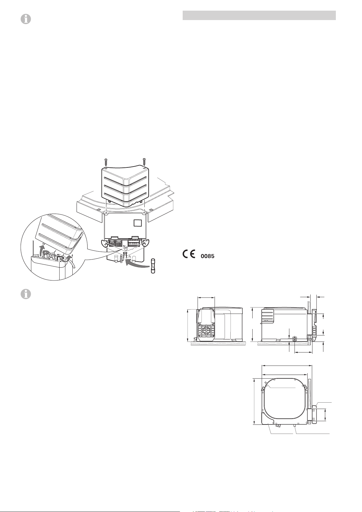
Fuses
The water heater 12 V fuse is on the electronic control unit on
the water heater.
Manufacturer
Truma Gerätetechnik GmbH & Co. KG
P.O. Box 1252
85637 Putzbrunn (Munich)
Germany
Water contents
10 litres
Pump pressure
max. 2.8 bar
System pressure
max. 4.5 bar
Type of gas
Liquid gas (propane / butane)
Operating pressure
30 mbar
Rated thermal output
1500 W
Gas consumption
120 g/h
Heating up time from approx. 15 °C to approx. 70 °C
Rapid GE – 10 litres
Gas operation: approx. 31 min.
Electrical operation: approx. 29 min.
Gas and electrical operation: approx. 16 min.
Power consumption 12 V
Ignition: 0.17 A
Heating up: 0.08 A
Standby: 0.04 A
Power consumption 230 V
Heating up: (3.7 A) 850 W / (5.7 A) 1300 W
Stand-by Consumption Gas
approx. 70 W
Weight (empty)
approx. 7.2 kg
1.6 A
Only replace the miniature Fuse on the p.c.b. with a fuse
of the same type: 1.6 A, EN 60127-2-3 (slow action).
If there is a defect in the electronics, return the control p.c.b.
well padded. If you fail to pack it correctly the guarantee shall
no longer be valid.
Only use original Truma Ultrastore control p.c.b.'s as spare parts!
Disposal
The device must be disposed of in line with the administrative
regulations of the respective country in which it is used.
National regulations and laws (in Germany, for example, the
End-of-life Vehicle Regulation) must be observed.
The right to effect technical modifications is reserved!
Dimensions
30
25
132
383
347
gas connection
245
129
261
349
water
connections
electronic
168
47
cowl
92
cut out
cut out
All dimensions in mm.
6
Page 7

Trouble-shooting list
Fault Cause Rectification
Gas operation
When switching on, the
heater does not operate.
When switching on, the heater
does not operate and the red
lamp lights up after approx.
30 secs.
Heater operates for a prolonged
time and then the red lamp
lights up.
Electrical operation
When switching on, the
heater does not operate.
No 12 V supply voltage.
–
Window open.
–
Cowl cover fitted.
–
No gas supply.
–
Incorrect gas pressure.
–
Air in the gas supply.
–
Over temperature sensor
–
has responded.
No 230 V supply voltage.
–
Over temperature sensor
–
has responded.
Check the power supply (operation voltage min. 10.5 V).
–
Check the water heater fuse
–
(refer to mainanance “Fuses”).
Close any windows above the cowl.
–
Remove cowl cover and / or clear any obstruction.
–
Check gas valves and gas bottle.
–
Check gas valves and gas bottle.
–
To unlock (and purge air), switch off the appliance, wait
–
5 minutes, and switch on again.
Check water content, refill if required (close drain valve).
–
To unlock, switch off the appliance, wait 5 minutes, and
–
switch on again.
Connect the caravan to the site supply and / or check
–
residual current circuit breaker.
Check water content, refill if required (close drain valve).
–
The electrical heating element is fitted with an excess
–
temperature cut-out. In event of a fault, switch off at the
control panel, wait 10 minutes, then switch on again.
Too slow warm-up in
–
position 850 W.
Please contact the Truma Service.
–
Water supply
Water drips from the
safety/drain valve.
When opening the cold water
tap, hot water tap comes out.
If this does not solve the problem, please contact the Truma Service.
Water pressure to high.
–
Hot water flows back
–
through the cold water
supply.
Check water pressure (max. 2.8 bar), use a pressure
–
reducer when connected to central water supply.
Fit a no-return valve in the cold water supply
–
(refer to installation instructions “Water connection”).
7
Page 8
Declaration of conformity
Manufacturer’s terms of warranty
1. Information about the manufacturer
Name: Truma Gerätetechnik GmbH & Co. KG
Address: Wernher-von-Braun-Str. 12, D-85640 Putzbrunn
2. Device identification
Type / model
LPG-water heater / Boiler Ultrastore Rapid GE (UGE 10)
3. Meets the requirements of the following Directives
3.1 Gas Appliances Directive 90/396/EEC
3.2 Low Voltage Directive 2006/95/EC
3.3 Radio Interference in Vehicles 72/245/EEC
(with the supplements), UN ECE R10
3.4 Electromagnetic Compatibility 2004/108/EC
3.5 End-Of-Life Vehicle Directive 2000/53/EC
3.6 Drinking Water Directive 98/83/EC
and bears the type approval numbers
e1 03 2604, E1 10R–03 2604
and the CE symbol with the CE product ident. no.
CE-0085CL0489.
4. Basis of the conformity assessment
2004/104/EC, 2005/83/EC, EN 89, EN 15033, EN 298 (partly),
DIN EN 60335-1:2010,
IEC 60335-1:2001 mod. +A1:2004 + A2:2006,
DIN EN 60335-2-21:2009,
IEC 60335-2-21:2002 mod. + A1:2004 + A2:2008,
DIN 2001-2, DVGW W270, KTW.
EN 55014-1, CISPR 14-1,
EN 61000-3-2, IEC 61000-3-2,
EN 61000-3-3, IEC 61000-3-3,
ISO 7637 Part 2, ISO 7637 Part 3,
EN 55014-2, CISPR 14-2, EN 13611 Type B,
EN 61000-4-2:2009, IEC 61000-4-2,
EN 61000-4-3, IEC 61000-4-3, EN 61000-4-4, IEC 61000-4-4,
EN 61000-4-5, IEC 61000-4-5, EN 61000-4-6, IEC 61000-4-6,
EN 61000-4-8, IEC 61000-4-8
1. Case of warranty
The manufacturer grants a warranty for malfunctions in the
appliance which are based on material or production faults.
In addition to this, the statutory warranty claims against the
seller remain valid.
A claim under warranty shall not pertain:
for parts subject to wear and in cases of natural wear
–
and tear,
as a result of using components in the units that are not
–
original Truma parts and using unsuitable gas pressure
regulators,
as a consequence of failure to respect Truma instructions
–
for installation and use,
as a consequence of improper handling,
–
as a consequence of improper transport packing,
–
use of water not compliant to Drinking Water Directive
–
98/83/EEC.
2. Scope of warranty
The warranty is valid for malfunctions as stated under
item 1, which occur within 24 months after conclusion of
the purchase agreement between the seller and the final
consumer. The manufacturers will make good such defects
by subsequent fulfilment, i.e. at their discretion either by
repair or replacement. In the event of manufacturers providing service under warranty, the term of the warranty shall not
re commence a new with regard to the repaired or replaced
parts; rather, the old warranty period shall continue to run.
More extensive claims, in particular claims for compensatory
damages by purchasers or third parties, shall be excluded.
This does not affect the rules of the product liability law.
The manufacturer shall bear the cost of employing the Truma
customer service for the removal of a malfunction under warranty – in particular transportation costs, travelling expenses,
job and material costs, as long as the service is carried out in
Germany. Customer service carried out abroad is not covered
by the warranty.
5. Auditing body
DVGW, Federal Motor Transport Authority
6. Information and the function of the signatory
Signature: Dr. Andreas Schmoll
Managing Director / Engineering Putzbrunn, 10.01.2011
Additional costs based on complicated removal and installation conditions of the appliance (e.g. removal of furniture or
parts of the vehicle body) do not come under warranty.
3. Raising the case of warranty
The manufacturer's address is:
Truma Gerätetechnik GmbH & Co. KG,
Wernher-von-Braun Strasse 12,
85640 Putzbrunn (Germany).
In Germany, always notify the Truma Service Centre if problems are encountered; in other countries the relevant service
partners should be contacted (see Truma Service Booklet or
www.truma.com). Any complaints are to be described in detail. Please also specify the device serial number and date of
purchase.
In order for the manufacturers to be able to determine whether
an incident subject to guarantee has occurred, the end user
must, at his own risk, bring the device to the manufacturers or
send it to them. If there is damage to heaters (heat exchangers),
the gas pressure regulator must also be sent back to the factory.
In instances of the device being sent to the works, dispatch is
to be effected by freight transport. In cases under guarantee,
the works shall bear the transport costs or the costs of delivery and return. If the damage is deemed not to be a warranty
case, the manufacturer shall notify the customer and shall specify repair costs which shall not be borne by the manufacturer; in
this case, the customer shall also bear the shipping costs.
8
Page 9
A
Installation instructions
Installation and repair are only to be carried out by an
expert. Always read and follow the operating instructions
carefully prior to starting any work!
Non-compliance with installation instructions or
incorrect installation can result in endangerment
of persons and property.
Choice of location
Always install the appliance in such a way that it is easily
accessible for service work at all times and can be easily
removed and installed.
Locate the heater in such a way that the cowl can be mounted
on the outside on a surface which is as straight and smooth
as possible. This outside surface must be exposed to wind
from all directions and, if possible, there should be no trim
strips or covers in this area, mount heater on an appropriate
base, if necessary.
Intended use
This appliance has been designed for the installation in caravans, motor homes and other vehicles. It is not approved
for installation in boats. Other forms of use are also possible
following consultation with Truma.
Information regarding boats: For installation in boats Truma
supplies the DVGW-tested boat water heater.
Regulations
Any modifications to the unit (including the exhaust duct and
the cowl) or the use of spare parts and accessories that are
important to the operation of the system (e.g. the time switch)
that are not original Truma parts and failure to follow the installation and operating instructions will cancel the warranty
and indemnify Truma from any liability claims. It also becomes
illegal to use the appliance, and in some countries this even
makes it illegal to use the vehicle.
In-vehicle installations must comply with the technical and
administrative regulations of the respective country of use
(e.g. EN 1949 for vehicles). The national regulations and rules
must be complied with.
Water heater kit
The water heater kit contains
1 Assembled water heater
1 Cowl assembly with screws
1 Hot water connector
1 Cold water connector
1 Safety (pressure relief) drain valve
1 Wall switch (gas operation) with 3 m cable
1 Wall switch (230 V operation)
1 Installation template
1 Set literature
1 Label with warning information
In order to guarantee complete emptying of the water content, ongoing sealing tightness of the water connections and
safety function all enclosed parts must be used!
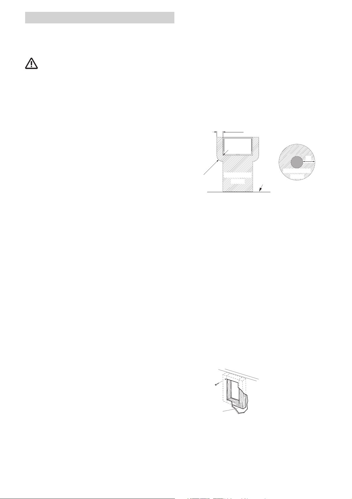
The cowl may not be positioned within 500 mm (A) of a refuelling point or fuel tank breather outlet or within 300 mm (A)
of a ventilator for the living space. If the cowl is positioned
vertically below an opening part of a window, the water heater
must be fitted with an automatic shut-off device (please refer
to page 14) to prevent operation when the window is open.
300 mm
Window
A
300 mm
The heater must not be installed close to or directly behind a
room / space heater.
To achieve reasonable air flow for electronics cooling,
there should be a minimum distance of 20 mm between the
electronics cover (34) and the walls of the furniture piece
the Ultrastore is located in.
Prohibited
Zone
Floor
Prohibited
Zone
Installation of the water heater
Position template for cowl opening on the inside of the wall.
A = bottom edge of heater
B = lateral edge of heater
Drill 4 holes (C) with 10 mm dia. through the wall. Drill hole (E)
with 15 mm dia. for condensation pipe (also possible from the
outside = F).
Position template on the outside of the wall. The markings (C)
must be above the through-holes. Saw cut-out section for
cowl (D) 92 x 168 mm.
If the distance between outside wall and heater is more than
35 mm you must use the cowl extension VBO 2 (please refer
to page 14) with an additional length of 50 mm. Saw out
100 x 176 mm along the dashed line.
If there are any cavities in
the area of the cowl, pack
these with pieces of wood
so as to be able to tighten
rea cut-away
for clarification
Cut out trim strips or such on the vehicle or place supports
beneath them so as to make the cowl lie flat.
Place a support beneath the heater if the walls are sloping.
An angle of inclination of 10 degrees is not to be exceeded.
the screws. The finished
hole should be 168 mm high
and 92 mm wide.
9
Page 10
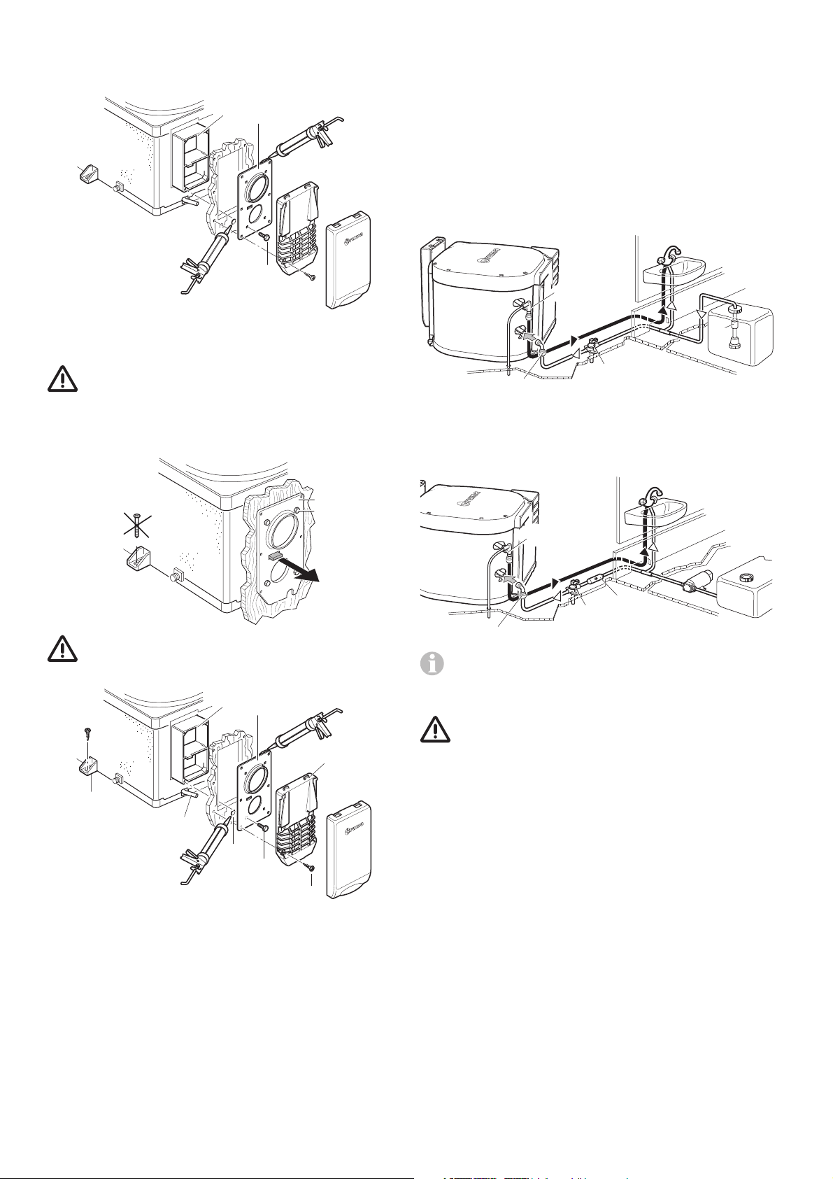
Insert heater with cowl body (1) through the wall cut-out (2),
allow approx. 5 mm to project out of the wall. Mount sealing
frame (3) (the anti-twisting device ensures correct fitting!).
Pre-drill holes for the 6 fastening bolts (4).
1
3
Water connection
All pressure and submergible waterpumps up to 2.8 bar
and all mixed combination sets with or without an electrical
switch, can be used for operating the water heater.
If connecting to a central water supply (rural or city connection) or when using more powerful pumps, a pressure
reducer must be used which prevents pressures of greater
than 2.8 bar occurring in the system.
2
4
Remove sealing frame (3) and coat with non hardening mastic
on the side facing the vehicle – do not use silicone!
The sealing frame must be well sealed with respect to
the front sides and the cross bars of the cowl body (1)
as well as towards the outside wall!
Fasten sealing frame (3) to the cowl body using 4 self-cutting
screws (4).
3
4
When using submergible pumps, a non-return valve (10 – not included in the scope of supply) must be fitted between the pump
and the first branch point (arrow points in direction of flow).
12
10
14
13
When using pressure pumps with high switching hysteresis,
hot water may flow back through the cold water tap. To prevent the backflow, we recommend that a non-return valve
(11 – not included in the scope of supply) be fitted between
the outlet to the cold water tap and the drain valve.
12
Screw the sealing frame (3) in contact together
with the cowl body (1) so the anti-twist device
projects out!
1
3
8
9
7
6
4
5
Seal the gap between the hole (6) and the condensation
tube (7) with non hardening mastic – do not use silicone!
Mount the grille (8). Press the entire cowl assembly onto the
vehicle wall and fasten with 6 screws (5).
11
14
13
When using the Truma Ultrastore together witch the
Truma Ultraflow pressure switch, the use of a non-returnvalve is essential (please refer to the pressure switch
instruction).
In order to guarantee complete emptying of the water
content and ongoing sealing tightness of the water
connections, the enclosed water connectors (12 + 13) and
the safety (pressure relief) drain valve (14) must be used!
John Guest System rigid pipe routing
The water connectors (12 + 13) and safety/drain valve (14)
supplied with the Truma Ultrastore have a 12 mm diameter
fitting and are only approved to use with Original John Guest
piping.
For connecting to rigid pipes with other diameters appropiate
adapters (not included in scope of delivery) must be used.
Screw the water heater securely to the floor of the vehicle
with at least two shackle plates (9) with the screws provided,
B 5.5 x 25, on suitable base (plywood panel, laminated wood
strips or metal base).
10
Page 11
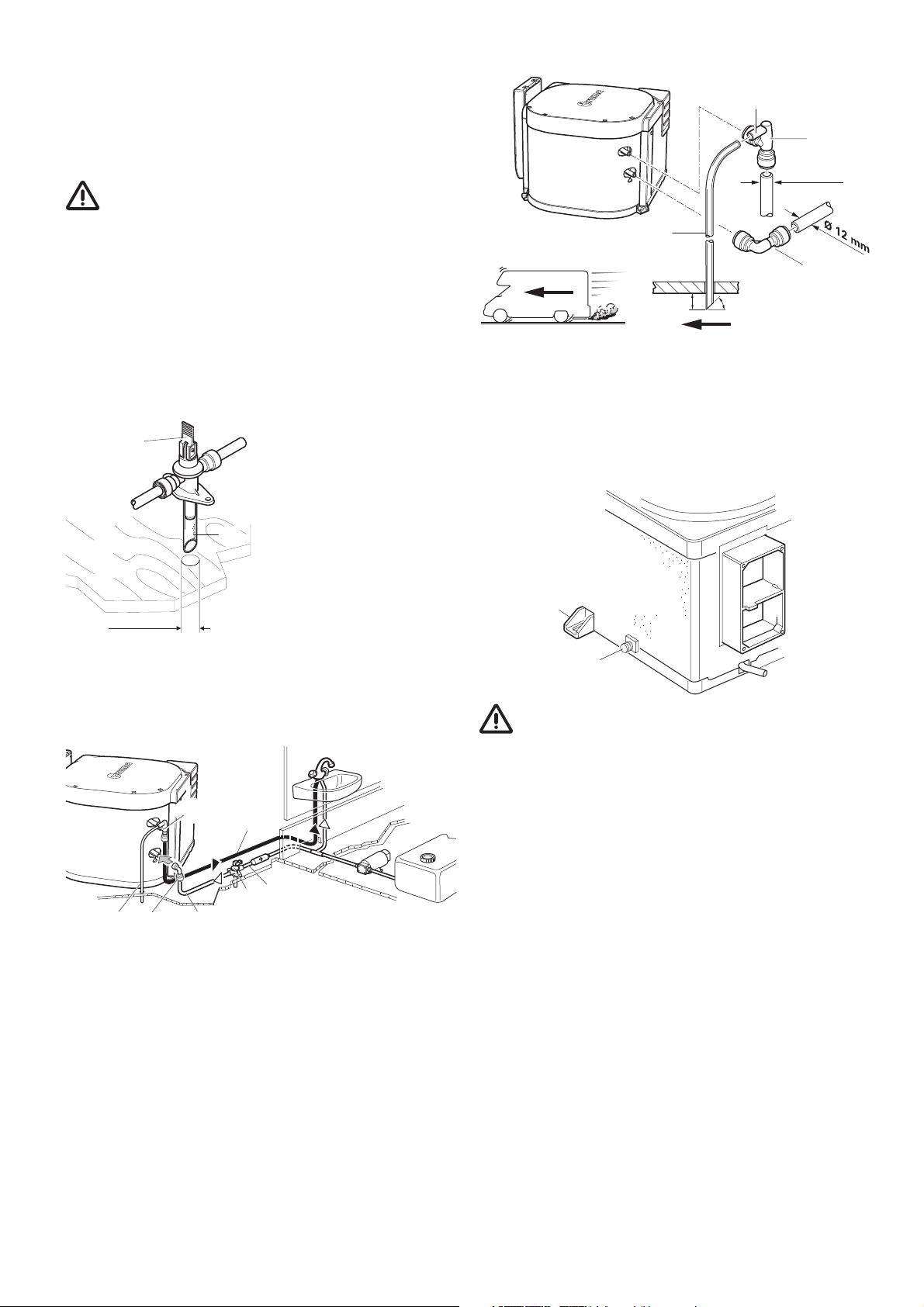
Flexible water hose routing
As special accessories Truma supplies the water connectors
(12 + 13) and safety/drain (14) valve with a 10 mm diameter
hose nipple (please refer to page 14).
Cut off the ventilation hose approx. 20 mm below the floor of
the vehicle at an angle of 45° to the direction of travel.
21
Pressure-resistant (up to 4.5 bar) and hot water-resistant water
hoses in food quality with an internal diameter of 10 mm must
be used.
Route water hoses so that they are as short and free
of kinks as possible. All hose connections must be
secured using hose clamps (also for cold water)! Pressures
of up to 4.5 bar can occur in the safety/drain valve (also with
submergible pumps) because of the heat of the water and the
resulting expansion.
All hot water hoses should be routed in a descending
manner to the safety/drain valve! Otherwise no guarantee of protection from frost!
Installation of the safety (pressure relief)
drain valve
14
Install the safety/drain valve
(14) at a place which is
easily accessible, near the
water heater. Drill hole with
15
Ø 18 mm
18 mm diameter and pass
through discharge socket
with hose (15). Fasten safety/
drain valve with 2 screws.
The draining is to be directly
to the outside at a position
protected against splash
water (apply splash guard, if
necessary).
12
Ø 12 mm
20
13
20 mm
Produce connection (22) for cold water supply between
safety/drain valve (14) and elbow (13 – lower pipe) on water
heater.
Route the hot water pipe (23) from the elbow with integrated
breather valve (12 – upper pipe) to the hot water consumers.
45º
Gas connection
Water pipe routing
Connect cold water supply (16) to safety/drain valve (14).
Direction of flow is unimportant.
12
13
20
Slide elbow fitting (13) onto cold water connecting pipe (lower
pipe) and elbow fitting with integrated ventilating valve (12)
onto hot water connecting pipe (upper pipe) of water heater
as far as it will go. Pull in opposite direction in order to make
sure the elbow fittings are securely attached.
Push the venting hose, external diameter 11 mm (20), onto
the hose grommet of the venting valve (21), and lay it to the
outside without any kinks. Ensure that the bend radius is not
smaller than 40 mm.
22
23
14
16
38
The operating pressure for the gas supply is 30 mbar
and must correspond to the operating pressure of the
appliance (see name plate).
The 8 mm gas supply line is connected to the connection nozzle (38) with cutting ring connection. The cutting rings are to
be selected according to the gas pipe used (for copper pipe:
support sleeves and brass cutting ring as supplied). Carefully
hold in place with a second wrench when tightening!
Before connecting to the water heater make sure that the gas
lines are free from dirt, chips and such!
Route the pipes in such a way that the appliance can be
removed again for servicing.
In areas frequented by people, keep the number of parting
connections in the gas supply line to an technically feasible
minimum.
The entire system must accord with the technical and
administrative provisions of the individual country of use
(e.g. EN 1949 for vehicles). National specifications and
regulations must be respected.
11
Page 12
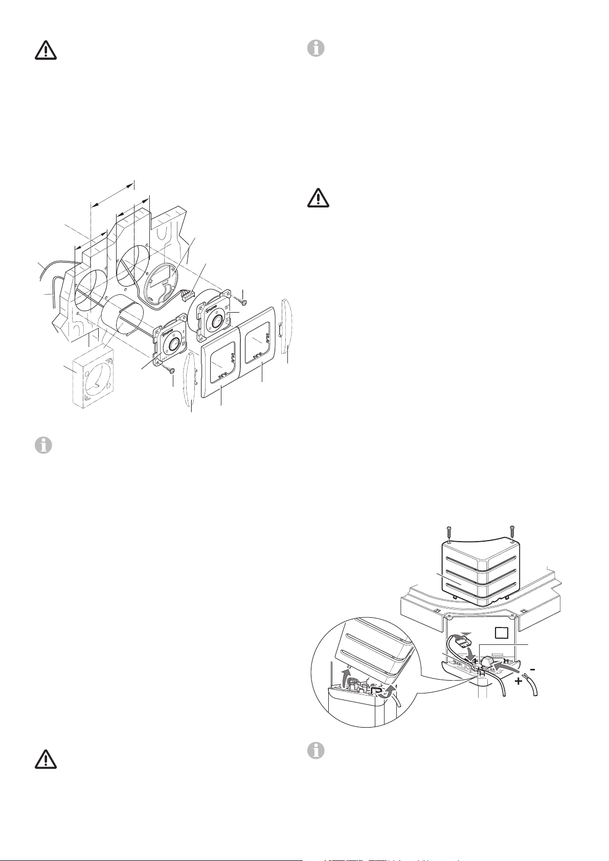
Installation of the control panels
Push on the front cover frame (32).
When using control panels which are specific to the
vehicle or the manufacturer, the electrical connection
must be established in accordance with the Truma interface
descriptions (refer to Electrical connection 230 V). Any modification made to the Truma components pertaining to this
will lead to the invalidation of the guarantee, as well as to the
exclusion of any claims for liability. The installer (manufacturer)
is responsible for providing instructions for use for the user as
well as for identification printing on the control panels.
When selecting the location, please bear the length of the
connection cable
can be supplied (please refer to page 14).
Ø 50 mm
28
30
of 3 m. If required, a cable extension of 5 m
66 mm
Ø 55 mm
29
28
31
27a
26
To round off the appearance of the cover frame, Truma
can provide side pieces (33) as special accessories in
8 different colours (please ask your dealer).
Electrical connection 12 V
Always disconnect the appliance from the power supply prior
to working on electrical components. It is not sufficient to just
switch off at the control panel!
The appliance must be disconnected from the vehicle main
power supply when carrying out any electric welding work on
the vehicle body.
If the connections are transposed there is a risk of
cable burning. This also rules out any guarantee or
liability claims.
Unscrew cover (34) from the electronic control unit. Slide
cable connector of control panel (28a) onto the p.c.b..
Put the cable (28) into the cable guide (28b) to fasten it securely.
The electrical connection 12 V is made at terminal (35).
orange = positive 12 V
blue = negative
To connect press with a small screwdriver from above and
push in cable from the front.
25
27
31
32
33
If it is not possible to install the control panels flush
with the surface, Truma can provide a surface-mounting frame (25) on request, as a special accessory (part no.
40000-52600).
The control panel for gas operation (26) and (if provided by
Truma) the control panel for electrical operation (27) should be
fitted next to one another if at all possible (distance between
centres of holes 66 mm).
In each case, drill a hole with diameter 55 mm (gas operation)
and 50 mm (electrical operation) – distance between centres
of holes 66 mm –.
Plug the control panel cable (28) to the control panel for gas
operation (26) and then fit on the rear cover cap (29) as a
stress-relieving device.
Connect the control panel with a cable (30) 4 x 1.5 mm² (not
in the scope of delivery – see “Connection 230 V control panel”). Feed the cable through the back cover (27a) and secure
with the strain relief.
33
32
Connect to fused vehicle mains (central electrical equipment
5 – 10 A) using a 2 x 1.5 mm² cable.
Negative cable to central earth. With lengths of over 6 m use
a cable 2 x 2.5 mm². If connecting directly to the battery, the
positive and negative cable must be fused. Screw cover (34)
back on.
If necessary remove the outer cable mantle around the leadthrough of the cover.
There are to be no other 12 V consuming appliances connected to the supply line!
The water heater fuse (36), 1.6 A, (slow-acting) is on the
p.c.b..
34
28a
28b
36
Push the cable through to the rear and lay the connection cables (28 + 30) to the water heater.
Lay the connection cable with the orange multipole connector (28) to the 12 V electronic control unit (for connection see
“Electrical connection 12 V”).
Secure both control panels with 4 screws (31) each.
On the 230 V control panel it must be ensured, that the
rear cover locks correctly and fixed between the instal-
lation wall and the control panel frame. The rear protection
cover must not be removable when the control panel is
mounted!
12
28
When power packs or power supply units are being
used, note that the output voltage is between 11 V and
15 V and the alternating current ripple is < 1.2 Vpp. We recommend the automatic chargers from Truma for the different
applications. Please ask your dealer. Other chargers may be
used only with a 12 V battery as a buffer.
35
Page 13

Electrical connection 230 V
Function check
The 230 V electrical connection must always be made
by an expert (in accordance with VDE 0100, part 721 or
IEC 60364-7-721, for example, in Germany). The information
given here is not intended as instructions for you to carry out.
It is for assisting the expert assigned to carry out the job, acting as auxiliary information when connecting the appliance!
The connection to the power supply is by means of a cable
(e.g. flexible sheathed cable H05VV-F) to the 230 V supply
line (3 x 1.5 mm²) and a cable to the 230 V control panel
(4 x 1.5 mm²).
Always pay attention to connect carefully with the correct colours and numbers!
For maintenance and repair work a disconnecting device must
be provided on the vehicle for all-pole disconnection from the
power supply, with at least 3.5 mm contact clearance.
All cables must be secured with cable clips. The cables
from the heating element can be tightened to the support column on the side of the Ultrastore by means of clamping to the eye provided with a cable binder. Attaching water
containers or pipes to the eye is not allowed.
After installation, the gas feed line must be tested for tightness by the pressure-drop method. A test certificate is to be
issued.
Correct operation of 230 V heating elements must be checked
by doing a power or current consumption measurement in
switch position 850 W and 1300 W.
Position 850 W 3 – 4 A 750 – 900 W
Position 1300 W 5 – 6.5 A 1150 – 1400 W
If measured values are not within this range, please double
check correct connection of the heating elements.
Then check all functions of the appliance, as specified in the
operating instructions, in particular the water content draining
function. There shall be no claims under guarantee for
damage caused by frost!
Never operate the water heater without water contents.
It is, however, possible to briefly check the electrical function
without water contents. Always observe the operating instructions prior to operation!
The operating instructions and completed guarantee card are
to be given to the owner of the vehicle.
Warning information
Connection 230 V control panel
Connect control panel cable, 230 V cable and heating element
cable as shown in the drawing.
Cables must be in accordance with the technical rules and
regulations of the country in which the vehicle is to be
registered, for the first time.
Ultrastore
230 V ~
control panel
CPC CPC
1300 W
850 W
X2
yellow/green
– 3 –
– 2 –
– 1 –
heating
element
450 W
850 W
The installer or vehicle owner must apply the yellow sticker
with the warning information, which is enclosed with the
appliance, to a place in the vehicle where it is clearly visible to
all users (e.g. on the wardrobe door)! Ask Truma to send you
stickers, if necessary.
4 x 1.5 mm²
X1
L
brown
N
supply line 230 V ~
3 x 1.5 mm²
Correct connection of L and N line to the corresponding power
supply lines must be ensured for safe operation.
blue
CPC
yellow/green
13
Page 14
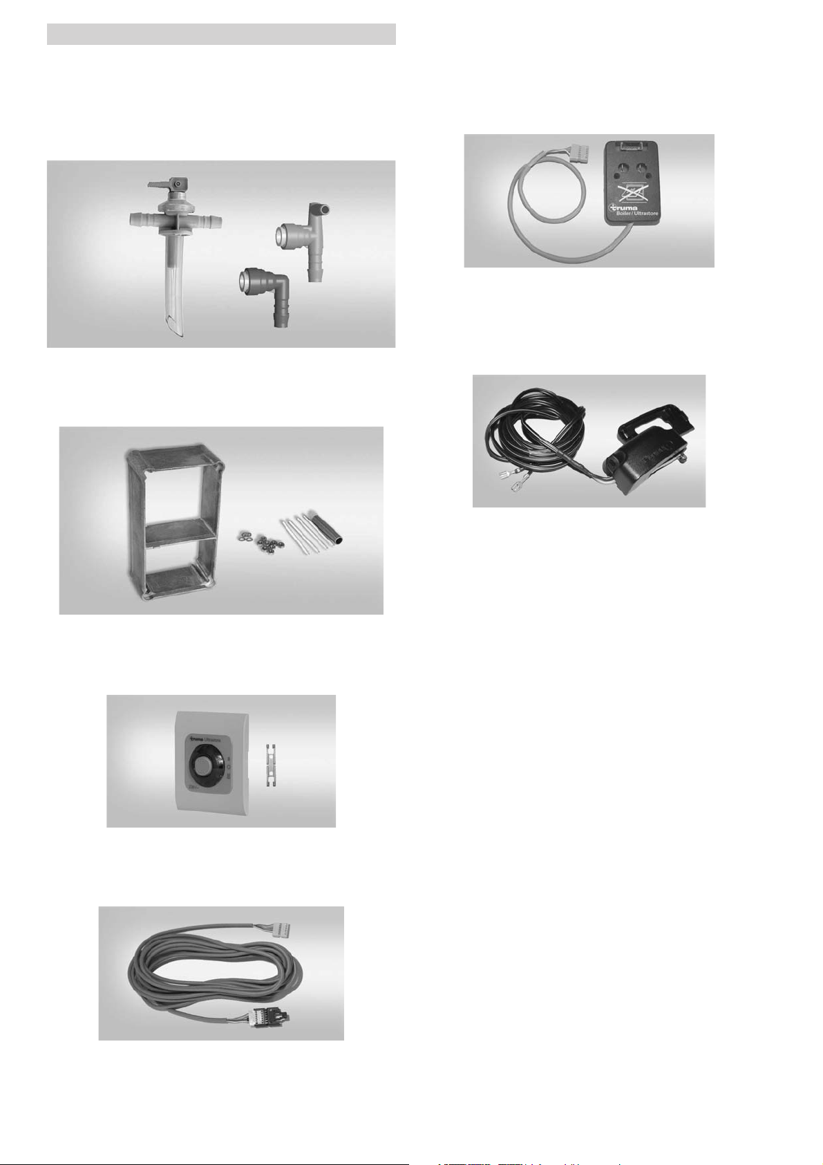
Accessories
Shut-off device
Safety/drain valve and water connectors for flexible
water hoses
34020-63900 Hot water connector, 10 mm
34020-16900 Cold water connector, 10 mm
70141-02 Safety/drain valve (4.5 bar), 10 mm
Cowl extension for wall thicknesses over 35 mm
70131-00 Cowl extension VBO 2
To use when the cowl is fitted under a opening part of a
window (only to use together with an appropriate window
switch).
70020-00800 Shut-off device
Window switch
To use together with the shut-off device (universal fitting)
34000-85800 Window switch
230 V Control panel for electrical operation
70020-35100 230 V Control panel
Control panel extension cable
70000-53500 Control extension 5 m
14
Page 15

Notes
Page 16

In Germany, always notify the Truma Service Centre
if problems are encountered; in other countries the
relevant service partners should be contacted (see
Truma Service Booklet or www.truma.com).
Having the equipment model and the serial number
ready (see type plate) will speed up processing.
Om · ©
70020-33900 · 04 · 11/2011 ·
Sales and Service in UK and Eire:
Truma (UK) Limited
2000 Park Lane, Dove Valley Park
Foston
South Derbyshire DE65 5BG
Service
telephone: (01283) 58 60 20
telefax: (01283) 58 60 29
[email protected]
www.trumauk.com
 Loading...