

Page 1

Truma Gerätetechnik GmbH & Co
Postfach 1252
D-85637 Putzbrunn
Service (Deutschland)
Telefon 0049 (0)89 4617-142
Telefax 0049 (0)89 4617-159
e-mail: [email protected]
Internet: www.truma.com
Service
(UK and Eire)
Telephone: (0 12 83) 51 10 92
Facsimile: (0 12 83) 53 21 28
Ultrastore
Gas and Electric
Storage Water Heater
Demandez le mode d’emploi et
les instructions de montage
dans votre langue au fabricant
Truma ou au service Truma de
votre pays.
Potete richiedere le istruzioni
d’uso e di montaggio nella Vostra lingua presso il produttore
Truma o il servizio di assistenza
Truma del Vostro Paese.
De gebruiks- en inbouwaanwijzing in Uw landstaal kan
bij de fabrikant Truma of bij de
Truma-service in Uw land worden aangevraagd.
De kan rekvirere brugs- og
monteringsvejledningen på
Deres sprog enten hos producenten Truma eller hos Trumaservicen i Deres land.
Die Gebrauchs- und Einbauanweisung in Ihrer Landessprache kann beim Hersteller
Truma oder dem Truma-Service
in Ihrem Land angefordert werden.
Operating instructions
Installation instructions
To be kept in the vehicle!
Page 1
Bruks- och monteringsanvisningar på svenska kan
rekvireras från tillverkaren
Truma eller från Truma-Service
i Sverige.
Návod k použití a montáži
ve svém jazyce obdržíte
na požádání u firmy Truma
nebo u jejího servisního
zástupce ve vaší zemi.
Käyttö- ja asennusohjeita on
saatavissa Truma-valmistajalta
tai Truma-huollosta.
Las instrucciones de uso y las
instrucciones de montaje en
el idioma de su país podrá solicitarlas del fabricante Truma
o del Servicio Truma
en su país.
A magyar nyelvü használati és
szerelési utasítást a gyártónál
a Truma cégnél vagy a Truma
magyarországi képviseleténél
lehet beszerezni.
Bruksanvisningen og
monteringsveiledningen på
ditt språk kan fås hos produsentenTruma eller hos TrumaService i ditt land
Instruções de utilizaçaõ e
instruções de montagem
podem ser solicitadas junto
ao fabricante Truma ou da
assistência técnica da Truma
no seu país
Instrukcję obsługi i montażu
w ojczystym języku mogą
Państwo dostać u producenta
(Truma) lub w serwisie Trumy
w swoim kraju.
Τις οδηγίες χρήσης και
τοποθέτησης στη µητρική
σας γλώσσα µπορείτε να τις
λάβετε απ τον κατασκευαστή
Truma ή απ το σέρβις Truma
στη χώρα σας.
Page 2

Installation example
1 Truma-Ultrastore
2 Control panel
3 Safety/drain valve
4 Cowl for combustion air intake
and exhaust gas discharge
US 2
Ultrastore
Gas and Electric
Storage Water Heater
1
2
4
3
Page 3

US 3
Ultrastore
Gas and Electric
Storage Water Heater
23
20
15
16
22
14
13
24
6
A
C
F
E
D
Direction of travel
12
23
20
15
16
22
14
13
24
B
Page 4
There shall be no claim under guarantee if this point
is not observed.
Always remove the cowl
cover prior to operating
the water heater!
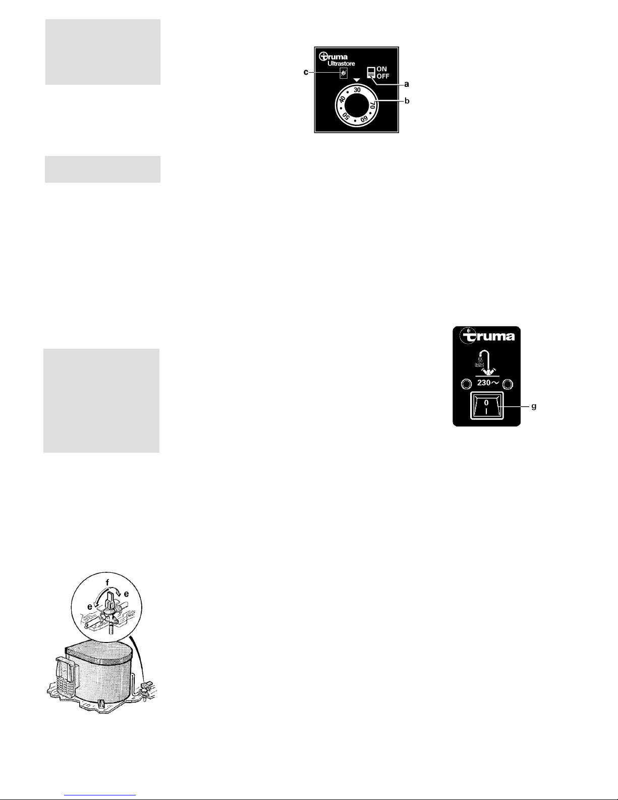
Red indicator lamp
„Failure“
The red indictor lamp (c)
lights up if there is a failure.
The reason for such an indication is, for example, no gas
available or air in the gas supply system, triggering of the
excess temperature monitor
etc. To unlock, switch off the
appliance, wait 5 minutes,
and switch on again.
In event of faults, always contact the Truma Service (please
refer to the last page)
Truma control panel
(Electrical operation
230 V, 450 W)
g = Switch, „On/Off“
When using the
vehicle switches
Refer to operating instructions of the vehicle manufacturer or see switch labels.
Electrical operating
instructions
Attention: Never operate the
water heater without water in
it!
Switch on at the control panel (g). The indicator lamp indicates that the electrical water
heating is switched on.
Attention: The water temperature cannot be selected, automatic temperature limitation at
approx. 70°C! For a faster heating up period the appliance can
be simultaneously operated
with gas and electrical power.
Note: The electrical heating
element is fitted with an excess temperature cut-out. In
the event of a fault, switch off
at the control panel, wait
5 minutes, then switch on
again.
Filling the TrumaUltrastore with water
1. Check that the safety/ drain
valve in the cold water intake
is closed: Lever should be in
horizontal position, position
(e).
2. Open hot tap in bathroom
or kitchen, with pre-selecting
mixing taps or single-lever fittings set to „hot“.
3. Switch on power for water
pump (main switch or pump
switch).
Leave the tap open to let air
escape while the water heater
is filling. The heater is filled
when water flows out of the
tap.
Residues of frozen water can
prevent filling if there is a
frost. The water heater can be
defrosted by switching on the
heater for a short period
(max. 2 minutes). Frozen
pipes can be defrosted by
heating the room.
Note: If just the cold water
system is being used, without
water heater, the heater tank
is also filled up with water. In
order to avoid damage
through frost, the water contents must be drained by actuating the safety/ drain valve,
also when the heater has not
been used. As an alternative,
two shut-off valves, resistant
to hot water, can be fitted in
front of the cold and hot water connection.
Draining the water
heater
1. Disconnect power for
water pump (main switch or
pump switch).
2. Open hot water taps in
bathroom and kitchen.
3. Open safety/drain valve:
Lever in vertical position, position (f).
4. The water heater is now
drained directly to the outside
via the safety/drain valve.
Check that the water contents have been completely
drained (10 litres).
Control panel
(Gas operation)
a = Slide switch „On/Off“
„Gas operation“
b = Rotary knob for water
temperature
(illuminated by green
lamp „Operation“)
c = Red indicator lamp
„Failure“
Gas operating
instructions
Attention: Never operate the
water heater without water in
it!
If the wall cowl is positioned
close to an opening window
(or hatch) - in particular directly under it - it must remain
closed when the water heater
is in use (see warning plate).
1. Remove cowl cover.
2. Open gas cylinder and
open quick-acting valve in the
gas supply line.
3. Select required water temperature at rotary knob (b) infinitely variable from approx.
30° to 70°C.
4. Switch on water heater at
the slide switch (a) on the
control panel, green indicator
lamp „Operation“ lights up.
5. If there is air in the gas
supply line, it may take up to
a minute before the gas is
available for combustion. If
the appliance switches to
„Failure“ during this period,
switch off the appliance wait 5 minutes - and switch
on again!
Switching off
(gas operation)
Switch off the water heater at
the slide switch (a).
Drain the water heater if
there is a risk of frost!
If the water heater is not to
be used for a longer period,
mount cowl cover (non-observance of this point can
lead to the function of the appliance being impaired
through water, dirt or insects), close quick-acting
valve in the gas supply line
and close the gas cylinder.
1
Truma-Ultrastore
liquid gas storage
water heater with
additional electric
heating 230 V
Operating
instructions
Always observe the operating instructions prior to
starting! The vehicle owner
is responsible for the correct
operation of the appliance.
The installer or vehicle owner
must apply the yellow sticker
with the warning information,
which is enclosed with the
appliance, to a place in the
vehicle where it is clearly visible to all users (e.g. on the
wardrobe door)! Ask Truma to
send you stickers, if necessary.
Attention: Before using for
the first time, it is essential to
flush the entire water supply
through with clean warm water. Always mount the cowl
cap when the water heater is
not being operated! Drain the
water heater if there is a risk
of frost! There shall be no
claims under guarantee for
damaged caused by frost!
When connecting to a central
water supply (rural or city
connection) or when using
more powerful pumps, a
pressure reducer must be
used which prevents pressures of greater than 2.8 bar
occurring in the Ultratore.
Safety/drain valve
e = Lever position
„Closed"
f = Lever position
„Drain"
Page 5
2
Maintenance
Note: The water tank in the
Truma-Ultrastore is made of
high quality food-proof stainless steel VA.
Use wine vinegar for de-scaling the water heater, this being introduced into the appliance via the water supply. Allow the product to react and
then thoroughly flush out the
appliance with plenty of fresh
water. To sterilise the water
we recommend „Certisil-Argento”. Other products, particularly those containing
chlorine are unsuitable.
In order to avoid the proliferation of micro-organisms, heat
the Ultrastore to 70°C at regular intervals.
Do not use the water as
drinking water!
Fuses
The water heater fuse is on
the electronic control unit on
the water heater.
Important note: Only replace the miniature Fuse on
the p.c.b. with a fuse of the
same type: 1.6 AT
EN 60127-2-3 (slow action).
If there is a defect in the electronics, return the control
p.c.b. well padded. If you fail
to pack it correctly the guarantee shall no longer be valid.
Only use original Truma-Ultrastore control p.c.b.'s as spare
parts!
while. Remedial action here
is to immediately run the
heater and to ensure adequate room ventilation.
7. Items sensitive to heat
(e.g. spray cans) must not be
stored in the installation area,
since excess temperatures
may under certain circumstances be incurred there.
8. If the burner makes an unusual noise or if the flame
lifts off, it is likely that the
regulator is faulty and it is
essential to have it checked.
9. For the gas system, only
gas pressure regulators with
protection against excess
pressure, such as regulators
with safety valves according
to DIN 4811 and VP 306, may
be used. We recommend the
Truma DUB vehicle regulator
or in the case of a two cylinder gas installation that is
only accessible from the outside, the Truma Triomatic automatic reserve switch-over.
The Truma regulators have
been specially designed for
heavy duty use in caravans,
boats and vehicles. In addition to a safety valve for
countering excess pressure,
they also have a pressure
gauge with which you can
check that the installation is
fully gas tight.
Always connect the pressure
regulators to the gas cylinders by hand, using great
care! For temperatures
around 0°C and below, the
regulators should be operated with a defroster system
(Eis-Ex). Inspect regulator
connection hoses regularly
for signs of weakness.
For winter operation only use
special frost-resistant hoses.
Gas cylinders must always
stand upright!
General safety
notes
In event of leaks in the gas
system or if there is a smell of
gas:
- extinguish all naked
flames!
- do not smoke!
- switch off the appliances!
- close gas cylinder!
- open the windows!
- do not operate any
electrical switches!
- have the entire system
checked by an expert!
Repair jobs are only
to be carried out by
an expert.
1. Any alteration to the appli-
ance (including cowl) or the
use of spare parts and accessories which are important for
the functioning of the heater
and which are not original
Truma parts, as well as the
non-observance of the installation and operating instructions, shall lead to the cancelling of the guarantee and
exclusion of liability claims. It
also becomes illegal to use
the appliance, and in some
countries this even makes it
illegal to use the vehicle.
2. The operating pressure for
the gas supply is 30 mbar (or
28 mbar butane/37 mbar
propane) and must correspond to the operating pressure of the appliance (see data plate).
3. In Germany only LPG
systems must comply with
the DVGW form G 607.
The gas system must be
tested every 2 years by a
liquid gas expert (DVFG, TÜV,
DEKRA). This inspection must
be confirmed on the test certificate in accordance with
the DVGW-form G 607.
The vehicle owner is always responsible for arranging the inspection.
4. In other countries, the
respectively valid regulations
must be observed. For your
own safety it is absolutely
necessary to have the complete gas installation regularly
checked by an expert (at least
every 2 years).
5. Do not operate the water
heater when refuelling the vehicle and when in the garage.
6. During the initial operation
of a brand new appliance (or
after it has not been used for
some time), a slight amount
of fumes and a slight smell
may be noticed for a short
Technical data
Water contents: 10 litres
Water pressure:
up to max. 2.8 bar
Type of gas:
Liquid gas (propane/butane)
Operating pressure:
30 mbar (or 28 mbar butane/
37 mbar propane)
Rated thermal output:
1500 W
Gas consumption: 120 g/h
Heating time
up to approx. 70°C
Gas operation: approx. 35 min.
electrical operation:
approx. 70 min.
Gas and electrical operation:
approx. 20 min.
Power consumption 12 V
Ignition: 0.17 A
Heating up: 0.08 A
Standby: 0.04 A
Power consumption 230 V
Heating up: (2 A) 450 W
Weight (empty):
approx.: 6.7 kg
Declaration of conformity:
The Truma-Ultrastore model
has been tested and approved through the DVGW
and fulfils the EC gas appliance guidelines (90/396/EEC)
as well as the associated EC
guidelines. The CE product
number is available for EU
countries: CE-0085AP0038
Page 6

3
Installation
instructions
Please fold out page
with diagrams!
Installation and repair are
only to be carried out by
an expert. Always read and
follow the operating instructions carefully prior to starting
any work!
Intended use
This appliance has been designed for the installation in
caravans, mobile homes and
other vehicles. It is not approved for installation in
boats. Other forms of use are
also possible following consultation with Truma.
Information regarding boats:
For installation in boats Truma
supplies the DVGW-tested
boat water heater.
Approval
Declaration of conformity:
The Truma water heater model has been tested and approved through the DVGW
and fulfils the EC gas appliance guidelines (90/396/EEC)
as well as the associated EC
guidelines. The CE Ident.
Number is available for EU
countries: CE-0085AP0038
Regulations
Any alteration to the appliance (including cowl) or the
use of spare parts and accessories which are important for
the functioning of the heater
and which are not original
Truma parts, as well as the
non-observance of the installation and operating instructions, shall lead to the cancelling of the guarantee and
exclusion of liability claims. It
also becomes illegal to use
the appliance, and in some
countries this even makes it illegal to use the vehicle.
The operating pressure for
the gas supply is 30 mbar
(or 28 mbar butane/
37 mbar propane) and
must correspond to the
operating pressure of the
appliance (see name plate).
When installing the appliance always observe the
technical and administrative rules and regulations
of the country in which the
vehicle is to be registered,
for the first time!
In Germany, for example, gas
appliances, cylinder mounting, duct routing as well as
the approval and leak test
must comply with the DVGW
form G 607 for liquid gas systems in vehicles.
Ask for more details con
cerning regulations in the
respective countries from
our agencies abroad (see last
page).
1
Choice of location
1. Always install the appliance in such a way that it is
easily accessible for service
work at all times and can be
easily removed and installed.
2. Locate the heater in such a
way that the cowl can be
mounted on the outside on a
surface which is as straight
and smooth as possible.
This outside surface must be
exposed to wind from all directions and, if possible, there
should be no trim strips or
covers in this area, mount
heater on an appropriate
base, if necessary.
The cowl must be placed in
such a way that the exhaust
gas cannot find its way into
the vehicle interior. For this
reason, choose a location
where there are no opening
windows, skylights or ventilation openings directly above
the cowl or for 30 cm on either side. If this is not possible, a warning plate must be
placed on the inside of the
window (or skylight) stating
that it must be kept closed
while the heater is operating.
In this case refrigerator ventilations must be tight-sealed
from the interior of the vehicle.
2
Installation of the
water heater
1. Position template for cowl
opening on the inside of the
wall.
A = bottom edge of heater
B = lateral edge of heater
Drill 4 holes (C) with 10 mm
dia. through the wall. Drill
hole (E) with 15 mm dia. for
condensation pipe (also possible from the outside = F).
2. Position template on the
outside of the wall. The markings (C) must be above the
through-holes. Saw cut-out
section for cowl (D)
92 x 168 mm.
If the distance between outside wall and heater is more
than 35 mm you must use
the cowl extension VBO 2
(Art. no. 70131-00) with an
additional length of 50 mm.
Saw out 100 x 176 mm along
the dashed line.
If there are any cavities in the
area of the cowl (Fig. A: 1),
pack these with pieces of
wood so as to be able to
tighten the screws.
Cut out trim strips or such on
the vehicle or place supports
beneath them so as to make
the cowl lie flat.
Place a support beneath the
heater if the walls are sloping.
An angle of inclination of 10
degrees is not to be exceeded.
3. Fig. A: Insert heater with
cowl body (3) through the
cowl opening (1), allow approx. 5 mm to project out of
the wall. Mount sealing frame
(4) (the anti-torsion device ensures correct fitting!). Pre-drill
holes for the 6 fastening bolts
(5).
4. Remove sealing frame (4)
and coat with plastic sealant
on the side facing the vehicle
- do not use silicone!
Attention: The sealing frame
must be well sealed with respect to the front sides and
the cross bars of the cowl
body (3) as well as towards
the outside wall!
5. Fasten sealing frame (4) to
the cowl body using 4 selfcutting screws (7).
6. Seal the gap between the
hole (2) and the condensation
tube (10) with plastic sealant
- do not use silicone!
7. Mount the grille (8). Press
the entire cowl assembly onto the vehicle wall and fasten
with 6 screws (5).
8. Screw the boiler securely
to the floor of the vehicle with
at least two shackle plates
(11) with the screws provided, B 5.5 x 25, on a suitable
base (plywood panel, laminated wood strips, or metal
base).
3
Water connection
All pressure and submergible
pumps up to 2.8 bar are used
for operating the water heater
and all mixed combination
sets with or without an electrical switch.
Fig. B: When using immersion pumps, a non-return
valve (12 - not included in the
scope of supply) must be fit-
ted between the pump and
the first branch point (arrow
points in direction of flow).
Fig. C: When using pressure
pumps with high switching
hysteresis, hot water may
flow back through the cold
water tap. To prevent the
backflow, we recommend
that a non-return valve (6 not included in the scope of
supply) be fitted between the
outlet to the cold water tap
and the drain valve.
Pressure and hot water-resistant hoses (e.g. Truma boiler
hose SBH, food-safe, pressure resistant up to 3.5 bar)
with an internal diameter of
10 mm should be used for
the boiler and the safety/drain
valve connections.
For fixed pipe routing (e.g.
John Guest System) Truma
can provide the water connectors (15 + 16), the safety/
drain valve (13) and a non-return valve (12 + 6) with a
straight 10 mm diameter tap
connector as special accessories.
If connecting to a central water supply (rural or city connection) or when using more
powerful pumps, a pressure
reducer must be used which
prevents pressures of greater
than 2.8 bar occurring in the
boiler.
Attention: Route the water
hoses so that they are as
short and free of kinks as
possible. All hose connections must be secured using
hose clamps (also for cold
water)! Pressures of up to
3.5 bar can occur in the safety/drain valve (also in submergible pumps) because of
the heat of the water and the
resulting expansion.
Hose clips (Art. no. 40710-00)
are recommended for attaching the hoses to the wall or
the floor. If gas heating has
been installed, the water
hoses and the hose clips can
be laid on the hot air pipes,
which prevents frost.
Attention: In order to guarantee that the Ultrastore is
completely empty, the enclosed elbow with breather
valve (figure d: 15) must be
used for the hot water connection!
All hot water pipes should
be routed in a descending
manner to the safety/drain
valve! Otherwise no guarantee of protection from
frost!
Page 7
4
Installation of the
safety/drain valve
Fig. B + C: Install safety/drain
valve (13) at a place which is
easily accessible, near the
water heater. Drill hole with
18 mm diameter and pass
through discharge socket
with hose (14). Fasten safety/
drain valve with 2 screws.
The draining is to be directly
to the outside at a position
protected against splash water (apply splash guard, if
necessary).
Water pipe routing
1. Fig. B + C: Connect cold
water supply (24) to safety/
drain valve (13). Direction of
flow is unimportant.
2. Fig. D: Screw elbow with
integrated breather valve (15)
to hot water connection pipe
(upper pipe) and elbow without breather valve (16) to cold
water connecting pipe (lower
pipe).
Slide on nut (17), tension ring
(18) and O-ring (19). Assemble screw connector and connecting pipe and fasten together using nut (17).
Slide ventilation hose with
11 mm outer diameter (20)
onto the breather valve hose
nozzle (21) and route towards
the outside. Do not allow the
radius of the arc to be less
than 40 mm.
Cut off the ventilation hose
approx. 20 mm below the
floor of the vehicle at an angle of 45° to the direction of
travel.
3. Fig. B + C: Produce hose
connection (22) for cold water supply between safety/drain valve (13) and elbow
(16 - lower pipe) on water
heater.
4. Route the hot water pipe
(23) from the elbow with integrated breather valve (15 upper pipe) to the hot water
consumers.
4
Installation of the
control panels
Attention: When using con-
trol panels which are specific
to the vehicle or the manufacturer, the electrical connection must be established in
accordance with the Truma
interface descriptions (refer to
Electrical connection 230 V).
Any modification made to the
Truma components pertaining
to this will lead to the invalidation of the guarantee, as
well as to the exclusion of any
claims for liability. The installer
(manufacturer) is responsible
for providing instructions for
use for the user as well as for
identification printing on the
control panels.
When selecting the location,
bear in mind that the control
panels must not be subjected
to direct radiant heat. Length
of connection cables 2.5 m.
Control panel,
gas operation
If required, for the gas operation control panel a cable extension of 5 m can be supplied (Art. No. 70000-53500).
1. Pass control panel cable
through the cable binder on
the back of control panel.
Connect cable to the control
panel and tighten cable
binder as strain relief.
Fasten control panel using
2 screws and route the cable
to the water heater.
Note: Depending on the installation, the routing of the
control panel cable can be
done in the other way. This
means first connect to the
water heater and then route
to the control panel.
Truma control panel,
electrical operation
Fig. E: When selecting the
place of location, always
make sure that the control
panel (27) is not exposed to
direct heat radiation.
Drill a hole with 8 mm diameter for leading through the
cable and pass the cable
through the hole. Fasten control panel with the two
screws and route the cable to
the appliance.
5
Electrical
connection 12 V
Always disconnect the appliance from the power
supply prior to working on
electrical components. It is
not sufficient to just
switch off at the control
panel!
The appliance must be disconnected from the vehicle
main power supply when carrying out any electric welding
work on the vehicle body.
Attention: If the connections are transposed there
is a risk of cable burning.
This also rules out any
guarantee or liability
claims.
Fig F: Unscrew cover (34)
from the electronic control
unit. Slide cable connector of
control panel (28) onto the
p.c.b.. The electrical connection is made at terminal (35)
(red = positive, blue = negative), for this purpose press
with a small screwdriver from
above and push in cable from
the front. Connect to fused
vehicle mains (central electrical equipment 5 - 10 A) using
a 2 x 1.5 mm
2
cable.
Negative cable to central
earth. With lengths of over
6 m use a cable 2 x 2.5 mm
2
.
If connecting directly to the
battery, the positive and negative cable must be fused.
Screw cover (34) back on.
There are to be no other consumers connected to the supply line!
The water heater fuse,1.6 A
EN 60127-2-3 (slow-acting) is
on the p.c.b. (36).
When using power packs, observe that the appliance is only to be operated with safety
extra-low voltage according
to EN 60742!
Note: For the connection of
several 12 V appliances we
recommend the electronically
controlled Truma power pack
NT (Art. no. 39900-01). The
Truma power pack (6 A continuous current) is also suitable for charging lead batteries. Other charging devices
are only to be used with a car
battery acting as buffer. Power packs and power supply
units must have a stabilised
12 V-output (ripple content
less than 1 Volt).
6
Electrical
connection 230 V
Attention: The electrical con-
nection is only to be carried
out by an expert (in Germany,
acc. to VDE 0100, Section
721). The information given
here is not intended as information for the layman, rather
it is to for assisting the assigned expert, as additional
information, when connecting the appliance!
The connection to the power
supply is by means of a cable
3 x 1.5 mm
2
(e.g. flexible
sheathed cable H05VV-F) to a
splitting box (not included in
scope of delivery).
Always pay attention to connect carefully with the correct
colours!
For maintenance and repair
work a disconnecting device
must be provided on the vehicle for all-pole disconnection
from the power supply, with
at least 3 mm contact clearance.
Connection 230 V with
Truma control panel
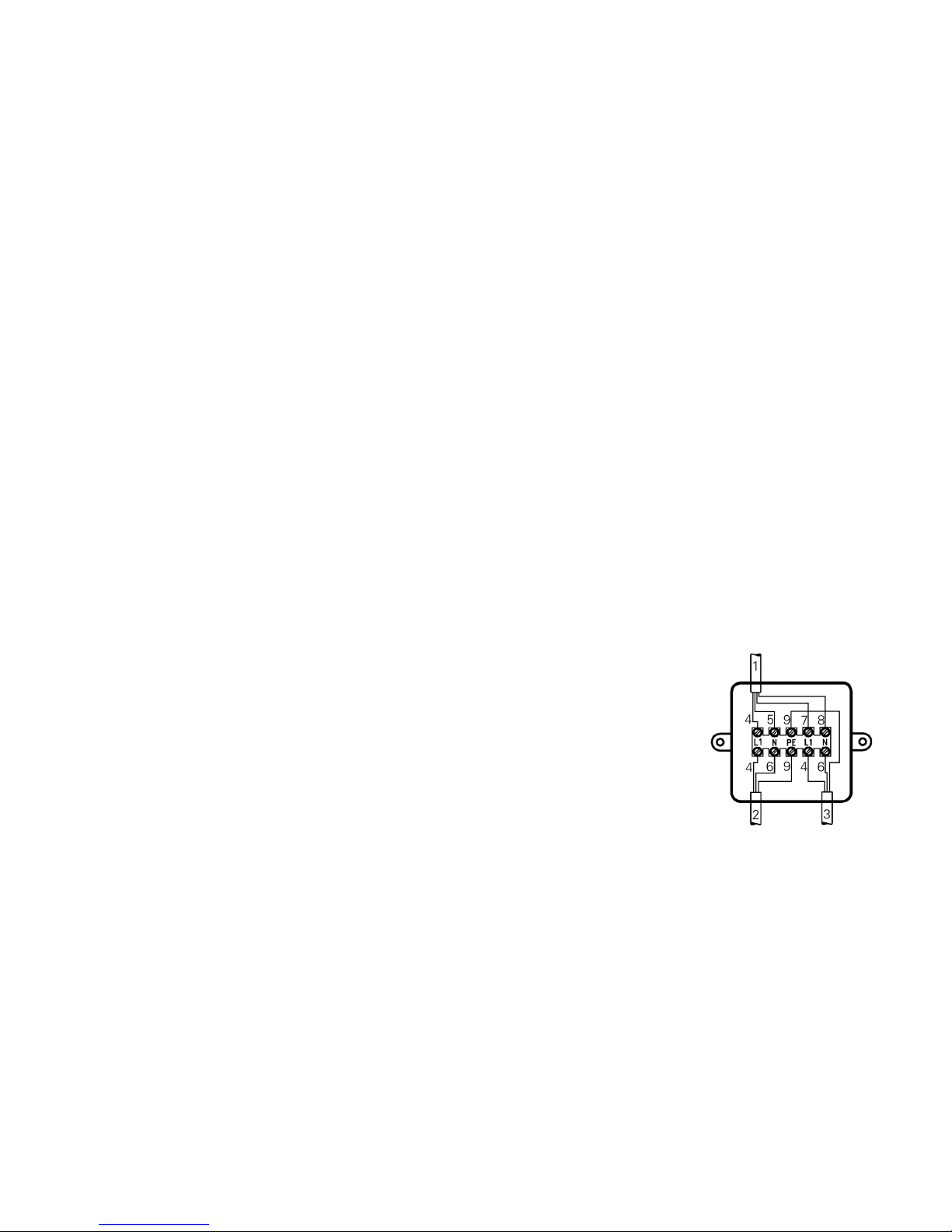
1. Connect control panel cable, supply line 230 V and
heating element cable as
shown in the drawing.
1 = Control panel cable
2 = Supply line 3 x 1,5 mm
2
3 = Heating element cable
4 = brown
5 = green
6 = blue
7 = yellow
8 = white
9 = yellow/green
2. Assemble the splitting box
(Fig. E: 37) on the vehicle
floor or on the wall, in the
vicinity of the appliance (observe cable length 150 cm!).
Note: All cables must be
secured with cable clips.
Page 8
Manufacturer’s
terms of warranty
1. Case of warranty
The manufacturer grants a
warranty for malfunctions in
the appliance which are
based on material or production faults. In addition to this,
the statutory warranty claims
against the seller remain
valid.
A claim under warranty shall
not pertain:
- for parts subject to wear and
in cases of natural wear and
tear,
- as a result of not original
Truma parts being used in
the appliance and as a result
of unsuitable gas pressure
regulators being used,
- as a consequence of failure
to respect Truma instructions for installation and use,
- as a consequence of improper handling,
- as a consequence of improper transport packing,
not arranged by Truma.
2. Scope of warranty
The warranty is valid for malfunctions as stated under
item 1, which occur within
24 months after conclusion of
the purchase agreement between the seller and the final
consumer. The manufacturers
will make good such defects
by subsequent fulfilment, i.e.
at their discretion either by repair or replacement. In the
event of manufacturers providing service under warranty,
the term of the warranty shall
not recommence anew with
regard to the repaired or replaced parts; rather, the old
warranty period shall continue
to run. More extensive claims,
in particular claims for compensatory damages by purchasers or third parties, shall
be excluded. This does not affect the rules of the product
liability law.
The manufacturer shall bear
the cost of employing the
Truma customer service for
the removal of a malfunction
under warranty - in particular
transportation costs, travelling
expenses, job and material
costs, as long as the service
is carried out in Germany.
Customer service carried out
abroad is not covered by the
warranty.
Additional costs based on
complicated removal and installation conditions of the
appliance (e.g. removal of
furniture or parts of the vehicle body) do not come under
warranty.
3. Raising the case of
warranty
The address of the manufacturers is: Truma Gerätetechnik GmbH & Co. KG, Wernher-von-Braun Strasse 12,
D-85640 Putzbrunn. In Germany, in the event of faults,
in principle the Truma Service Centre at the manufacturers' address is to be notified; abroad, respective service partners are available
(refer to address list). Complaints must be specified. In
addition, the correctly completed warranty certificate
must be presented or the Serial number of the appliance
and the date of purchase
specified.
In order for the manufacturers to be able to determine
whether an incident subject
to guarantee has occurred,
the end user must, at his
own risk, bring the device to
the manufacturers or send it
to them. If there is damage
to heaters (heat exchangers),
the gas pressure regulator
must also be sent back to
the factory.
In instances of the device being sent to the works, dispatch is to be effected by
freight transport. In cases
under guarantee, the works
shall bear the transport costs
or the costs of delivery and
return. If the damage is
deemed not to be a warranty
case, the manufacturer shall
notify the customer and shall
specify repair costs which
shall not be borne by the
manufacturer; in this case,
the customer shall also bear
the shipping costs.
5
Conection 230 V
with specific vehicle
or manufacturer
control panels
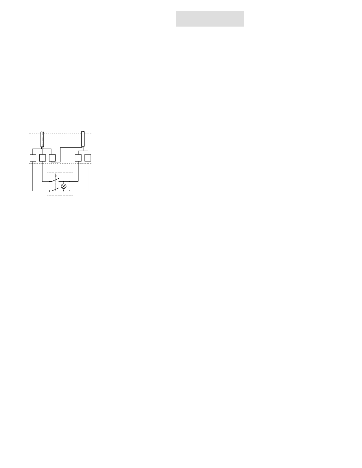
Connect control panel cable,
230 V cable and heating element cable as shown in the
drawing.
Cables must be in accordance with the technical rules
and regulations of the country in which the vehicle is to
be registered, for the first
time (e.g. in Germany VDE
0100, section 721).
7
Gas connection
Fig. A: The 8 mm gas supply
line is connected to the connection nozzle (38) with cutting ring connection. The cutting rings are to be selected
according to the gas pipe
used (for copper pipe: support sleeves and brass cutting
ring as supplied). Carefully
hold in place with a second
wrench when tightening!
Before connecting to the water heater make sure that the
gas lines are free from dirt,
chips and such!
Route the pipes in such a way
that the appliance can be removed again for servicing.
In areas frequented by people, keep the number of parting connections in the gas
supply line to an technically
feasible minimum.
The gas system must comply
with the technical and administrative regulations of the
country in which the appliance is used (in Germany, for
example, the DVGW form
G 607).
supply line
230 V
3 x 1,5 mm
2
heating
element
splitting box
control panel
PEL
N
N’ L’
8
Function check
After installation, check gas
supply line for leaks in accordance with the pressure drop
method. Following this,
check the function of the appliance as specified in the operating instructions, check
the function of the draining of
the water contents, in particular. There shall be no
claims under guarantee for
damage caused by frost!
Never operate the water
heater without water contents. It is, however, possible
to briefly check the electrical
function without water contents. Always observe the operating instructions prior to
operation!
The operating instructions
and completed guarantee
card are to be given to the
owner of the vehicle.
9
Warning information
The installer or vehicle owner
must apply the yellow sticker
with the warning information,
which is enclosed with the
appliance, to a place in the
vehicle where it is clearly visible to all users (e.g. on the
wardrobe door)! Ask Truma to
send you stickers, if necessary.
Page 9
✂
Guarantee Card
Garantie-Karte
Bon de Garantie
Certificato di Garanzia
Garantiebon
Garantikort
Tarjeta de garantía
International Service
Germany:
Truma Gerätetechnik GmbH & Co,
Putzbrunn (Munich)
Tel. (089) 46 17-142
Great Britain:
Truma (UK) Ltd.,
Burton Upon Trent,
Tel. (01283) 55 82 01
Greece:
G. Bournas - G. Efthimiou O.E.,
Athen, Tel. (010) 346 14 14
Hungary:
Virág Trans Bt.,
Budapest, Tel. (01) 263 14 66
Iceland:
Afl-Húsbílar ehf.,
Akureyri, Tel. (0462) 79 50
Italy:
Dimatec S.p.A.,
Guanzate, Tel. (031) 352 90 61
Japan:
Carac Industry Co., Ltd.
Tokyo, Tel. (03) 39 31 02 20
Australia:
Dometic Pty Ltd.,
Victoria, Tel. (03) 95 45 56 55
Austria:
Globus Mobil Park,
Wörschach, Tel. (03682) 241 60
K. Hofer Ges.m.b.H. & Co KG,
Wien, Tel. (01) 715 11 75
Wohnwagen-Pusch,
Gmunden, Tel. (07612) 67 94 50
Belgium:
Gautzsch Gimeg N.V.,
Aalst, Tel. (053) 70 66 77
Czech Republic:
KOV, Karosárna a slévárna,
Velim, Tel. (0321) 76 35 58
Danmark:
A.C. Lemvigh-Müller,
Kopenhagen, Tel. (03311) 05 32
Finland:
Kehä Caravan Tukku Oy,
Espoo, Tel. (09) 84 94 30 34
France:
Euro Accessoires,
Tournon, Tel. (04) 75 06 92 92
Luxembourg:
Ets. Geiben s.à.r.l.,
Belvaux, Tel. 59 15 19
Netherlands:
Gautzsch Gimeg B.V.,
De Meern (Utr.), Tel. (030) 662 95 22
Norway:
Neptus A.S.,
Vollen, Tel. (6675) 99 50
Poland:
Truma Polska Sp. z o.o.,
Kraków Tel. (012) 641 02 41
Portugal:
J.C.L. Andrade, Lda.,
Feira Codex, Tel. (025) 680 10 34
Marcampo Lda.,
Lisboa, Tel. (021) 848 67 76
Russia:
Companija Poliauto,
Moskau, Tel. (095) 232 00 39
Slowakian Republic:
Tamex spol. s r.o.,
Bratislava Tel. (02) 44 45 49 20
Slowenia:
Prebil d.o.o.,
Ljubljana, Tel. (061) 542 63 70
Spain:
Stimme, S.L.,
Massalfassar (Valencia),
Tel. (0961) 40 00 58
Sweden:
Alde International Systems AB,
Färlöv, Kristianstad,
Tel. (044) 712 74
Switzerland:
Selzam AG,
Winterthur, Tel. (052) 233 25 21
Turkey:
Karyat Karavan Yat San. Tic. Ltd.,
Istanbul, Tel. (0216) 418 73 96
White Russia:
Tachograph Ltd.,
Minsk, Tel. (017) 22 66 82 02
Page 10
Quality with tradition
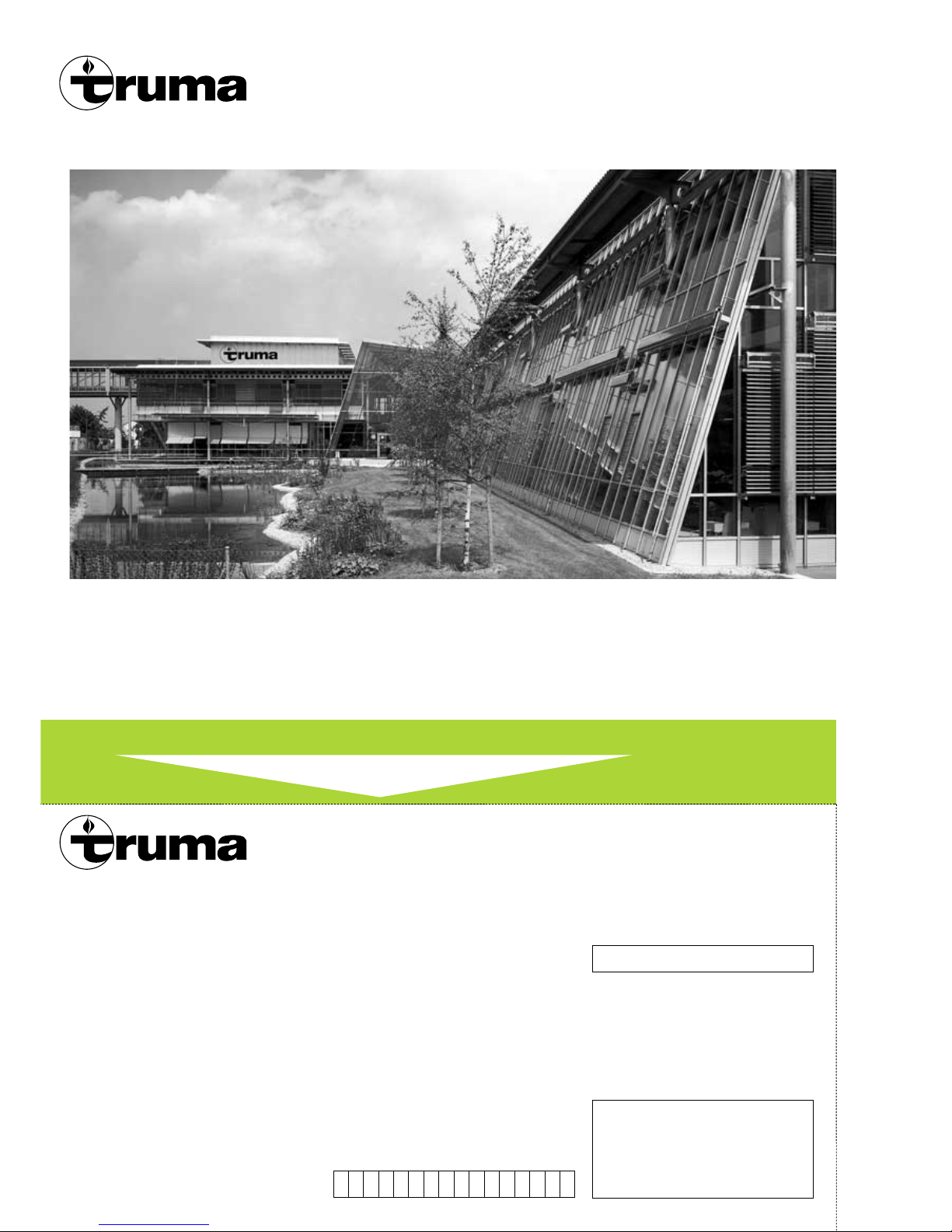
Truma was founded in 1949
and has since become the
leading European manufacturer of vehicle and boat
liquid gas heaters.
The entire programme of
Truma products is designed to
run on clean liquid gas fuel.
Using the knowledge gained
from practical experience,
over the years Truma has
developed warm air systems,
storage water heaters, air
conditionings, lamps, pressure regulators and accessories for Caravans and mobile homes and therefore decisively influenced the development of the camping scene
as a whole.
Today Truma is the internationally acknowledged brand
leader, operating on the basis
of the certified quality management system according to
ISO 9001.
✂
To be filled in by the dealer.
Date of sale
Verkaufsdatum
Date de vente
Data di vendita
Verkoopdatum
Salgsdato
Fecha de venta
03/02 · Truma, Postfach 1252, D-85637 Putzbrunn
Guarantee Card
Garantie-Karte
Bon de Garantie
Certificato di Garanzia
Garantiebon
Garantikort
Tarjeta de garantía
Serial number
Fabrik-Nummer
No. de fabrication
No. di matricola
Serie-nummer
Seriennummer
Número de fábrica
Ultrastore
Dealer’s address
Händler-Adresse
Adresse du commerçant
Timbro del rivenditore
Dealeradres
Forhandleradresse
Dirección del comerciante
70000-94600 · 02 · 03/02 · 17’B+W · ©
 Loading...