

TRUlink 40481 User Manual

1
U
SER GUIDE
MULTI-FUNCTION CONVERTER
Model: 40481

1
Introduction....................................................................................................................................................2
Features........................................................................................................................................................3
Package Contents.........................................................................................................................................4
Device Overview...........................................................................................................................................5
Device Installation to a Display for TV Function............................................................................................6
Device Installation to a PC and Display........................................................................................................8
Device Installation Using a Component Video Connection.........................................................................10
Device Installation Using a Composite Video Connection..........................................................................11
Example Application Diagrams...................................................................................................................12
Remote Control Functions..........................................................................................................................13
Favorite Channel Operation........................................................................................................................21
Troubleshooting...........................................................................................................................................23
Technical Specifications..............................................................................................................................24
Warranty.....................................................................................................................................................25
Important Safety Information.......................................................................................................................26
TABLE OF CONTENTS

2
Thank you for purchasing the TruLink™ Multi-Function Converter. With this device you make your PC
monitor a dual-purpose screen for both computer and TV video. The Converter accepts component or
composite video signals and upconverts them to VGA. Connect a cable television feed and watch television
programs on your computer monitor. Picture-In-Picture (PIP) allows you to watch content on your monitor in
a separate window while surfing the internet, paying bills or doing school work. The pass-through function
sends VGA video directly to the monitor from your computer when the Converter is powered down. MTS
stereo output via a 3.5mm stereo jack is compatible with Dolby Pro-Logic™ for a complete theater
experience. We recommend that you read this manual thoroughly and retain for future reference.
INTRODUCTION

3
Converts composite video or component video to VGA
125 channel cable ready tuner
Display home theater sources, gaming systems and camcorders on your flat panel
Use in a school dorm to turn you standard PC monitor into a television
Output resolution up to 1920 x 1200 for 24 bit RGB true color
Plug-n-Play, no software required
FEATURES

4
Multi-Function Converter (1)
Remote Control (1)
Unit Stand (1)
3ft. Video cable (HD15 to 8-pin din) (1)
6ft. 3.5mm Stereo Audio M/M cable (1)
Power Supply
PACKAGE CONTENTS
5
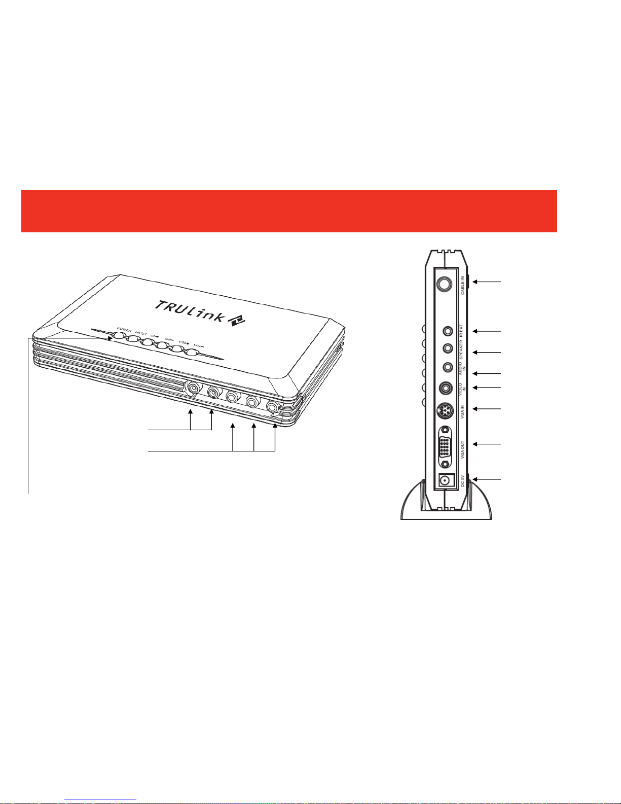
DEVICE OVERVIEW
Component Video
Input
Audio Input
Rear View
CATV Input
IR Extender Port
3.5mm Speaker
Output
3.5mm Audio Input
RCA Video Input
VGA Input
VGA Output
5V DC Power
Input
POWER: Turns the Multi-Function
Converter On and off
INPUT: Toggles through the device
inputs
CH+ -: Changes the CATV channel
up and down
VOL+ -: Changes the speaker
volume up and down

6
S
TEP 1
Place your Multi-Function Video Converter near your display.
S
TEP 2
Connect the CATV cable to the “CABLE IN” jack on the back panel.
S
TEP 3
Connect the monitor’s VGA cable to the “VGA OUT” jack on the back panel of the Multi-Function Converter.
Tighten the screws as a loose connection can cause picture distortion.
S
TEP 4
Connect your multimedia (computer) speaker (please note the connector should be 3.5mm male stereo
type) to “SPEAKER” on the back panel.
S
TEP 5
Connect the supplied 3.5mm audio cable to the speaker output of your PC sound card and the opposite end
to the “AUDIO IN” on the back panel of the Multi-Function Converter.
S
TEP 6 (OPTIONAL)
Connect an IR receiver extender to the “IR EXT” on the back panel of the Multi-Function Converter, and
route the emitter to an exposed area to receive signal from the remote.
DEVICE INSTALLATION TO A DISPLAY FOR TV FUNCTION
7
STEP 7
Connect the supplied AC/DC adapter to “DC 5V” on the back panel of the Multi-Function Converter and plug
the other end into an AC outlet.
S
TEP 8
Turn on your monitor and then push the “POWER” key on the Multi-Function Converter. You should have a
TV image on your LCD or CRT screen. Turn off the Multi-Function Converter and your computer should be
displayed.
DEVICE INSTALLATION TO A DISPLAY FOR TV FUNCTION
LCD or PDP
S
p
eakers
CATV
Back View
IR Extending Receiver (optional)
Power Su
pply

8
S
TEP 1
Connect the RF cable for the CATV to “CABLE IN” on the Multi-Function Converter.
S
TEP 2
Connect a VGA cable from your display to the “VGA OUT” on the back panel of the Multi-Function Converter.
Take the supplied VGA cable and connect the 8-pin end into the “VGA IN” on the back panel of the
Multi-Function Converter and connect the HD15 (VGA) connector to your PC.
S
TEP 3
Connect your speakers to the “SPEAKER” output on the back panel of the Multi-Function Converter.
Take the 3.5mm to 3.5mm audio cable, and connect one end to the “AUDIO IN” on the back panel of the
Multi-Function Converter, and the other end to your PC.
DEVICE INSTALLATION TO A PC AND DISPLAY
 Loading...