

Page 1

Network Time Server
IRIG NTS-100
600-201
SERIAL NUMBER_______________
Revision A
January 20, 1997
Page 2

NTS-100 Network Settings
Record NTS-100 network settings below for quick reference.
NTS-100 network setup instructions are detailed in Section 3.
Ethernet Address: ____________________________________
IP Address: ____________________________________
Subnet Mask: ____________________________________
Default Gateway: ____________________________________
Network Type: ____________________________________
Clock Type: ____________________________________
Page 3

SECTION I 1-1
GENERAL INFORMATION 1-1
1.1 INTRODUCTION 1-1
1.2 LIMITED WARRANTY 1-1
1.3 LIMITATION OF LIABILITY 1-2
1.4 PROPRIETARY NOTICE 1-2
1.5 PHYSICAL SPECIFICATIONS 1-2
1.6 ENVIRONMENTAL SPECIFICATIONS 1-2
1.7 POWER INPUT SPECIFICATIONS 1-2
1.8 NTS-100 SYNCHRONIZATION OPTIONS 1-3
1.9 INTERNAL TIMING PERFORMANCE SPECIFICATIONS 1-3
1.10 NETWORK TIME PROTOCOLS 1-3
1.11 NETWORK TIME PROTOCOL SYNCHRONIZATION SPECIFICATIONS 1-4
1.12 INTERFACE SPECIFICATIONS 1-5
Ethernet Interface 1-5
User RS-232 Serial I/O Interface 1-5
LED Status Indicator 1-6
Optional Time/Frequency Output Signals 1-6
IRIG B Time Code 1-6
1 PPS 1-6
10 MHz 1-6
Alarm Output 1-7
SECTION II 2-7
INSTALLATION 2-7
2.1 OVERVIEW 2-7
2.2 PROCEDURE 2-7
2.3 BASIC QUICK START INSTRUCTIONS 2-7
SECTION III 3-1
OPERATION 3-1
3.1 INTRODUCTION 3-1
3.2 BASIC OPERATION 3-1
3.3 NETWORK INTERFACE 3-1
3.4 START-UP 3-1
3.5 GENERAL OPERATION 3-2
3.6 NTS-100 START-UP 3-2
3.7 FRONT PANEL INTERFACE 3-3
3.8 ALPHANUMERIC DISPLAY 3-3
3.9 TIME PUSH-BUTTON 3-3
3.10 STATUS PUSH-BUTTON 3-3
3.11 POSITION PUSH-BUTTON 3-3
3.12 KEYPAD OPERATION 3-3
3.13 SELECTING FUNCTIONS AND ENTERING DATA 3-4
3.14 KEYPAD FUNCTIONS 3-4
3.15 FUNCTION 00 - KEYPAD HELP FUNCTION 3-4
NNTTSS--220011..MMAAN
N
i
i
RReevv.. A
A
Page 4

3.16 FUNCTION 01 - TIME ZONE SELECT 3-5
3.17 FUNCTION 02 - 12/24 HOUR FORMAT SELECT 3-6
3.18 FUNCTION 03 - DATE AND TIME ENTRY 3-6
3.19 FUNCTION 04 - SERIAL I/O SETUP 3-7
3.20 FUNCTION 05 - TIME QUALITY ENABLE/SETUP 3-8
3.21 FUNCTION 06 - KEYPAD LOCK ENABLE 3-9
3.22 FUNCTION 13 - WORST-CASE TIME ERROR REQUEST 3-9
3.23 FUNCTION 18 - SOFTWARE VERSION REQUEST 3-10
3.24 FUNCTION 36 - NTS-100 CONFIGURATION ENTRY/REQUEST 3-10
3.25 FUNCTION 66 - DAYLIGHT SAVINGS ENABLE 3-12
3.26 FUNCTION 67 - LEAP SECOND INFORMATION 3-13
3.27 SERIAL I/O INTERFACE 3-14
3.28 SERIAL I/O FUNCTION LIST 3-14
3.29 FUNCTION 01 - TIME ZONE ENTRY/REQUEST 3-14
3.30 FUNCTION 02 - 12/24 HOUR FORMAT ENTRY/REQUEST 3-15
3.31 FUNCTION 03 - TIME/DATE ENTRY/REQUEST 3-16
3.32 FUNCTION 05 - TIME QUALITY ENABLE/SETUP 3-17
3.33 FUNCTION 08 - CONTINUOUS TIME ONCE PER SECOND ENABLE 3-17
3.34 FUNCTION 09 - TIME ON REQUEST ENABLE 3-18
3.35 FUNCTION 11 - TIME OUTPUT FORMAT ENTRY/REQUEST 3-19
3.36 FUNCTION 13 - WORST-CASE TIME ERROR REQUEST 3-21
3.37 FUNCTION 18 - SOFTWARE VERSION REQUEST 3-22
3.38 FUNCTION 36 - NTS-100 CONFIGURATION ENTRY/REQUEST 3-22
Ethernet Address 3-22
IP Address 3-22
Subnet Mask 3-23
Default Gateway 3-23
Network Packet Type 3-23
Complete NTS-100 Network Configuration 3-24
Clock Type 3-24
Clock Accuracy 3-24
3.39 FUNCTION 66 - DAYLIGHT SAVINGS ENABLE 3-25
3.40 FUNCTION 67 - LEAP SECOND INFORMATION 3-27
SECTION IV 4-1
NOT USED 4-1
SECTION V 5-1
IRIG B SYNCHRONIZATION OPTION 5-1
5.1 IRIG B SETUP AND OPERATION 5-1
SECTION VI 5-1
MD5 AUTHENTICATION PROTOCOL 6-1
6.1 MD5 INTRODUCTION 6-1
6.2 TRUETIME NTP MD5 OPERATION 6-1
6.3 KEYPAD MD5 CONFIGURATION 6-2
6.4 SERIAL MD5 KEY CONFIGURATION 6-3
NNTTSS--220011..MMAAN
N
i
iii
RReevv.. A
A
Page 5

SECTION VII 6-1
SIMPLE NETWORK MANAGEMENT PROTOCOL 7-1
7.1 SNMP INTRODUCTION 7-1
7.2 SNMP CONFIGURATION 7-1
7.3 NTP PARAMETERS 7-4
7.4 SNMP TRUETIME ENTERPRISE MIB VARIABLE DEFINITIONS 7-4
The Enterprise 7-4
TrueTime's Enterprise MIB 7-4
Groups in TrueTime Enterprise MIB: 7-4
Display Strings 7-5
7.5 THE TRAPMSG GROUP 7-5
trapMsgNtpAlarm OBJECT-TYPE 7-5
trapMsgSnmpAuthFail OBJECT-TYPE 7-5
7.6 THE NTP GROUP 7-6
ntpInPkts OBJECT-TYPE 7-6
ntpOutPkts OBJECT-TYPE 7-6
ntpInErrors OBJECT-TYPE 7-6
ntpAuthFail OBJECT-TYPE 7-6
ntpDesiredAcc OBJECT-TYPE 7-6
ntpEstErr OBJECT-TYPE 7-7
ntpSysLeap OBJECT-TYPE 7-7
ntpSysHostMode 7-8
ntpSysStratum OBJECT-TYPE 7-8
ntpSysPoll OBJECT-TYPE 7-8
ntpSysPrecision OBJECT-TYPE 7-9
ntpSysRootDelay OBJECT-TYPE 7-9
ntpSysRootDisp OBJECT-TYPE 7-9
ntpSysRefClockIdent OBJECT-TYPE 7-9
7.7 THE NTSCONTROL GROUP (PRELIMINARY) 7-10
ntpControlInput OBJECT-TYPE 7-11
ntpControlOutput OBJECT-TYPE 7-11
7.8 GPS GROUP VARIABLES 7-11
gpsGroupValid OBJECT-TYPE 7-12
gpsNumTrackSats OBJECT-TYPE 7-12
gpsNumCurrentSats OBJECT-TYPE 7-12
gpsSatTrackMode OBJECT-TYPE 7-12
gpsSatMaxSigStrength OBJECT-TYPE 7-13
gpsAltitude 7-13
gpsLongitude 7-13
gpsLatitude 7-13
7.9 ACTS GROUP VARIABLES 7-14
actsGroupValid OBJECT-TYPE 7-15
actsBaudRate OBJECT-TYPE 7-15
actsFailRedial OBJECT-TYPE 7-15
actsMaxCallPeriod OBJECT-TYPE 7-15
actsPhoneNum OBJECT-TYPE 7-15
actsNumberOfCalls OBJECT-TYPE 7-16
actsGoodCalls OBJECT-TYPE 7-16
actsBadCalls OBJECT-TYPE 7-16
NNTTSS--220011..MMAAN
N
i
iiiii
RReevv.. A
A
Page 6

APPENDIX A
NTP v 3.0 DATA FORMAT per RFC1305
A-1 NTP DATA PACKET
A-2 SNTP V 3.0 DATA FORMAT PER RFC1361
APPENDIX B
TIME PROTOCOL per RFC868
B-1 INTRODUCTION
B-2 THE TIME FORMAT
actsFailedInit OBJECT-TYPE 7-16
actsNoDialTone OBJECT-TYPE 7-16
actsNoCarrier OBJECT-TYPE 7-17
actsBusyLine OBJECT-TYPE 7-17
actsNoAnswer OBJECT-TYPE 7-17
actsBadReply OBJECT-TYPE 7-17
actsNoOnTimeMark OBJECT-TYPE 7-17
APPENDIX C
IRIG B TIME CODE
C-1 INTRODUCTION
C-2 IRIG B CODE FORMAT
C-3 EMBEDDED WORST-CASE TIME ERROR FLAGS
APPENDIX D
DETAILED DRAWINGS / BILL OF MATERIALS
NNTTSS--220011..MMAAN
N
v
iiv
RReevv.. A
A
Page 7

1.
SECTION I
GENERAL INFORMATION
1.1 INTRODUCTION
1.1.1 This manual provides the user of the NTS-100 Network Time Server all of the
information necessary to properly install, operate and utilize its features.
1.1.2 The information in this manual includes any normal maintenance and adjustment data
that may be required to facilitate field repairs.
1.1.3 The purpose of the Model NTS-100 is to provide Internet Protocol (IP) network time
synchronization, over Ethernet connected networks, via the Network Time Protocol
(NTP) developed by Dr. David Mills at the University of Delaware. In providing this
synchronization, the NTS-100 operates as a “server”. The NTS-100 currently supports
versions 2.0, RFC 1119 and 3.0, RFC 1305 of the NTP, as well as the Simple Network
Time Protocol (SNTP), RFC1361. In addition, the NTS-100 will respond to TIME
protocol requests, RFC868. Refer to Appendices A and B of this manual for details
regarding these protocols.
1.1.4 The NTS-100 obtains its timing information from one of four synchronization source
options: User 1PPS, User IRIG-B, Internal GPS, or the Automated Computer Time
Service (ACTS).
1.1.5 In addition to performing the functions of an NTP Server, the NTS-100 provides optional
timing and frequency outputs whose accuracy’s are commensurate with the
synchronization source being input to the NTS-100. These optional outputs include
1PPS, IRIG-B and 10MPPS.
1.2 LIMITED WARRANTY
1.2.1 Each new product manufactured by TrueTime is warranted for defects in material or
workmanship for a period of one year from date of shipment ("Limited Warranty").
Defects in material or workmanship found within that period will be replaced or repaired,
at TrueTime's option, without charge for material or labor, provided the customer returns
the equipment, freight prepaid, to the TrueTime factory under this limited warranty.
TrueTime will return the repaired equipment, freight prepaid, to the customer's facility.
This one year Limited Warranty does not apply to any software or to any product not
manufactured by TrueTime.
1.2.2 If on-site warranty repair or replacement is required, the customer will be charged the
then current field service rate for portal-to-portal travel time plus actual portal-to-portal
travel charges. There is no charge for on-site warranty repair labor.
1.2.3 Products not manufactured by TrueTime but included as integral part of a system (e.g.
peripherals, options) are warranted for 90 days, or longer as provided by the original
equipment manufacturer, from date of shipment.
1.2.4 Aside from the Limited Warranty set forth above, TrueTime makes no other warranties,
express or implied, of merchantability, fitness for purpose or of any other kind or
description whatsoever.
NNTTSS--220011..MMAAN
N
11--1
1
RReevv.. A
A
Page 8

1.2.5 By purchasing any product manufactured by TrueTime, the buyer consents to and
agrees with TrueTime that as a result of the exclusion of all warranties, expressed or
implied, of merchantability, fitness for purpose, or otherwise, except for the limited
one-year warranty for defects in material and workmanship for products manufactured by
TrueTime, that the Buyer has the sole responsibility to assess and bear all losses
relating to (1) the ability of the product or products purchased to pass without objection
under the contract description among merchants and buyers in the trade; (2) the
conformity of the product or products to fair average quality within its contract
description; (3) the fitness of the product for the ordinary purposes for which such
product is used; (4) the consistency of quality and quantity within each unit of product or
products and among all units involved; (5) the adequacy of containers, packaging and
labeling of the product or products; (6) the conformity of the product, promises or
affirmations of fact (if any) made on its label or container; and (7) the conformity of the
product to standards of quality observed by other merchants in the trade with respect to
products of similar description.
1.3 LIMITATION OF LIABILITY
1.3.1 By purchasing any product from TrueTime the Buyer consents to and agrees that the
Buyer's sole and exclusive remedy for any damages or losses incurred by the Buyer as a
result of TrueTime's breach of its one-year Limited Warranty for defects in materials and
workmanship or otherwise in connection with any claim respecting the product shall be
limited to the repair or replacement of the product or a refund of the sales price of the
product.
1.3.2 In no event shall the Buyer be entitled to recover consequential damages or any other
damages of any kind or description whatsoever.
1.4 PROPRIETARY NOTICE
1.4.1 THIS DOCUMENT, WHETHER PATENTABLE OR NON-PATENTABLE SUBJECT
MATTER, EMBODIES PROPRIETARY AND CONFIDENTIAL INFORMATION AND IS
THE EXCLUSIVE PROPERTY OF TRUETIME, INC. IT MAY NOT BE REPRODUCED,
USED OR DISCLOSED TO OTHERS FOR ANY PURPOSE EXCEPT THAT FOR
WHICH IT IS LOANED, AND IT SHALL BE RETURNED UPON DEMAND.
1.5 PHYSICAL SPECIFICATIONS
1.5.1 The NTS-100 is a 19” rack mounted product with the following physical specifications:
NTS-100 Chassis Size: 1.75 in x 17.00 in x 9.70 in
(4.45 cm x 43.18 cm x 24.64 cm)
NTS-100 Chassis Weight: 4.1 lb max. (3.175 Kg)
1.6 ENVIRONMENTAL SPECIFICATIONS
Operating Temperature: +32° to +140°F (0° to +60°C)
Storage Temperature: -40° to +185°F (-40° to +85°C)
Humidity: 95%, non-condensing
1.7 POWER INPUT SPECIFICATIONS
Voltage: 95-260 Vac
NNTTSS--220011..MMAAN
N
11--2
2
RReevv.. A
A
Page 9

Frequency: 47-440 Hz
Power Consumption: <15W
1.8 NTS-100 SYNCHRONIZATION OPTIONS
1.8.1 The NTS-100 can be factory configured to synchronize to four different types of input
signals:
• User supplied, on-time 1PPS with operator input of date and time at the next second
and any leap second information
• User supplied IRIG-B, AM or TTL, with operator input of date and leap second
information
• Automated Computer Time Service (ACTS) of the National Institute of Standards and
Technology (NIST) via dial-up modem, which requires no operator input of any time
information
• Internal NAVSTAR GPS core module, which requires no operator input of any time
information
See Manual Section 5 for details of the synchronization source option configured for your
unit.
1.9 INTERNAL TIMING PERFORMANCE SPECIFICATIONS
1.9.1 The absolute time and frequency characteristics of the NTS-100 are essentially those of
the input synchronization source. The relative synchronization characteristics given here
reflect the capabilities of the NTS-100 to preserve the time and frequency characteristics
of the synchronization source being provided to the NTS-100. Refer to Manual Section 5
for details concerning the time and frequency characteristics of the synchronization
source option of interest.
1.9.2 The NTS-100 output signal timing and frequency specifications relative to the input
synchronization source are:
1PPS Output (Option)
Accuracy: ±1 µs
Amplitude Modulated IRIG B Output (Option)
Accuracy: ±10 µs
10 MHz Output (Option)
Accuracy: ±1 in 10
-11
@ tau = 1 day
1.9.3 During a synchronization input outage, following initial synchronization of the NTS-100 to
the input synchronization source, the timing and frequency outputs from the NTS-100 will
diverge from the input at the rate of approximately 2 parts in 10
6
, if the ambient
temperature is maintained within ±3°C.
1.10 NETWORK TIME PROTOCOLS
1.10.1 The NTS-100 will respond to time synchronization requests from hosts using these User
Datagram Protocol/Internet Protocols (UDP/IP):
NTP ver. 2.0 UDP Port 123 RFC1119
NNTTSS--220011..MMAAN
N
11--3
3
RReevv.. A
A
Page 10

NTP ver. 3.0 UDP Port 123 RFC1305**
SNTP UDP Port 123 RFC1361
TIME UDP Port 37 RFC868
1.10.2 Refer to Appendices A and B of this manual for detailed information regarding these
protocols as implemented by the NTS-100.
** The NTS-100 does not implement the “authenticator field” of the NTP packet as
described in Appendix C of RFC1305.
1.11 NETWORK TIME PROTOCOL SYNCHRONIZATION SPECIFICATIONS
1.11.1 The NTS-100 hardware is designed specifically to implement the NTP server function.
As such it was carefully designed to operate with the TrueTime Mark III real time
operating system to minimize the unknown latencies in timestamping the received and
transmitted NTP packets. The NTP packet timestamp accuracy specifications are:
Received Timestamp ±10 µs, relative to synchronization source
Transmitted Timestamp ±10 µs, relative to synchronization source
1.11.2 At these levels of accuracy, the realizable NTP synchronization accuracy of any client
host is determined by the quality of the synchronization source and the repeatability of
the network and client delays, not by the NTS-100 timestamp uncertainty.
NNTTSS--220011..MMAAN
N
11--4
4
RReevv.. A
A
Page 11

1.12 INTERFACE SPECIFICATIONS
Ethernet Interface
Frame Format: DIX Ethernet (Ethernet II) or IEEE 802.3 with 802.2
Connector: AUI, female 15-pin D subminiature
Pin Assignment
10 DO11 GND
12 DI13 +12V
14 GND
15 NC
headers
Pin Assignment
1GND
2CI+
3DO+
4GND
5DI+
6GND
7NC
8GND
9CI-
User RS-232 Serial I/O Interface
Data: Time, day of year through milliseconds, in ASCII
characters, output once per second or on request.
Also special functions as listed in Section III.
Data Rates: User selectable, 300, 600, 1200, 2400, 4800, and 9600
bps, 19200
Data Bits: User selectable, 7 or 8
Parity: User selectable, even, odd or none
Stop Bits: User selectable, 1or 2
Connector: Male 9-pin D subminiature, wired as DTE
NNTTSS--220011..MMAAN
N
11--5
5
RReevv.. A
A
Page 12

Pin Assignment
Pin Assignment
1NC
2RXUSER
3 TXUSER
4NC
5GND
6NC
7NC
8NC
9NC
LED Status Indicator
1.12.1 A front panel mounted, bi-color LED which reflects the status of the NTS-100:
Solid Red: Alarm State, no synchronization
Solid Orange: Alarm State, synchronization present, not fully locked
Blinking Green: Fully Operational State
1.12.2 The Solid Red and Solid Orange conditions correspond with the Open Collector Alarm
Output high impedance, or Alarm state. The Blinking Green condition corresponds with
the Open Collector Alarm Output low impedance, or Normal state.
Optional Time/Frequency Output Signals
1.12.3 A combination of up to two output signals are available from the NTS-100 via panel
mounted, female BNC connectors. The available output signals are:
IRIG B Time Code
Format: IRIG B 122
Carrier: 1 KHz.
Amplitude: 5.0 Vp-p high, 1.5 Vp-p low, no load
Output Z: 600 ohms
Connector: Female BNC
1 PPS
Amplitude: ACMOS levels
Output Z: 22 Ω
Connector: Female BNC
10 MHz
Amplitude: ACMOS Levels
Output Z: 22 Ω
Connector: Female BNC
NNTTSS--220011..MMAAN
N
11--6
6
RReevv.. A
A
Page 13

Alarm Output
1.12.4 The purpose of the alarm output is to provide an indication of an out of service condition
caused by initial power up, extended period without synchronization input, or hardware
failure. This output is asserted whenever the Leap Indicator bits of the NTP packet sent
by the NTS-100 are set to 3, the alarm condition.
Open Collector: Alarm Status is high impedance state
Connector: Female BNC
2.
SECTION II
INSTALLATION
2.1 OVERVIEW
2.1.1 The user must provide the NTS-100 with a source of power and synchronization, an
Ethernet network connection, and set-up parameters. The NTS-100 Network Time
Server is capable of basic operation without any RS-232 connection once the essential
network and operating parameters have been entered. The NTS-100 retains all
configuration data in Electrically Erasable/Programmable Read Only Memory
(EEPROM).
2.2 PROCEDURE
2.2.1 The NTS-100 is designed to be mounted in a 19” rack enclosure. It is necessary only to
make the power, synchronization and network input connections (and any optional output
connections) to the NTS-100. The synchronization input for the NTS-100 is described in
more detail in Section 5 of this manual. The network connection is made via the AUI
connector and any required Media Access Unit (MAU). Once these connections have
been made, turn on the unit and follow the instructions below.
2.3 BASIC QUICK START INSTRUCTIONS
2.3.1 Refer to the Synchronization Option described in Section 5 of this manual and make the
appropriate input connection. After powering up the module, use the front panel keypad,
or connect a PC or other RS-232 terminal to the Serial I/O port Male DB9 connector to
input the required NTS-100 parameters. When using the Serial I/O port, a null modem
adapter may be required.
2.3.2 Network configuration information must be sent to the NTS-100 using Keypad or Serial
I/O Function 36. The IP address, subnet mask, default gateway, and network packet
type must be entered in order to interface with a network. The clock accuracy should
also be entered for transmission in the appropriate fields of the NTP packet. See manual
Section 3 for a detailed description of Keypad and Serial I/O Function 36 and Appendix A
for details of the NTP packet.
2.3.3 Refer to manual Section 5 for specific setup instructions which pertain to the
synchronization source option of this unit.
2.3.4 Verify that the NTS-100 is running by pressing the “TIME” push-button on the front panel.
The days through seconds time being generated by the NTS-100 will be displayed on the
NNTTSS--220011..MMAAN
N
22--7
7
RReevv.. A
A
Page 14

1/20/97
front panel display. The LED status indicator will illuminate RED or ORANGE during this
time and the Open Collector Alarm Output will be in a high impedance state. It may take
several minutes for LOCK to occur, depending upon the synchronization input option.
When the synchronization option is GPS, allow at least five minutes for the NTS-100 to
acquire lock. Once locked, the ? character will change to a space character, the Open
Collector Alarm Output will transition to a low impedance state and the LED status
indicator will illuminate GREEN, blinking at a 1 Hz rate.
2.3.5 Once the NTS-100 is running properly, the unit should respond to PING, TIME and NTP
packets. If it does not, check the connection to the network and all Function 36 network
configuration parameters.
NNTTSS--220011..MMAAN
N
22--2
2
RReevv.. A
A
Page 15

1/20/97
3.
SECTION III
OPERATION
3.1 INTRODUCTION
3.1.1 The NTS-100 Module provides extremely accurate time over an Ethernet connection
when synchronized via one of four input options:
3.1.2 The first option is a 1 Pulse Per Second input. In this configuration, the date and time of
day to the nearest second must be set via the RS232 interface. The time is then
incremented on each rising edge of the input 1PPS. The operator must also provide
information about upcoming leap second events via the RS232 interface.
3.1.3 The second option is to synchronize the NTS-100 module to an IRIG B source. In this
configuration, the user must provide the correct date as well as information about coming
leap second events via the RS232 interface.
3.1.4 The third option is to synchronize via an internal dial-up modem to the Automated
Computer Time Service operated by the National Institute of Standards and Technology
(NIST). Between calls to this time service, the NTS-100 will “flywheel” on its internal
oscillator. The user may set the desired accuracy and the NTS-100 will set the interval
between calls required to maintain the desired accuracy. This option requires no
operator input to maintain accurate UTC time and automatically handles leap second
events.
3.1.5 The final, and most accurate option is to synchronize the NTS-100 module to the USNO
by use of the NAVSTAR Global Positioning System (GPS). This option requires no
operator input to maintain accurate UTC time and automatically handles leap second
events.
3.2 BASIC OPERATION
3.2.1 This Section provides a complete description of the basic operation of the NTS-100. The
Synchronization Option specific operation details are contained in Section 5.
3.3 NETWORK INTERFACE
3.3.1 TrueTime’s NTS-100 module supports RFC-868, RFC-1119, RFC-1305 and RFC-1361.
An NTP or SNTP client daemon compatible with the user’s computer platform is
required for accurate network synchronization. The daemon must be told the NTS-100
IP address.
3.4 START-UP
3.4.1 On power up, the NTS-100 module will check its EEPROM for valid configuration data. If
configuration data is valid and present, then the NTS-100 will attempt to synchronize its
internal time to the synchronization source, if that source is IRIG-B, GPS or ACTS. If the
source is 1PPS, then the NTS-100 will wait for the operator to initiate the synchronization
procedure.
3.4.2 Once the NTS-100 has synchronized itself to the source, then it will be ready to respond
to any requests that it receives over the network from supported protocols. During
NNTTSS--220011..MMAAN
N
33--1
1
RReevv.. A
A
Page 16

1/20/97
interruptions of the synchronization input, the NTS-100 will estimate the quality of the
time it is able to provide to clients and update the fields of the NTP packet appropriately.
In addition, the time quality character of the Serial I/O Function 08 string and the “worst
case time error” reported by Function 13 are also updated during such interruptions. The
NTS-100 will provide NTP server operation until the Function 13 “worst case time error”
has exceeded the value of the Root Dispersion field set in the NTP packet. See
Appendix A for details on this behavior.
3.5 GENERAL OPERATION
3.5.1 The two most-used functions (TIME, and STATUS) have been assigned to front-panel
pushbuttons. The POSITION pushbutton has no function on the NTS-100-IRIG,
NTS-100-ACTS or NTS-100-1PPS. All functions may be accessed via the front-panel
keypad and viewed on a front-panel alphanumeric display or accessed via the Serial I/O
interface and viewed on a monitor.
3.6 NTS-100 START-UP
3.6.1 At power up, the unit will present messages on the small front panel display to indicate
the version of software installed in the unit, and how to invoke the keypad help function.
The first message is the version of the system software. For example:
TRUETIME NTS
sys ver 014
3.6.2 After a few seconds, the display will show:
Press func, 0, 0
for help.
3.6.3 Then the display will show the version of the clock-specific software:
NTS V1.003 (Example)
182-7002v001
3.6.4 After a few seconds, the display will show the status display, which will remain until a
keypad function is invoked, or the "TIME" button is pressed.
3.6.5 It should be noted that the text of the version messages and status display will vary from
model to model and version to version.
NNTTSS--220011..MMAAN
N
33--2
2
RReevv.. A
A
Page 17

1/20/97
3.7 FRONT PANEL INTERFACE
3.7.1 The NTS-100 front panel is the primary user interface. Input is via three front panel
push-buttons and a 16-key keypad. Output is via the two-line 32-character alphanumeric
LCD. The alphanumeric display shows status and various function displays.
3.8 ALPHANUMERIC DISPLAY
3.8.1 The alphanumeric display is used both to display current clock status and as a means of
communicating information accessible through the NTS-100 list of keypad functions.
3.8.2 When not being used for keypad function operation, the alphanumeric display can be set
to display (in real time) the current clock mode or current time with calendar day and
year.
3.9 TIME PUSH-BUTTON
3.9.1 Pressing the TIME push-button places the equivalent time-of-year and the date on the
alphanumeric display. The format of the date is day-of-week, month, day-of-month, year.
3.10 STATUS PUSH-BUTTON
3.10.1 The Status Pushbutton displays the status of the NTS-100. The display will indicate that
the unit is either locked or unlocked to its synchronization input source. See Section 5 of
this manual for a detailed description of the status display for the synchronization input
option in your unit.
3.10.2 Additionally, PRESSING THE STATUS BUTTON WILL ABORT ANY KEYPAD
FUNCTION CURRENTLY IN PROGRESS. If an incorrect function was entered, or if the
alphanumeric display shows something unexpected, pressing the status pushbutton will
abort the function with no action taken by the function.
3.11 POSITION PUSH-BUTTON
3.11.1 Pressing the POSITION button will have no effect on the operation of an IRIG, ACTS, or
1PPS synchronized NTS-100.
3.12 KEYPAD OPERATION
3.12.1 The 16-key panel-mounted keypad consists of numeric keys "0" through "9", arrow keys
"up","down","right", and "left", a clear key "CLR" and the function/enter key
"FUNC/ENTR". Refer to "SELECTING FUNCTIONS AND ENTERING DATA" in this
section before attempting function entries. The following rules are for keypad function
entry:
• STATUS, or TIME should be on the alphanumeric display before starting a function.
If not, press the "STATUS" button.
• It takes several seconds for some functions to appear. If nothing happens after
several seconds, press "STATUS", then try again.
• When pressing keypad buttons, hold the button for 1/4 second to reduce contact
bounce and insure the key is recognized. Short "pokes" may result in bad entries.
NNTTSS--220011..MMAAN
N
33--3
3
RReevv.. A
A
Page 18

1/20/97
• To enter a specific function, first press FUNC/ENTR then the function number. Be
sure to include the leading zeros for function numbers lower than ten. If the function
number is currently unassigned or not implemented the alphanumeric display will
show the "Function not implemented" message then revert to STATUS.
• When entries are complete and the display shows the desired data, press
"FUNC/ENTR".
• The "CLR" key will clear data entered. Example: If you intended to enter an IP
Address of 255.255.255.240, but notice just prior to pressing the "FUNC/ENTR" that
you inadvertently entered 255.255.255.255, press "CLR". The display will revert to
the previous value. Then re-enter 255.255.255.240 and press "FUNC/ENTR". To
verify your entry, press "FUNC/ENTR" and the appropriate function number and the
data will display. To leave this function unchanged simply press the "STATUS"
button. Your entry will remain unchanged and the display will have reverted back to
"STATUS".
• Use the left or right arrow keys to move the cursor beneath the character that you
wish to edit. Use the up or down arrow keys to scroll through the possible choices for
that character.
3.13 SELECTING FUNCTIONS AND ENTERING DATA
3.13.1 The various keypad functions are listed in the following KEYPAD FUNCTION LIST.
Some of these functions are optional and may not be included in your unit. If in doubt as
to whether your unit includes a particular function, try it. The alphanumeric display
shows the message "Function not implemented" if the function is not in your firmware.
NOTE: Most of the functions must be re-requested to obtain the most current value.
3.14 KEYPAD FUNCTIONS
F00 Keypad Help Function
F01 Time Zone Entry/Request
F02 12/24 Hour Mode
F03 Time/Date Entry/Request
F05 Time Quality Enable/Setup
F06 Keypad Lock Enable
F13 Worst-case Time Error Request
F18 Software Version Request
F36 NTS-100 Configuration Entry/Request
F66 Daylight Savings Enable
F67 Leap Second Information Entry/Request
3.15 FUNCTION 00 - KEYPAD HELP FUNCTION
3.15.1 Use keypad function 00 to obtain a short description of all keypad functions available.
3.15.2 Press "FUNC ENTR", then "0" "0". The display will show:
up, down keys
to view list...
3.15.3 Press any key to see the next display:
Func/enter key
to call function
NNTTSS--220011..MMAAN
N
33--4
4
RReevv.. A
A
Page 19

1/20/97
3.15.4 Press any key to see the next display, the first entry in the keypad function description
list:
F01: Sets time
zone
3.15.5 Now, the list of available keypad functions can be viewed by pressing the up or down
arrow keys. Each entry in the list gives the function number and a short description of the
function's purpose. If the "FUNC/ENTR" is pressed, the function being displayed will be
invoked. When a function so invoked is finished, the display will revert to "status".
3.15.6 The help function can be exited without invoking a function by pressing the "TIME", or
"STATUS" button.
3.16 FUNCTION 01 - TIME ZONE SELECT
3.16.1 Use function 01 to enter your time-zone offset. The initial out-of-the-box default is
00:00 (UTC). The default upon subsequent power-ups will be the value used before
power-down. The acceptable range of offsets are +12:00 to -12:00 hours.
3.16.2 Press "FUNC/ENTR", then "0" "1". The display will show
Time zone hr:min
±00:00
3.16.3 Press the right or left arrow keys to position the cursor beneath the character that you
wish to change. Press the up or down arrow keys to scroll through the possible choices.
Alternately, directly enter the numbers using the keypad. The cursor will advance to the
next digit automatically. When the display shows the desired time-zone offset press
"FUNC/ENTR" to enter your choice.
NNTTSS--220011..MMAAN
N
33--5
5
RReevv.. A
A
Page 20

1/20/97
3.17 FUNCTION 02 - 12/24 HOUR FORMAT SELECT
3.17.1 Use function 02 to select either the 12-hr or 24-hr time display format. Upon initial outof-the-box power-up the default is the 24-hr format. Upon subsequent power-ups the
default will be whatever the format was before the previous power-down.
3.17.2 Press "FUNC/ENTR", then "0" "2". The display will show
12/24 hr Format or 12/24 hr Format
24 1
2
3.17.3 Press the up or down arrow keys to toggle between 24 and 12. When the display shows
the desired format, press "FUNC/ENTR" to enter your choice.
3.18 FUNCTION 03 - DATE AND TIME ENTRY
3.18.1 Use function 03 to enter time and date. The initial out-of-the-box default is UTC date and
time. The time-of-year before power-down will be the default upon subsequent powerups.
3.18.2 Press "FUNC/ENTR", then "0" "3". The display will show:
Date-time or Date-time
UTC L
ocal
3.18.3 Press the up or down arrow keys to toggle between "UTC" and "Local" depending on
which you intend to enter. When the display shows your choice, press "FUNC/ENTR"
again and the display will show:
Date-time
MM/DD/YY
NNTTSS--220011..MMAAN
N
33--6
6
RReevv.. A
A
Page 21

1/20/97
where MM is the month, DD is the day and YY is the year. Press the right or left arrow
keys to move the cursor beneath the digit that you wish to change. Press the up or
down arrow keys to scroll through the possible choices. Alternately, directly enter the
numbers using the keypad. The cursor will advance to the next digit automatically.
NOTE: Although an illegal date entry will display, the entry will not be accepted.
3.18.4 Press "FUNC/ENTR" again and the display will show
Date-time
HH:MM:SS
where HH is the hours, MM is the minutes and SS is the seconds.
3.18.5 Press the left or right arrow keys to position the cursor beneath the digit that you wish to
change. Press the up or down arrow keys to scroll through the possible choices.
Alternately, directly enter the numbers using the keypad.
3.18.6 The cursor will advance to the next digit automatically. Press "FUNC/ENTR" to enter the
data. Only valid dates may be entered.
3.19 FUNCTION 04 - SERIAL I/O SETUP
3.19.1 Use function 04 to configure the Serial I/O port. The initial out-of-the-box default values
are:
Baud Rate: 9600
Data Bits: 7
Parity: Even
Stop bits: 1
3.19.2 The default values on subsequent power-ups will be those in use prior to the previous
power-down.
3.19.3 Press "FUNC/ENTR, then "0" "4". The display will show
Ser port setup
Baud rate 9600
3.19.4 Press the up or down arrow keys to scroll through the possible baud rate choices. When
the display shows the desired baud rate, press "FUNC/ENTR" again and the display will
show:
Ser port setup
Data bits 7
3.19.5 Press the up or down arrow keys to toggle between 7 and 8 data bits choices. When the
display shows the desired choice, press "FUNC/ENTR" again and the display will show:
Ser port setup
Parity even
3.19.6 Press the up or down arrow keys to toggle between even or odd parity. When the
display shows the desired parity press "FUNC/ENTR". The display will show:
Ser port setup
Stop bits 1
NNTTSS--220011..MMAAN
N
33--7
7
RReevv.. A
A
Page 22

1/20/97
3.19.7 Press the up or down arrow keys to toggle between 1 and 2 stop bits. When the display
shows the desired choice, press "FUNC/ENTR" to enter all the serial port data.
3.20 FUNCTION 05 - TIME QUALITY ENABLE/SETUP
3.20.1 Both the front-panel numeric display and the Serial I/O time output string indicate time
quality. Refer to Serial I/O FUNCTION FO8 - CONTINUOUS TIME ONCE PER
SECOND for a description of the time quality indication in the Serial I/O time output
string. As shipped the time quality indication is enabled and the thresholds are:
First threshold 10µs
Second threshold 100 µs
Third threshold 1000 µs
Fourth threshold 10000 µs
3.20.2 Use Function 05 to enable or disable the time quality indication or set the worst-caseerror thresholds. Press "FUNC/ENTR", then "0" "5". The display will show:
Time quality or Time quality
on off
3.20.3 Press the up or down arrow keys to toggle between "on" and "off". When the display
shows the desired state, press "FUNC/ENTR". The display will show:
First tq flag:
00000010000ns
3.20.4 or the current value. Press the right or left arrow keys to position the cursor beneath the
digit that you wish to change. Press the up or down arrow keys to scroll through the
possible digit choices. Alternately, directly enter the numbers using the key pad. The
cursor will advance to the next digit automatically. When the display shows the value
that you desire for the first time quality threshold, press "FUNC/ENTR". The display will
show:
Second tq flag:
00000100000ns
or the current value. Press the right or left arrow keys to position the cursor beneath the
digit that you wish to change. Press the up or down arrow keys to scroll through the
possible digit choices. Alternately, directly enter the numbers using the key pad. The
cursor will advance to the next digit automatically. When the display shows the value that
you desire for the second time quality threshold, press "FUNC/ENTR". The display will
show:
Third tq flag:
00001000000ns
or the current value. Press the right or left arrow keys to position the cursor beneath the
digit that you wish to change. Press the up or down arrow keys to scroll through the
possible digit choices. Alternately, directly enter the numbers using the key pad. The
cursor will advance to the next digit automatically. When the display shows the value that
your desire for the third time quality threshold, press "FUNC/ENTR". The display will show:
NNTTSS--220011..MMAAN
N
33--8
8
RReevv.. A
A
Page 23

1/20/97
Fourth tq flag:
00010000000ns
or the current value. Press the right or left arrow keys to position the cursor beneath the
digit that you wish to change. Press the up or down arrow keys to scroll through the
possible digit choices. Alternately, directly enter the numbers using the key pad. The
cursor will advance to the next digit automatically. When the display shows the value that
you desire for the fourth time quality threshold, press "FUNC/ENTR" to enter all of the data.
The acceptable threshold values are 40000000000 ns to 00000000010 ns.
3.21 FUNCTION 06 - KEYPAD LOCK ENABLE
3.21.1 Use function 06 to enable or disable the keypad. The keypad lock function, when
enabled, prevents unauthorized or accidental entries on the keypad. The initial out-ofthe-box default is "off". The default upon subsequent power-ups will be the same as it
was on the previous power-down.
3.21.2 Press "FUNC/ENTR" then "0" "6". The display will show
Keypad Lock or Keypad Lock
on o
ff
3.21.3 Press up or down arrow keys to toggle between "on" and "off". When the display shows
the desired choice, press "FUNC/ENTR". After the keypad lock is enabled, any attempt
to enter a function on the keypad (except keypad function 06) will result in the message
"Keypad locked" or "Function not implemented".
3.22 FUNCTION 13 - WORST-CASE TIME ERROR REQUEST
3.22.1 Use function 13 to display the worst-case time error due to oscillator drift during periods
when synchronization input is not present.
3.22.2 Press "FUNC/ENTR", then "1" "3". The display will show:
Time error
Over range
if the unit has not yet acquired valid time or:
Time error ±
00.000010000
if the unit has acquired valid time. If the NTS-100 acquired valid time but subsequently
lost lock to the signals, then the time displayed and output will begin to drift. This drift is
dependent on the stability of the internal oscillator, and the accuracy to which it had been
set on frequency prior to the outage. The processor calculates and displays in seconds
the worst-case time based on the stability of the oscillator in use.
NNTTSS--220011..MMAAN
N
33--9
9
RReevv.. A
A
Page 24

1/20/97
3.23 FUNCTION 18 - SOFTWARE VERSION REQUEST
3.23.1 Use keypad function 18 to obtain information about the current version of the software
installed in the unit.
3.23.2 Press "FUNC/ENTR", then "1" "8". The display will show, for example:
TRUETIME NTS-100
sys ver 002
3.23.3 Press any of the arrow keys, to change the display to the clock-specific version. For
example:
NTS v1.003
182-6007v001
3.23.4 Repeated presses of arrow keys will switch back and forth between the two displays.
3.23.5 The two examples shown indicate that the system software is version 14, and the clockspecific software is version 1.011, PART NO. 182-6007v001.
3.23.6 To return to the status display, press the "FUNC/ENTR", or "STATUS" button.
3.24 FUNCTION 36 - NTS-100 CONFIGURATION ENTRY/REQUEST
3.24.1 Use function 36 to set the network parameters of the NTS-100 unit.
3.24.2 Press “FUNC/ENTR”, then “3” ”6”. The display will show:
Display Ethernet
Address
3.24.3 Use the up and down keys to scroll among the major selections for function 36: Display
Ethernet Address, Clock Type, Display/Setup Clock Accuracy, Display/Setup Network
Type, Display/Setup Default Gateway, Display/Setup Subnet Mask, Display/Setup IP
Address, and Display/Setup IRIG Lock Quality. Pressing "FUNC/ENTR" while the
desired action is displayed allows the user to view and/or modify the NTS-100
parameters. At any time a major selection is displayed, the Up and Down arrow keys
can be used to move to another major selection. This eliminates the need to view each
of the function 36 parameters if it is only desired to change one parameter.
3.24.4 Pressing "FUNC/ENTR" on “Display Ethernet Address” displays the Ethernet Address of
the unit as shown here:
Company:00-A0-69 (Fixed)
Unit:00-02-4F (Example)
3.24.5 Press "FUNC/ENTR" to move onto the next parameter, or the “STATUS” button to exit
function 36 without saving any updated settings.
3.24.6 Pressing "FUNC/ENTR" on “Display/Setup IP Address” allows the user to view and/or
change the IP Address of the NTS-100 unit. The format of the IP Address display is
shown here:
NNTTSS--220011..MMAAN
IP Address:
255.054.000.034 (Example)
N
33--110
0
RReevv.. A
A
Page 25

1/20/97
3.24.7 The Left and Right arrow keys move the cursor beneath the digits of the address. The
Up and Down arrow keys or the number keys can be used to modify the address. Upon
completion, use the "FUNC/ENTR" key to enter the address shown and proceed to the
next parameter, “CLR” to restore the original setting, or “STATUS” to exit function 36
without saving any updated settings.
3.24.8 Pressing "FUNC/ENTR" on “Display/Setup Subnet Mask” allows the user to view and/or
change the Subnet Mask of the NTS-100 unit. The format of the IP Address display is
shown here:
Subnet Mask:
255.255.255.240 (Example)
3.24.9 The Left and Right arrow keys move the cursor beneath the digits of the mask. The Up
and Down arrow keys or the number keys can be used to modify the mask. Upon
completion, use the "FUNC/ENTR" key to enter the mask shown and proceed to the next
parameter, “CLR” to restore the original setting, or “STATUS” to exit function 36 without
saving any updated settings.
3.24.10 Pressing "FUNC/ENTR" on “Display/Setup Default Gateway” allows the user to view
and/or change the Default Gateway of the NTS-100 unit. The format of the Default
Gateway display is shown here:
Default Gateway:
255.054.000.033 (Example)
3.24.11 The Left and Right arrow keys move the cursor beneath the digits of the address. The
Up and Down arrow keys or the number keys can be used to modify the address. Upon
completion, use the "FUNC/ENTR" key to enter the address shown and proceed to the
next parameter, “CLR” to restore the original setting, or “STATUS” to exit function 36
without saving any updated settings.
3.24.12 Pressing "FUNC/ENTR" on “Display/Setup Network Type” allows the user to view and/or
change the Network Type of the NTS-100 unit. The format of the Network Type display
is shown here:
Network Type:
Ethernet II DIX (Example)
3.24.13 The Up and Down arrow keys toggle the Network Type between “Ethernet II DIX”, and
“IEEE 802.3”. When the required type is shown, use the "FUNC/ENTR" key to enter the
Network Type and proceed to the next parameter, “CLR” to restore the original setting, or
“STATUS” to exit function 36 without saving any updated settings.
3.24.14 Pressing "FUNC/ENTR" on “Display/Setup Clock Accuracy” allows the user to view
and/or change the Clock Accuracy of the NTS-100 unit. The format of the Clock
Accuracy display is shown here:
Clock Accuracy:
1.00e-06 (Example)
NNTTSS--220011..MMAAN
N
33--111
1
RReevv.. A
A
Page 26

1/20/97
3.24.15 The Left and Right arrow keys move the cursor beneath the digits of the accuracy. The
Up and Down arrow keys or the number keys can be used to modify the value. Upon
completion, use the "FUNC/ENTR" key to enter the accuracy shown and proceed to the
next parameter, “CLR” to restore the original setting, or “STATUS” to exit function 36
without saving any updated settings.
3.24.16 Pressing "FUNC/ENTR" on “Clock Type” advances the display to the “Display Ethernet
Address” display if no modifications were made. If any of the parameters were modified,
the NTS-100 queries the user about saving the parameters, and, if necessary, rebooting
the NTS-100 unit. . The format of the Clock Type display is shown here:
Clock Type:
IRIG (Example)
3.24.17 Press "FUNC/ENTR" to display the Ethernet Address of the NTS-100
3.25 FUNCTION 66 - DAYLIGHT SAVINGS ENABLE
3.25.1 Use function 66 to set the Daylight Savings Time entry and exit times. The initial out-ofthe-box default is "Off". The default upon subsequent power-ups will be the selection in
use just prior to the previous power-down.
3.25.2 Press "FUNC/ENTR", then "6" "6". The display will show:
Daylight Saving or Daylight Saving
Off M
anual
3.25.3 Press the up- or down-arrow key to scroll between the choices. When the display shows
the desired choice press "FUNC/ENTR" to enter your choice.
3.25.4 The display and all other time outputs indicate UTC without any DST adjustment if a
time-zone offset of 00:00 is selected. Regardless of the time-zone offset there will be no
DST adjustment if "Off" is selected for the DST function. Some local jurisdictions enter
and leave DST at times other than those set by U.S. federal law. Therefore, TrueTime
has included a "Manual" choice which allows the user to override the times of entry into
and exit from DST by selecting his own. If "Manual" is selected for the DST function, the
display will show:
Enter dst: 02:00
1st Sun in Apr
or some other entry time and date. Press the right- or left-arrow keys to position the
cursor beneath the character that you wish to change. Press the up- or down-arrow keys
to scroll through the possible choices. Alternatively, directly enter the numbers using the
keypad. The cursor will automatically advance to the next position. The hours may
range from 0 to 23. The week may be "1st", "2nd", "3rd", "4th", or "Last". Any day of the
week or month may be selected. The above display means that Daylight Savings Time
will start at 2 a.m. local time on the first Sunday in April each year. DST transitions may
be set to occur at any hour of the day, any day of the week or any month of the year with
the following restriction: If either transition is less than 24 hours from the start or end of a
year, the transition may not occur at the desired time.
NNTTSS--220011..MMAAN
N
33--112
2
RReevv.. A
A
Page 27

1/20/97
3.25.5 When the display shows the desired entry time and date, press "FUNC/ENTR" again,
and the display will show:
Leave dst: 02:00
Last Sun in Oct
or some other entry time and date. Press the right- or left-arrow keys to position the
cursor beneath the character that you wish to change. Press the up- or down-arrow keys
to scroll through the possible choices. Alternatively, directly enter the numbers using the
keypad. The cursor will automatically advance to the next position. The ranges are the
same as before but the exit time must be later than the entry time otherwise DST will
never be entered. When the display shows the desired exit time, press "FUNC/ENTR" to
enter the selections. The data entry may be aborted at any time prior to pressing the last
"FUNC/ENTR" by pressing either the "TIME", "STATUS", or "POSITION" keys.
3.25.6 Once the entry and exit times are entered, they will be retained in nonvolatile memory if
the clock loses power or is turned off. If the nonvolatile memory is corrupted due to
battery failure or any other cause, the entry time will default to 2:00 a.m. on the first
Sunday in April and the exit time will default to 2:00 a.m. on the last Sunday of October.
3.25.7 The sequence of the count upon entry into DST is:
01:59:58
01:59:59
03:00:00
03:00:01
assuming the entry time was 2:00 a.m.. The sequence upon exit from DST is:
01:59:58
01:59:59
01:00:00
01:00:01
assuming the exit time was 2:00 a.m..
3.25.8 If the DST function is enabled or disabled when DST is already in effect, the display will
take several seconds to respond. Each time zone transitions into and out of Daylight
Savings Time independently. This means that if the current time zone just entered DST
and the time zone offset is then changed by means of keypad function 01 to a time zone
in which the local time of the transition has not yet occurred, the standard time for that
zone will be displayed. If the original time zone setting is restored, its time will remain in
DST.
3.26 FUNCTION 67 - LEAP SECOND INFORMATION
3.26.1 Though strictly they may be performed at two other times during the year, in practice
UTC leap second adjustments are only performed on two days of the year: June 30 and
December 31. Use keypad function 67 to retrieve/send information regarding upcoming
leap seconds. To return the leap second status, send the string:
3.26.2 Press "FUNC/ENTR", then "6" "7". The display will show:
NNTTSS--220011..MMAAN
Leap second jump
06/30/96 None (Example)
N
33--113
3
RReevv.. A
A
Page 28

1/20/97
3.26.3 The NTS-100 will automatically determine the next available date for a leap second. The
Up and Down arrows can be used to scroll between None, +1, and -1. A setting of “+1”
will cause a second to be added to the end of June 30, 1996. A setting of “-1” will cause
a second to be subtracted from the end of June 30, 1996. A setting of “None” will not
effect the time. Press "FUNC/ENTR" to enter the new value, “CLR” to return the original
setting, or “STATUS” to exit function 67 without changing the previously stored
information.
3.27 SERIAL I/O INTERFACE
3.27.1 The Serial I/O port can be connected to a terminal or computer. It is configured as a
DTE interface and will require a null modem for operation with a terminal or computer.
The default factory settings for the Serial I/O port are:
Baud Rate: 9600
Parity: Even
Data Bits: 7
Stop Bits: 1
3.28 SERIAL I/O FUNCTION LIST
F01 Time Zone Entry/Request
F02 12/24 Hour Mode
F03 Time/Date Entry/Request
F05 Time Quality Enable/Setup
F08 Continuous Time Once Per Second Enable
F09 Time on Request Enable
F11 Time Output Format Entry/Request
F13 Worst-case Time Error Request
F18 Software Version Request
F36 NTS-100 Configuration Entry/Request
F66 Daylight Savings Enable
F67 Leap Second Information Entry/Request
3.29 FUNCTION 01 - TIME ZONE ENTRY/REQUEST
3.29.1 Use Serial I/O Function F01 to select or determine the time zone offset. To request the
offset send F01<CR> to the Serial I/O port. The port will respond with the following
character string:
F01<SEP><SIGN><HH>:<MM><LT>
NNTTSS--220011..MMAAN
N
33--114
4
RReevv.. A
A
Page 29

where
F = ASCII character F.
01 = function number.
<SEP> = one or more separator characters: either space,
comma or tab.
SIGN> = either no character or + for positive offsets or - for
negative offsets.
<HH> = one or two digit hours offset from +12 to -12 hours.
: = ASCII character for a colon.
<MM> = two-digit minutes offset.
<LT> = line terminator, either a carriage return and line feed
for output strings or a carriage return only for input
strings.
Sample request: F01<CR>
Response: -4:30<CR><LF>
3.29.2 To set the time zone offset send a character string with the following format:
Sample entry: F01 -8:00<CR>
Response: OK<CR><LF>
1/20/97
Sample Request: F01<CR>
Response: -8:00<CR><LF>
3.30 FUNCTION 02 - 12/24 HOUR FORMAT ENTRY/REQUEST
3.30.1 Use Serial I/O function F02 to request or set the time display format. To determine the
format send F02<CR> to the Serial I/O port. The port will respond with the following
character string:
F02<SEP><HH><LT>
where
F = ASCII character F.
02 = function number.
<SEP> = one or more separator characters: either space,
comma or tab.
<HH> = 12 or 24.
<LT> = line terminator, either a carriage return and line feed
for output strings or a carriage return only for input
strings.
Sample request: F02<CR>
Response: F02 12<CR><LT>
3.30.2 To select 24 hour format, send the following character string:
Sample entry: F02 24<CR>
Response: OK<CR><LF>
NNTTSS--220011..MMAAN
N
33--115
5
RReevv.. A
A
Page 30

1/20/97
3.31 FUNCTION 03 - TIME/DATE ENTRY/REQUEST
3.31.1 Use Serial I/O function F03 to enter or request time and date. To request time and date
send F03<CR> to the Serial I/O port. The port will respond with the ASCII character
string:
F03<SEP><TYPE><SEP><mm>/<dd>/<yy><SEP><HH>:<MM>:<SS><LT>
where
F = ASCII character F.
03 = function number.
<SEP> = one or more separator characters:
either space,
comma or tab.
<TYPE> = either LOCAL or UTC.
<mm> = one- or two-digit month.
/ = ASCII character slash.
<dd> = one- or two-digit day.
<yy> = two-digit year.
<HH> = one- or two-digit hours.
: = ASCII character for a colon.
<MM> = two-digit minutes.
<SS> = two-digit seconds.
<LT> = line terminator, either a carriage return and line feed
for output strings or a carriage return only for input
strings.
Sample request: F03<CR>
Response: F03 UTC 01/07/91 02:48:29<CR><LF>
Sample entry: F03 LOCAL<CR>
Response: F03 LOCAL 01/07/91 7:48:29<CR><LF>
Sample request: F03 UTC<CR>
Response: F03 UTC 01/07/91 2:48:29<CR><LF>
3.31.2 To set the time zone offset send a character string with the format above to the Serial I/O
port. Either the date MM/DD/YY or the time HH:MM:SS may be omitted if they are
replaced with a semicolon (;). Only valid dates are acceptable.
3.31.3 The following entry sets the local date and time.
Sample entry: F03 LOCAL 10/3/03 20:07:04<CR>
Response: OK<CR><LF>
3.31.4 The following entry uses semicolons to omit the time type and date fields, thus setting
the UTC time, and leaving the date unchanged.
Sample entry: F03 ;; 3:06:48<CR>
Response: OK<CR><LF>
NNTTSS--220011..MMAAN
N
33--116
6
RReevv.. A
A
Page 31

1/20/97
3.32 FUNCTION 05 - TIME QUALITY ENABLE/SETUP
3.32.1 Use function F05 to enable or disable the time quality indicators or to set the four worstcase-error thresholds. The Serial I/O output string indicates the time quality. Refer to
"SERIAL I/O FUNCTION F08 - CONTINUOUS TIME ONCE PER SECOND" for a
description of the time quality indication in the Serial I/O time output string. As shipped
the time quality indicators are enabled and the thresholds are set to 10000ns, 100000ns,
1000000ns and 10000000ns. The unit will retain the values in use at power-down and
use them for subsequent power-ups.
3.32.2 To determine if the indicators are enabled and what the thresholds are, send F05<CR>
to the Serial I/O port. The port will respond with the ASCII character string
F05<SEP><STATE><SEP><FLAG><SEP><FLAG><SEP><FLAG><SEP>
<FLAG><LT>
where
F = SCII character F.
05 = function number.
<SEP> = one or more separator characters: either space,
comma or tab.
<STATE> = ON or OFF.
<FLAG> = one error threshold in nanoseconds, 1 to 11 digits
with or without leading zeros.
<LT> = line terminator, either a carriage return and line
feed for output strings or a carriage return only for
input strings.
Sample request: F05<CR>
Response: F05 ON 00000000100 00000001000 00000010000
00000020000
3.32.3 To enable, disable or set the thresholds of the time quality indicators send a character
string with the following format:
Sample: F05 ON 00000000100 00000001000 00000010000
00000020000
Response: OK<CR><LF>
3.32.4 Acceptable threshold value range: 00000000010ns to 40000000000ns.
Sample entry: F05 ON 100 200 500 1000
Response: OK<CR><LF>
3.32.5 Note that although leading zeros are not required for data entry they will be included in
any data response.
3.33 FUNCTION 08 - CONTINUOUS TIME ONCE PER SECOND ENABLE
3.33.1 Internal time will output once per second at the Serial I/O port if command string
F08<CR> is sent to the port. Time-of-year will output once per second after time input
via function F03. Character transmission is continuous with the end of the stop bit of one
character coinciding with the beginning of the start bit of the next character. The time
NNTTSS--220011..MMAAN
N
33--117
7
RReevv.. A
A
Page 32

1/20/97
output string format may be changed with Serial I/O Function F11. The default output
string format is:
<SOH>DDD:HH:MM:SSQ<CR><LF>
where
<SOH> = ASCII Start-of-Header character (HEX 01).
<CR> = ASCII Carriage Return character (HEX 0D).
<LF> = ASCII Line Feed character (HEX 0A).
DDD = day-of-year.
HH = hours.
MM = minutes.
SS = seconds.
: = colon separator.
Q = time quality character.
The time quality character may be a:
SPACE which indicates a worst-case error less than
threshold 1.
. which indicates a worst-case error greater than or
equal to threshold 1
* which indicates a worst-case error greater than or
equal to threshold 2.
# which indicates a worst-case error greater than or
equal to threshold 3.
? which indicates a worst-case error greater than or
equal to threshold 4.
3.33.2 Refer to serial I/O function 13 - WORST-CASE-TIME ERROR REQUEST. The carriage
return character <CR> start bit begins on the second, +0 to +1 bit time or ±1 ms, which
ever is larger. Time will continue to output once per second until the port receives a
CONTROL-C character (HEX 03). Until it receives a CONTROL-C the port will ignore all
other input.
3.34 FUNCTION 09 - TIME ON REQUEST ENABLE
3.34.1 When the Serial I/O port receives the command string F09<CR> it waits for a request in
the form of an upper-case ASCII character T to output the time-of-day string. After a T is
received, the current time is saved (with a resolution of 1ms) in a buffer and is then
transmitted to the port. The port will continue to respond with time-of-day each time it
receives a T until this function is canceled by sending a CONTROL-C character (HEX
03) to the port (all other input will be ignored until then). The default output string is as
follows:
<SOH>DDD:HH:MM:SS.mmmQ<CR><LF>
NNTTSS--220011..MMAAN
N
33--118
8
RReevv.. A
A
Page 33

1/20/97
where
<SOH> = ASCII Start-of-Header character (HEX 01)
<CR> = ASCII Carriage Return character (HEX 0D)
<LF> = ASCII Line Feed character (HEX 0A)
DDD = day-of-year
HH = hours
MM = minutes
SS = seconds
mmm = milliseconds
: = colon separator
Q = time quality character. Refer to Function 08 for
values
Sample entry: F09<CR>
Second entry: T
Response: <SOH>128:20:30:04.357*<CR><LF>
3.35 FUNCTION 11 - TIME OUTPUT FORMAT ENTRY/REQUEST
3.35.1 Use Serial I/O Function 11 to request or enter the time output string format that is used
by Serial I/O Functions F08 and F09.
3.35.2 The format upon power-up will be the format that was in use just before power-down. To
request the return of the present format send F11<CR> to the Serial I/O port. The string
returned will contain X's in the positions that are omitted in the time output string.
3.35.3 When shipped, the format string will be set to the "null" string, causing the strings of the
F08 and F09 outputs to take on their default values.
F08: <SOH>DDD:HH:MM:SSQ<CR><LF>
(Once per second time output mode)
Note: Milliseconds are never present in the output of F08 mode regardless of the
format string entered with F11.
F09: <SOH>DDD:HH:MM:SS.mmmQ<CR><LF>
(Time on demand output mode)
where
<SOH> = ASCII Start-of-Header character (HEX 01)
<CR> = ASCII Carriage Return character (HEX 0D)
<LF> = ASCII Line Feed character (HEX OA)
DDD = day-of-year
HH = hours
MM = minutes
SS = seconds
. = ASCII decimal point
mmm = milliseconds
: = colon separator
Q = time quality character. Refer to Function 08 for
values.
NNTTSS--220011..MMAAN
N
33--119
9
RReevv.. A
A
Page 34

1/20/97
3.35.4 If non-volatile memory is corrupted the format string will be set to the "null" string.
3.35.5 When the unit returns the current format string in response to "F11<CR>" (as shown in
the following example) the first character after the "F11" is always a blank and is not part
of the format string but is only a separator.
Sample request: F11<CR>
Response: F11 <CR><LF>
The following text assumes that the format has been previously set to DDD::MMmSSQ.
Sample request: F11<CR>
Response: F11 DDD:XX:MMmSSXXXXQ<CR><LF>
3.35.6 This means that the response from F09 would be:
<SOH>122::24m55*<CR><LF>
3.35.7 To omit a character, other than <SOH> <CR> or <LF>, from the output string send a
string of the form:
F11<SEP>DDD:HH:MM:SS.mmmQ<CR>
3.35.8 An upper case "X" should be used in place of the character(s) that you wish to omit. The
<SOH>, <CR> and <LF> characters in the output strings of F08 and F09 are not subject
to control by F11. <SEP> is one character only, either a space, comma or tab. Any
character other than an upper case "X" in a numeric position will not affect the output of
that position. The colons (:) or decimal point (.) , however, may be replaced with any
single ASCII character except null (HEX 00), carriage return, or line feed.
Sample entry: F11 XXXXXXXMMMSSS.mmmX<CR>
Response: OK<CR>
F08 string output: <SOH>12M34S<CR><LF>
F09 string output: <SOH>12M34S.567<CR><LF>
3.35.9 The above format means that days hours and the first two colon separators are
suppressed and the third and fourth separators are "M" and "S".
Sample entry: F11,HHH;XX;mm:SS,mmmQ<CR>
Response: OK<CR>
F08 string output: <SOH>123;;55:45*<CR><LF>
F09 string output: <SOH>123;;55:45,678*<CR><LF>
3.35.10 The above format means that hours are deleted, the first two separators are semicolons
instead of colons and the third separator is a comma instead of a period.
3.35.11 If the format string entered with F11 is terminated early with a carriage return, the
remaining characters are enabled and assume their default values.
Sample entry: F11<TAB>XXX|<CR>
Response: OK<CR>
F08 string output: <SOH>|10:45:01*<CR><LF>
F09 string output: <SOH>|10:45:01.234*<CR><LF>
NNTTSS--220011..MMAAN
N
33--220
0
RReevv.. A
A
Page 35

1/20/97
3.35.12 The above format means that days are deleted, the first separator is a vertical bar and all
other characters are enabled and assume their default values.
3.35.13 When entering a new format string the character after "F11" is required but is ignored.
To enter a "null" format string send "F11" followed by a space, followed by a carriage
return.
Sample entry: F11 <CR>
Response: OK<CR>
F08 string output: <SOH>DDD:HH:MM:SSQ<CR><LF>
F09 string output: <SOH>DDD:HH:MM:SS.mmmQ<CR><LF>
3.35.14 The above format means that all characters and separators are enabled and assume
their default values.
3.35.15 If the current format string is "null", F11 will return a space character followed by a
carriage return.
Sample entry: F11<CR>
Response: F11 <CR>
3.35.16 The format string below explicitly enables all characters and has the same effect as a
"null" format string:
Sample entry: F11 DDD:HH:MM:SS.mmmQ<CR>
Response: OK<CR>
F08 string output: <SOH>DDD:HH:MM:SSQ<CR><LF>
F09 string output: <SOH>DDD:HH:MM:SS.mmmQ<CR><LF>
3.36 FUNCTION 13 - WORST-CASE TIME ERROR REQUEST
3.36.1 Use Serial I/O Function F13 to request the estimated worst-case time error. Refer to
keypad FUNCTION 13 - WORST-CASE TIME ERROR earlier in this Section for an
explanation of worst-case time error. The worst-case time error while the
synchronization source input is present and the NTS-100 is locked to it depends upon
the type of synchronization source. Refer to Section 5 for the timing accuracy
specification for your synchronization source option. Time error begins to accumulate
when the NTS-100 loses the synchronization source. The NTS-100 calculates the worstcase time error based on the stability of the time base and the time elapsed since loss of
synchronization source. The Serial I/O port will report this calculated error when it
receives the string F13<CR> and responds with the following ASCII character string:
F13<SEP><ERROR><CR><LF>
where
F = ASCII character F.
13 = function number.
<SEP> = one or more separator characters; either space,
comma or tab.
<ERROR> = calculated worst-case error in seconds
<CR> = carriage return character.
<LF> = line feed character.
NNTTSS--220011..MMAAN
N
33--221
1
RReevv.. A
A
Page 36

1/20/97
Sample request: F13<CR>
Response: F13 02.000000000<CR><LF>
3.37 FUNCTION 18 - SOFTWARE VERSION REQUEST
3.37.1 Use Serial I/O Function F18 to obtain information about the current version of the
software installed in the unit. Send the string:
F18<CR>
3.37.2 The unit will respond with a string no longer that 80 characters, such as:
TRUETIME Mk III sys ver 001 NTS V1.000 182-7002v001<CR><LF>
3.37.3 This string indicates that the system software is version 001, the Network Time Serverspecific software is version 1.000 and the specific EPROM image is 182-7002, version
001.
3.38 FUNCTION 36 - NTS-100 CONFIGURATION ENTRY/REQUEST
3.38.1 Use Serial I/O Function F36 to obtain information about the current NTS-100
configuration or to change the setup. Changing the network related fields of the
configuration will cause a reset of the NTS-100 module.
Ethernet Address
3.38.2 The ethernet address is a six byte, hexadecimal value specific to each NTS-100 module.
The first three bytes are registered to TrueTime Inc, and the last three bytes are the hex
value of the unit’s unique number. The ethernet address of the NTS-100 is a fixed
address established at the factory. To request the ethernet address of the NTS-100
module, send the string:
F36 EA<CR>
3.38.3 The unit will respond with:
F36 EA:00-A0-69-xx-xx-xx<CR><LF>
where “xx-xx-xx” are the six hex digits of the unit’s unique address. Attempts to set
this field will be rejected with a syntax error message.
IP Address
3.38.4 To obtain the IP address of the NTS-100 module, send the string:
F36 IP<CR>
3.38.5 The unit will respond with a string of the form:
F36 IP:nnn.nnn.nnn.nnn<CR><LF>
NNTTSS--220011..MMAAN
where “nnn.nnn.nnn.nnn” is the dotted decimal address notation. To set the IP address
and restart the NTS-100, send a string of the form:
N
33--222
2
RReevv.. A
A
Page 37

F36 IP:nnn.nnn.nnn.nnn<CR>
F36 IP:206.54.0.21<CR> (Example)
Changing this parameter will cause a software reset of the NTS-100 module.
Subnet Mask
3.38.6 To return the subnet mask of the NTS-100 module, send the string:
F36 SM<CR>
3.38.7 The unit will respond with:
F36 SM:nnn.nnn.nnn.nnn<CR><LF>
3.38.8 To set the subnet mask and restart the NTS-100, send the string:
F36 SM:nnn.nnn.nnn.nnn<CR>
F36 SM:255.255.255.240<CR> (Example)
Changing this parameter will cause a software reset of the NTS-100 module.
Default Gateway
1/20/97
3.38.9 To obtain the default gateway of the NTS-100 module, send the string:
F36 G<CR>
3.38.10 The unit will respond with:
F36 G:nnn.nnn.nnn.nnn<CR><LF>
3.38.11 To set the default gateway and restart the NTS-100, send the string:
F36 G:nnn.nnn.nnn.nnn<CR>
F36 G:206.54.0.17<CR> (Example)
Changing this parameter will cause a software reset of the NTS-100 module.
Network Packet Type
3.38.12 To determine the type of network packets being used, send the string
F36 N<CR>
3.38.13 The unit will respond with one of two strings.
F36 N:I<CR><LF> For IEEE 802.3 networks
or
F36 N:E<CR><LF> For Ethernet II DIX networks
3.38.14 To set the type of network being used send the appropriate string shown below.
F36 N:I<CR> For IEEE 802.3 networks
F36 N:E<CR> For Ethernet II DIX
NNTTSS--220011..MMAAN
N
33--223
3
RReevv.. A
A
Page 38

1/20/97
3.38.15 Note that this setting affects only the packet type that the NTS-100 will transmit. The
NTS-100 will receive packets of either type, regardless of this setting.
Changing this parameter will cause a software reset of the NTS-100 module.
Complete NTS-100 Network Configuration
3.38.16 To review the entire current network configuration of the NTS-100 module, send the
string:
F36<CR>
3.38.17 The unit will respond with (example):
F36 IP:206.54.0.21 SM:255.255.255.240 G:206.54.0.17 N:E<CR><LF>
3.38.18 This response indicates the specific IP address, Subnet Mask, Default Gateway, and
Network Type of the NTS-100 module. Note that the leading zeros within fields of the
dotted decimal addresses are omitted from the IP address, Subnet Mask, and Default
Gateway.
3.38.19 To set all settable network parameters and reset the NTS-100 card, send the string
(example):
F36 IP:206.54.0.21 SM:255.255.255.240 G:206.54.0.17 N:E<CR>
3.38.20 This example provides the NTS-100 card with an IP address, Subnet Mask, Default
Gateway and Network Type. Note that leading zeros may be omitted when entering IP
address, Subnet Mask, and Default Gateway. Any field may be omitted and order is not
significant. Blanks are allowed on either side of a colon. Any legal command set
containing one of the four network parameters will cause a software reset of the
NTS-100.
Clock Type
3.38.21 The synchronization input option determines the clock type. To query the clock type,
send the string:
F36 T<CR>
3.38.22 The unit will respond with:
F36 T:GPS<CR><LF> For GPS units
F36 T:IRIG<CR><LF> For IRIG B units
F36 T:1PPS<CR><LF> For External 1 PPS units
F36 T:ACTS<CR><LF> For ACTS units
3.38.23 Attempts to set this field will be rejected with a syntax error message.
Clock Accuracy
3.38.24 When the synchronization input option of the NTS-100 is either IRIG-B or External 1PPS,
the accuracy of the timing source driving the IRIG-B or External 1PPS input must be
provided to the NTS-100 so that the appropriate fields in the NTP packet may be
NNTTSS--220011..MMAAN
N
33--224
4
RReevv.. A
A
Page 39

1/20/97
properly set. To obtain the current setting of the accuracy of the local time source, send
the string:
F36 A<CR>
3.38.25 The unit will respond with (example):
F36 A:1.0e-5<CR><LF>
This example illustrates a unit with an accuracy of 10 µs.
3.38.26 To set the accuracy of the NTS-100 module, send the string (example):
F36 A:0.5e-3<CR>
This example illustrates setting the accuracy of the NTS-100 module to 0.5 ms.
3.38.27 When the synchronization input option is GPS, the NTS-100 will automatically make this
setting, and operator attempts to set it will be ignored.
3.39 FUNCTION 66 - DAYLIGHT SAVINGS ENABLE
3.39.1 Use Serial I/O Function F66 to enable or disable or set the entry or exit times for DST.
The initial out-of-the-box default is "Off". The default upon subsequent power-ups will
be the selection in use just prior to the previous power-down.
3.39.2 To request the present status of the daylight savings enable, send F66<CR> to the serial
port. The port will respond with the ASCII character string:
F66<SEP><STATE><LT>
where
F = ASCII character F.
66 = function number
<SEP> = one or more separator characters: either space,
comma or tab.
<STATE> = Off or Manual.
<LT> = line terminator, either a carriage return and line feed
for output strings or a carriage return only for input
strings.
NNTTSS--220011..MMAAN
N
33--225
5
RReevv.. A
A
Page 40

1/20/97
3.39.3 If the DST function is in Manual, the port will respond with the longer string described
below.
Sample request: F66<CR>
Response: F66 OFF<CR><LF>
3.39.4 To alter the state of the daylight savings enable send a character string with the format
above to the serial port.
Sample entry: F66<TAB>Off<CR>
Response: OK<CR><LF>
3.39.5 To place the DST function in Manual and set the DST entry and exit times send a
continuous string of the form:
F66 MANUAL <IN HOUR><SEP><IN WEEK><SEP><IN DAY><SEP><IN
MONTH><OUT HOUR><SEP><OUT WEEK><SEP><OUT DAY><SEP><OUT
MONTH><LT>
where
<IN HOUR> = time to enter DST in 24-hour format.
<SEP> = one or more separator characters, either space
comma or tab characters. For output strings this will
be a single space character.
<IN WEEK> = which week to enter DST, 1, 2, 3, 4 or 0 (for last).
<IN DAY> = day of week to enter DST, 1 through 7 where
Sunday is 1.
<IN MONTH> = month to enter DST, 1 through 12 where 1 is
January.
<OUT HOUR> = hour to exit DST, in 24 hour format.
<OUT WEEK> = which week to exit DST, 1, 2, 3, 4 or 0 (for last).
<OUT DAY> = day in to exit DST, 1 through 7 where Sunday is 1.
<OUT MONTH> = month to exit DST, 1 through 12 where 1 is January
<LT> = line terminator, a carriage return and line feed for
output strings, only a carriage return for input
strings.
3.39.6 If desired, any item may be replaced with a semicolon, which will leave its value
unchanged. If any of the items in an input string are invalid, an error message will be
returned.
Sample Request: F66<CR>
Response: F66 MANUAL 02 1 1 04 02 0 1 10
Meaning: Manual settings are in effect. The entry time is 02 a.m.
on the first Sunday of April and the exit time is 02 a.m.
on the last Sunday in October.
Sample Entry: F66 MANUAL ; 0 ; ; ; ; ; ;<CR>
Response: OK<CR><LF>
Meaning: DST will now be entered on the last week of the
month. All other parameters remain unchanged.
Sample Entry: F66 MANUAL 4 2 2 3 13 4 6 11<CR>
NNTTSS--220011..MMAAN
N
33--226
6
RReevv.. A
A
Page 41

1/20/97
Response: OK<CR><LF>
Meaning: DST will now be entered 04 a.m. on the 2nd Monday in
March and exit DST at 01 p.m. on the 4th Friday in
November.
3.40 FUNCTION 67 - LEAP SECOND INFORMATION
3.40.1 Though strictly they may be performed at two other times during the year, in practice
UTC leap second adjustments are only performed on two days of the year: June 30 and
December 31. Use serial function 67 to retrieve/send information regarding upcoming
leap seconds. To return the leap second status, send the string:
F67<CR>
3.40.2 The NTS-100 module will return:
F67 06-30-96 +1<CR><LF>
3.40.3 This response indicates a leap second addition during the last minute of June 30, 1996.
If there is no leap second pending, the module will return:
F67 none<CR><LF>
3.40.4 To set the leap second information for the next possible adjustment date, send the
following strings:
F67 06-30-96 +<CR> To set a leap second addition for June 30, 1996
F67 12-31-98 -1<CR> To set a leap second subtraction for Dec. 31, 1998
F67 none<CR> To clear the leap second setting.
3.40.5 If a date for a leap second event is sent other than the next possible adjustment date, i.e.
June 30 if the current date is in the first half of the year or December 31 if the current
date is in the second half of the year, the NTS-100 will return an error message and
ignore the information.
NNTTSS--220011..MMAAN
N
33--227
7
RReevv.. A
A
Page 42

4.
SECTION IV
NOT USED
1/20/97
NNTTSS--220011--MMAAN
N
44--1
1
RReevv.. A
A
Page 43

1/20/97
5. ace Marker
SECTION V
IRIG B SYNCHRONIZATION OPTION
5.1 IRIG B SETUP AND OPERATION
5.1.1 This Section describes setup and operating procedures for using the NTS-100 with IRIG
B as the synchronization source.
5.1.2 The NTS-100 IRIG-B Sync Input characteristics are:
Format: IRIG-B
Input Range: 0.5 Vpp to 5.0 Vpp
Input Z: 10 KΩ
Accuracy: ± 5 µs, with respect to the input code
5.1.3 After making the appropriate input connection and applying power, the Serial I/O port or
front panel keypad must be used to continue setup of the NTS-100.
5.1.4 Since IRIG B does not contain year information, the date must be set using Function 03.
Function 03 is described in detail in Section 3. To set the date via the Serial I/O port,
send the string:
F03 UTC MM/DD/YY ;<CR>
or, to set the date via the front panel keypad:
5.1.5 Press "FUNC/ENTR" “0” “3” "FUNC/ENTR", use the keypad to enter the date, then press
"FUNC/ENTR", use the keypad to enter the approximate time, then press "FUNC/ENTR".
5.1.6 Using Serial I/O F03 in this manner does not affect the time. Only after the date has
been entered will the NTS-100 indicate a lock to the incoming IRIG B time code, and
respond to NTP packet requests with the Leap Indicator bits set to a value other than 3,
the alarm condition.
5.1.7 Although it is not absolutely necessary to provide leap second information to the
NTS-100 with IRIG-B synchronization option, if it is not provided there are two potential
drawbacks:
• The NTS-100 will not place any advance indication in the Leap Indicator field of the
NTP packet of an impending leap second event. Refer to Appendix A for details of
the NTP packet format.
• There will be a short period at and following the occurrence of the leap second event
during which the NTS-100 time will disagree with the IRIG-B synchronization source
(assuming that the IRIG-B source is maintaining strict UTC). This will only persist
until the NTS-100 has determined that a valid time step of the input IRIG-B has
occurred (a few seconds) and corrects its time to match the IRIG-B source. During
this period, NTP packet timestamps created by the NTS-100 will be in error.
NNTTSS--220011..MMAAN
N
55--1
1
RReevv.. A
A
Page 44

1/20/97
5.1.8 During the six months prior to the addition of a new leap second, the USNO will publish
to the user community its plan to implement a leap second. Leap seconds are added (or
subtracted) only at the end of the days of June 30 and December 31. If the NTS-100 is
informed of an impending leap second adjustment at any time during the six months prior
to the next leap second adjustment, then it will store that information in its EEPROM.
When the time for the leap second adjustment approaches, the NTS-100 will
automatically place the appropriate information in the Leap Indicator field of the NTP
packet and at the appropriate time will perform the leap second correction to its internal
clock. Use Serial I/O Function F67, which is described in detail in Section 3, to provide
this information to the NTS-100.
5.1.9 When operating the NTS-100 from an IRIG-B synchronization source, the operator must
input information about the clock which is producing the IRIG-B signal. The parameter
which is required is entered using the Serial I/O Function F36 and is the “Clock
Accuracy” field. This field must specify the accuracy of the clock which is being used to
generate the IRIG-B code. Refer to Section 3, Function F36 and Appendix A for more
detail on the setting of this parameter.
5.1.10 In addition, if the incoming IRIG-B sync input contains embedded Lock Quality indicators
then the operation of the NTS-100 with respect to these must be configured via Function
36:
F36 Keypad Operation:
5.1.11 Pressing "FUNC/ENTR" on “Display/Setup IRIG Lock Quality” enables the user to view
and/or change the bit in the IRIG code which determines the status of the NTS-100 lock
indicators. The format of the IRIG Lock Quality display is shown here:
IRIG-B Lock
Quality: Lock (Example)
5.1.12 Pressing the Up and Down arrows scrolls through the selections for Lock Quality: Lock,
TQ1, TQ2, TQ3, TQ4, and None. When the desired selection is displayed, press
"FUNC/ENTR" to enter the selection and proceed to the next parameter, “CLR” to restore
the original setting, or “STATUS” to exit function 36 without saving any updated settings.
F36 Serial I/O Operation:
5.1.13 The IRIG Lock Quality determines the bit in the incoming IRIG data which the NTS-100
uses to determine whether or not it is receiving valid time. Possible settings are: Lock,
TQ1, TQ2, TQ3, TQ4, and None. To determine the current configuration of the
NTS-100, send the string:
F36 IQ<CR><LF>
5.1.14 The unit will respond with:
F36 IQ: setting
NNTTSS--220011..MMAAN
N
55--2
2
RReevv.. A
A
Page 45

5.1.15 To set the IRIG Lock Quality, send a string of the form:
F36 IQ: setting<CR><LF>
5.1.16 F36 IQ: None<CR><LF> (Example)
1/20/97
NNTTSS--220011..MMAAN
N
55--3
3
RReevv.. A
A
Page 46

1/20/97
SECTION VI
6.
MD5 AUTHENTICATION PROTOCOL
6.1 MD5 INTRODUCTION
6.1.1 MD5 is a security protocol that can be used to authenticate NTP client - server
communications. TrueTime’s version of MD5 is completely compatible with current
versions of NTP client software xntpd 3.XX and ntpdate 3.XX furnished by Dr. David Mills
at the University of Delaware. MD5 was drafted into a standard by MIT Laboratory for
Computer Science and RSA Data Security, Inc. MD5 authentication means the
information within the NTP packet is guaranteed to be unaltered and from a user having
privileged access. Unlike other cryptographic ciphers, MD5 does not hide the data within
the packet. The MD5 authenticated NTP packet is still readable. This means MD5 is
faster to generate than other cryptographic protocols, and as Dr. Mills notes, there is no
reason to hide the actual time from anyone. Further, MD5 does not suffer from any
export restrictions. Think of MD5 as a very sophisticated NTP data checksum that is
extremely difficult to reverse generate.
6.1.2 The MD5 cryptographic key identifier and cryptographic message digest are tacked on to
the end of a normal NTP packet and the two pieces of information are referred together
as an MD5 signature. The key identifier is the first field in the signature and it is a 32 bit
integer in the range from 1 to 4294967295 (0xFFFFFFFF). Note: Zero is an illegal
value, and for TrueTime setup purposes, 0 internally means the key identification is
unused. This number specifies an index into a table of many possible MD5 keys. A key
is an ASCII alpha/numeric character string that is from 1 to 31 characters in length. The
key is most secure when all 31 characters are filled with numbers and letters chosen at
random. The ASCII key string is combined with the NTP packet data and results in a
secure message digest. The MD5 message digest is 16 bytes in length and it follows the
key identifier in the signature. A server authenticates the NTP packet from a client by
looking up the key by reference to the key identifier; generates the MD5 message digest
based on the key and the NTP data; and compares the resulting message digest to the
client packet’s MD5 message digest. If the two compare, a NTP reply packet is
generated with a new MD5 signature. If the MD5 message digests do not agree, then
the NTP client packet is ignored by the TrueTime server.
6.1.3 For more technical information on MD5 see the MD5 RFC 1321, NTP RFC 1305, and the
release notes for NTP client software furnished by Dr. David Mills’ web site located at the
University of Delaware at http://www.eecis.udel.edu/~ntp, or http://www
.eecis.udel.edu/~ntp/software.html.
6.2 TRUETIME NTP MD5 OPERATION
6.2.1 A TrueTime NTP time server can handle both unauthenticated and MD5 authenticated
packets at the same time. A packet is assumed to be MD5 authenticated if the total UDP
data size of the packet is equal to the size of a normal NTP packet plus the exact size of
an MD5 signature. A normal unauthenticated NTP packet is one that has no extra bytes
beyond the last NTP timestamp. The procedure used is functionally the one followed by
Dr. David Mills’ NTP software. Packets without authentication are returned without
signatures and packets with authentication are returned with authentication signature
NNTTSS--220011..MMAAN
N
66--1
1
RReevv.. A
A
Page 47

1/20/97
using the key ID specified by the client request. If a packet does not send the correct
authentication signature, it is silently dropped.
6.2.2 A TrueTime NTS can contain up to 16 MD5 authentication keys. MD5 keys are entered
and maintained through the standard TrueTime keypad and serial interfaces. Therefore,
for security reasons, the TrueTime time server must be physically isolated from
unauthorized users. MD5 keys must be changed on a regular schedule as a further
security measure. Persons privileged to carry and maintain keys must have appropriate
clearances and be trained for handling secure information. Note: Keys that are no
longer trusted (are potentially compromised) must be deleted from the TrueTime MD5
key table.
6.3 KEYPAD MD5 CONFIGURATION
6.3.1 To configure NTP MD5 from the keypad, press the status function button first and then
press FUNC/ENTR 36. This takes you to the network configuration menu. Continue
pressing the up-arrow key until the Display/Set NTP MD5 Auth prompt is displayed.
Press FUNC/ENTR to start configuration for NTP MD5. This takes you to the menu titled
MD5 Main Menu:. There are three menu choices from this menu: 1) Modify MD5 keys,
2) Output On/off, and 3) Back one menu. Note for all TrueTime menus: the up and
down arrow keys scroll through the list of menu items and FUNC/ENTR actuates the
selected menu option.
6.3.2 Pressing FUNC/ENTR for the Modify MD5 keys option takes you to the menu where you
may edit MD5 keys (or view them). Output On/off specifies a menu where you can
enable NTP MD5 authentication for NTP packets broadcast by the TrueTime time server.
Note: At this time, NTP broadcast is not yet available and this menu serves no useful
purpose until that time. The Back one menu choice returns to the previous menu.
6.3.3 Pressing the Modify MD5 keys menu takes you to the MD5 Edit Menu:. In this menu you
may choose: 1) Edit a Key, 2) Add a Key, 3) Delete a Key, 4) Delete all Keys, or 5) Back
one menu. If you press Edit a Key, then you will be able to scroll through the list of all
currently entered MD5 keys and up to sixteen key identifiers can be stored in sorted
numerical order, plus a Back one menu entry that will take you to the Modify MD5 keys
menu. Pressing FUNC/ENTR on a particular key identifier takes you to the prompt
ENTER MD5 key up to 31 ASCII char. Pressing FUNC/ENTR again displays the current
value of the MD5 key. You may use the up and down arrows to select the character
value at a position in the MD5 string and the left and right arrows move to other character
positions. Note: It is easier to edit the MD5 keys using the serial command. Pressing
FUNC/ENTR accepts any changes and takes you to the Save key edit? prompt. Next,
use the up and down arrows to select Yes or No and FUNC/ENTR to activate the
command. Note: you can use the edit function to just view MD5 keys and select No
when asked to save the key changes. Pressing Yes or No takes you back to the MD5
Edit a Key: menu and pressing Back one menu takes you back to the MD5 Edit Menu:.
6.3.4 In the MD5 Edit Menu:, selecting Add a key takes you to the menu where you may add a
new MD5 key. Your first prompt is Enter Key ID: followed by the default value of
0000000001. You may edit the key ID in the range from 1 to 4294967295. Press
FUNC/ENTR and when you finish with the key ID, you will see the MD5 key up to 31
ASCII char prompt. Press FUNC/ENTR again and you can enter the actual MD5 key as
you would in the edit menu. Press FUNC/ENTR when done and you are taken to the
prompt Add this key?. Select Yes or No in the same way you did for the edit menu and
you can return to the MD5 Edit Menu: by pressing the Back one menu option. Note:
NNTTSS--220011..MMAAN
N
66--2
2
RReevv.. A
A
Page 48

1/20/97
Entering a key identification that is already in use effectively edits that key to the new
value. Further note: The key list can have up to 16 MD5 keys.
6.3.5 Back in the MD5 Edit Menu: you can select Delete a key or Delete all keys to remove
one or all MD5 keys. These menus operate in a similar fashion as the edit and add
menus and they are protected from accidental entry by yes or no menu confirmations.
Further, you will not be allowed to enter these menus if there are no MD5 keys.
6.3.6 When you finish with the MD5 key tasks, you may leave the MD5 menus by successively
pressing Back one menu or by pressing the STATUS key. Note: If you press the
STATUS key, make sure that you have confirmed your last operation in the Yes or No
menu appropriate for the operation, otherwise your last operation will have no effect.
6.4 SERIAL MD5 KEY CONFIGURATION
6.4.1 The easiest method to maintain NTP MD5 keys is through the serial interface. This is
due to the fact that MD5 keys are alpha/numeric strings and the keypad interface does
not allow easy entry of alpha characters. You may add, delete and view the MD5 keys
using the serial interface.
6.4.2 To view a particular NTP MD5 key type:
F36 MV:x
Where x is the key identification number ranging from 1 to 4294967295.
6.4.3 The unit will respond with:
F36 key ID = x, key = ValueOfMD5KeyString
6.4.4 To view the next NTP MD5 Key type:
F36 MV
6.4.5 The unit will respond with:
F36 key ID = (x+1), key = ValueOfMD5KeyString
Where (x+1) is the next key identification in numerical order from the last serial
command that reference a key identification. Note: After booting,: the key viewed
will be the lowest numbered key identification. If the previous key viewed was at the
end of the key identification list it will wrap back to the first key identification.
6.4.6 To add a NTP MD5 key type:
F36 MS:x ValueOfMD5KeyString
Where x is the key identification number ranging from 1 to 4294967295 and
ValueOfMD5KeyString is the MD5 ASCII string key ranging from 1 to 31 characters.
Note: It is best to limit the string to alpha/numeric characters only. If other
characters are desired, then the restrictions the remote NTP client program places
on the string must be considered.
6.4.7 The unit will respond with:
OK
NNTTSS--220011..MMAAN
N
66--3
3
RReevv.. A
A
Page 49

6.4.8 To delete a NTP MD5 key type:
F36 MD:x
Where x is the key identification number ranging from 1 to 4294967295. The unit
will respond with:
OK
6.4.9 To delete all NTP MD5 Keys type:
F36 MD:ALL
6.4.10 The unit will respond with:
OK
1/20/97
NNTTSS--220011..MMAAN
N
66--4
4
RReevv.. A
A
Page 50

1/20/97
SECTION VII
7.
SIMPLE NETWORK MANAGEMENT PROTOCOL
7.1 SNMP INTRODUCTION
7.1.1 The TrueTime Network Time Server completely supports a SNMP version 1 agent with
the MIB II database. SNMP management software allows a network user to remotely
monitor and configure an IP (Internet) host that supports a SNMP agent. A SNMP agent
is protected from unauthorized use through a security authentication scheme. Further,
TrueTime has extended the MIB II database with its own custom enterprise MIB that
allows a manager more control than what is specified in the MIB II database.
7.1.2 We assume the reader has an understanding of SNMP because a complete introduction
to SNMP would fill many volumes of user manuals. If the reader is unfamiliar with
SNMP, pick up a copy of "SNMP, SNMPv2 and CMIP" written by William Stallings and
published by Addison-Wesley Publishing Company. This book is considered by the
Internet community to be the definitive introduction to SNMP. For more technical
references, see RFC 1157 (definition of SNMPv1), RFC 1213 (definition of MIB II) and
RFC 1354 (IP Forwarding table addition to MIB II). All RFCs are published with approval
by the Internet Activities Board and they are readily found on the Internet by running any
search engine and typing in the search field “RFC ####”. Some example WEB locations
of search engines are http://search.yahoo.com or http://www.altavista.digital.com.
7.2 SNMP CONFIGURATION
7.2.1 SNMP offers a security authentication scheme that is based on a common password
shared by the management station and a group of agents. A group of hosts are known
as a community. Any management station or agent can be a member of any
combination of communities. Typically a manager will need to change the SNMP
community information from TrueTime’s SNMP agent factory defaults for security
purposes. However, the factory default SNMP community settings are chosen to make
the TrueTime SNMP immediately useable. TrueTime’s SNMP agent recognizes up to
five separate SNMP communities. These communities are configured through the serial
user port using the F36 string, the front panel keypad, or in the near future remotely
using SNMP and TrueTime’s Enterprise MIB. Each community has several configurable
parameters that are defined in the following table:
NNTTSS--220011..MMAAN
N
77--1
1
RReevv.. A
A
Page 51

1/20/97
Key word
(as seen from the front panel
display)
Definition
Community Name The name of this community. The name is limited to up
to 32 ASCII letters, numbers or punctuation letters. This
is the name that a management SNMP PDU (packet)
specifies. If the community name of an incoming PDU
does not match any of the five community names, the
packet is ignored and an optional authentication trap
message can be generated. See traps below. An empty
string field disables the community name.
Trusted IP Address If the Use Trusted IP flag is set to yes, then this is the
table of IP host addresses that this community
recognizes as valid SNMP management hosts. Even if
the community name of an incoming PDU matches this
community, the source IP address must match one of
the IP addresses in this table, or the packet is ignored
and an optional authentication error trap message is
issued. Setting an IP address to all zeros turns off that
IP address entry. In addition, this table also serves as
the list of hosts that SNMP trap messages are sent to no matter what the state of Use Trusted IP flag is.
Use Trusted IP If this flag is set to yes, then the Trusted IP Address
table is used in addition to the Community Name for
authentication of incoming PDU(s).
R/W Access For a particular community, the SNMP variables are set
to read only, or normal SNMP access. This allows the
manager to have a public known community from which
anyone may read the SNMP data base and a separate
private community that has full normal read and write
access to the SNMP database. Note: SNMP MIB II does
not define all variables to be writeable. SNMP variables
defined by RFC 1213 as read-only remain read-only no
matter what the state of this R/W Access flag is.
Trap Enable When this flag is set to yes, trap messages are issued
for this community. Note: this enables/disables all traps
(both coldstart and authentication).
Trap Port A trap port other than the normal SNMP trap port of 162
maybe specified. Note: this address must be chosen
carefully, or conflicts with other protocols may occur.
Save settings When any setting is changed, this becomes visible and
answering yes immediately saves the changes to
TrueTime’s SNMP. Answering No will negate the
changes.
NNTTSS--220011..MMAAN
N
77--2
2
RReevv.. A
A
Page 52

1/20/97
7.2.2 The following table defines SNMP configurable parameters that are applied globally to all
SNMP communities; this menu appears after the last community menu:
Key word
(as seen from the front panel
display)
Definition
SNMP Global Enable Traps When set to yes, all authentication failure traps are
disabled. This flag overrides the Trap Enable flag set for
each community. Note: this directly sets the value of the
SNMP variable snmpEnableAuthenTraps.0. Note: the
state of this flag has no effect on the issue of coldstart
trap messages.
Return To Main Menu This leads back to the main SNMP function window.
Save settings When SNMP Global Enable Traps is changed, this
becomes visible and answering yes immediately saves
the change to TrueTime’s SNMP. Answering No will
negate the change.
7.2.3 The following table summarizes the TrueTime factory default settings for SNMP:
Key word () Definition
Community 1
Community Name public
Trusted IP Address 0.0.0.0, 0.0.0.0, 0.0.0.0, 0.0.0.0
Use Trusted IP no
R/W Access read/only
Trap Enable no
Trap Port 162
Community 2
Community Name system
Trusted IP Address 0.0.0.0, 0.0.0.0, 0.0.0.0, 0.0.0.0
Use Trusted IP no
R/W Access normal
Trap Enable no
Trap Port 162
Community 3 to 5
Community Name
Trusted IP Address 0.0.0.0, 0.0.0.0, 0.0.0.0, 0.0.0.0
Use Trusted IP no
R/W Access read/only
Trap Enable no
Trap Port 162
SNMP Global Enable Traps yes
NNTTSS--220011..MMAAN
N
77--3
3
RReevv.. A
A
Page 53

1/20/97
7.2.4 The factory default settings are summarized as follows: community one is called public
and is set to read-only access for the SNMP MIB; community two is named system and it
has normal access to the SNMP database; all other communities are disabled. All traps
are disabled. Many SNMP management utilities are written with these default
assumptions and thus the TrueTime SNMP is immediately useable without configuration.
7.3 NTP PARAMETERS
7.3.1 To configure SNMP from the keypad, press the status function button first and then
press FUNC/ENTR 36. This takes you to the network configuration menu. Continue
pressing the up-arrow key until the Display/Set SNMP prompt is displayed. Press
FUNC/ENTR to start configuration for SNMP. Next, press the up-arrow to select the
community that you want to configure. At the proper SNMP Community menu number,
pressing the FUNC/ENTR key takes you into that community and you may configure its
parameters as described in the above tables. Use the up or down arrow keys to toggle
through your settings options. The left and right arrow keys move between digits and
letters within an address or a string. Note: because the keypad has only numbers on the
front panel, the letters for community names can only be chosen by using the up or down
arrow keys and cycling to the letter of your choice. For this reason, it is more efficient to
use the serial port, or the TrueTime Enterprise MIB to set the SNMP community name
parameters.
7.3.2 You may exit the SNMP configuration when you are back in the Display/Set SNMP
window by pressing the up or down arrow keys. Note: if you use the status key to exit
the SNMP menu you must do this after you have answered yes in the Save settings
menu or you will loose your settings. Once saved, changes to SNMP take place
immediately and there is no need to reboot the timeserver.
7.4 SNMP TRUETIME ENTERPRISE MIB VARIABLE DEFINITIONS
The Enterprise
Enterprise OBJECT IDENTIFIER ::= { 1.3.6.1.4.1 }
TrueTime's Enterprise MIB
TrueTimeEntMIB OBJECT IDENTIFIER ::= { Enterprise 1896 }
Groups in TrueTime Enterprise MIB:
trapMsg OBJECT IDENTIFIER ::= { TrueTimeEntMIB 1 }
ntp OBJECT IDENTIFIER ::= { TrueTimeEntMIB 2 }
ntsControl (Preliminary) OBJECT IDENTIFIER ::= { TrueTimeEntMIB 3 }
gps OBJECT IDENTIFIER ::= { TrueTimeEntMIB 4 }
acts OBJECT IDENTIFIER ::= { TrueTimeEntMIB 5 }
NNTTSS--220011..MMAAN
N
77--4
4
RReevv.. A
A
Page 54

1/20/97
Display Strings
7.4.1 For compatibility with MIB-II definitions
DisplayString ::= OCTET STRING
7.5 THE TRAPMSG GROUP
7.5.1 The Implementation of the trapMsg group is mandatory for all TrueTime network
products. The following are the trap messages that are issued by the TrueTime time
server. Trap messages are issued for cold starts (reboot or power up), NTP loss of time
synchronization and authentication failures for SNMP.
trapMsgColdStart OBJECT-TYPE
SYNTAX DisplayString (SIZE (0..255))
ACCESS read-only
STATUS mandatory
7.5.2 This is an ASCII string sent to UDP port 162 (or user defined) when the TrueTime time
server reinitializes. The message is "Cold Start Trap PDU from: ###.###.###.###".
Where ###.###.###.### is the dotted decimal notation of the IP address of the booting
unit.
::= { trapMsg 1 }
trapMsgNtpAlarm OBJECT-TYPE
SYNTAX DisplayString (SIZE (0..255))
ACCESS read-only
STATUS mandatory
7.5.3 This is an ASCII string sent to UDP port 162 (or user defined) when the TrueTime time
server's Leap Indictor is set to 3 (ie ntpSysLeap = 3). This generally means the time
server has lost primary time synchronization. This could be due to a line breakage in the
timing source, loss of GPS satellites, etc. The message is "NTP Alarm Trap PDU from:
###.###.###.###". Where ###.###.###.### is the dotted decimal notation of the IP
address of the time server in the alarm state. See ntpSyncLeap and ntpSysLeap.
::= { trapMsg 2 }
trapMsgSnmpAuthFail OBJECT-TYPE
SYNTAX DisplayString (SIZE (0..255))
ACCESS read-only
STATUS mandatory
7.5.4 This is an ASCII string sent to UDP port 162 (or user defined) when the TrueTime time
server determines the SNMP authentication for a SNMP PDU is in correct. The
message is "SNMP Authentication Failure Trap PDU from: ###.###.###.###". Where
###.###.###.### is the dotted decimal notation of the IP address of the unit attempting
the invalid access.
NNTTSS--220011..MMAAN
::= { trapMsg 3 }
N
77--5
5
RReevv.. A
A
Page 55

1/20/97
7.6 THE NTP GROUP
7.6.1 The ntp group variables from 1 to 6 are general health variables on the NTP layer and
variables 7 to 14 are culled from Dr. Mills' definition of sys variables in RFC 1305. Note:
the NTP variables simplify because the TrueTime units are primary time servers.
Variables used directly by NTP packets are provided in their raw forms.
ntpInPkts OBJECT-TYPE
SYNTAX Counter
ACCESS read-only
STATUS mandatory
7.6.2 Total number of NTP packets delivered to the NTP application layer from the transport
layer.
::= { ntp 1 }
ntpOutPkts OBJECT-TYPE
SYNTAX Counter
ACCESS read-only
STATUS mandatory
7.6.3 Total number of NTP packets passed from the NTP application layer to the transport
layer.
::= { ntp 2 }
ntpInErrors OBJECT-TYPE
SYNTAX Counter
ACCESS read-only
STATUS mandatory
7.6.4 Total number of NTP packets reject for any reason by NTP application layer.
::= { ntp 3 }
ntpAuthFail OBJECT-TYPE
SYNTAX Counter
ACCESS read-only
STATUS mandatory
7.6.5 Total number of authentication failures. This is a subset of ntpInErrors.
::= { ntp 4 }
ntpDesiredAcc OBJECT-TYPE
NNTTSS--220011..MMAAN
SYNTAX INTEGER { (0..+2147483647) }
ACCESS read-only
STATUS mandatory
N
77--6
6
RReevv.. A
A
Page 56

1/20/97
7.6.6 The desired (worst case time) accuracy in microseconds that the time server will attempt
to steer to. This variable is related to ntpEstError. Should ntpEstError be greater than
ntpDesiredAcc, the NTP alarm condition will be set (ntpSysLeap will be equal to 3).
Note: Outgoing NTP packets will have their leap indicator field set to ntpSysLeap.
::= { ntp 5 }
ntpEstErr OBJECT-TYPE
SYNTAX INTEGER { (0..+2147483647) }
ACCESS read-only
STATUS mandatory
7.6.7 The current estimated (time) error in microseconds of the time server. This variable is
related to ntpEstError. Usually, this value is small and constant for a given type of time
server. However, when primary synchronization is lost, this value will slowly increase
with time as the time server's oscillator flywheels away from true time. Should
ntpEstError be greater than ntpDesiredAcc, the NTP alarm condition will be set
(ntpSysLeap will be equal to 3). Note: A primary time server's outgoing NTP packets will
have its leap indicator field set to ntpSysLeap.
::= { ntp 6 }
ntpSysLeap OBJECT-TYPE
SYNTAX INTEGER {
No warning (0),
Last minute has 61 seconds (1),
Last minute has 59 seconds (2),
Alarm condition (clock not synchronized) (3)
}
ACCESS read-only
STATUS mandatory
7.6.8 This is a status code indicating normal operation, a leap second to be inserted in the last
minute of the current day, a leap second to be deleted in the last second of the day or an
alarm condition indicating the loss of timing synchronization. Note: A primary time
server's outgoing NTP packet will have its leap indicator field set to ntpSysLeap.
::= { ntp 7 }
NNTTSS--220011..MMAAN
N
77--7
7
RReevv.. A
A
Page 57

1/20/97
ntpSysHostMode
SYNTAX INTEGER {
reserved (0),
symmetric active (1),
symmetric passive (2),
client (3),
server (4),
broadcast (5),
reserved (6),
reserved (7)
}
ACCESS read-write
STATUS mandatory
7.6.9 The value of this variable indicates the mode that the host is operating in. Note: This is
the value of the time server's outgoing NTP packet mode field.
::= { ntp 8 }
ntpSysStratum OBJECT-TYPE
SYNTAX INTEGER {
unspecified (0),
primary reference (1),
secondary reference (2..255)
}
ACCESS read-only
STATUS mandatory
7.6.10 This is an integer that ranges from 1 to 255 indicating the stratum level of the local clock.
Note: A primary time server sets outgoing NTP packets stratum field and ntpSysStratum
to 1.
::= { ntp 9 }
ntpSysPoll OBJECT-TYPE
SYNTAX INTEGER { (6..10) }
ACCESS read-write
STATUS mandatory
7.6.11 When the time server is in NTP broadcast mode, this is an integer indicating the
maximum interval between successive NTP messages, in seconds to the nearest power
of two. For example a value of 6 means 2^6 or 64 seconds. Note: A primary time
server's outgoing NTP packet will have its poll field set to ntpSysPoll. Note: This field is
equal to 0 when not in NTP broadcast mode. Note, unless this is a time server initiated
NTP packet the value of the poll equals the value set in the in coming packet.
NNTTSS--220011..MMAAN
::= { ntp 10 }
N
77--8
8
RReevv.. A
A
Page 58

1/20/97
ntpSysPrecision OBJECT-TYPE
SYNTAX INTEGER { (-127..+127) }
ACCESS read-only
STATUS mandatory
7.6.12 This is an integer indicating the ultimate precision of the synchronizing clock, in seconds
to the nearest power of two. Note: a primary time server's outgoing NTP packet will have
its precision field set to ntpSysPrecision.
::= { ntp 11 }
ntpSysRootDelay OBJECT-TYPE
SYNTAX COUNTER { (0..4294967295) }
ACCESS read-only
STATUS mandatory
7.6.13 This is a raw 32 bit number representing a signed fixed point 32 bit number indicating the
total round-trip delay to the primary synchronization clock source in seconds with the
fraction point between bits 15 and 16. Note that this variable can take on both positive
and negative values, depending on clock precision and skew. Note: A primary time
server's outgoing NTP packet will have its root delay field set to ntpSysRootDelay.
::= { ntp 12 }
ntpSysRootDisp OBJECT-TYPE
SYNTAX COUNTER { (0..4294967295) }
ACCESS read-only
STATUS mandatory
7.6.14 This is a raw 32 bit number representing a signed 32 bit fixed-point number indicating the
maximum error relative to the primary reference source, in seconds with fraction point
between bits 15 and 16. Only positive values greater than zero are possible. Note: A
primary time server's outgoing NTP packet will have its root dispersion field set to
ntpSysRootDisp.
::= { ntp 13 }
ntpSysRefClockIdent OBJECT-TYPE
SYNTAX DisplayString (SIZE (0..4))
ACCESS read-only
STATUS mandatory
7.6.15 This is a four byte ASCII string identifying the particular reference clock. In the case of
stratum 0 (unspecified) or stratum 1 (primary reference), this is a four-octet, left-justified,
zero-padded ASCII string. While not enumerated as part of the NTP specification, the
following are suggested ASCII identifiers:
NNTTSS--220011..MMAAN
N
77--9
9
RReevv.. A
A
Page 59

1/20/97
Stratum Code Meaning
0 DCN DCN routing protocol
0 NIST NIST public modem
0 TSP TSP time protocol
0 DTS Digital Time Service
1 ATOM Atomic clock (calibrated)
1 VLF VLF radio (OMEGA, etc.)
1 callsign Generic radio
1 LORC LORAN-C radionavigation
1 GOES GOES UHF environment satellite
1 GPS GPS UHF satellite positioning
1 ACTS ACTS telephone modem dial-up
1 IRIG Inter-Range Instrumentation Group signal
7.6.16 Note, for TrueTime time servers only GPS, ACTS and IRIG are presently used. Further,
a primary time server's outgoing NTP packet will have its reference identifier field set to
ntpSysRefClockIdent.
::= { ntp 14 }
7.7 THE NTSCONTROL GROUP (PRELIMINARY)
7.7.1 This group allows for complete control of TrueTime's products. This group emulates the
serial function string commands described in TrueTime's operations manual. To
configure the timeserver using the enterprise MIB, use the same syntax as the serial
terminal FXX string. Where XX is the function number of the command. As an example,
to find the trusted IP hosts for SNMP community one, you would type the following from
the management station's command line:
#snmp -c system -h 199.37.0.21 set enterprise.1896.3.1.0 "F36C1IP"<Return key>
#snmp -c system -h 199.37.0.21 get enterprise.1896.3.2.0<Return key>
Response: "F36 C1 Trusted IPs: 199.37.0.26 199.37.0.24 0.0.0.0 0.0.0.0"
NNTTSS--220011..MMAAN
N
77--110
0
RReevv.. A
A
Page 60

1/20/97
7.7.2 The -c command line switch specifies the community name and the -h switch specifies
the IP address of the SNMP host agent. Note: the invocation of SNMP will vary from one
operating system to the next, but this will give you the idea. Please note: the Enterprise
OID addresses; these represent the input and output string buffers in TrueTime's
Enterprise MIB and are formally defined below. The first SNMP set command places the
function string into the timeserver's command buffer and the following SNMP get
command reads the result of the set command. It is important to note that any TrueTime
function string parameter can be issued using this method. Also note: that only one
function string set may be issued at a time. Do not issue another until the response
string is set to something other than an null string. Remember it takes time to process
these commands and operating the commands in this fashion ensures that they perform
without undesirable effects. Thus, the entire timeserver setup can be done with SNMP.
If these commands are issued from a script or batch file, the setup procedure for an
entire timeserver is repeatable and automatic. Another advantage of this facility is that
the TrueTime Service Department can now help to check the configuration of a
timeserver if it is connected to the Internet. As a security precaution, the timeserver can
turn on/off the remote configuration feature only through the keypad.
ntpControlInput OBJECT-TYPE
SYNTAX DisplayString (SIZE (0..255))
ACCESS read-write
STATUS mandatory
7.7.3 This variable emulates TrueTime's serial function command strings. The same
commands issued to the serial port can be sent to this string. Use this variable for
SNMP sets of functions strings. Note, setting this variable clears ntpControlOutput to the
null string. See ntpControlOutput below.
::= { trapMsg 1 }
ntpControlOutput OBJECT-TYPE
SYNTAX DisplayString (SIZE (0..255))
ACCESS read-only
STATUS mandatory
7.7.4 This variable emulates TrueTime's serial function command strings. The same
commands issued to the serial port can be sent to this string. This variable holds the
output result string from the last setting of the above ntpControlInput variable. Use this
variable for SNMP gets of function strings. See ntpControlInput above.
::= { trapMsg 2 }
7.8 GPS GROUP VARIABLES
7.8.1 The GPS group is present in all TrueTime network products. However, only products
synchronized by GPS will have meaningful data in this group. This group reports on the
number of satellites that are currently tracked, the current GPS tracking mode, the
strongest signal strength of the tracked satellites in Trimble units, elevation of the GPS
antenna in centimeters and the longitude and latitude of the GPS antenna in normalized
binary units that can be easily converted to radians or degrees. GPS is a satellite base
NNTTSS--220011..MMAAN
N
77--111
1
RReevv.. A
A
Page 61

1/20/97
time synchronization source and it is the most accurate source of timing for TrueTime's
NTS product line.
gpsGroupValid OBJECT-TYPE
SYNTAX INTEGER { (0..1) }
ACCESS read-only
STATUS mandatory for GPS capable units
7.8.2 A test flag indicating if data contained in this SNMP GPS group is valid or not. This flag
equals 1 when GPS is used as the time synchronization source and 0 for all other
sources.
::= { gps 1 }
gpsNumTrackSats OBJECT-TYPE
SYNTAX INTEGER { (0..8) }
ACCESS read-only
STATUS mandatory for GPS capable units
7.8.3 The number of GPS satellites tracked.
::= { gps 2 }
gpsNumCurrentSats OBJECT-TYPE
SYNTAX INTEGER { (0..8) }
ACCESS read-only
STATUS mandatory for GPS capable units
7.8.4 Current number of GPS satellites used in position and time fix calculations. The number
of satellites available depends on how long the time server has been up, the time of day
and the total amount of clear sky as seen from the GPS antenna. Because of the high
frequency of GPS radio signals, GPS antennas must have unobstructed line of sight
from the antenna to the satellite to receive data.
::= { gps 3 }
gpsSatTrackMode OBJECT-TYPE
SYNTAX INTEGER {
(0), Automatic Mode
(1), Time Mode
(2), Survey Static Mode
(3), Survey Dynamic Mode
}
ACCESS read-only
STATUS mandatory for GPS capable units
7.8.5 Mode of operation for satellite tracking. See section 3.20 of the users manual for a
complete description of these modes. Generally, modes 0 and 1 are used for time
applications. Mode 2 is useful for more accurate position information when the unit is
NNTTSS--220011..MMAAN
N
77--112
2
RReevv.. A
A
Page 62

1/20/97
stationary, or slowly moving and mode 3 is for accurate position information when the
unit is moving quickly.
::= { gps 4 }
gpsSatMaxSigStrength OBJECT-TYPE
SYNTAX INTEGER { ( 0..30) }
ACCESS read-only
STATUS mandatory for GPS capable units
7.8.6 Strongest signal strength of all tracking satellites in Trimble linear units. Generally, this
number should be 4 or greater for good reception.
::= { gps 5 }
gpsAltitude
SYNTAX INTEGER { (-2147483647..+2147483647) }
ACCESS read-only
STATUS mandatory for GPS capable units
7.8.7 Altitude of the GPS antenna in centimeters above, or below the WGS-84 reference
ellipsoid. The reference ellipsoid is a rotated ellipse that is centered on the Earth's
center of mass. The surface of the ellipsoid is not necessarily the same as sea level.
The ellipsoid surface may be as much as 100 meters different from actual sea level.
::= { gps 6 }
gpsLongitude
SYNTAX INTEGER { (-2147483647..+2147483647) }
ACCESS read-only
STATUS mandatory for GPS capable units
7.8.8 Longitude location of GPS antenna where: +2147483647 is maximum east longitude, 2147483647 is maximum west longitude and 0 is Greenwich England. To calculate the
longitude in radians use the following formula (gpsLongitude * PI) / ((2^31)-1) = longitude
in radians. For degrees: (gpsLongitude * 180) / ((2^31)-1) = longitude in degrees. Note:
longitude varies from -PI to +PI in radians and -180 to +180 in degrees.
::= { gps 7 }
gpsLatitude
SYNTAX INTEGER { (-2147483647..+2147483647) }
ACCESS read-only
STATUS mandatory for GPS capable units
NNTTSS--220011..MMAAN
N
77--113
3
RReevv.. A
A
Page 63

1/20/97
7.8.9 Latitude location of GPS antenna where: +2147483647 is the North Pole, -2147483647
is the South Pole and 0 is the equator. To calculate the latitude in radians use the
following formula (gpsLatitude * PI) / (2*((2^31)-1)) = longitude in radians. For degrees:
(gpsLatitude * 90) / ((2^31)-1) = latitude in degrees. Note: latitude varies from -PI/2 to
+PI/2 in radians and -90 to +90 in degrees.
::= { gps 8 }
7.9 ACTS GROUP VARIABLES
7.9.1 The ACTS group is present in all TrueTime network products. However, only products
synchronized by ACTS will have meaningful data in this group. This group reports on the
number and status of ACTS dial up modem calls. ACTS is a telephone modem dial-up
time service that is not as accurate as GPS, but does not suffer from the antenna
restrictions of GPS.
NNTTSS--220011..MMAAN
N
77--114
4
RReevv.. A
A
Page 64

1/20/97
actsGroupValid OBJECT-TYPE
SYNTAX INTEGER { (0..1) }
ACCESS read-only
STATUS mandatory for ACTS capable units
7.9.2 A test flag indicating if data contained in this SNMP ACTS group is valid or not. This flag
equals 1 when ACTS is used as the time synchronization source and 0 for all other
sources.
::= { acts 1 }
actsBaudRate OBJECT-TYPE
SYNTAX INTEGER { (300), (1200) }
ACCESS read-only
STATUS mandatory for ACTS capable units
7.9.3 Indicates the baud rate setting for the ACTS modem. The ACTS dial-up service accepts
300 or 1200 baud. Note: this is a rare case where faster is not better and 300 baud
yields the best time accuracy.
::= { acts 2 }
actsFailRedial OBJECT-TYPE
SYNTAX INTEGER { (0..+9999) }
ACCESS read-only
STATUS mandatory for ACTS capable units
7.9.4 When the dial-up session fails to connect this is the time in seconds to wait to try again.
::= { acts 3 }
actsMaxCallPeriod OBJECT-TYPE
SYNTAX INTEGER { (0..+999) }
ACCESS read-only
STATUS mandatory for ACTS capable units
7.9.5 This is the maximum time in hours the ACTS unit will wait between successful calls to the
ACTS service.
::= { acts 4 }
actsPhoneNum OBJECT-TYPE
SYNTAX DisplayString (SIZE (0..25))
ACCESS read-only
STATUS mandatory
NNTTSS--220011..MMAAN
N
77--115
5
RReevv.. A
A
Page 65

1/20/97
7.9.6 This is the phone number of the ACTS dial-up service, including any prefixes needed to
reach an outside line or international dialing. Prefixes are separated by a comma from
the main phone number.
::= { acts 5 }
actsNumberOfCalls OBJECT-TYPE
SYNTAX COUNTER { (0..4294967295) }
ACCESS read-only
STATUS mandatory for ACTS capable units
7.9.7 Number of times the time server has called the ACTS dial-up service - weather the call
was successful or not.
::= { acts 6 }
actsGoodCalls OBJECT-TYPE
SYNTAX COUNTER { (0..4294967295) }
ACCESS read-only
STATUS mandatory for ACTS capable units
7.9.8 Number of times the time server called the ACTS dial-up service and successfully
received the time.
::= { acts 7 }
actsBadCalls OBJECT-TYPE
SYNTAX COUNTER { (0..4294967295) }
ACCESS read-only
STATUS mandatory for ACTS capable units
7.9.9 Number of times the time server called the ACTS dial-up service and something was not
right. This variable is the sum total of all other ACTS failure types.
::= { acts 8 }
actsFailedInit OBJECT-TYPE
SYNTAX COUNTER { (0..4294967295) }
ACCESS read-only
STATUS mandatory for ACTS capable units
7.9.10 Time server's internal modem failed to initialize. If this is excessive, it may indicate a
time server hardware failure.
::= { acts 9 }
actsNoDialTone OBJECT-TYPE
NNTTSS--220011..MMAAN
SYNTAX COUNTER { (0..4294967295) }
ACCESS read-only
STATUS mandatory for ACTS capable units
N
77--116
6
RReevv.. A
A
Page 66

1/20/97
7.9.11 Time server's internal modem found no dial tone. This may be caused by a broken
phone line to the time server.
::= { acts 10 }
actsNoCarrier OBJECT-TYPE
SYNTAX COUNTER { (0..4294967295) }
ACCESS read-only
STATUS mandatory for ACTS capable units
7.9.12 Time server's internal modem found no carrier. No modem was found at the other end
and maybe the phone number for ACTS is wrong.
::= { acts 11 }
actsBusyLine OBJECT-TYPE
SYNTAX COUNTER { (0..4294967295) }
ACCESS read-only
STATUS mandatory for ACTS capable units
7.9.13 Time server's internal modem found ACTS line busy.
::= { acts 12 }
actsNoAnswer OBJECT-TYPE
SYNTAX COUNTER { (0..4294967295) }
ACCESS read-only
STATUS mandatory for ACTS capable units
7.9.14 The remote ACTS mode did not answer the call.
::= { acts 13 }
actsBadReply OBJECT-TYPE
SYNTAX COUNTER { (0..4294967295) }
ACCESS read-only
STATUS mandatory for ACTS capable units
7.9.15 The syntax of the reply from remote modem was incorrect, possibly due to line noise.
::= { acts 14 }
actsNoOnTimeMark OBJECT-TYPE
SYNTAX COUNTER { (0..4294967295) }
ACCESS read-only
STATUS mandatory for ACTS capable units
NNTTSS--220011..MMAAN
N
77--117
7
RReevv.. A
A
Page 67

7.9.16 The reply from remote modem had no on time mark, possibly due to line noise.
::= { acts 15 }
1/20/97
NNTTSS--220011..MMAAN
N
77--118
8
RReevv.. A
A
Page 68

1/20/97
APPENDIX A
NTP v 3.0 DATA FORMAT per RFC1305
A-1 NTP DATA PACKET
A-1.1 The layout of the NTP data packet information following the UDP header is shown below.
Leap
Indicator
Version
Number Mode Stratum Poll Precision
Synchronizing Distance (Root Delay Version 3)
Synchronizing Dispersion (Root Dispersion Version 3)
Reference Clock Identifier
Reference Timestamp
Originate Timestamp
Receive Timestamp
Transmit Timestamp
Authenticator
Leap Indicator
A-1.2 The leap indicator is a 2 bit code which signals an impending leap second to be added or
subtracted in the last minute of the current day. Leap year codes and their
corresponding meanings are shown in the table below.
Bit 0 Bit 1 Meaning
0 0 Normal Operation
0 1 61 second last minute
1 0 59 second last minute
1 1 Clock not synchronized
A-1.3 The unsynchronized state is indicated by the NTS-100 whenever the estimated
synchronization error is greater than the root dispersion. Such conditions typically occur
following turn-on, until synchronization with the external source has been achieved, and
whenever the external synchronization input has been removed and the extrapolated
time error has exceeded the value of the root dispersion.
Version Number
A-1.4 The version number is a three bit integer which specifies the NTP version. The NTS-100
will copy this field from the client requesting packet and return it in this field if it is equal
to either 2 or 3. NTP version 1.0 packets are not supported.
NNTTSS--220011..MMAAN
N
AA--1
1
RReevv A
A
Page 69

1/20/97
Mode
A-1.5 The mode is a three bit integer that determines the functions the NTS-100 module will
perform. TrueTime’s NTS-100 module operates in mode four or server mode. Mode
four operation allows the module to synchronize hosts but will not allow the module to be
synchronized by another host.
Stratum
A-1.6 The stratum is an eight bit integer providing the stratum level of the local time source.
TrueTime’s NTS-100 module operates in stratum 1, denoting a primary reference.
Poll Interval
A-1.7 The poll interval is a signed eight bit integer used as the exponent of two to yield in
seconds the minimum interval between consecutive messages. For example, a poll
interval value of six implies a minimum interval of 64 seconds. The NTS-100 does not
alter the setting of this field.
Precision
A-1.8 The precision is a signed eight bit integer used as the exponent of two to yield in
seconds the precision of the local time source and any other hardware affecting the base
level “jitter” of the time server. This field is set to approximate the time stamping
resolution of the NTS-100 which is 10 µs. So the precision byte is set to -16 which is
equivalent to a precision of 15.26 µs.
Synchronizing Distance (Root Delay Version 3)
A-1.9 The root delay is a signed 32 bit fixed point number representing the predicted roundtrip
delay in seconds to the primary synchronizing source. The fraction point is between bits
15 and 16. This value is set to 0 seconds in TrueTime’s NTS-100 module.
Synchronizing Dispersion (Root Dispersion Version 3)
A-1.10 The root dispersion is a signed 32 bit fixed point number representing the maximum error
in seconds relative to the primary synchronizing source. This value is a function of the
precision and the quality of the synchronization input option. The user must provide an
accuracy input via Serial I/O Function 36 when the synchronization input option is IRIG-B,
ACTS or External 1PPS, since the root primary synchronizing source is not known by the
NTS-100 in those cases. When the synchronization input option is GPS, then the NTS100 will self determine the accuracy. Once the accuracy has been determined, then the
NTS-100 sets the root dispersion equal to ten times the square root of the sum of the
squares of the precision and the accuracy, except for the ACTS synchronization option,
where the root dispersion is set equal to the accuracy.
NNTTSS--220011..MMAAN
N
AA--2
2
RReevv A
A
Page 70

1/20/97
Reference Clock Identifier
A-1.11 The reference clock identifier is a 32 bit code identifying the particular type of timing
source. Strata 0 and 1 use a four-octet, left justified, zero-padded ASCII string.
TrueTime’s NTS-100 module operates as Stratum 1 and uses this four-octet string based
on the local time source input as shown in the table below. This setting is determined
based on the NTS-100 synchronization input option.
Local Source
Input
Reference Identifier
String
GPS “GPS”
IRIG B “IRIG”
1 PPS “1PPS”
ACTS “ACTS”
Reference Timestamp
A-1.12 The reference timestamp is a 64 bit timestamp format representing the local time at the
last update. TrueTime’s NTS-100 module’s reference timestamp is the last time that a
valid synchronization source signal was present.
Originate Timestamp
A-1.13 The originate timestamp is a 64 bit timestamp format representing the time that the
request left the client host.
Receive Timestamp
A-1.14 The receive timestamp is a 64 bit timestamp format representing the time that the
request arrived at the service host.
Transmit Timestamp
A-1.15 The transmit timestamp is a 64 bit timestamp format representing the time that the reply
left the service host.
Authenticator
A-1.16 This is a 96 bit field containing the authenticator information as described in Appendix C
of RFC-1305. This field is not implemented by the NTS-100.
A-2 SNTP V 3.0 DATA FORMAT PER RFC1361
A-2.1 When the NTS-100 replies to requests from SNTP clients, the packet format is the same
as the NTP packet format described above, with these differences:
Leap Indicator
A-2.2S The NTS-100 will set these 2 bits to either 0 (normal) or 3 (unsynchronized) only.
Version Number
A-2.4S The NTS-100 will copy this field from the client request packet and return it in this field.
NNTTSS--220011..MMAAN
N
AA--3
3
RReevv A
A
Page 71

Reference Timestamp
A-2.12S This field is set to the time that the reply left the NTS-100 server host.
Receive Timestamp
A-13S This filed is set to the time that the reply left the NTS-100 server host.
Transmit Timestamp
A-15S This field is set to the time that the reply left the NTS-100 server host.
Authenticator
A-16S This field is not used in SNTP.
1/20/97
NNTTSS--220011..MMAAN
N
AA--4
4
RReevv A
A
Page 72

1/20/97
APPENDIX B
TIME PROTOCOL per RFC868
B-1 INTRODUCTION
B-1.1 This protocol provides a site-independent, machine readable date and time. The TIME
service sends back to the originating source the UTC time in seconds since midnight on
January 1, 1900.
B-1.2 This protocol may be used either above the Transmission Control Protocol (TCP) or
above the User Datagram Protocol (UDP). The NTS-100 implements the TIME protocol
only above the UDP.
B-1.3 When used via UDP the TIME service works as follows:
Server: Listen on port 37 (45 octal).
Client: Send an empty datagram to port 37.
Server: Send a datagram containing the UTC time as a 32 bit
binary number.
Client: Receive the TIME datagram.
B-1.4 The server listens for a datagram on port 37. When a datagram arrives, the server
returns a datagram containing the 32-bit time value. If the server is unable to determine
the time at its site, it should discard the arriving datagram and make no reply.
B-2 THE TIME FORMAT
B-2.1 The time is the number of seconds since 00:00 (midnight) 1 January 1900 UTC, such
that the time 1 is 12:00:01 AM on January 1, 1900 UTC; this base will serve until the year
2036.
NNTTSS--220011..MMAAN
N
BB--1
1
RReevv A
A
Page 73

1/20/97
APPENDIX C
IRIG B TIME CODE
C-1 INTRODUCTION
C-1.1 The document 200-70 "IRIG STANDARD TIME FORMATS" by the Telecommunications
Working Group, Inter-range Instrumentation Group, Range Commanders Council
describes IRIG B, IRIG H and IRIG E time codes. It is available by writing Secretariat,
Range Commanders Council, White Sands Missile Range, New Mexico, 88002.
C-1.2 The standard time formats of IRIG codes were designed for use in missile, satellite and
space research programs. Use of these codes facilitates efficient interchange of test
data. These formats are suitable for recording on magnetic tape, oscillographs, film and
for real-time transmission in both automatic and manual data reduction. IRIG B from the
Model NTS-100 is suitable for remote display driving, magnetic tape recording and many
other uses. IRIG codes, in the strict sense, encode Universal Coordinated Time (UTC) in
24 hour format and not local time. Nonetheless, this instrument can encode UTC or local
time in either 24 or 12 hour formats.
C-2 IRIG B CODE FORMAT
C-2.1 Reference figure C-1. The level shifted, pulse-width modulated, serial format of IRIG B
is divided into three segments. The first segment encodes time-of-year in binary-codeddecimal (BCD) notation. The second segment encodes control functions. This segment
is generally available for data of the user's choice. In the IRIG-B code output of Model
NTS-100, this segment may encode worst-case time error flags as explained below. The
third segment sometimes encodes time-of-day in straight binary seconds (SBS) notation.
This segment is not encoded by the Model NTS-100.
C-2.2 These three segments are contained within one "frame". The frame length for IRIG B is 1
second long and contains 100 "elements" (pulses) each of which start every 10
milliseconds.
C-2.3 An element may represent either a binary zero, a binary one, a reference marker or a
position identifier. A zero is 0.2 of the duration of an element, a one is 0.5 of the duration
of an element and a position identifier or reference marker is 0.8 of the duration of an
element. A reference marker locates the beginning of each frame and a position
identifier marks the end of every ten elements. IRIG B has ten position identifiers per
frame.
C-2.4 The elements prior to position identifier P5 comprise the time-of-year segment. The first
ten elements encode the seconds, the second ten elements encode the minutes and so
on through days. Each element is a digit in a binary number with a place value sequence
1-2-4-8.
NNTTSS--220011..MMAAN
N
CC--1
1
RReevv A
A
Page 74
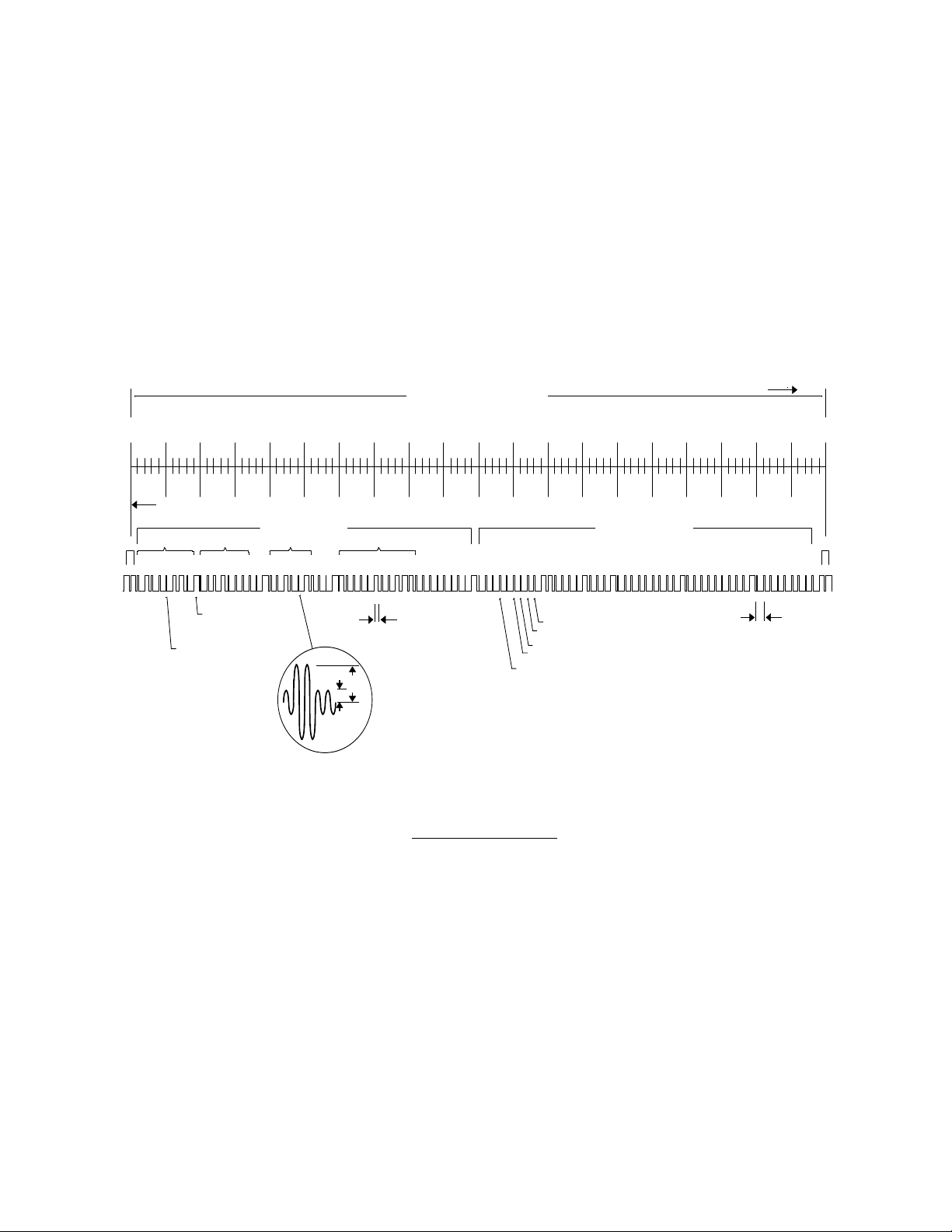
1/20/97
5PR
R
P
3
6
8P9P0
3X
X
C-3 EMBEDDED WORST-CASE TIME ERROR FLAGS
C-3.1 Five flags are encoded in the control function segment of the IRIG B code. The first flag
encoded at element P5+40ms is the LOCK indicator. It is a binary 1 when the unit has
lost contact with satellite signals. The second flag encoded at element P5+60ms is a
binary 1 when the worst-case time error exceeds threshold 1 as described in SECTION
III, "SERIAL I/O FUNCTION 05 -TIME QUALITY ENABLE/SETUP". Element P5+70ms
is a binary 1 when the worst-case time error exceeds threshold 2. Element P5+80ms
encodes a binary 1 when the error exceeds threshold 3 and P5+90ms when the error
exceeds threshold 4.
Figure C-1 (IRIG-B)
0
P0P
1 2 4 8 10 20 40 1 2 4 8 10 20 40 1 2 4 8 1 0 20 40 10 20 40 801 2 4 8
10 20 30 40 50 60 70 80 90 0
On-Ti me
BCD Time-of-Year
P2
0.1 s Position Identifier
Duration 8 ms
0.01 s Index Marker,
Duration 2 ms
TYPICAL MODULATED CA RRIER (1 000Hz)
P
TIME FRAME 1 SECOND
Time in 0. 01 s
P
Binar y One
5 ms Typical
P4
100 200
IRIG-B TIME CODE FORMAT
P
Time Qualit y 4
Time Quality 3
Ti me Qua li ty 2
Tim e Qua li ty 1
Lock Indicator
Control Functions
P7
TIME
P
10 ms Typical
NNTTSS--220011..MMAAN
N
CC--2
2
RReevv A
A
Page 75

APPENDIX D
DETAILED DRAWINGS / BILL OF MATERIALS
1/20/97
NNTTSS--220011..MMAAN
N
CC--1
1
RReevv A
A
 Loading...