

Page 1
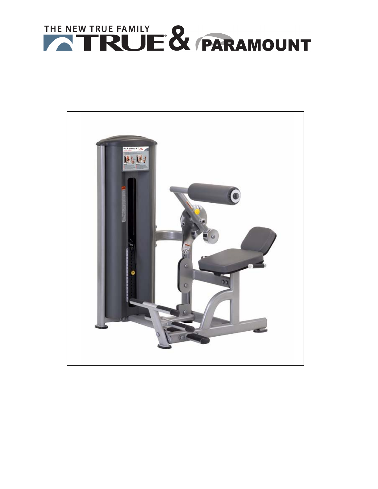
FS-57
A
BDOMINAL
A
SSEMBLY
/L
M
OWER
ANUAL
B
ACK
AM-FS57
010913
Page 2
A M
ESSAGE TO OUR CUSTOMERS
Thank you for purchasing products from the Paramount FS line. Because of the many unique
features included in these machines, this manual was created to provide you with information
on how to properly install and maintain your equipment. Proper maintenance will ensure that
your new equipment will last for years.
For your convenience, product questions can be answered by an Authorized Dealer or by
contacting the TRUE Customer Service Department at 1-800-883-8783 or Paramount Service
at 1-800-721-2121.
Office hours are Monday-Friday, 8:30 am - 5:00 pm CST
Or email us at [email protected] or [email protected]
Thank You for your patronage.
TRUE Fitness
865 Hoff Road
O'Fallon, MO 63366
IMPORTANT
!
SERIOUS INJURIES TO USERS, BYSTANDERS OR INSTALLERS CAN OCCUR IF THE
INSTRUCTIONS A
MINIMIZE THIS RISK, READ THE MANUAL BEFORE BEGINNING THE INSTALLATION TO
FAMILIARIZE YOURSELF WITH ITS CONTENTS AND THEN BE CERTAIN TO FOLLOW EACH
OF THE STEPS AND PRACTICES DESCRIBED. IN ADDITION, REVIEW THE GENERAL
MAINTENANCE MANUAL, FACILITY SAFETY SIGN AND OTHER DOCUMENTS THAT MAY
ACCOMPANY EACH MACHINE, FOR IMPORTANT SAFETY AND MAINTENANCE TIPS. THE
MANUAL HAS BEEN INCLUDED WITH YOUR MACHINE ORDER AND CAN ALSO BE
DOWNLOADED FROM OUR WEBSITE AT: http://www.truefitness.com
PLEASE RETAIN THIS MANUAL FOR FUTURE REFERENCE.
ND WARNINGS CONTAINED IN THIS MANUAL ARE NOT FOLLOWED. TO
2
Page 3

S
AFETY
...................................................................................................................... 4
G
ENERAL CARE AND MAINTENANCE
T
ABLE OF CONTENTS
........................................................................... 7
IMENSIONS AND WEIGHT
D
REPARATION
P
B
OX
1 C
OX
2 C
B
NSTALLATION
I
S
S
S
S
S
S
S
S
ACHINE LABELS
M
S
ERVICE
............................................................................................................. 9
ARTON CONTENTS
ARTON CONTENTS
& A
SSEMBLY
TEP
1: A
SSEMBLE THE MAIN FRAME
TEP
2: A
SSEMBLE THE ARM
TEP
3: A
SSEMBLE THE WEIGHT STACK
TEP
4: A
SSEMBLE THE CABLE
TEP
5: I
NSTALL THE FRONT SHROUD
TEP
6: I
NSTALL THE REAR SHROUD
TEP
7: I
NSTALL THE TOP CAP
TEP
8: I
NSTALL THE WEIGHT STACK LABEL
........................................................................................................ 23
..................................................................................................................... 24
........................................................................................... 8
............................................................................................ 10
............................................................................................ 11
...................................................................... 12
& P
ADS
..................................................................... 14
................................................................... 16
................................................................................ 17
...................................................................... 19
....................................................................... 20
................................................................................. 21
............................................................ 22
OLTING THE MACHINE TO THE FLOOR
B
ARRANTY
W
................................................................................................................. 26
............................................................................ 25
3
Page 4

S
AFETY
F
ACILITY AND USER SAFETY PRECAUTIONS
1. Review and understand all of the warning labels affixed to this machine and on the facility
safety sign.
2. Be certain that the machine operation is understood before it is used. Refer to th
nstructional Procedure Label affixed to the machin
i
. Make sure all users are properly trained on how to use this equipment. If this machine is
3
being used in a commercial setting, end users may not have access to this Owners Manual. It
is the responsibility of the facility to instruct users as to the proper usage of the equipment as
well as making them aware of potential hazards.
4. Use each machine only for the intended exercise. Do not allow anyone to invent exercises not
included on the Instructional Procedure Label or the Intended Use Label.
5.
6. This equipment meets industry safety standards for stability when used for the intended
7.
8. It is recommended that users receive a thorough medical exam before commencing an
ot modify the machine.
Do n
exercise. Do not allow straps, resistance bands or other means to be attached to
ramework of this machine to perform stretching or body weight exercises. This can result in
f
machine instability and lead to serious crushing injuries.
eep children away from this equipment. Adults should closely supervise use by teenagers.
K
exercise program. All medical issues should be reviewed to ensure that weight training will
not aggravate pre-existing medical conditions.
e.
e
the
9. If the machine appears damaged or inoperable, contact a facility staff member to place an
“OUT OF ORDER, DO NOT USE” sign on the machine until it is repaired. Only use Paramoun
upplied replacement components to service this machine.
s
10. Instruct users not to wear loose or dangling clothes or have headphone wires hanging
us
ing this equipment.
11.Do not attempt to free any jammed assemblies by yourself as this may cause injury.
12
. On P
late Loaded and Free Weight machines:
12a. Use of spotter(s). Instruct users to seek the advice of the facility staff as to the
appropriate use of spotters when lifting. More then one spotter may be required
depending upon the amount of weight being lifted.
12b. Instruct users to load weight plates evenly and carefully (one side and then the other)
to avoid tipping equipment and crushing injuries.
12c. If the machine is equipped with safety stops or catches, inspect them and verify their
proper operation before use and make sure they are securely in place before using or
exiting the machine. Be certain members are instructed on how to operate and adjust
all safety mechanisms.
4
when
t
Page 5
S
AFETY
12d. This equipment is designed for standard olympic size weight plates with a 50mm bore
(1.9”).
12e. Do not exceed the maximum weight capacity of the machine. Maximum plate size is
45 lbs. (25 kg.).
13. On Sel
13a. Do not allow users to perform any exercise by holding the end of the cable and/or th
13b. Do not high-pin or double-pin the weight stack. Do not allow the machine to be used if
13c. Do not allow the use of weight plates or dumbbells to be used as a means to add
I
NSTALLATION SAFETY PRECAUTIONS
1. Read this Installation Manual entirely before assembling this equipment.
2. Verify that there is adequate space surrounding this piece of equipment for safe access and
operation. Installation must meet ADA requirements for accessibility.
3. Install this piece of equipment on a solid level surface that does not deviate more then 1/
ver a 10’ distance (or as defined and required by local building and architectural codes.
o
ectorized and Cable equipped machines:
able end fitting. Use only appropriate handles or attachments properly connected to
c
the cable end.
the top plate or weight stack is pinned in a raised position. Use an assistant and
carefully return the machine to the proper position with the cap plate resting on the top
weight. Inspect the entire length of the cable to ensure that it is properly seated in all
of the pulley grooves.
additional weight to the weight stacks. Use only the Paramount adder weight system
specifically designed for the machine.
e
8”
4. Paramount strongly recommends that all equipment be anchored to the floor to prevent
movement and increase stability.
• Due to the wide variation of flooring on which the unit can be installed, contact
q
ualified contractor to determine an appropriate fastening system for your floor.
• Use 3/8” diameter hardware (10 mm) to anchor the machine. Anchors should have a
minimum pull out force of 220 lbs (110 kgs) for each position.
• When attaching the machine to the floor, if there is a gap between the machine f
nd the floor, do not use the anchor to remove the gap as this can cause th
a
achine frame to deform. Instead, place a shim between the bottom of the foot and
m
the floor, then tighten the anchor.
• Anchoring holes are provided on the feet of the frame. All anchoring locations must
be used when anchoring the equipment to the floor.
5.
DO NOT install any fitness equipment near a pool, hot tub or other damp locations. Corrosion
caused by installation in these locations can lead to premature failure of components.
e sure all hardware is tight before using this machine.
6. B
5
e
a
oot
Page 6
S
AFETY
M
AINTENANCE SAFETY PRECAUTIONS
1. Refer to Maintenance Schedule label on the machine as well as this manual for when to
perform maintenance.
2. C
heck the function of your machine DAILY by verifying the following:
• Inspect cables and end fittings for any signs of wear. Replace if worn, frayed or
damaged with original Paramount replacement components.
• Verify that all adjustments are possible and carried out with ease. Make sure tha
ach adjustment pin inserts completely into each position without binding.
e
• Verify that safety catches and stops are in proper working order and engaged.
• Verify that the exercise is performed smoothly, free of noise and/or bindin
•
If equipped with a weight stack, verify that the proper weight selector pin is in place.
3.
Check t
Replace any warning label at first sign of wear. Labels and the Facility Safety Sign may be
4.
obtained from Paramount free of charge.
B
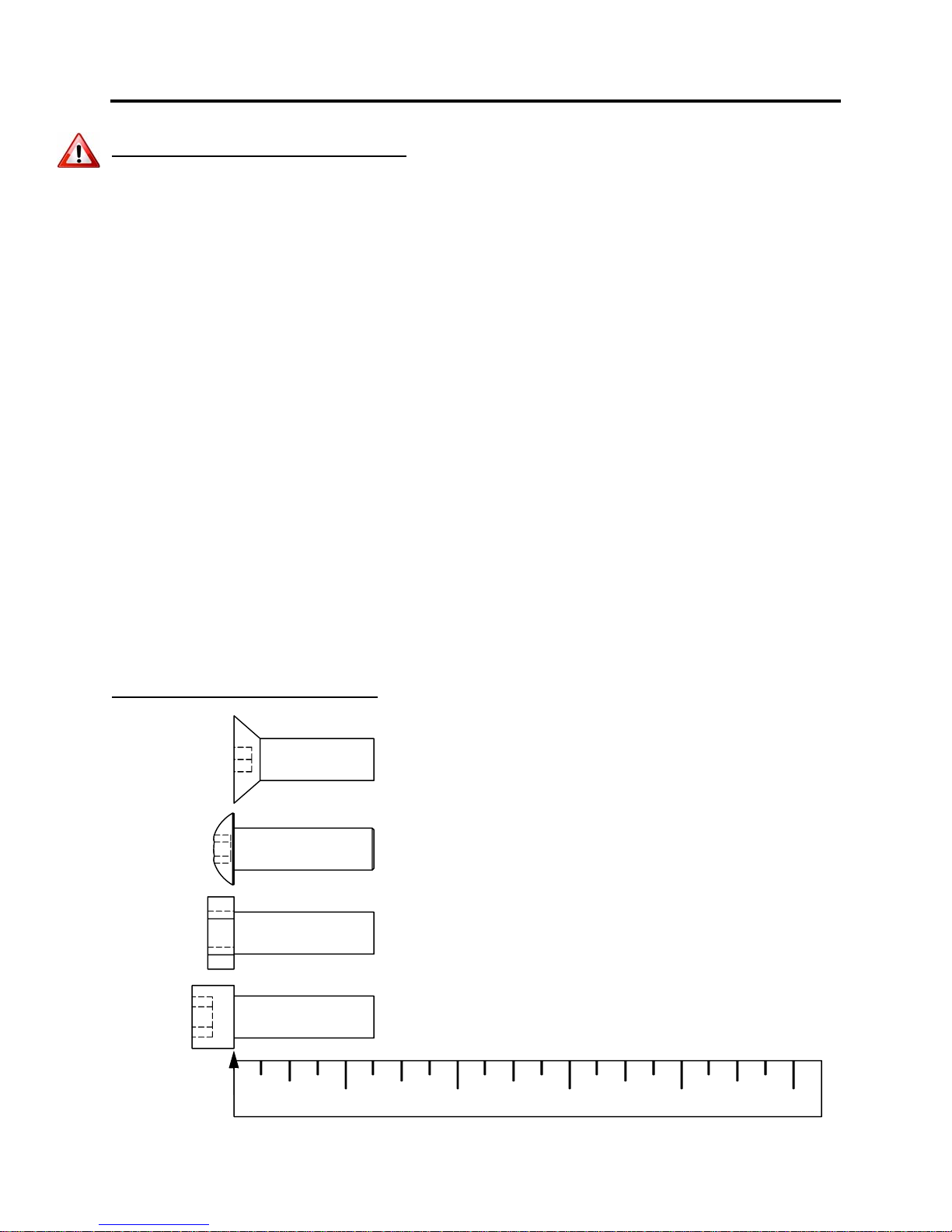
OLT LENGTH MEASURING GUIDE
he function of your machine WEEKLY by verifying the following:
• Nuts, Bolts, and Fasteners: Check tightness weekly. If any hardware has become
loose, retighten and/or use Loctite
rames and Lifting Arms: Inspect weekly for integrity and function. Replace any
• F
component at first signs of wear. Use only Paramount supplied components.
™
Threadlocker 242.
FLAT HEAD SCREW
t
g.
BUTTON HEAD SCREW
HEX HEAD SCREW
SOCKET HEAD SCREW
1
23
6
4
5
Page 7

G
ENERAL CARE AND
M
AINTENANCE
IMPORTANT
Preventative maintenance is crucial to maintaining the function and safety of this equipment. Your
facility must establish written guidelines for preventative maintenance and keep written or online
records of the maintenance performed on these products. As a minimum, the items presented in
the SAFETY section of this document and the items that follow here, should be included in your
maintenance program.
1. Cables: Inspect end fittings daily for wear. Inspect the entire length of the cable weekly
Replace cables at the first sign of wear and on an annual basis. If the cable tension has
been adjusted, be certain that the cable nut is tight.
2. Nuts, Bolts, and Fasteners: Check tightness weekly. If any hardware has become loose,
retighten and/or use Loctite
before using the machine.
3. Safety Catches: Inspect catches, stop rods and their associated fasteners weekly. Tighten
any loose hardware and replace any components at first signs of wear.
4. Frames: Wipe all machines down with a damp cloth and dry completely each day. This
includes painted parts, chrome parts and upholstered pads.
5. Painted and chrome plated parts: Use Simple Green or similar cleaner for light dirt and
grime. Use Turtle Wax Polishing Compound or a good car polish to remove heavier dirt
and grease as well as for polishing. DO NOT use solvents, lacquer thinner, acetone or
finger nail polish remover. For scuffs and marks that are not removed by the abov
methods use a soft scrub cleanser. Make sure all parts are dry upon completion.
6.
W
eight stack enclosures (shrouds): Wipe down with a damp cloth as needed.
7. Exercise instruction labels: Clean with soap and water as needed.
8. Guide rods: Wipe all dirt and dust from the guide rods before applying a light application
of Tri-Flow
the guide rods with the rag. DO NOT use oil lubricants such as WD-40. Caution: Tri-Flow
will stain carpet and clothing.
TM
or other teflon spray lubricant. Spray the Tri-FlowTM on a rag and then wipe
TM
brand Threadlocker 242. Be sure all hardware is tight
.
e
TM
9. Bronze bushings: Check monthly for signs of wear and replace as needed.
10. Linear Bearing Shafts: Wipe any accumulation of dust or other contaminants from the
shafts on a weekly basis. Apply a thin layer of a Teflon
Paramount recommends Magnalube
11. When replacing any component, use only Paramount supplied parts.
12. Please refer to the General Maintenance Manual (part number: AM-GMM) for othe
mportant safety and maintenance information.
i
13.
Be sure all hardware is tight before using the machine.
Retain these instructions for future reference.
If you have any questions, do not hesitate to contact your Paramount dealer or TRUE Fitness at
(800) 883-8783 or (800)721-2121 or [email protected] or
[email protected]
®
brand.
7
®
(PTFE) grease on a weekly basis.
r
Page 8
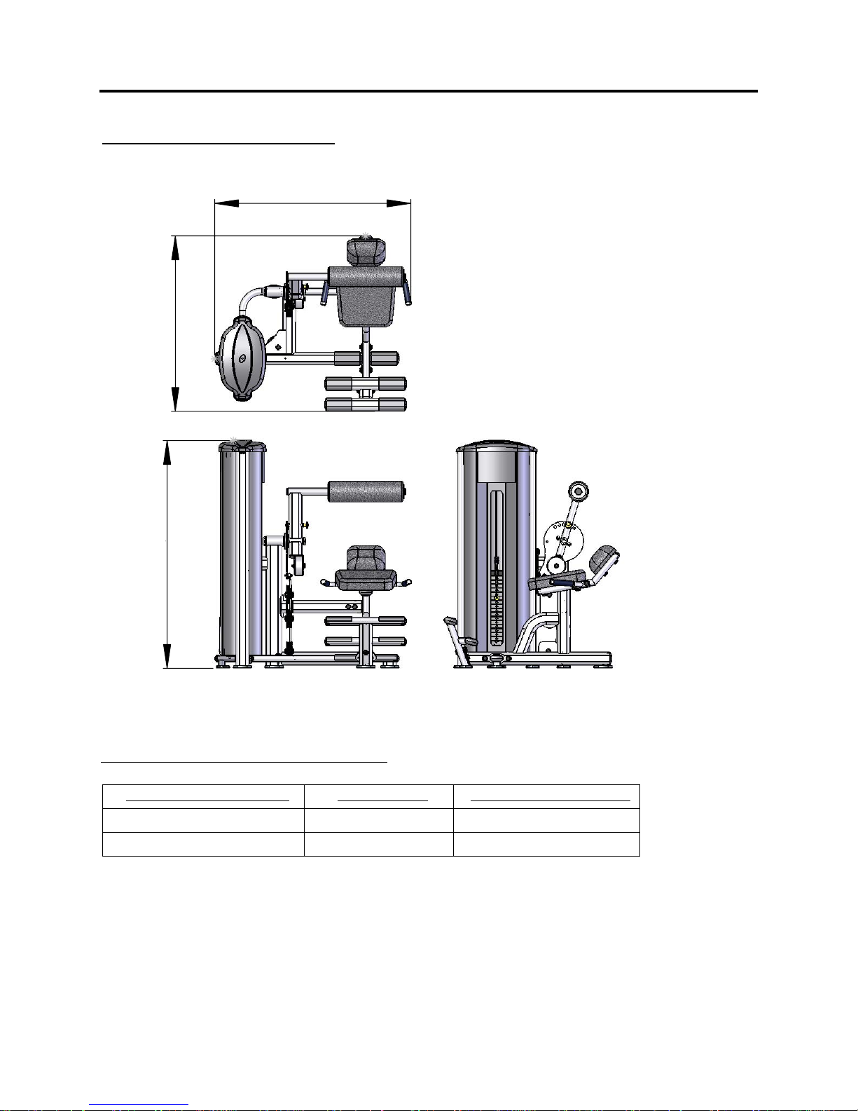
D
IMENSIONS AND
W
EIGHT
“IN USE” M
[1104]
43-1/2”
ACHINE DIMENSIONS
[1235]
48-3/4”
[1433]
56-1/2”
M
ACHINE WEIGHT AND FLOOR LOADING
W
EIGHT STACK CONFIGURATION
170 lbs. 374 LBS [170 KG] 44 LBS/FT2 [217 KG/M2]
250 lbs. 454 LBS [206 KG] 54 LBS/FT
Maximum user weight is 300 Lbs. (136 KG.)
M
ACHINE WEIGHT
A
PPROXIMATE FLOOR LOADING
2
[264 KG/M2]
8
Page 9
R
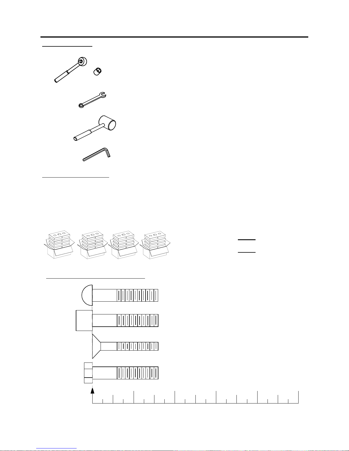
EQUIRED TOOLS
Ratchet Wrench and Socket:
9/16”
Wrenches: 9/16”, 3/4”
(or an adjustable crescent wrench).
Rubber mallet.
P
REPARATION
Weight Plate Cartons
Depending upon your order, this machine can be assembled with either a 170 lb. or 250
lb. weight stack. For a 170 lb. weight stack, (4) cartons of 10 lb. plates are required. For a
250 lb. weight stack, (4) cartons of 15 lb. plates are required.
See below for weight stack options/requirements:
Hardware Measurement Guide:
Allen wrenches:
BHCS - BUTTON HEAD CAP SCREW
(included with the machine)
10 LB. Weight Plate Box
Part Number: B1602
Comprised of
10 lb. Weight Plates
x
(4)
OR
15 LB. Weight Plate Box
Part Number: B1603
Comprised of
(4) x 15lb. Weight Plates
MEASURE BOLT
FROM HERE
SHCS - SOCKET HEAD CAP SCREW
FHCS - FLAT HEAD CAP SCREW
HHCS - HEX HEAD CAP SCREW
12345
9
Page 10
B
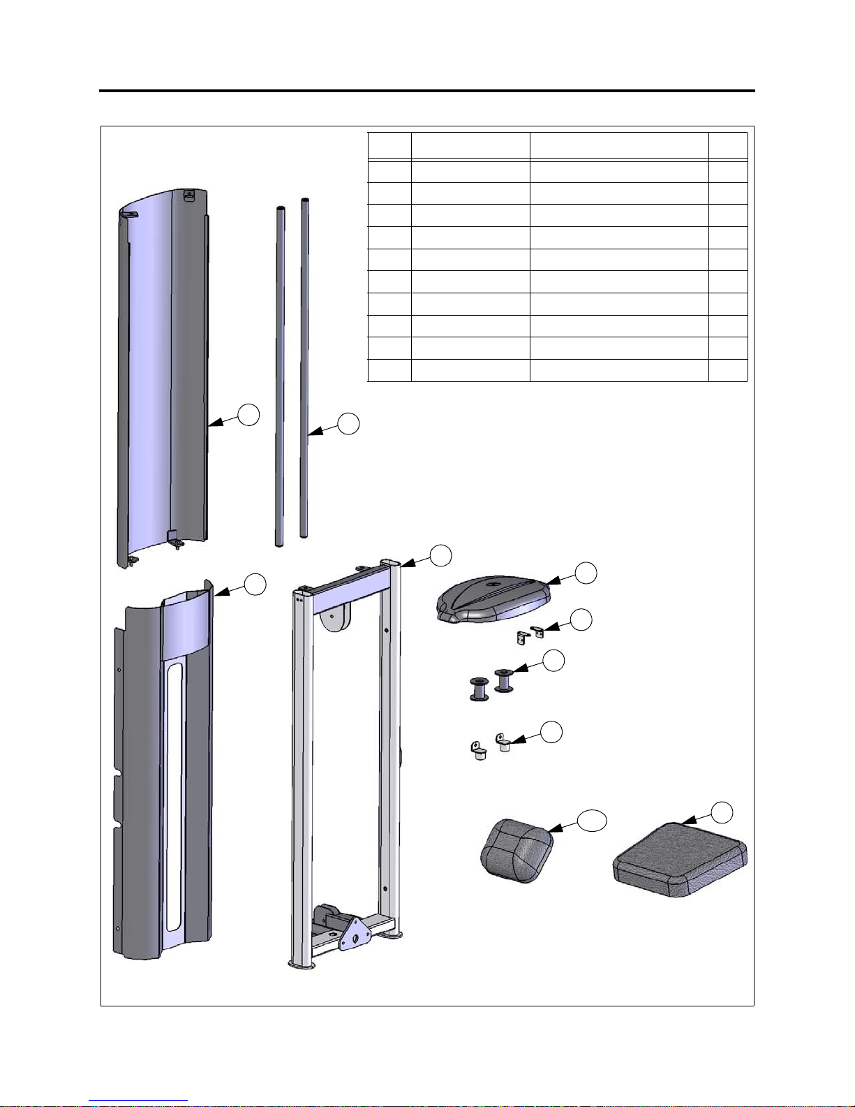
OX
1 C
ARTON CONTENTS
ITEMPART NUMBER
1 FS57-UPR-000X FRAME, UPRIGHT 1
2 FS57-SHD-100X SHROUD, FRONT 1
3 FS-SHD-150X SHROUD, REAR 1
4 FS-GRD-100X GUIDE ROD ASSEMBLY 2
5 FS-BKT-000 GUIDE ROD BRACKET 2
6 FS-WSB-000 WEIGHT STACK BASE 2
7 FS-CAP-000X TOP CAP 1
8 FS-BKT-001 BRACKET, TOP CAP 2
9 FS57-PAD-100X PAD, SEAT 1
10 FS57-PAD-000X PAD, BACK 1
3
4
D
ESCRIPTION
Q
TY
1
2
7
8
6
5
10
9
10
Page 11
B
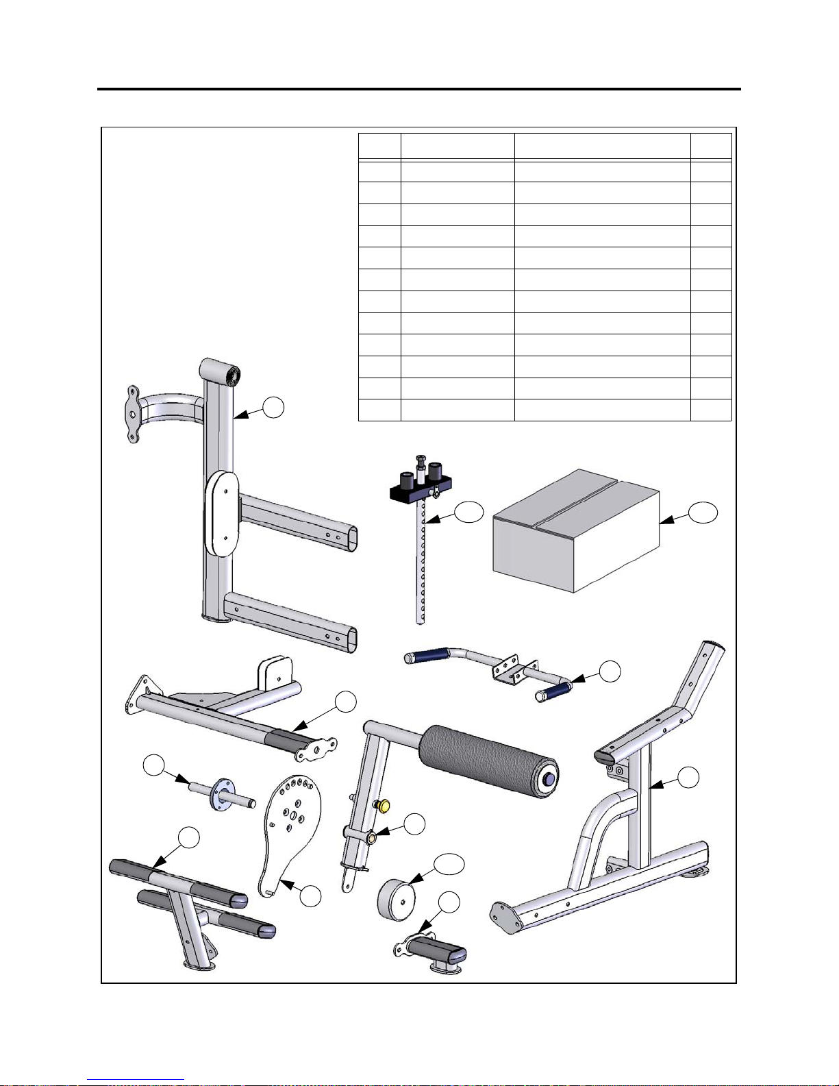
OX
2 C
ARTON
C
ONTENTS
ITEMPART NUMBER
1 FS57-ARM-000X ARM ASSEMBLY 1
2 FS57-MFR-000X FRAME, SEAT 1
3 FS57-MFR-300X FOOT REST, FRONT 1
4 FS57-MFR-100X PIVOT AXLE FRAME 1
5 FS57-MFR-200X BASE FRAME 1
6 FS57-MFR-400X FOOT REST, SIDE 1
7 FS57-MFR-500X HANDLE 1
8 FS57-ADJ-000X ADJUSTMENT DISC 1
9 FS57-AXL-000X AXLE 1
10 FS57-HWR-000X HARDWARE BOX 1
11 FS-SBR-000X TOP PLATE/SELECTOR BAR 1
4
12 FS-CWT-001 COUNTERWEIGHT, 120 X 55 1
11
D
ESCRIPTION
Q
10
TY
7
5
9
3
8
1
12
6
11
2
Page 12
S
TEP
1: A
SSEMBLE THE
M
AIN FRAME
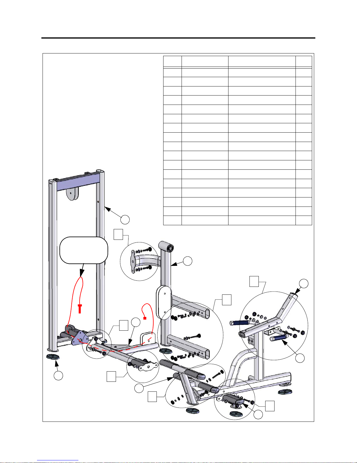
1. Before connecting the frame to the
up
right, route the cable through th
right and frame as shown.
up
2.
As
semble frame components as
shown.
3. Loosely assemble ALL hardware sho
this step
in
er aligning all component edges
4.Aft
and surfaces, tighten the hardware.
5.Install the rubber feet
.
1
e
ITEMPART NUMBER
1 FS57-UPR-000X UPRIGHT FRAME 1
2 FS57-MFR-000X SEAT FRAME 1
3 FS57-MFR-300X FOOT REST, FRONT 1
4 FS57-MFR-100X PIVOT AXLE FRAME 1
wn
5 FS57-MFR-200X BASE FRAME 1
6 FS57-MFR-400X FOOT REST, SIDE 1
7 FS57-MFR-500X HANDLE 1
8S 550 FOOT, MOLDED 7
9 C 955A BASE, BOLT COVER 22
10 C 955S COVER, BOLT 22
11 C 754C WASHER, FLAT, 3/8 22
12 C 749 WASHER, LOCK, 3/8 12
13 C 766A NUT, NYLOCK, JAM, 3/8 5
14 C 444 SCREW, HH, 3/8 X 3/4 2
15 C 445 SCREW, HH, 3/8 X 1 9
16 C 450 SCREW, HH, 3/8 X 2-1/2 4
17 C 455 SCREW, HH, 3/8 X 4 2
D
ESCRIPTION
Q
TY
ROUTE CABLE
THROUGH
FRAME FIRST
8
B
E
(
4
*
G
)
F
5
$
A
%
3
&
C
'
D
6
2
7
12
Page 13
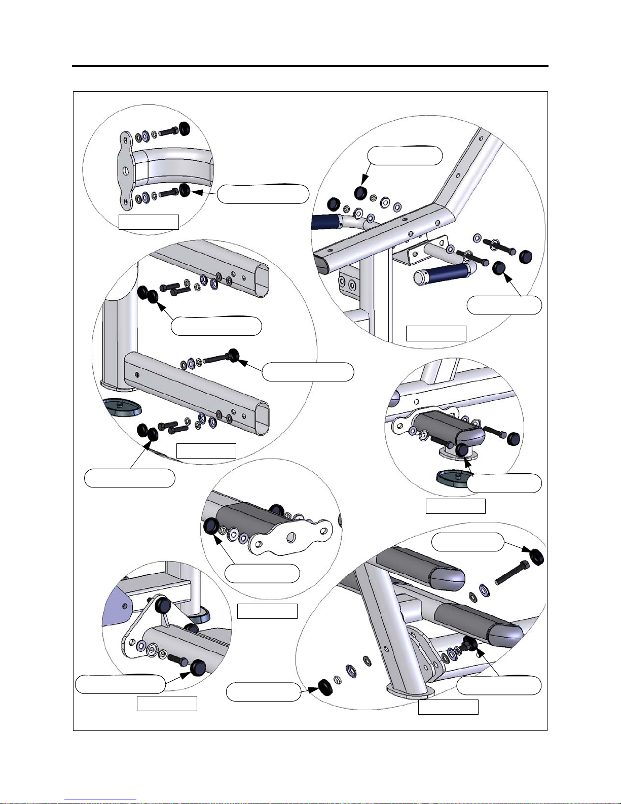
'(7$,/(
DETAIL E
S
TEP
1: A
10, 15, 12, 9, 11
SSEMBLE THE
10, 13, 9, 11
M
AIN FRAME
10, 17, 9, 11
10, 15, 12, 9, 11
10, 15, 12, 9, 11
'(7$,/)
DETAIL F
10, 13, 9, 11
'(7$,/%
DETAIL B
10, 16, 12, 9, 11
'(7$,/*
DETAIL G
'(7$,/'
DETAIL D
10, 16, 9, 11
10, 16, 9, 11
10, 15, 12, 9, 11
'(7$,/$
DETAIL A
10, 13, 9, 11
13
10, 14, 12, 9, 11
'(7$,/&
DETAIL C
Page 14
S
TEP
2: A
SSEMBLE THE ARM
& P
ADS
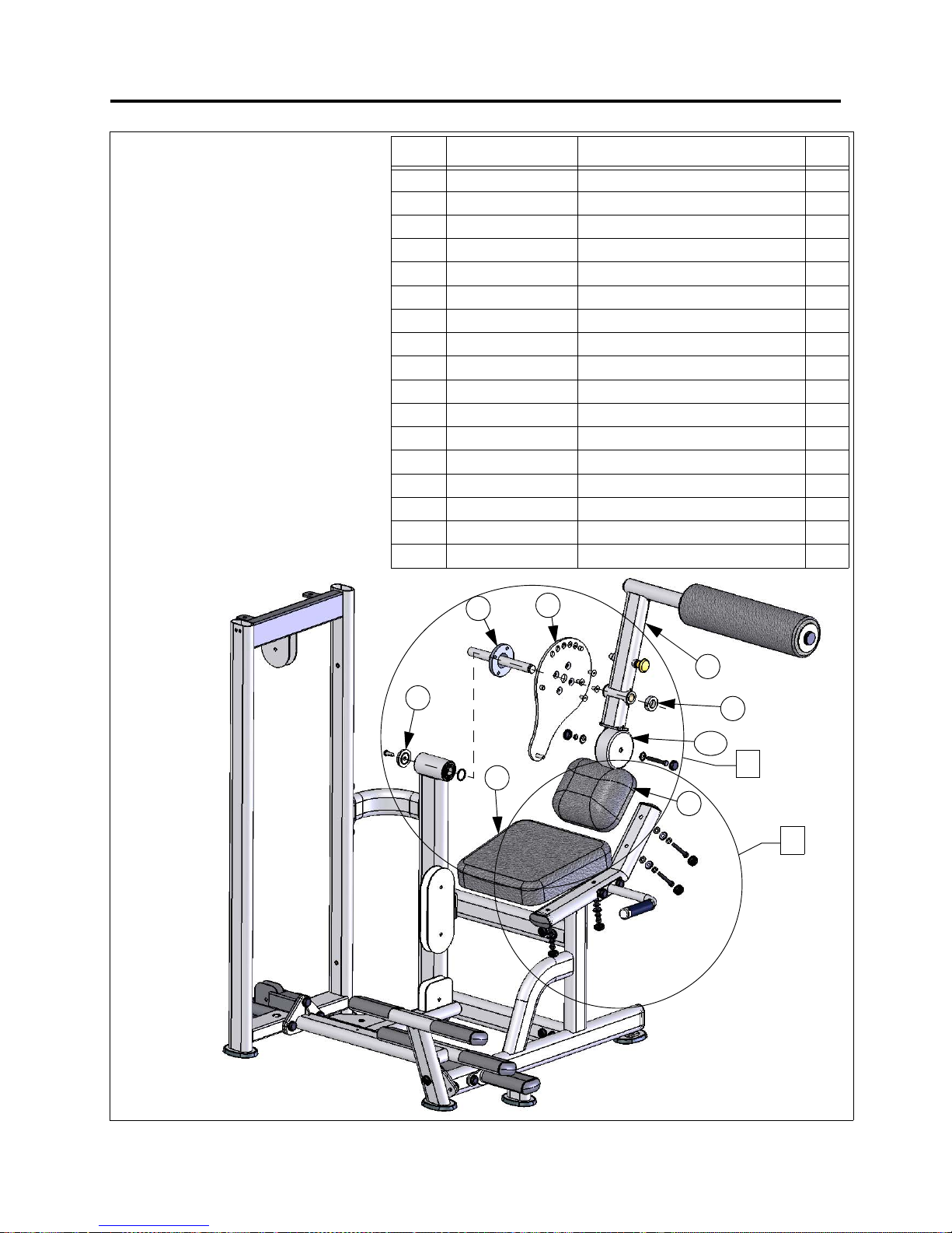
1. Assemble the Adjustment Disc to
the Axle with (4) Flat Head
Screws. Use blue Loctite #242 on
the threads of the screws.
sert the axle into the frame
In
2.
and install the Axle Cap.
ide the Arm Assembly onto th
3. Sl
a
xle and install the retainin
co
llar.
4.Make sure arm can adjust easily
and verify that the pop pin full
serts into each adjustment
in
hole.
semble pads as shown.
5. As
6.Assemble the counter weight to
the arm.
g
y
ITEMPART NUMBER
1 FS57-ARM-000X ARM ASSEMBLY 1
2 FS57-ADJ-000X ADJUSTMENT DISC 1
3 FS57-AXL-000X AXLE 1
4 FS-CLR-001 COLLAR, 32mm 1
5 FS-CAP-002 CAP, AXLE, BEARING SPACER 1
6 FS57-PAD-100X PAD, SEAT 1
e
7 FS57-PAD-000X PAD, BACK 1
8 C 657 SCREW, FLAT HEAD, 3/8 X 3/4 4
9 C 678 SCREW, BUTTON HEAD, 3/8 X 1 1
10 C 955A BASE, BOLT COVER 6
11 C 955S COVER, BOLT, SILVER 6
12 C 749 WASHER, LOCK, 3/8 4
13 C 754C WASHER, FLAT, 3/8 4
14 C 451 SCREW, HEX HEAD, 3/8 X 2-3/4 5
15 C 766A NUT, NYLOCK, JAM, 3/8 1
16 FS-CWT-001 COUNTERWEIGHT, 120 X 55 1
17 FS-SPC-001 SPACER, BEARING 1
D
ESCRIPTION
Q
TY
3
5
6
2
1
4
16
L
/
7
K
.
14
Page 15
S
TEP
2: A
SSEMBLE THE ARM
& P
ADS
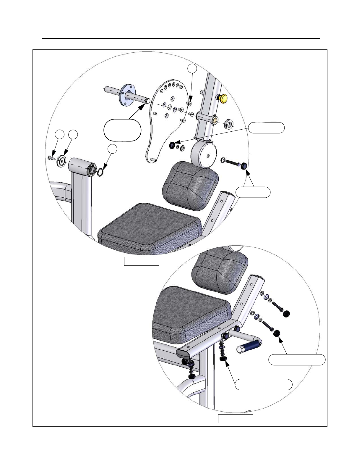
USE BLUE LOCTITE
9
5
NOTE:
GROOVE
LOCATION
17
USE BLUE LOCTITE
8
11, 15, 10
11, 14, 10
'(7$,//
DETAIL L
11, 14, 12, 10, 13
'(7$,/.
DETAIL K
11, 14, 12, 10, 13
15
Page 16
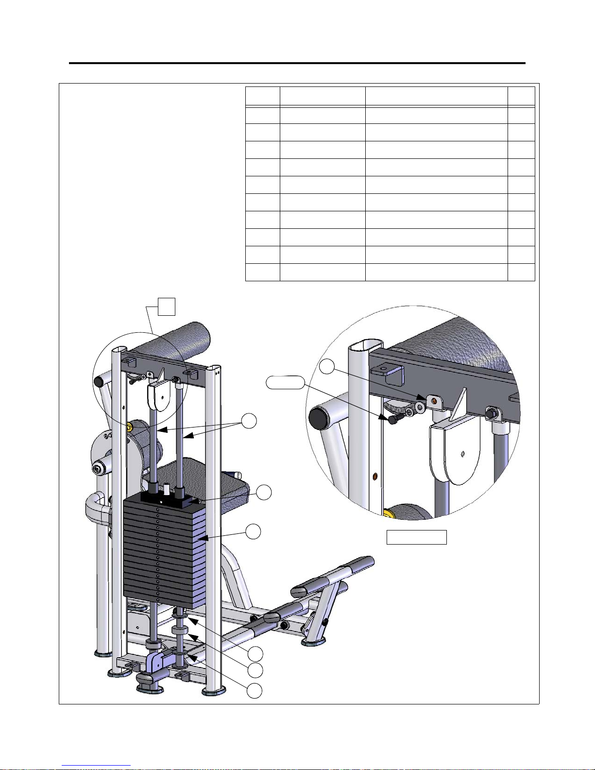
S
TEP
3: A
SSEMBLE THE
W
EIGHT STACK
1. Install the Weight Stack Supports,
Weight Stack Bumpers, Weight
Stack Washers, and Guide Rods.
2.
Install 16 weight plates accordin
o your order (10 or 15 lb. plates).
t
ssemble Top Plate/Selector Bar.
3. A
4.
A
ttach guide rod to top frame with
Guide Rod Bracket as shown.
0
M
ITEMPART NUMBER
1 FS-WSB-000 WEIGHT STACK BASE 2
g
2 C 757A WASHER, WEIGHT STACK 2
3 FS-BMP-001 BUMPER, WEIGHT STACK 2
4 WGT. PLATE 10# OR 15# WEIGHT PLATE 16
5 FS-SBR-000X TOP PLATE/SELECTOR BAR 1
6 FS-GRD-100X GUIDE ROD ASSEMBLY 2
7 FS-BKT-000 GUIDE ROD BRACKET 2
8 C 445 SCREW, HEX HEAD, 3/8 X 1 2
9C 749 WASHER, LOCK, 3/8 2
10 C 754C WASHER, FLAT, 3/8 2
7
8, 9, 10
D
ESCRIPTION
Q
TY
6
5
4
2
3
1
'(7$,/0
DETAIL M
16
Page 17
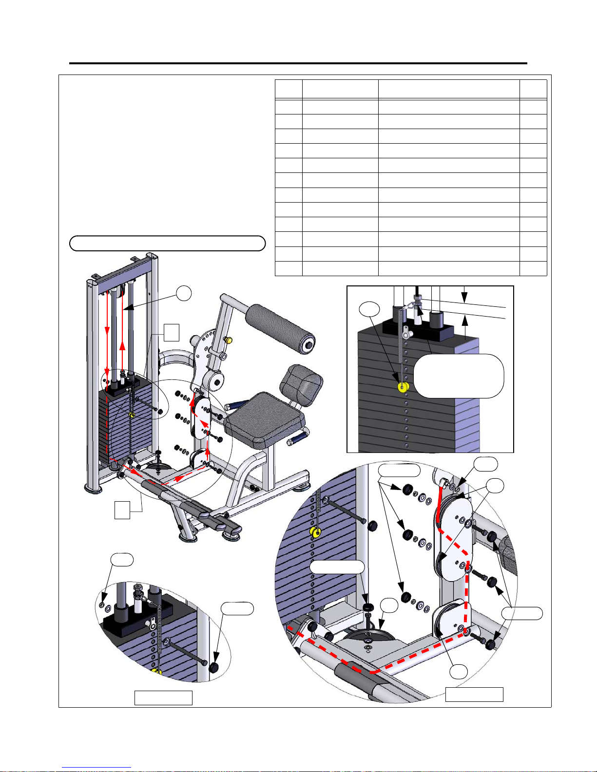
S
TEP
4: A
SSEMBLE THE CABLE
1. Starting at the top plate, assemble the
c
able as shown, installing pulleys an
rdware as you go.
ha
2. Tighten the cable bolt to the remove sl
the cabl
from
nsure that the adjustment bolt is inserted
3.E
into the selector bar according to the
minimum dimension specification shown.
4. Install the 5-1/2” long bolt in the first
weight plate as shown in Detail Q.
CABLE ROUTING CONTINUED ON NEXT PAGE.
e.
4
1
Q
d
ack
ITEMPART NUMBER
1 FS57-CBL-100X CABLE, AB/BACK 1
2 C 955A BASE, BOLT COVER 8
3 C 955S COVER, BOLT, SILVER 7
4 C 955 COVER, BOLT, BLACK 1
5 C 754C WASHER, FLAT, 3/8 13
6C 749 WASHER, LOCK, 3/8 1
7 C 766A NUT, NYLOCK, JAM, 3/8 7
8 C 448 SCREW, HEX HEAD, 3/8 X 1-3/4 6
9 C 461 SCREW, HEX HEAD, 3/8 X 5-1/2 1
10 B 900 PULLEY, 4-1/2” DIAMETER 5
11 B 898 PULLEY, 6” DIAMETER 1
12 FS-SPN-000X SELECTOR PIN 1
12
D
ESCRIPTION
M
A
1
”
(
2
INSTALL SELECTOR
PIN RING AROUND
CABLE BOLT
AS SHOWN
X
5
m
m
)
Q
TY
N
1
7, 5
DETAIL Q
'(7$,/4
4, 9, 2
17
3, 8, 6, 2, 5
3, 7, 2, 5
11
7, 5
10
10
DETAIL N
'(7$,/1
3, 8, 2, 5
Page 18
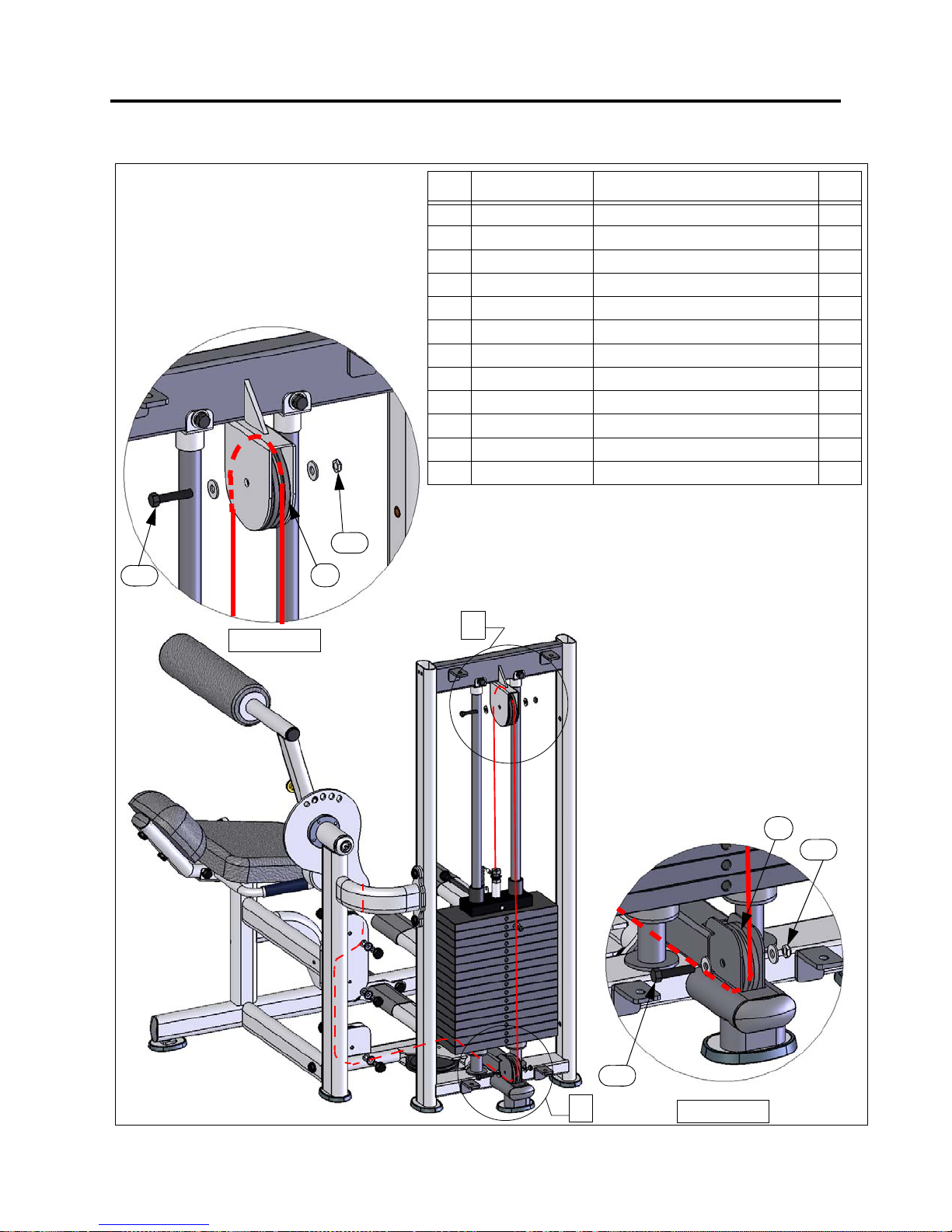
S
TEP
4: A
SSEMBLE THE CABLE
8, 5
DETAIL P
'(7$,/3
10
7, 5
ITEMPART NUMBER
1 FS57-CBL-100X CABLE, AB/BACK 1
2 C 955A BASE, BOLT COVER 8
3 C 955S COVER, BOLT, SILVER 7
4 C 955 COVER, BOLT, BLACK 1
5 C 754C WASHER, FLAT, 3/8 13
6C 749 WASHER, LOCK, 3/8 1
7 C 766A NUT, NYLOCK, JAM, 3/8 7
8 C 448 SCREW, HEX HEAD, 3/8 X 1-3/4 6
9 C 461 SCREW, HEX HEAD, 3/8 X 5-1/2 1
10 B 900 PULLEY, 4-1/2” DIAMETER 5
11 B 898 PULLEY, 6” DIAMETER 1
12 FS-SPN-000X SELECTOR PIN 1
P
3
D
ESCRIPTION
Q
TY
18
O
2
8, 5
'(7$,/2
DETAIL O
10
7, 5
Page 19
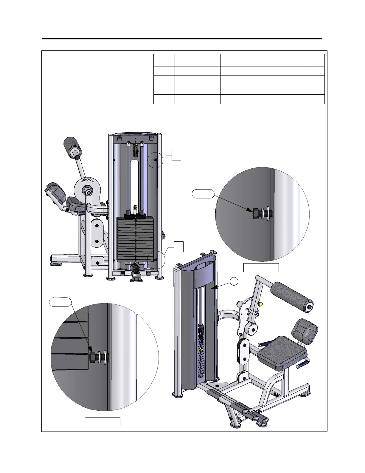
S
TEP
5: I
NSTALL THE FRONT SHROUD
1. Assemble the front shroud as
shown.
2. Oper
ate the machine and make
sure that the weight stack clears
the shroud. Adjust the position
re
quired.
if
ITEMPART NUMBER
1 FS57-SHD-100X SHROUD, FRONT 1
2 C 754C WASHER, FLAT, 3/8 4
3C 749 WASHER, LOCK, 3/8 4
4 C 445 SCREW, HEX HEAD, 3/8 X 1 4
<
Y
4, 3, 2
D
ESCRIPTION
Q
TY
4, 3, 2
;
X
DETAIL Y
'(7$,/<
1
'(7$,/;
DETAIL X
19
Page 20
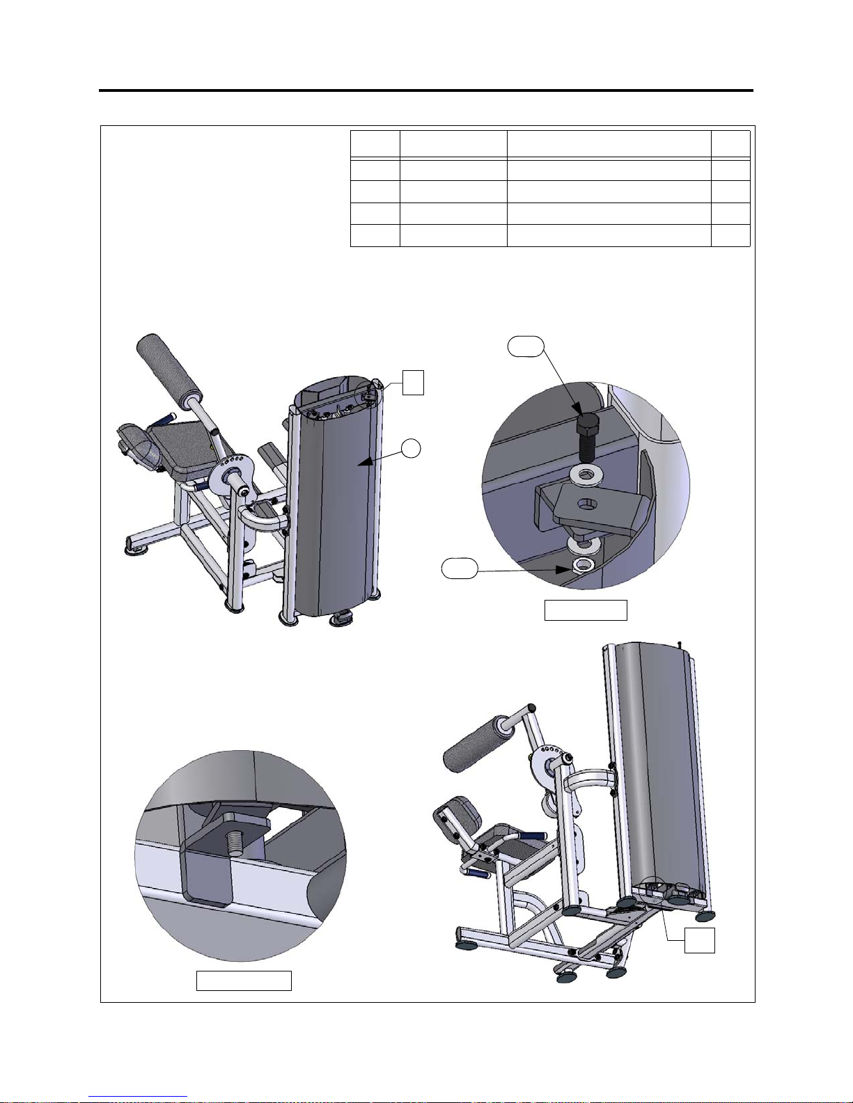
S
TEP
6: I
NSTALL THE REAR SHROUD
1. Assemble the rear shroud as
shown.
2. Opera
te the machine and make
sure that the weight stack cl
he shroud. Adjust the position if
t
required.
ears
ITEMPART NUMBERDESCRIPTION
1 FS-SHD-150X SHROUD, REAR 1
2 C 754C WASHER, FLAT, 3/8 4
3C 766A NUT, NYLOCK, JAM, 3/8 2
4 C 444 SCREW, HEX HEAD, 3/8 X 3/4 2
4, 2
=
Z
1
Q
TY
3, 2
'(7$,/=
DETAIL Z
=
Z1
'(7$,/=
DETAIL Z1
20
Page 21
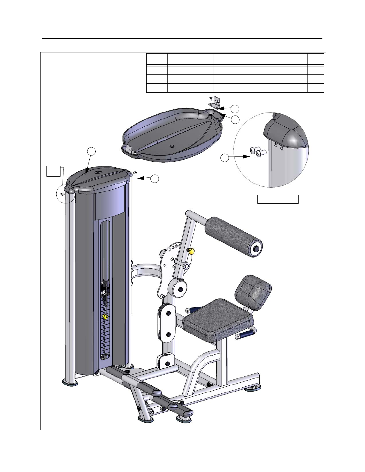
S
TEP
7: I
NSTALL THE TOP CAP
1. Assemble the bracket to the top
ca
p as shown.
2.Assemble the top cap to the
upright frame.
1
$%
AB
ITEMPART NUMBER
1 FS-CAP-000X TOP CAP 1
2 C 675D SCREW, BUTTON HEAD, 1/4 X 1/2 8
3 FS-BKT-001 BRACKET, TOP CAP 2
2
D
ESCRIPTION
2
3
2
'(7$,/$%
DETAIL AB
Q
TY
21
Page 22
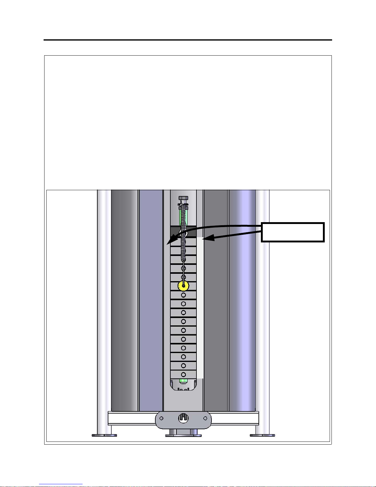
S
TEP
8: I
NSTALL THE
W
EIGHT STACK LABEL
1. Select the appropriate weight stack label(s) according to your order. You can install pound
la
bels, kilogram labels, or both.
2. I
f you ordered a 170 lb. weight stack, use labels:
LBL-WSE-01170 (for pounds)
LBL-WSM-01170 (for kilograms).
you ordered a 250 lb. weight stack, use labels:
If
3.
LBL-WSE-01250 (for pounds)
LBL-WSM-01250 (for kilograms).
4.Remove the backing from the label to expose the adhesive. Carefully locate the label on th
s
hroud so that it is centered between the edge and the bend. Line up the numbers with thei
c
orresponding weight plate. Once the correct position is attained and the label is a uniform
distance from the edge, press firmly along the entire length of the label.
TE: Adhesive takes 24 hours to fully set.
NO
5.
INSTALL LABEL HERE
OR HERE
20
30
40
50
60
70
80
90
100
110
120
130
140
150
160
170
e
r
22
Page 23
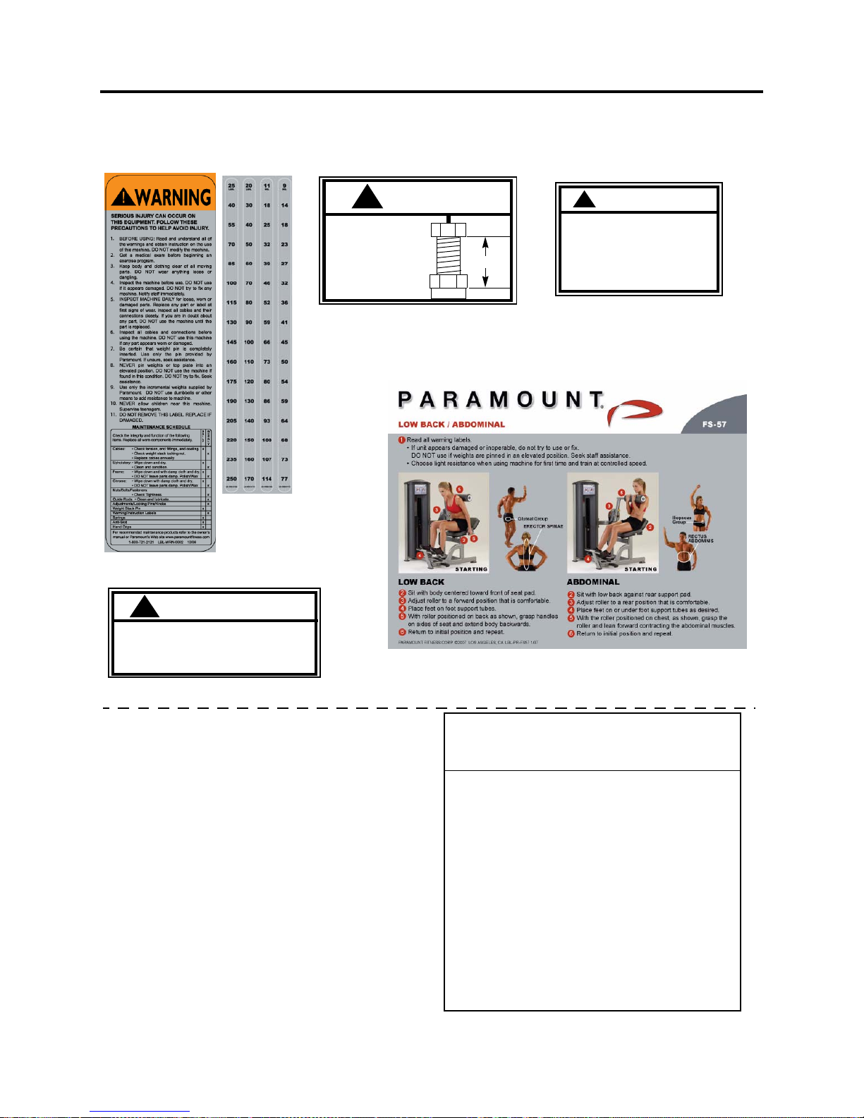
M
ACHINE LABELS
The following are the Warning labels required for this FS machine. If any of these
labels are missing or become damaged, we will replace them free of charge.
Note: these labels are not to scale.
LBL-WSE-01170 (170 LB)
LBL-WSE-01250 (250 LB)
LBL-WSM-01170 (77 KG)
LBL-WSM-01250 (114 KG)
LBL-WRN-0002
WARNING
!
SERIOUS INJURY CAN OCCUR ON
THIS EQUIPM EN T IF TH E PIN IS NOT
COMPLETELY INSERTED BEFORE USE.
ASTM F1749
P/N B2065
B2065
WARNING
!
MAXIMUM
Height Under Nut
to Bolt Head.
MAKE SURE
locking nut is tight.
B2141C
B2141C
MAX
1”
SERIOUS INJURY CAN OCCUR
ON THIS EQUIPMENT IF THE
CABLES AND THEIR ATTACH-
MENT COMPONENTS ARE NOT
INSPECTED OFTEN. REPLACE
AT FIRST SIGNS OF WEAR.
LBL-PR-FS57
!
W ARNING
B2051
P/N B2051
If this machine is to be installed in a
public use facility, ASTM F1749
requirements specify that the facility
sign shown to the right is to be installed
in plain view.
If you did not receive the facility sign
with your order, you can obtain one free
of charge by calling 1-800-883-8783 or
1-800-721-2121.
BE ALERT!
THE FITNESS EQUIPMENT IN THIS FACILITY
PRESENTS HAZARDS WHICH, IF NOT AVOIDED,
COULD CAUSE SERIOUS INJURY OR DEATH.
PRIOR TO USING THE EQUIPMENT, READ THE WARNING LABELS
AND INSTRUCTION PLACARDS AFFIXED TO EACH MACHINE.
IF YOU ARE UNSURE ON HOW TO USE A MACHINE, SEEK THE
ASSISTANCE OF OUR FLOOR PERSONNEL. WE WILL BE HAPPY
TO INSTRUCT YOU ON HOW TO USE THE EQUIPMENT PROPERLY.
IMMEDIATELY REPORT ANY PIECE OF EQUIPMENT THAT IS NOT
FUNCTIONING PROPERLY TO OUR FLOOR PERSONNEL SO THAT
IT MAY BE EVALUATED AND SERVICED PROMPTLY.
DO NOT ATTEMPT TO USE OR FIX ANY PIECE OF EQUIPMENT
THAT IS NOT FUNCTIONING PROPERLY
ASTM F1749-96
23
Page 24
S
ERVICE
H
OW TO OBTAIN SERVICE
For warranty service, contact an Authorized Paramount Dealer or a TRUE Fitness
Customer Service representative at 1-800-883-8783 or 1-800-721-2121. You can also
email us at [email protected] or [email protected]
Before you call, please have the following information ready:
• Model Number: FS-57
• Serial Number: ________________________
• Date of Installation: ____________________
• A brief description of the problem
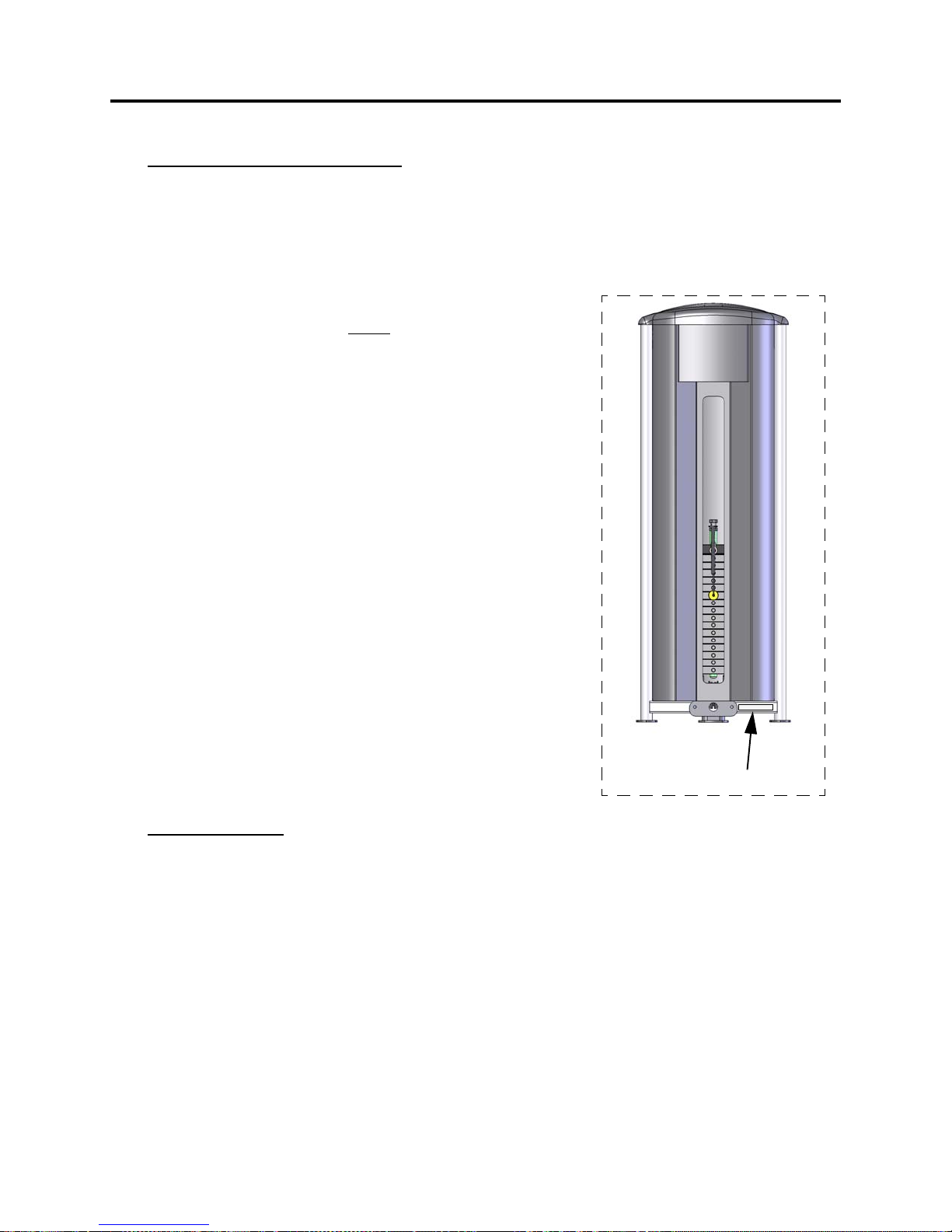
The serial number is located on the front of the upright
frame at the bottom as shown.
F
INAL CHECK
1. If you haven’t already done so, lubricate the guide rods and seat adjustment tubes with
a teflon spray lubricant. Paramount recommends using TriFlow
2.Verify that all adjustments can be made into each position and that the adjustment pin
is fully engaged.
3.Place the selector pin into the holder on the cap plate. Perform the exercise slowly
V
erify that the cable moves freely, without any binding. Repeat this procedure for each
exercise on the machine.
4. V
erify that the selector pin can be inserted into each weight plate.
24
Serial Number
TM
brand.
.
Page 25
FS B
The machines in this product line were designed and tested to meet the ASTM (American) and EN
(European) safety standards for stability (without floor anchors) when the machine is used for it’s
intended purpose as designated by the manufacturer.
However, Paramount strongly recommends that all equipment be anchored to the floor to prevent
movement and increase stability.
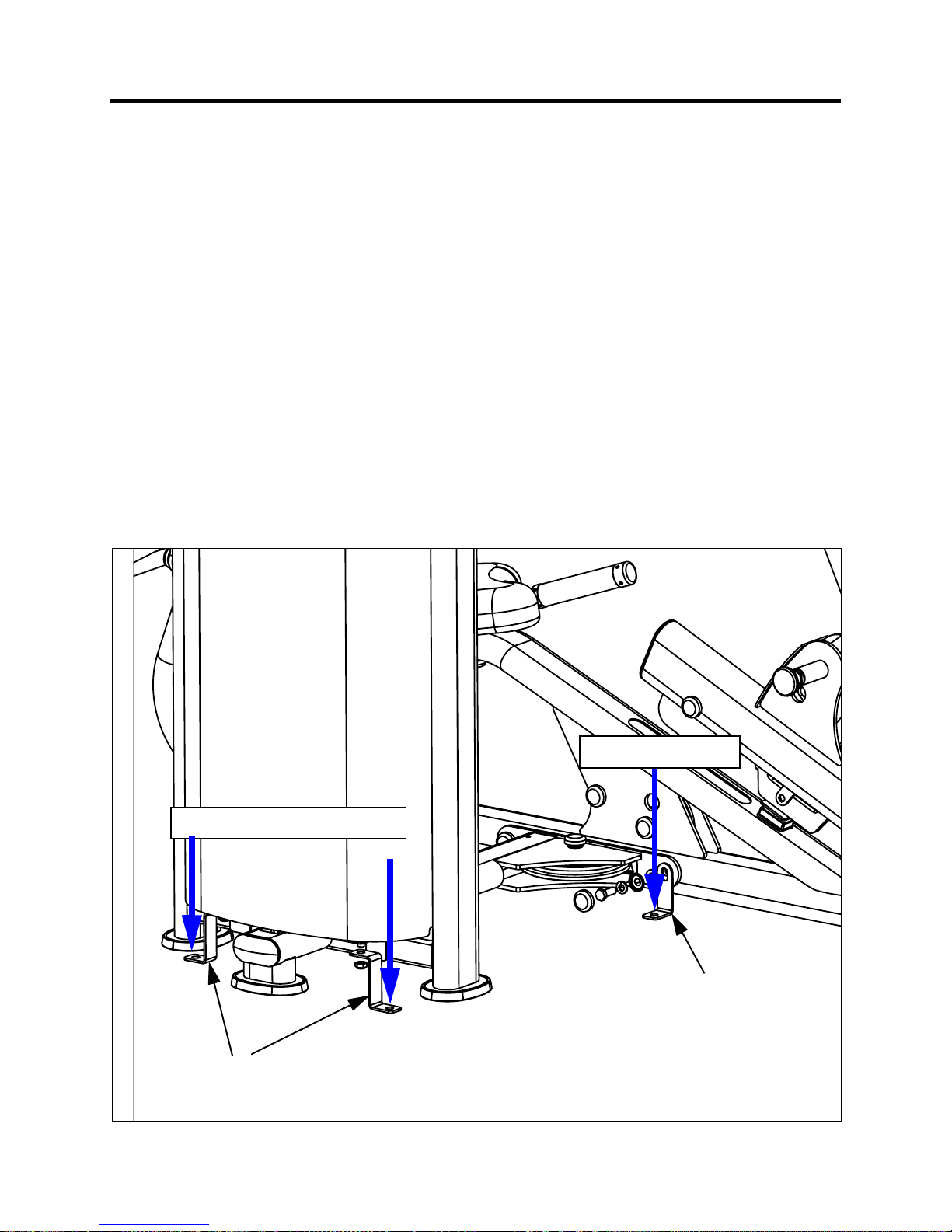
OLT DOWN INSTRUCTIONS
• You will need to order an anchoring kit for each machine. This kit will include brackets and
instructions for securing the brackets to the machines. Note: the kit does not include th
f
loor anchor bolts. Order part number: FS-BLTDN-000X, 1 kit per FS machine.
e
• Due to the wide variation of flooring on which the unit can be installed, contact a qualifie
c
ontractor to determine an appropriate fastening system for your floor.
• Use 3/8” diameter hardware (10 mm) to anchor the machine. Anchors should have a
minimum pull out force of 220 lbs (110 kgs) for each position.
• When attaching the machine to the floor, if there is a gap between the machine foot (or
bracket) and the floor, do not use the anchor to remove the gap as this can cause the
machine frame to deform. Instead, place a shim between the bottom of the foot and th
loor, then tighten the anchor.
f
Floor Anchor Point
d
e
Floor Anchor Point
Upright hold down brackets with hardware
(included in kit, qty 2)
Main frame hold down bracket
(included in kit, qty 1)
Re-uses existing machine
hardware. Refer to kit instructions
for details.
25
Page 26

P
ARAMOUNT LIMITED
READ PARAMOUNT’S WARRANTY SET FORTH BELOW PRIOR TO USING PARAMOUNT PRODUCTS. BY INITIAL USE OF PARAMOUNT
PRODUCT YOU ARE CONSENTING TO BE BOUND BY THE FOLLOWING WARRANTY TERMS AND CONDITIONS. THE WARRANTY
PERIODS COMMENCE ON THE INVOICE DATE OF THE ORIGINAL PURCHASE. LABOR COVERED DURING WARRANTY PERIODS
REQUIRES PRIOR AUTHORIZATION OF PARAMOUNT. PARAMOUNT WARRANTS TO THE ORIGINAL BUYER OF ALL NEW EQUIPMENT
PURCHASED FROM A PARAMOUNT AUTHORIZED DEALER OR FROM A PARAMOUNT AUTHORIZED MANUFACTURING CONTRACTOR
THAT THESE PRODUCTS WILL BE FREE FROM DEFECTS IN MATERIAL AND WORKMANSHIP UNDER NORMAL USE AND SERVICE FOR
THE FOLLOWING PERIODS AND IN THE FOLLOWING RESPECTS:
STRENGTH PRODUCTS
• TEN YEAR WARRANTY COMMERCIAL PRODUCTS – Frame Components and Welds excluding coatings
• FIVE YEAR WARRANTY - Bronze Bushings, Sealed Rotating Bearings, Pulleys, Weight plates and Guide Rods excluding coatings
• ONE YEAR WARRANTY - Cables, Linear Bearings and Shafts and all other components not mentioned elsewhere in this
warranty
• 90-DAY WARRANTY - Normal wear parts including but not limited to labels, upholstered pads and grips
• ONE YEAR WARRANTY – Labo
HIPPING MODE OF PARTS REPLACED UNDER WARRANTY TO BE DETERMINED BY PARAMOUNT. PARTS REPLACED UNDER
THE S
WARRANTY CARRY THE REMAINING ORIGINAL WARRANTY PERIOD OR 90 DAYS, WHICHEVER IS LONGER.
THIS LIMITED WARRANTY DOES NOT COVER AND NO WARRANTY IS GIVEN WITH RESPECT TO:
• Products not manufactured by Paramount or by an Authorized Paramount Manufacturing Contractor.
• Products which are altered without the express written consent of Paramount.
• Products purchased other than directly from Paramount or through a Paramount Authorized Dealer.
• Defective paint, chrome and other coatings caused by environmental conditions including but not limited to climate conditions,
cleaning materials and moisture or humidity coming from HVAC system
•
All parts including but not limited to frames with cosmetic damage. Such damage includes but is not limited to scratches an
den
ts caused after the initial installation
•
Products not maintained in compliance with Paramount’s specifications as shown in the owners’ manual and on prod
la
bels.
• Products with a missing, unreadable or altered serial tag.
• Labor for components beyond their warranty coverage.
• On site service calls to solve installation errors or to provide technical training on the proper use and servicing of the equipment.
r
.
W
ARRANTY
s.
d
uct
THIS WARRANTY APPLIES UNDER THE FOLLOWING CONDITIONS.
• These products have not been subjected to misuse, abuse, modifications not authorized by Paramount or any damage caus
by improper handling, natural disasters, acts of God or servicing by non-Authorized Dealers. This includes but is not limited to
the relocation of the product and the application of cleaning materials or lubricants not specified by Paramount.
• These products remain in possession of the original purchaser.
• Warranty claims are made within the warranty periods previously shown and that such claims occur within 30-days after the
date of discovery.
• Labor coverage applies only within the United States and Canada
Warranties for parts and labor may vary outside the United States. Contact the Paramount Dealer within your geographic area
•
for warranty terms.
THE OBLIGATION OF PARAMOUNT UNDER THIS WARRANTY IS LIMITED TO REPAIRING OR REPLACING WARRANTED DEFECTIVE
PARTS, AS PARAMOUNT MAY ELECT, AT PARAMOUNT'S PLANT IN LOS ANGELES, CALIFORNIA. PURCHASER IS RESPONSIBLE FOR
ALL TRANSPORTATION AND INSURANCE COSTS ON RETURNED OR REPLACED EQUIPMENT TO AND FROM PARAMOUNT'S PLANT IN
LOS ANGELES. ANY IMPLIED WARRANTY, INCLUDING BUT NOT LIMITED TO THE IMPLIED WARRANTY OF FITNESS FOR A
PARTICULAR PURPOSE AND THE IMPLIED WARRANTY OF MERCHANTABILITY, IS LIMITED TO ONE-YEAR DURATION FROM THE DATE
OF DELIVERY TO THE ORIGINAL PURCHASER. SOME STATES DO NOT ALLOW LIMITATIONS ON HOW LONG AN IMPLIED WARRANTY
LASTS, SO THE ABOVE LIMITATION MAY NOT APPLY TO YOU. THE REMEDY OF REPAIR AND REPLACEMENT IS THE EXCLUSIVE AND
SOLE REMEDY OF THE PURCHASER.
PARAMOUNT SHALL NOT BE LIABLE FOR ANY SPECIAL, INCIDENTAL, CONTINGENT OR CONSEQUENTIAL DAMAGES OF ANY KIND,
INCLUDING, BUT NOT LIMITED TO, DAMAGE OF LOSS OF PROPERTY OR EQUIPMENT AND LOST PROFITS AND REVENUE. SOME
STATES DO NOT ALLOW THE EXCLUSION OR LIMITATION OF INCIDENTAL OR CONSEQUENTIAL DAMAGES, SO THE ABOVE
LIMITATION OR EXCLUSION MAY NOT APPLY TO YOU. NO ACTION FOR BREACH OF THIS WRITTEN LIMITED WARRANTY OR AN
IMPLIED WARRANTY SHALL BE COMMENCED MORE THAN ONE YEAR AFTER THE ACCRUAL OF THE CAUSE OF ACTION. THIS
WRITTEN LIMITED WARRANTY IS THE COMPLETE, FINAL AND EXCLUSIVE AGREEMENT OF THE PARTIES WITH RESPECT TO THE
QUALITY OR PERFORMANCE OF THE GOODS AND ANY AND ALL WARRANTIES AND REPRESENTATIONS. NO MODIFICATIONS OF
THIS LIMITED WARRANTY OR WAIVER OF ITS TERMS SHALL BE BINDING ON EITHER PARTY UNLESS APPROVED IN WRITING BY AN
AUTHORIZED CORPORATE OFFICER OF PARAMOUNT. THIS LIMITED WARRANTY GIVES YOU SPECIFIC LEGAL RIGHTS, AND YOU MAY
ALSO HAVE OTHER RIGHTS, WHICH MAY VARY, FROM STATE TO STATE. CONTACT PARAMOUNT FITNESS CORP., 6450 E. BANDINI
BLVD., LOS ANGELES, CALIFORNIA 90040-3185, FOR A LIST OF AUTHORIZED DEALERS OR BEFORE RETURNING ANY DEFECTIVE
EQUIPMENT. PARAMOUNT FITNESS CORP. ©FEBRUARY 1, 2013.
.
26
ed
Page 27

Page 28

TRUE Fitness
865 Hoff Road
O'Fallon, MO 63366
Phone: 1-800-883-8783 or
1-800-721-2121
www.truefitness.com
 Loading...