

Page 1

TRUE-I SMART HOME SYSTEM
USER MANUAL
www.true-i.com
Page 2

TABLE OF CONTENTS
.....................................................................................................................
1. Downloading Mobile Application ...................................................... 1
1.1 Downloading “TrueEye Smart Home” mobile application on Android ............................... 1
1.2 Downloading “TrueEye Smart Home” mobile application on Apple iOS ............................ 1
2. Creating an account and registration of serial number .................. 2
3. True-i gateway connection type ......................................................... 3
3.1 Access Point (AP) mode connection (For changing of user’s wifi setting) .......................... 3
3.2 Internet connection setup ...................................................................................................... 6
3.3 LED light code ...................................................................................................................... 7
4. Inclusion of devices at True-i gateway .............................................. 8
4.1 Inclusion of door lock controller module (HMDM-100) ...................................................... 8
4.2 Inclusion of AC IR Extender ................................................................................................. 9
4.3 Factory reset of IR Extender ............................................................................................... 10
4.4 Inclusion of door/ window Contact Sensor ......................................................................... 11
4.5 Inclusion of PIR Motion Sensor .......................................................................................... 12
4.6 Inclusion of Smart Plug ....................................................................................................... 13
5. Navigating True-i mobile application ............................................. 14
5.1 Home page ........................................................................................................................... 14
5.2 Event page ........................................................................................................................... 14
5.3 Customize page ................................................................................................................... 15
5.4 Scene page ........................................................................................................................... 15
5.5 Setting page ......................................................................................................................... 16
5.6 Control page ........................................................................................................................ 17
5.7 Lights control page .............................................................................................................. 17
5.8 Door lock control page ........................................................................................................ 18
5.9 Gateway camera page .......................................................................................................... 18
5.10 IP camera page .................................................................................................................. 19
5.11 Aircon control page ........................................................................................................... 19
5.12 Remocon control page ....................................................................................................... 19
5.13 Curtain control page .......................................................................................................... 20
5.14 Sensor page ....................................................................................................................... 20
Page 3

5.15 How to switch IR extender for controlling Aircon and Remocon page ............................ 21
5.16 Learning code for remote control on ‘Remocon’ control page ......................................... 23
6. Customizing “Coming Home” and “Leaving Home” option ........ 24
6.1 Customizing “Coming Home” option ................................................................................. 24
6.2 Customizing “Leaving Home” option ................................................................................. 26
7. How to configure “Scene” page ....................................................... 28
7.1 Configuration in Android mobile application ..................................................................... 28
7.2 Configuration in Apple iOS mobile application ................................................................. 33
8. Manging user account ....................................................................... 37
8.1 Changing password ............................................................................................................. 37
8.2 Deactivating user account ................................................................................................... 37
Page 4
True-i User Manual
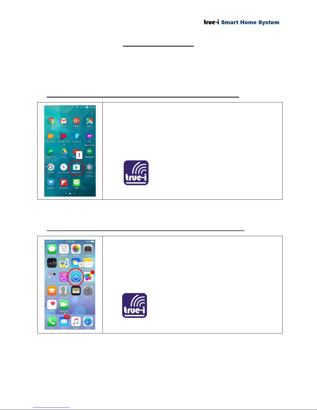
1) Go to “Play Store” to download “TrueEye SmartHome”
mobile application. User need to have a google/ gmail account
for downloading application from “Play Store”.
2) Key in “trueeye” in the search box at “Play Store”.
3) You can find “TrueEye SmartHome”. Click and download
accordingly.
1) Go to “App Store” to download “TrueEye SmartHome”
mobile application. User need to have an apple account for
downloading application from Apple “App Store”.
2) Key in “trueeye” in the search box at Apple “App Store”.
3) You can find “TrueEye SmartHome”. Click and download
accordingly.
1. Downloading Mobile Application
1.1 Downloading “TrueEye Smart Home” mobile application on Android
1.2 Downloading “TrueEye Smart Home” mobile application on Apple iOS
Page 1 of 37
Page 5
2. Creating an account and registration of serial number
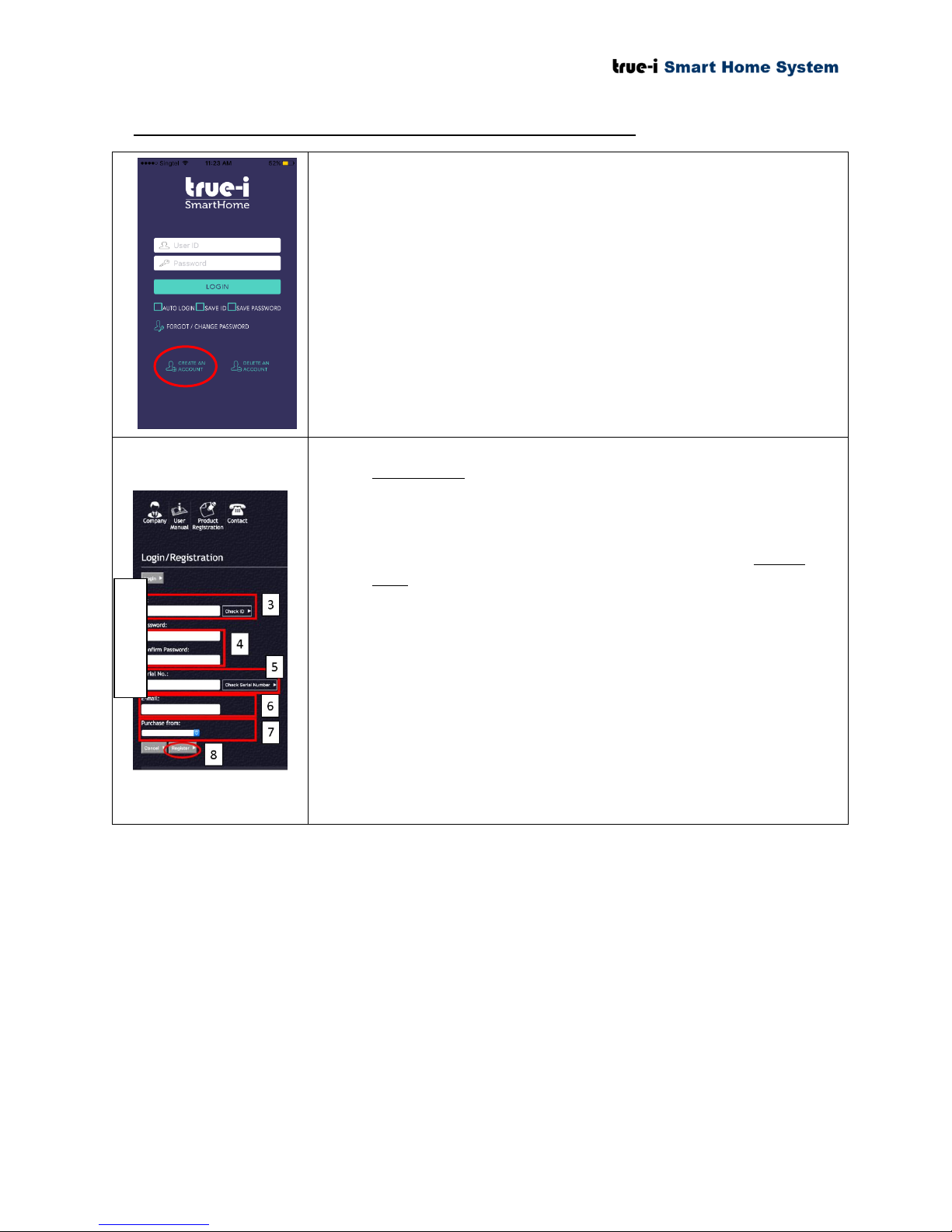
1) Open “True Eye SmartHome” mobile application.
2) Click “CREATE AN ACCOUNT.
3) At registration page, key in the user prefer ID. The user
MUST click “Check ID” to check if ID is available.
4) Choose the user prefer password and confirm the password.
5) Key in the True-i gateway serial number. The user MUST
click “Check Serial Number” to check whether the gateway is
registered.
Please omit “-” in putting the serial number in the box.
6) Key in the user email address.
7) Choose the “Purchase from” tab.
8) Click “Register” button.
*Note that all input fields are case sensitive
Registration
Page 2 of 37
Page 6
3. True-i gateway connection type
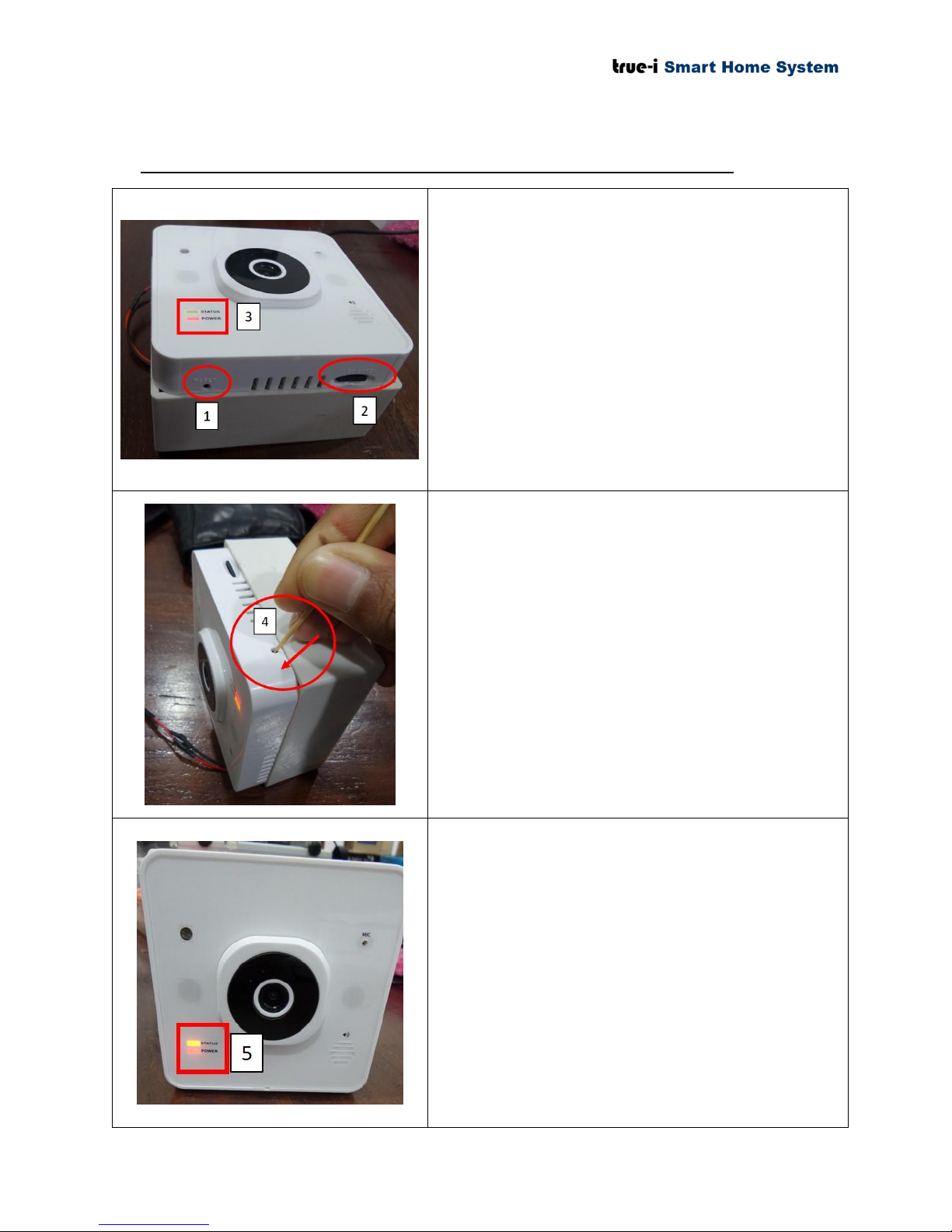
1) “RESET” button for switching to AP mode
connection.
2) Micro SD card slot for keeping video
recording and firmware upgrading.
3) “STATUS” LED and “POWER” LED for the
True-i gateway.
When pressing “RESET” button, it is
recommended to use a paperclip or sim
card extractor.
To access the gateway via AP mode, please do the
following steps.
4) Press the “RESET” button according to the
direction as shown in the figure with red
arrow line. Please take note that the user has
to feel the “PUSH” button on the device.
Please take note that the user has to press
and hold the “RESET” button for about 10
seconds until the user hear two beeping
sounds. In any case of user cannot hear the
two beeping sound, please power ‘OFF’
and ‘ON’ the gateway and wait for about 510 minutes to reconnect the gateway.
5) The status light of the gateway can be seen as
shown in the picture if the gateway is in AP
mode.
Status LED: Solid ORANGE
Power LED: Solid RED
More details on the LED light code can be
found in section 3.3 LED light code.
3.1 Access Point (AP) mode connection (For changing of user’s wifi setting)
Page 3 of 37
Page 7
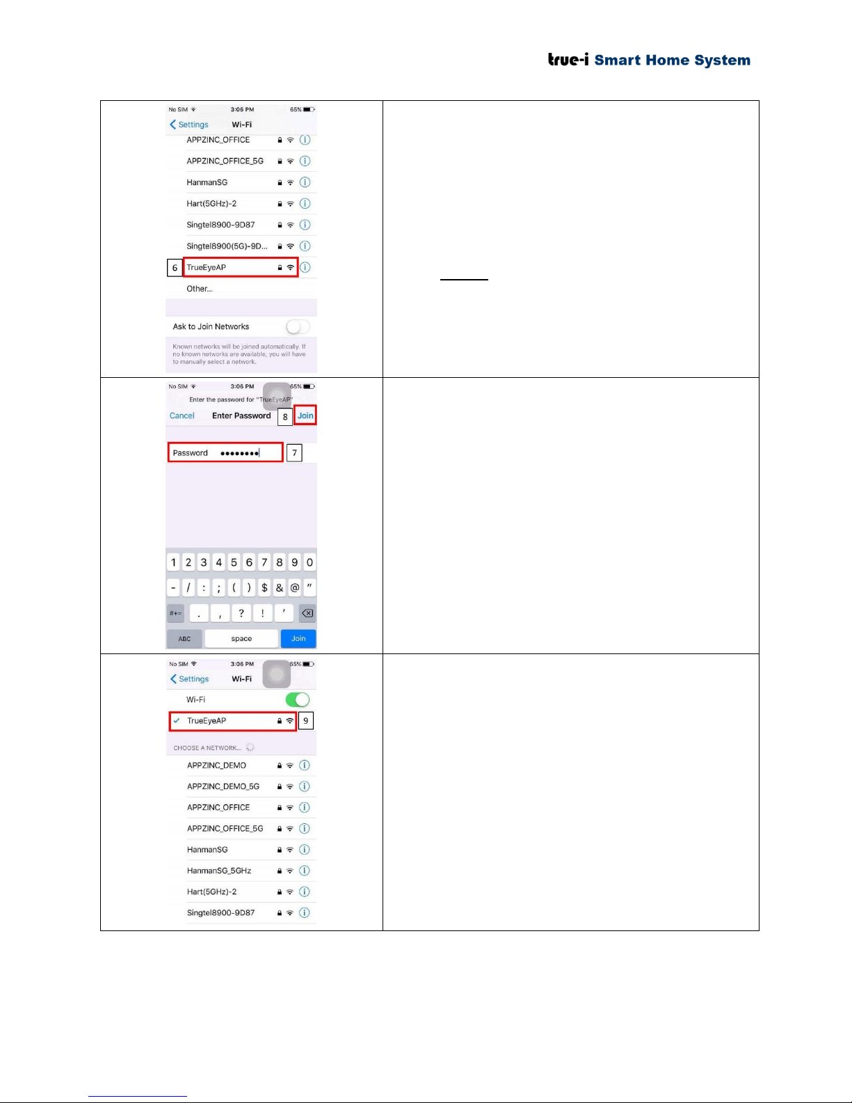
Once the gateway is in AP mode, look for gateway
default SSID to connect. The gateway default SSID is
“TrueEyeAP” as shown in the picture.
6) Click “TrueEyeAP” to connect from the
user’s mobile phone.
Please take note that “TrueEyeAP” SSID is
ONLY allowed to connect to one mobile
device each time the user connects.
7) Type the manufacturer default password
“12345678” for connecting to “TrueEyeAP”
SSID.
This manufacturer password cannot be changed.
8) Click “Join” to connect to “TrueEyeAP”
SSID.
9) The user can see as shown in the picture if the
user’s mobile phone is being connected to
“TrueEyeAP”.
In the case of the connection is
unsuccessful, please kindly check if there is
any other mobile phone that is connected to
“TrueEyeAP”. If it is difficult to find the
mobile, please restart the gateway and try
connecting again after the gateway is being
restarted.
Page 4 of 37
Page 8
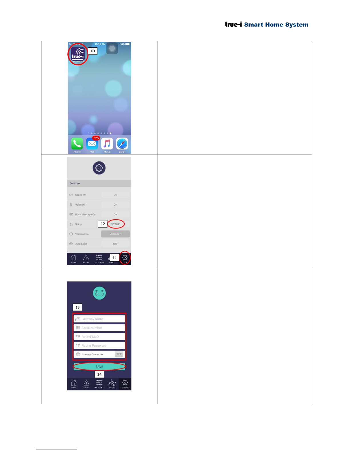
10) After connection is successful to
“TrueEyeAP” SSID, open “TrueEye Smart
Home” mobile application.
11) When the user connects in AP mode, the user
does not need to login ID and password. Click
“SETTING” page as shown in the picture.
12) Click “SETUP” to change the Wi-Fi
configuration setting.
13) Type in according to the instruction in “3.2
Internet connection setup”.
Please take note that “Router SSID” and
“Router Password” is case-sensitive.
For “Serial Number”, it will be case-
sensitive and please omit the dash “-”.
14) Click “SAVE” button.
The device will ask the user to restart the
gateway after clicking “SAVE” button. Please
restart the gateway for changes to take effect
of Wi-Fi configuration. Once it is restarted,
the gateway will be connected in “Internet
connection” mode.
Restarting the gateway can take about 5-10
minutes.
Page 5 of 37
Page 9
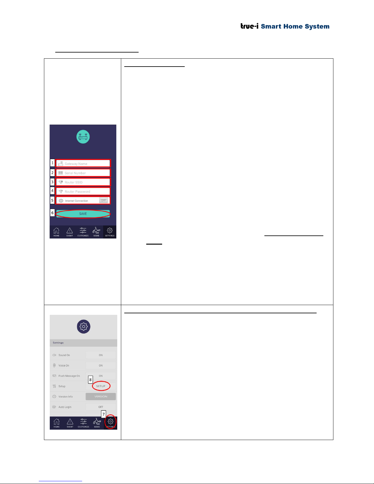
3.2 Internet connection setup
For first time setup
Connect to True-i gateway in access point (AP) mode. (See 3.1
Access Point (AP) mode connection for details.)
Open “TrueEye SmartHome” mobile application. For first time set
up, the following page will appear automatically as shown in the
picture.
1) Put prefer “Gateway Name”.
2) Put the “Serial Number”.
3) “Router SSID” should be user’s home Wi-Fi SSID.
4) “Router Password” should be user’s home Wi-Fi password.
5) Please click “OFF” button to switch “ON” for “Internet
Connection”. If the button is already “ON”, no further action
is required.
6) Click “SAVE” for saving the settings to communicate with
user’s home Wi-Fi hotspot.
*Note that all input are case sensitive
Please take note that Wi-Fi should be 2.4 GHz frequency
band. (Not compatible with 5 GHz frequency band)
The device will ask the user to restart the gateway after
clicking “SAVE” button. Please restart the gateway for
changes to take effect of Wi-Fi configuration. Once it is
restarted, the gateway will be connected in “Internet
connection” mode.
Restarting the gateway can take about 5-10 minutes.
For subsequent setup (if user’s Wi-Fi information is changed)
For subsequent setup for changing user’s Wi-Fi information, the user
has to put the True-i gateway to be in Access Point (AP) mode first.
(See 3.1 Access Point (AP) mode connection for details.)
Then, the user can access the above mentioned setup information as
follows:
7) Click “SETTING” on the mobile application
8) Click “SETUP” as shown in the figure to change the setting
accordingly as shown in the “For first time setup” information
page.
Please follow the steps mentioned above and to change the
‘Router SSID’ name and ‘Router Password’, please change
accordingly as in step (3), (4) and (6).
Page 6 of 37
Page 10
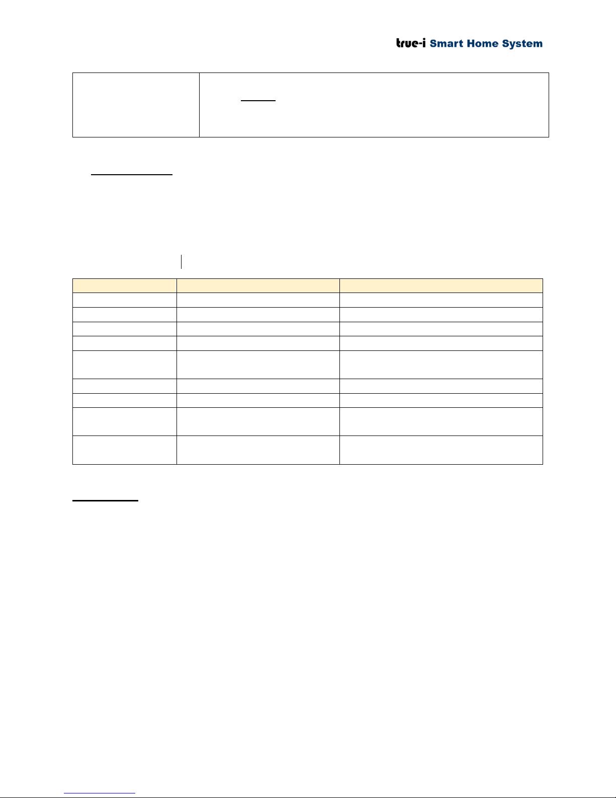
Please take note that the user can change the Wi-Fi setting
ONLY in AP mode.
LED Power Light
LED Status Light
Description
LED light OFF
LED light OFF
Gateway power is OFF.
RED light ON
LED Light OFF
Gateway is restarting.
RED light ON
ORANGE light ON
Gateway is in AP Mode.
RED light ON
ORANGE light (blinking once
a second)
Gateway is in AP Mode, No SD Card.
RED light ON
GREEN light ON
Gateway is connected to Internet.
RED light ON
GREEN light (blinking once a
second)
Gateway is connected to Internet, No
SD Card.
RED light ON
GREEN light (blinking twice a
second)
Gateway is not connected to Internet.
3.3 LED light code
There are two LED lights located on left corner of the gateway. The LED indication is as in the
following table.
Status LED light: ORANGE (OR) GREEN
Power LED light: RED
AP = Access P oint (Gateway acts as an access point)
REMARKS:
Turn on gateway one at a time in AP mode. ONLY ONE DEVICE is allowed to connect
to gateway in AP mode.
To include the components/ devices, the gateway and device should be within one meter.
Default AP for gateway: SSID: “TrueEyeAP”, Password “12345678”.
Must use original adapter that comes with the gateway.
In AP mode, the user is not allowed to unlock doorlock for safety reason.
To be able to use gateway using internet, the IP address should be public IP (i.e; IP
address at modem/ router should be the same as checking on user’s computer via “what is
my IP” website. Limitation is that some modem/ router cannot be displayed for public IP
address.
Page 7 of 37
Page 11
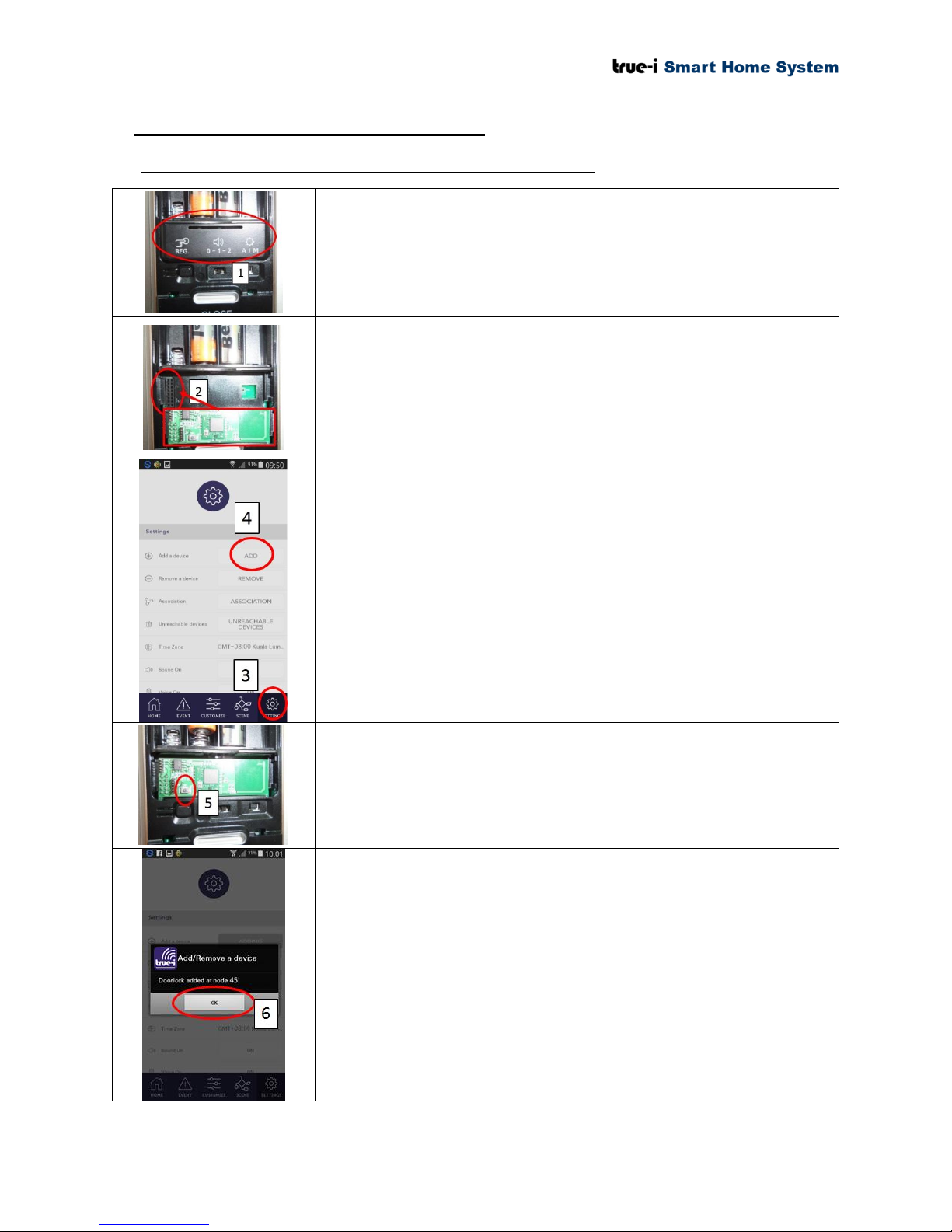
4. Inclusion of devices at True-i gateway
1) Remove the cover to insert the door lock controller module
(HMDM-100).
2) Insert the door lock module accordingly to the connection.
* Note: Ensure that the device is within 1 meter from the
True-i gateway for inclusion.
* Note: Please use Wi-Fi connection during inclusion
3) Open “TrueEye Smart Home” mobile application and click
on “Setting” as shown in the picture.
4) To include/ add the component/ device, click “ADD” as
shown in the picture.
* Note: Please wait until the loading is completed while
doing inclusion/ exclusion of devices and please do not
exit the application.
5) To include the device, please repeatedly press the small
push button until you receive the signal from “TrueEye
Smart Home” mobile application for confirmation on
adding the device/ component.
6) Click “OK” once the notification appeared as shown in the
picture.
After that, the device is included in the gateway for controlling
from “TrueEye Smart Home” mobile application.
4.1 Inclusion of door lock controller module (HMDM-100)
Page 8 of 37
Page 12
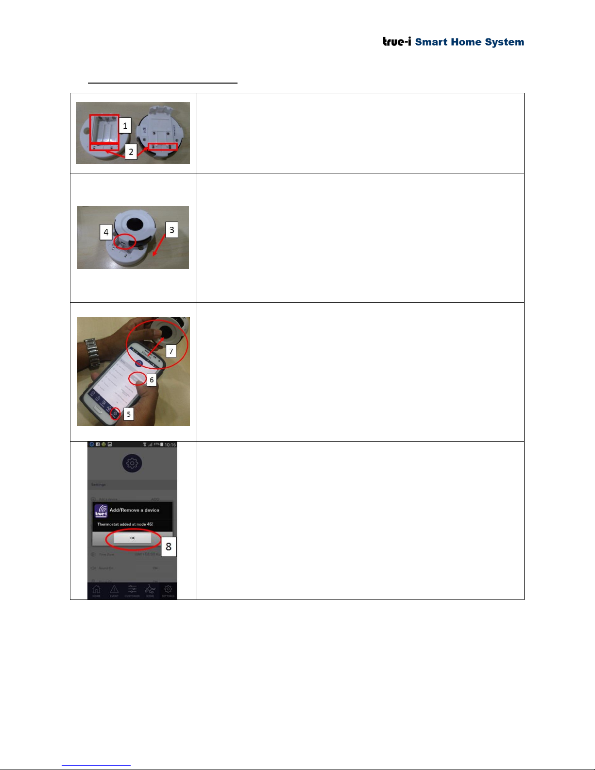
4.2 Inclusion of AC IR Extender
1) Put 3 x AAA Alkaline batteries into the batteries
compartment.
2) Make sure the contacts are protruded out correctly.
3) Assemble the sensor and battery compartment as shown in
the picture.
4) User can also use USB power cable to power the IR
extender instead of using batteries.
* Note: Ensure that the device is within 1 meter from the
True-i gateway for inclusion.
* Note: Please use Wi-Fi connection during inclusion
5) Open “TrueEye Smart Home” mobile application and click
on “Setting” as shown in the picture.
6) To include/ add the component/ device, click “ADD” as
shown in the picture.
* Note: Please wait until the loading is completed while
doing inclusion/ exclusion of devices and please do not
exit the application.
7) Press the black color push button in the center repeatedly
until you receive the signal from mobile application.
8) Click “OK” once the notification appeared as shown in the
picture.
After that, the device is included in the gateway for controlling
from “TrueEye Smart Home” mobile application.
Page 9 of 37
Page 13
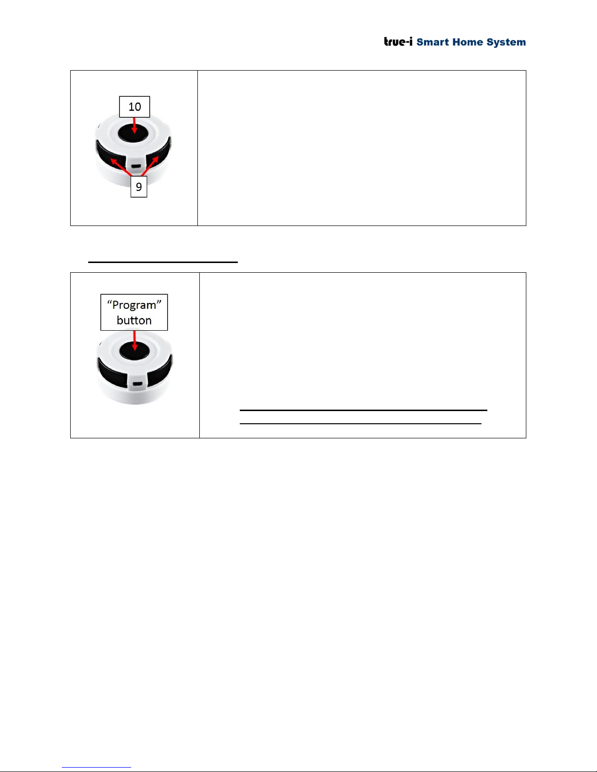
9) This portion of IR extender is for transmitting signal.
10) This portion of IR extender is for receiving signal while
adding/ inclusion of device or learning the code from
mobile application. It is also known as “Program” button.
Press and hold “Program” button for 10 seconds on IR extender.
The LED will flash twice until reset process is completed. Once IR
extender is being “factory reset”, you need to include the IR
extender to the gateway again and learn the code again.
* Note: Please exclude/ remove the IR extender from the
gateway first before you reset the IR extender. Once you
reset it, the IR extender previously added in the gateway
will be shown as “Unreachable Device”. Therefore, please
ensure to exclude/ remove the IR extender from the
gateway before you do factory reset to IR extender.
4.3 Factory reset of IR Extender
Page 10 of 37
Page 14
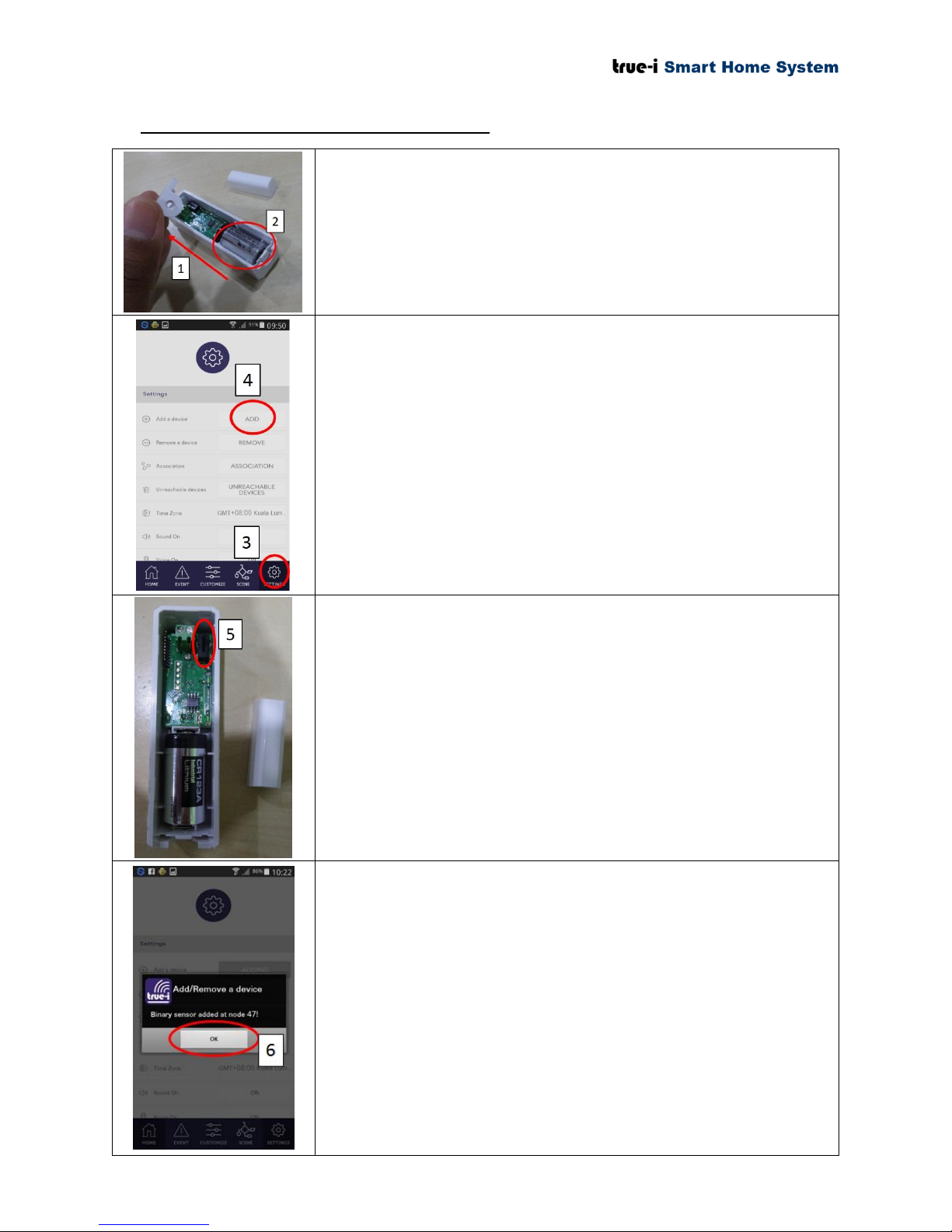
4.4 Inclusion of door/ window Contact Sensor
1) Open the cover of door/ window contact sensor.
2) Put CR123A Lithium battery into the battery compartment.
* Note: Ensure that the device is within 1 meter from the
True-i gateway for inclusion.
* Note: Please use Wi-Fi connection during inclusion
3) Open “TrueEye Smart Home” mobile application and click
on “Setting” as shown in the picture.
4) To include/ add the component/ device, click “ADD” as
shown in the picture.
* Note: Please wait until the loading is completed while
doing inclusion/ exclusion of devices and please do not
exit the application.
5) To include the device, please press small push button
repeatedly until you receive the signal from “TrueEye
Smart Home” mobile application for confirmation on
adding the device/ component.
6) Click “OK” once the notification is appeared as shown in
the picture.
After that, the device is included in the gateway for controlling
from “TrueEye Smart Home” mobile application.
Page 11 of 37
Page 15
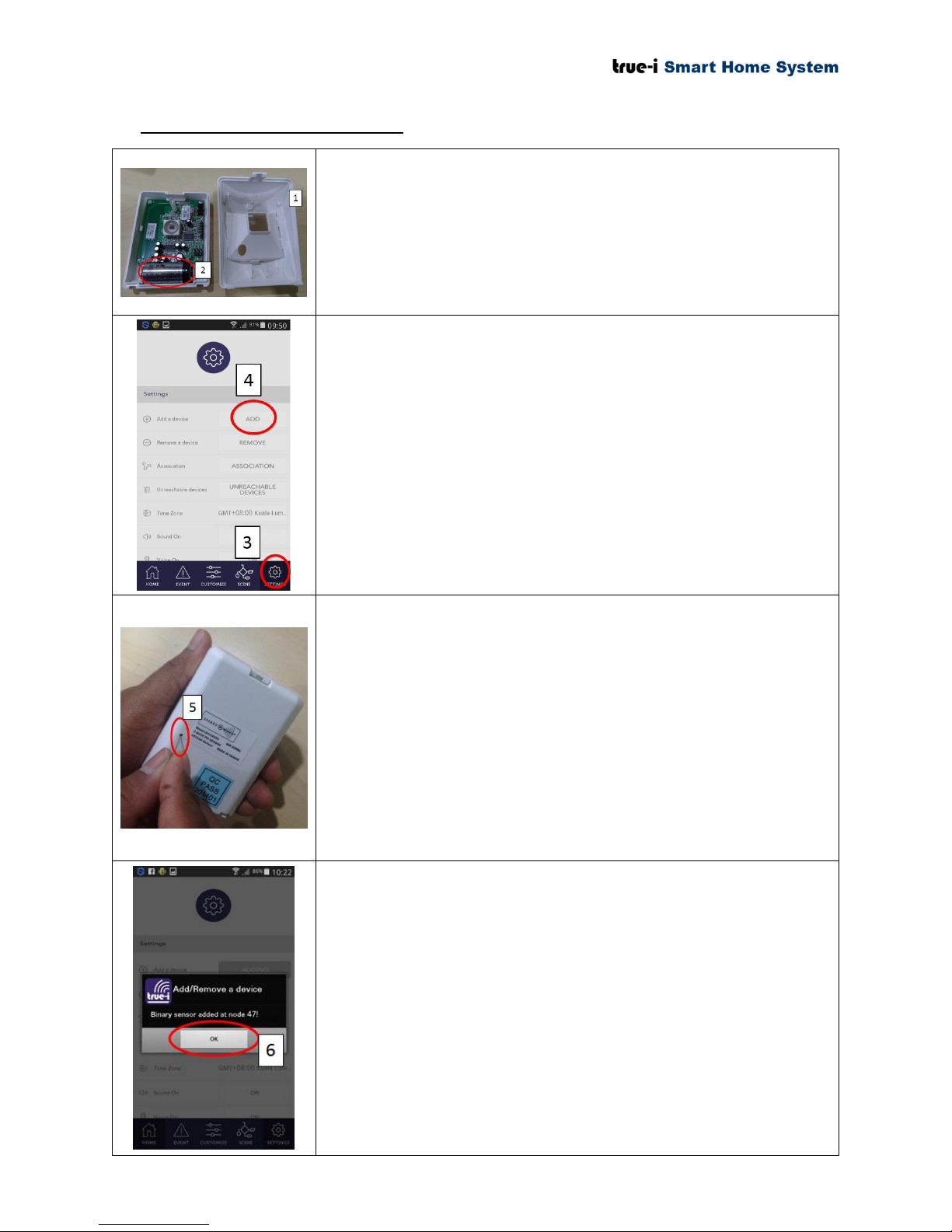
4.5 Inclusion of PIR Motion Sensor
1) Open the cover of door/ window contact sensor.
2) Put CR123A Lithium battery into the battery compartment.
* Note: Ensure that the device is within 1 meter from the
True-i gateway for inclusion.
* Note: Please use Wi-Fi connection during inclusion
3) Open “TrueEye Smart Home” mobile application and click
on “Setting” as shown in the picture.
4) To include/ add the component/ device, click “ADD” as
shown in the picture.
* Note: Please wait until the loading is completed while
doing inclusion/ exclusion of devices and please do not
exit the application.
5) To include the device, use a paperclip or sim card extractor
and please press the button on the rear of the device (as
shown in the picture) repeatedly 3 times per second, until
you receive the signal from “TrueEye Smart Home” mobile
application for confirmation on adding the device/
component. The case shall be opened while adding the
device.
6) Click “OK” once the notification appeared as shown in the
picture.
After that, the device is included in the gateway for controlling
from “TrueEye Smart Home” mobile application.
Page 12 of 37
Page 16
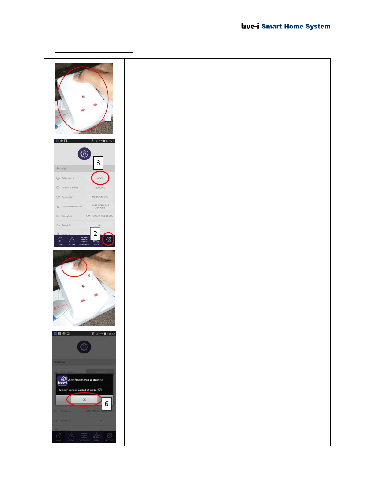
4.6 Inclusion of Smart Plug
1) Connect the smart plug to AC power outlet.
* Note: Ensure that the device is within 1 meter from the
True-i gateway for inclusion.
* Note: Please use Wi-Fi connection during inclusion
2) Open “TrueEye Smart Home” mobile application and click
on “Setting” as shown in the picture.
3) To include/ add the component/ device, click “ADD” as
shown in the picture.
* Note: Please wait until the loading is completed while
doing inclusion/ exclusion of devices and please do not to
exit the application.
4) To include the device, please press small push button
repeatedly until you receive the signal from “TrueEye
Smart Home” mobile application for confirmation on
adding the device/ component.
5) Click “OK” once the notification appeared as shown in the
picture.
After that, the device is included in the gateway for controlling
from “TrueEye Smart Home” mobile application.
Page 13 of 37
Page 17
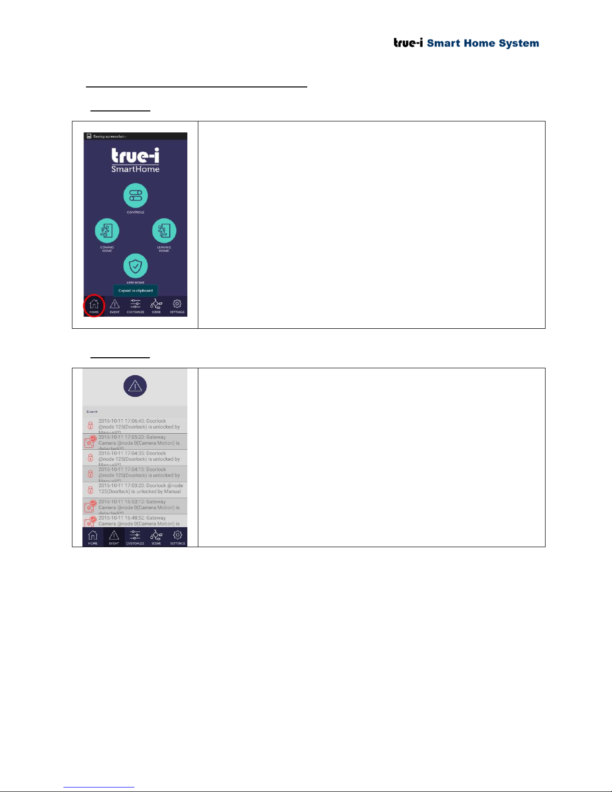
5. Navigating True-i mobile application
When the “Home” button is pressed, user can see the True-i “Home
page” of the mobile application.
Controls: Main control panel for viewing of different smart home
devices. To access individual devices, click the “CONTROLS” icon.
Coming Home/ Leaving Home: To activate leaving home/coming
home settings, click on the respective icon. Setting can be done under
“Customize” option between “Event” and “Scene”.
Arm Home: To arm with alarm when you are outside of the house.
To engage alarm systems, click the “Arm Home” icon. To “ARM”
the respective camera or respective sensor, please set the desired
sensor to “ON” at “Sensor” page which can be found under
“CONTROLS” icon. (See 5.14 Sensor page)
To check the status of your device, click “Event” tab below as shown
in the figure.
5.1 Home page
5.2 Event page
Page 14 of 37
Page 18
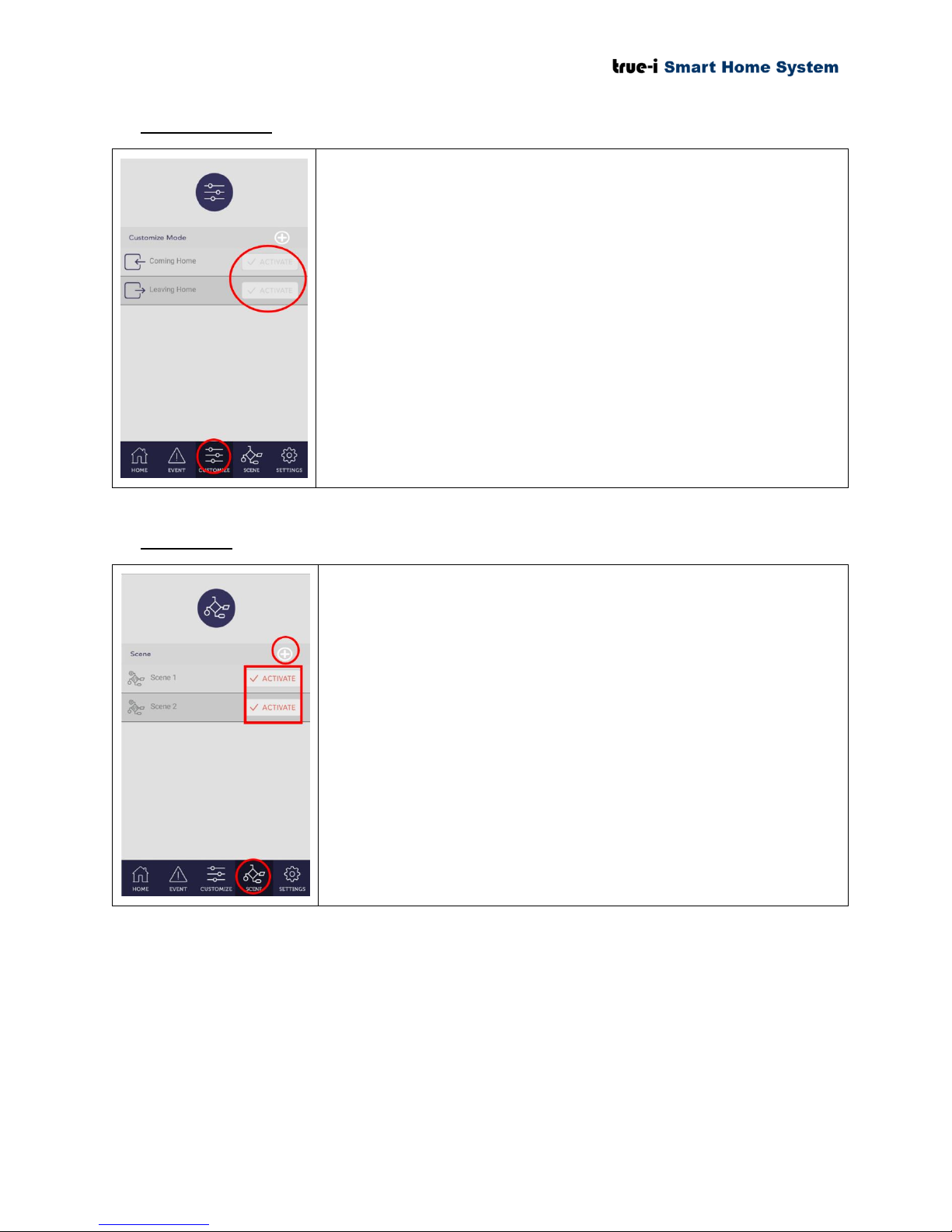
5.3 Customize page
To activate “Coming Home” or “Leaving Home” function to be used
at the “Home page”.
Click the activate button and test on the defined setting.
The user can set certain motion to activate specified actions. (E.g.
closing the door will off the lights.)
To create a new scenario, click the “+” button on the top
right.
Device will prompt user to select conditioning device (Door
lock, binary sensor, etc.)
Select the desired conditioning device.
Once done, device will prompt user to select the device that
will be activated/deactivated by conditioning device
Click save button to save scene
Scene will appear on scene page.
Click “ACTIVATE” to turn scene on.
5.4 Scene page
Page 15 of 37
Page 19
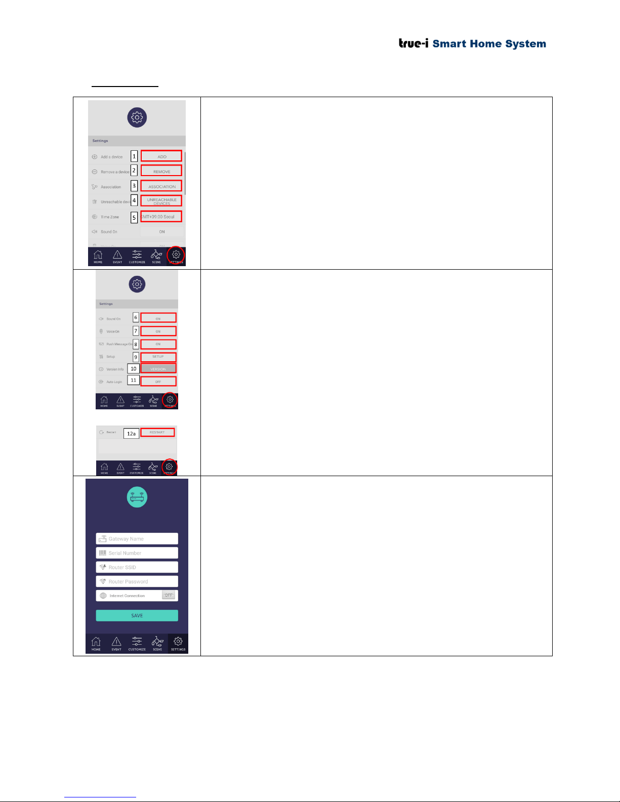
5.5 Setting page
1) For device(s) addition/ inclusion, click “ADD” button.
2) To remove/ excluding the device(s), click “REMOVE”
button.
3) Association of devices (used by installers)
4) For device(s) that user does not use for a certain time, the user
can put device(s) under “UNREACHABLE DEVICE” option.
To restore the device, the user can go into this option to
restore the device for usage or to control again.
5) Time zone setting can be changed depending on the gateway
location.
6) To turn on sound notification, click “ON” button.
7) To turn on voice, click “ON” button.
8) To receive push notification, click “ON” button.
9) To enter the setup page, click “SETUP” button.
10) To get check for version click “VERSION” button.
11) To activate auto login click “ON” or “OFF” button, depending
on user’s preference.
12a) To restart the gateway from the mobile application.
Any changes in the user’s home Wi-Fi settings, the user have to press
“Reset” button to go into AP mode. Thus, it can be changed in the
“SETUP” page under “SETTING” tab.
Please restart the gateway and mobile application after changing the
Wi-Fi connection settings.
Page 16 of 37
Page 20
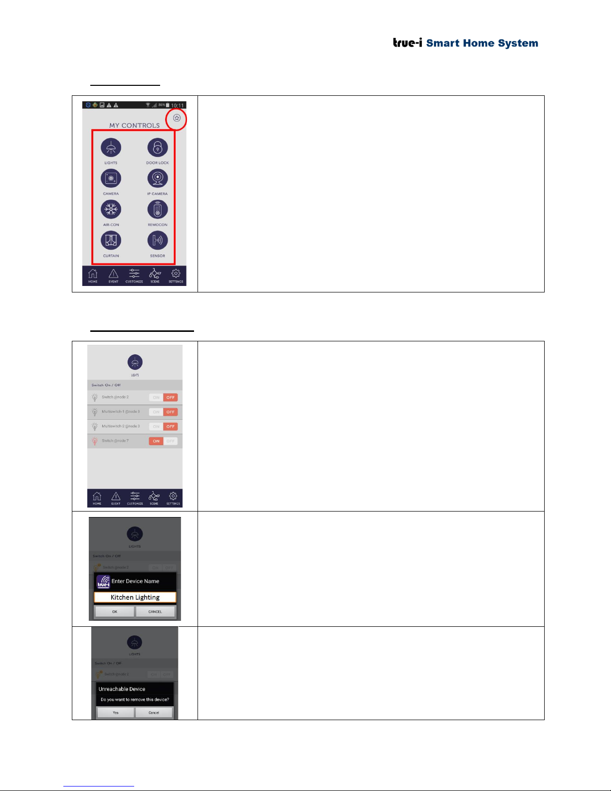
5.6 Control page
User can save the frequently used icon under “Favourite” page at the
upper right corner of “My Controls” page.
The user can control the devices according to the options. The user
can access these devices in the control page:
Lights
Door Lock
Camera
IP camera
Air-conditioner
Remote Control
Curtains
Sensors
To switch lights “ON” or “OFF”, click “ON” or “OFF” button
respectively.
To check status of connected lights, click the light bulb icon.
‘Orange’ means connected with “ON” position.
‘Grey’ means connected with “OFF” position.
‘Orange with exclamation’ sign means not connected.
To rename the light switch, press and hold the text area, the text box
will pop up as shown in the picture. The user can then change the
preferred name. The name change will only reflects on individual
personal mobile phone.
* Please take note that changing Name for device/ customize
option (except changing “Scene” Name) in mobile app is
only reflecting on individual personal mobile phone.
To remove switches that are not in range, press and hold light bulb
icon, the prompt will pop up as shown in the picture. Click “Yes” if
the user wishes to put the device temporarily under “Unreachable
Device”.
5.7 Lights control page
Page 17 of 37
Page 21
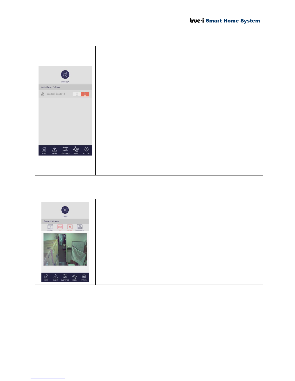
5.8 Door lock control page
To “LOCK” or “UNLOCK”, click “LOCK” or “UNLOCK” button
respectively.
To check status of connected door lock see the padlock icon.
‘Grey’ means connected with “ON” or “OFF” position.
‘Orange with exclamation’ sign means not connected.
To rename the door lock, press and hold the text area, the text box
will pop up, user will then be able to change the preferred name. The
name change will only reflects on individual personal mobile phone.
* Please take note that changing Name for device/ customize
option (except changing “Scene” Name) in mobile app is
only reflecting on individual personal mobile phone.
To remove door lock that are not in range, press and hold padlock
icon, the prompt will pop up. Click “Yes” if the user wishes to put the
device temporarily under “Unreachable Device”.
The built-in camera detects and record motion when armed.
To view previous recordings, click “PLAYBACK” icon.
For real time viewing, click “GATEWAY” icon.
For viewing of door viewer, click “DOOR CAMERA” icon.
To delete video, press and hold video recording
5.9 Gateway camera page
Page 18 of 37
Page 22
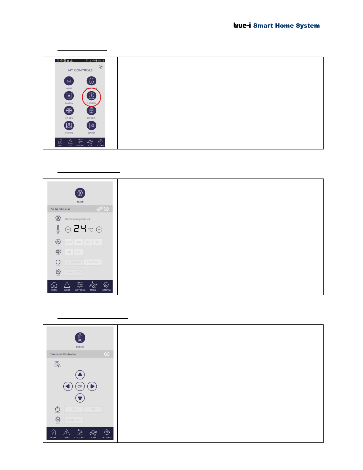
5.10 IP camera page
As shown in the figure, clicking the “IP CAMERA” icon on the
control page, it will lead the user to “SmartCam” mobile application
or download page of the mobile application if the user have yet to
install the “SmartCam” application.
The user will have to download “SmartCam” mobile application, if
he/she has installed the IP camera at home.
Various controls for air-conditioner (aircon) can be accessed in the
aircon control page as shown in the picture.
To adjust the temperature, click “+” or “–” icon.
To set the speed of aircon fan, click “LOW”/ “MID”/
“HIGH” icon.
To turn “ON”/ “OFF” for blower, click “ON”/ “OFF”
button.
To turn “ON”/ “OFF” the aircon, click “ACTIVATE”/
“DEACTIVATE” button respectively.
To learn about the air- con codes, click the learn code
button.
To use smart phone as a remote control via True-i gateway, click the
“REMOCON” icon on the control page.
The user will see “Remocon control” page as shown in the figure.
5.11 Aircon control page
5.12 Remocon control page
Page 19 of 37
Page 23
5.13 Curtain control page
Click “CLOSE” button to close the curtain.
Click “OPEN” button to open the curtain.
Click “FULL CLOSE” button to completely close the
curtain.
Click “FULL OPEN” button to completely open the curtain.
Click “SET” button to set what time to open and close the
curtain.
Putting “ON” for sensor means, the user will get the notification
when the motion is detected on the gateway or when the sensor is
being triggered depending on the user pre-defined option.
The sensors which are in “ON” mode at sensor page will
send the notification to users when the user put “ARM”
mode. (See 5.1 Home page)
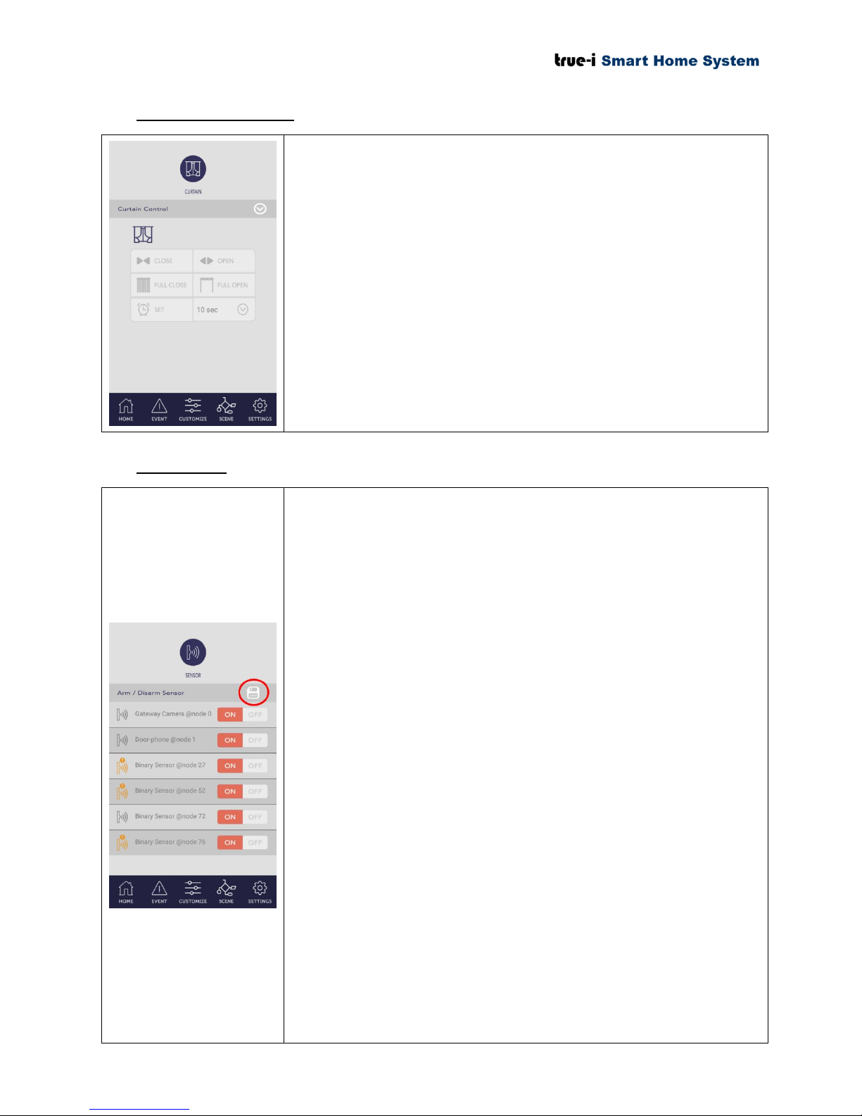
To Activate/Deactivate sensor click the “ON” or “OFF” button
respectively. Click “SAVE” icon at the upper right corner as shown
in the picture, after setting the sensor.
To check status of connected sensors see the sensor icon.
‘Orange’ means connected but sensor is in open position or
motion is detected.
‘Grey’ means sensor is in closed position or no motion.
‘Orange with exclamation’ sign means sensor in not
connected.
To rename the sensor, press and hold the text area, the text box will
pop up and user will be able to change the name. The name change
will only reflects on individual personal mobile phone.
* Please take note that changing Name for device/
customize option (except changing “Scene” Name) in
mobile app is only reflecting on individual personal
mobile phone.
To remove sensor that are not in range, press and hold sensor icon, a
pop up will appear. Click “Yes” if the user wishes to put the device
temporarily under “Unreachable Device”.
5.14 Sensor page
Page 20 of 37
Page 24
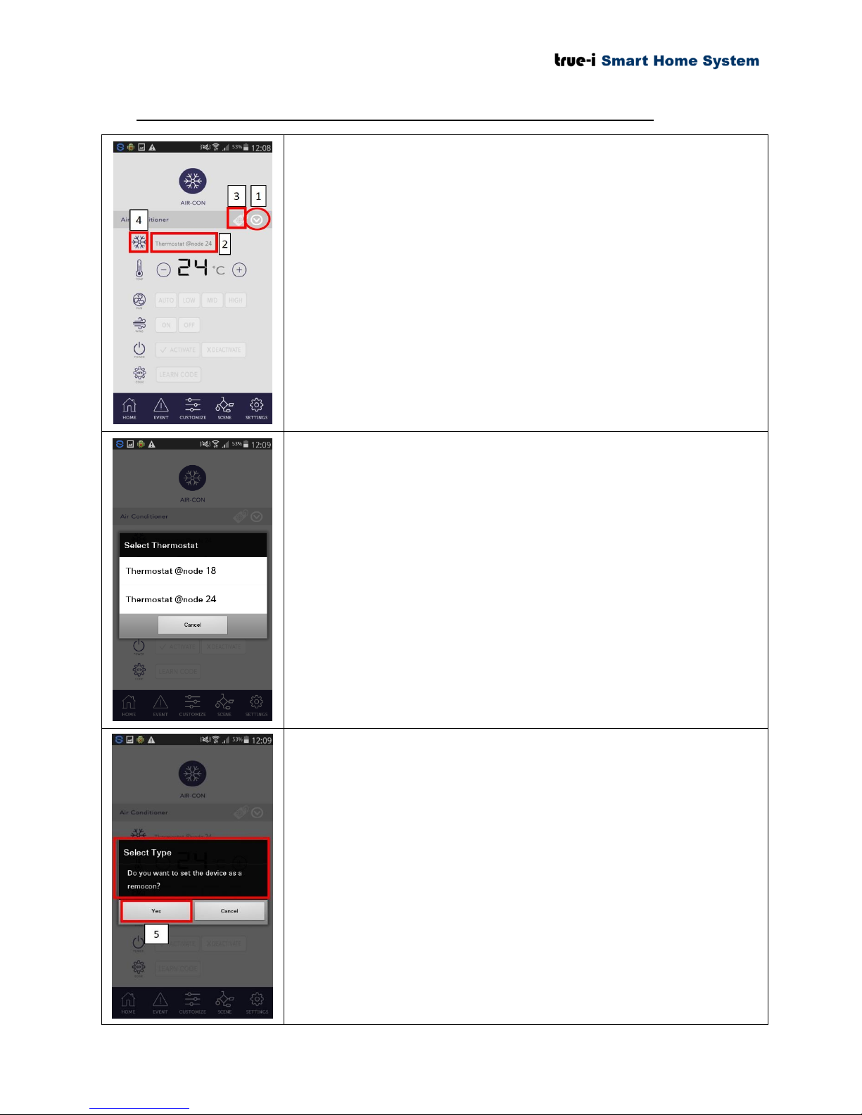
5.15 How to switch IR extender for controlling Aircon and Remocon page
As a default, IR extender device will be able to see in “Aircon”
control page.
1) Click this icon for selection of included IR extender devices.
If the user has more than one IR extender, the user has to
choose the respective IR extender from this menu for
controlling the device.
2) The IR extender the user choose will appear in this place.
3) Click this icon to choose the Aircon type according to user’s
installation at their homes.
4) Click “Aircon” icon for switching IR extender from
‘Aircon’control page to ‘Remocon’ control page.
When the user presses “No.1” icon as described in the ‘Aircon’
control page, the total number of installed IR extenders will be
appeared as shown in the picture.
Please take note that for the IR extenders that is already switched to
‘Remocon’ control page, cannot be seen in ‘Aircon’ control page.
When the user presses “No.4” icon as described in the ‘Aircon’
control page, the pop up message “Do you want to set the device as
an remocon?” will appear for the user to confirm on setting the IR
extender to be used under ‘Remocon’ control page.
5) Click ‘Yes’ if the user confirms to switch IR extender from
‘Aircon’ control page to ‘Remocon’ control page.
‘Aircon’ control page is to control the Air-conditioning
system at the user’s premises (office or home).
‘Remocon’ control page is to control the IR devices that
comes with remote control such as Television and fan with
IR remote control.
Page 21 of 37
Page 25
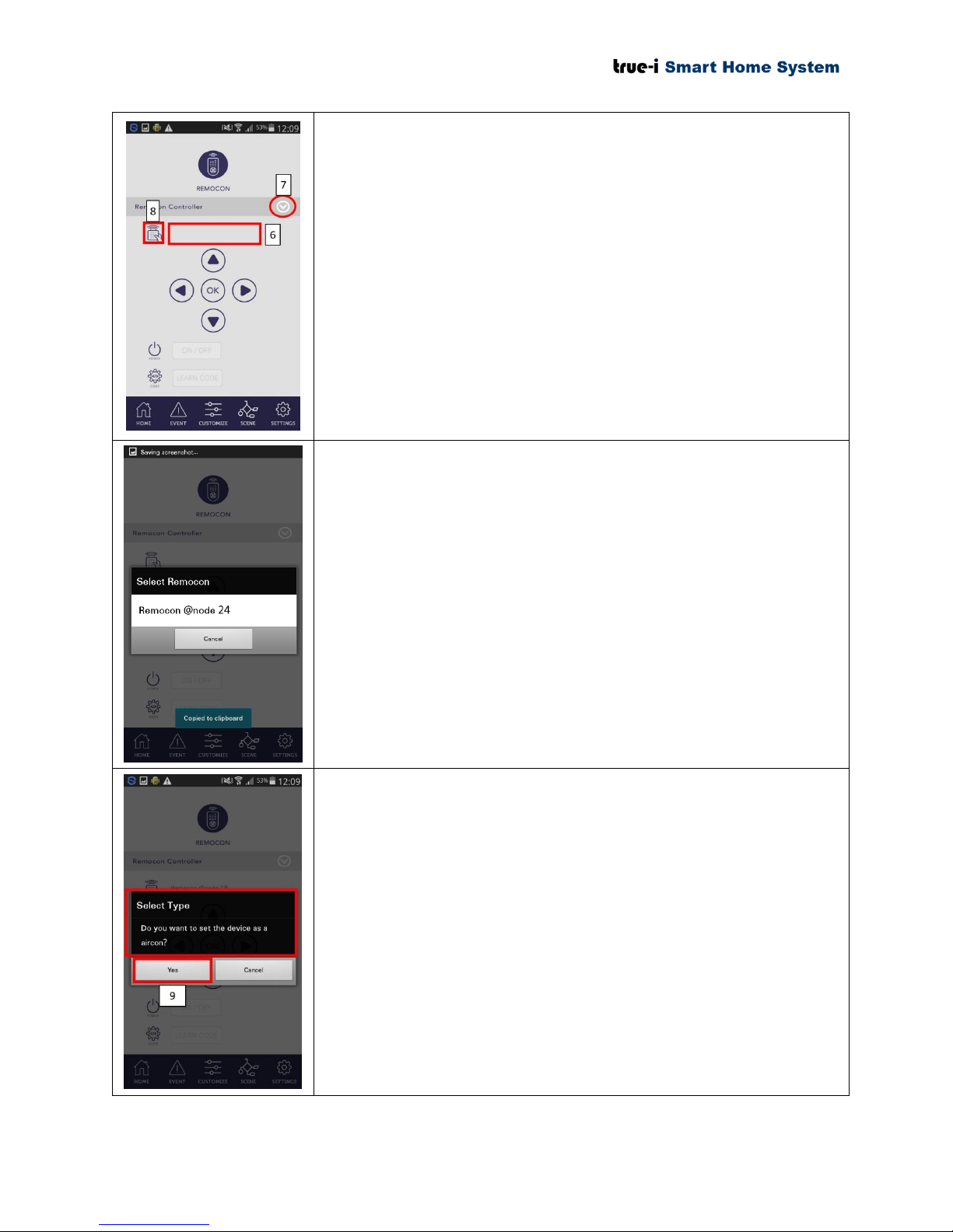
6) As a default, there is no IR extender will be seen as shown in
the picture.
7) Click this icon for selection of IR extender devices that is
switched to ‘Remocon’ control page.
8) Click “Remote” icon for switching IR extender from
‘Remocon’ control page to ‘Aircon’ control page.
When the user presses “No.7” icon as described in the ‘Remocon’
control page, the number of IR extenders that is switched to
‘Remocon’ control page, will be appeared as shown in the picture.
Please take note that for the IR extenders that is already switched to
‘Aircon’ control page, cannot be seen in ‘Remocon’ control page.
When the user presses “No.8” icon as described in the ‘Remocon’
control page, the pop up message “Do you want to set the device as
an aircon?” will appear for the user to confirm on setting the IR
extender to be used under ‘Aircon’ control page.
9) Click ‘Yes’ if the user confirms to switch IR extender from
‘Remocon’ control page to ‘Aircon’ control page.
‘Aircon’ control page is to control the Air-conditioning
system at the user’s premises (office or home).
‘Remocon’ control page is to control the IR devices that
comes with remote control such as Television and fan with
IR remote control.
Page 22 of 37
Page 26
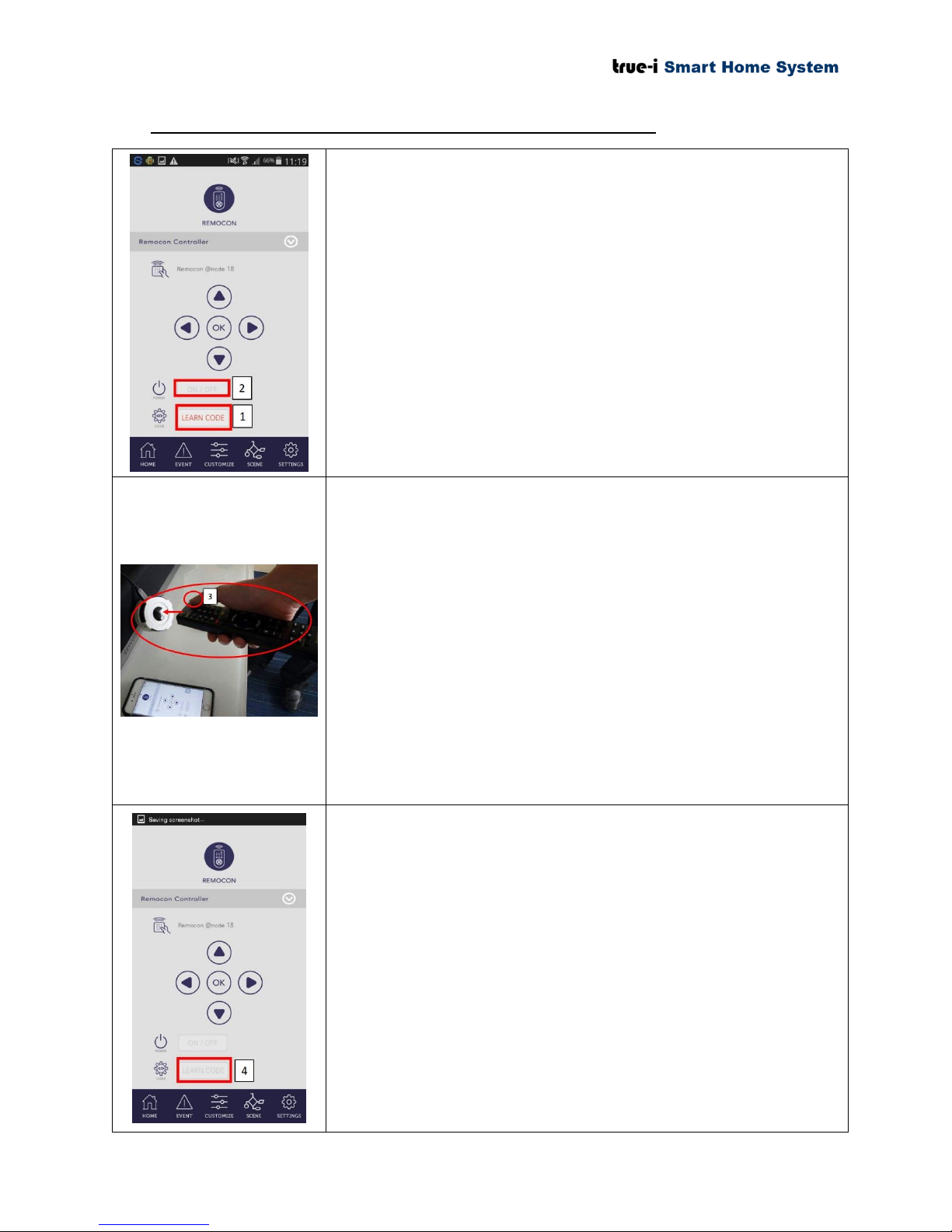
5.16 Learning code for remote control on ‘Remocon’ control page
To do learning code for remote control, the user has to go to
‘Remocon’ control page under “CONTROLS” option from the
‘Home’ page.
Please ensure that the device (e.g; Television or fan) should be
turned “ON” when the user do learning code. After turning “ON”,
please do the following procedures.
1) Click “LEARN CODE” as shown in the picture. Once it is
pressed, it should be highlighted as in ‘Orange’ color.
2) Click the desired button by user to learn the code. (In this
example, we are learning the code for Television ‘ON’/
‘OFF’ button.)
3) After clicking the desired button, please point the remote
controller to the middle of IR extender as shown in the
picture and click ‘ON’/ ‘OFF’ button as shown in the
picture. The user will see RED LED is flashing at IR
extender (for about 2 seconds) if learning code is
successful.
It is recommended that the user should point to opposite
direction with the device so as not to have any conflict on
learning the code by IR extender.
4) Click “LEARN CODE” after the user has done step (3).
“LEARN CODE” button should be grey off as shown in the
picture.
For learning code for other buttons on the remote control
(such as volume up and down, changing channel, etc), the
user has to repeat the above steps with the respective button
the user is desired to register.
Due to the limitation of the interface in the ‘Remocon’
control page, the user can only register up to 6 buttons for
controlling the device, which includes ‘ON’/ ‘OFF’ button.
Page 23 of 37
Page 27
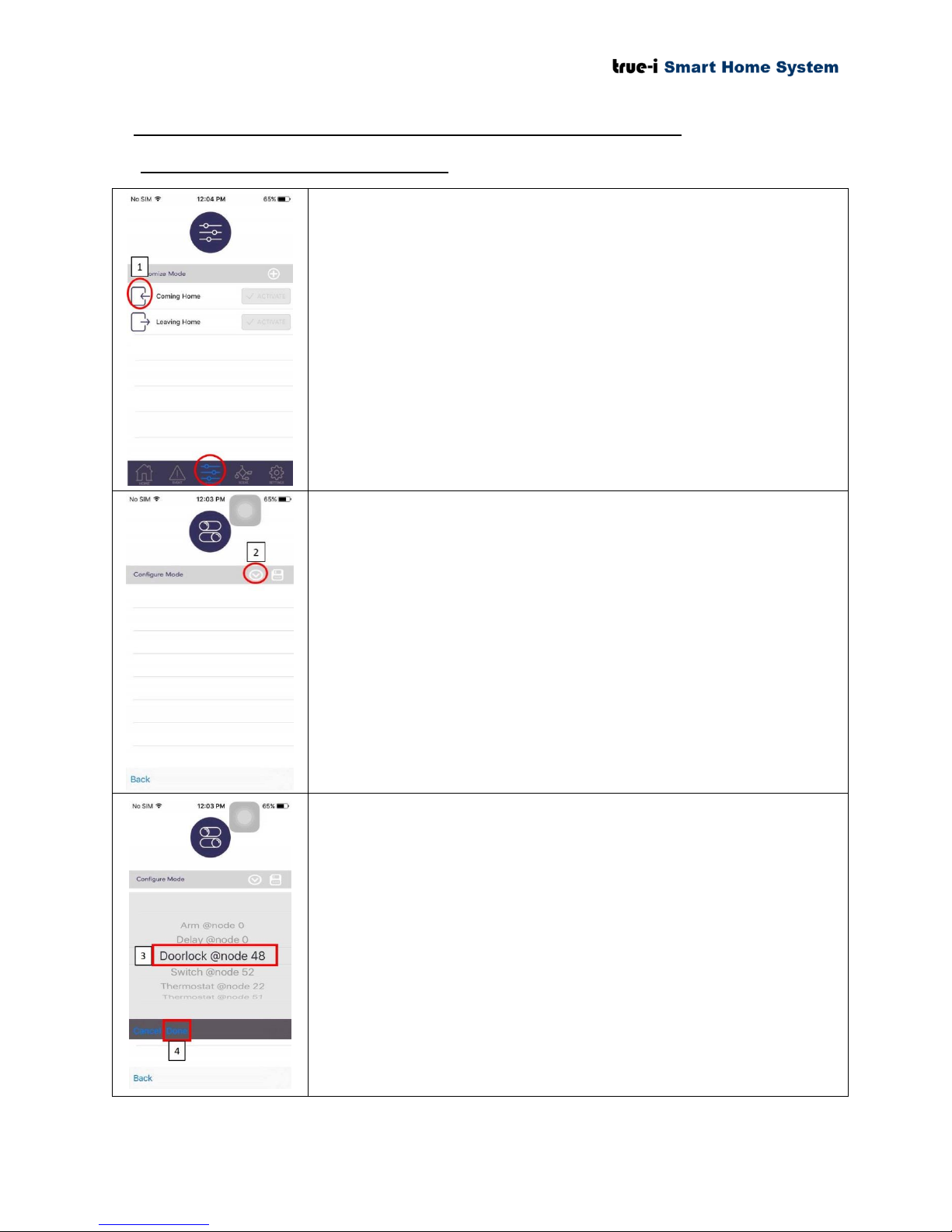
6. Customizing “Coming Home” and “Leaving Home” option
“Coming Home” and “Leaving Home” options can be customized
under “CUSTOMIZE” page as shown in red circle. After
customization is done, the user can click to activate the “Coming
Home” and “Leaving Home” buttons at “Home page” of the
“TrueEye Smart Home” mobile application.
1) Click “Coming Home” icon for configuration on “Coming
Home” option.
2) Click the icon as shown in the picture for selecting the options
to choose for customization.
In this example, it will be configured as when the user presses
“Coming Home” button, the door will be unlocked and the light
switch will be turned “ON”.
The user can choose any node for the desired option.
3) Choose “Doorlock @ node 48” in this example.
4) Click “Done” button after selection.
6.1 Customizing “Coming Home” option
Page 24 of 37
Page 28
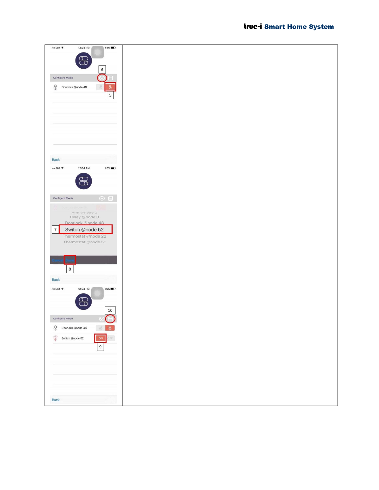
5) Click door “unlock” icon according to this example.
6) Click the icon to choose for selecting the second option for
this example.
7) Choose “Switch @ node 52” in this example.
8) Click “Done” button after selection.
9) Click “ON” button according to this example.
10) Click “Save” icon to save the “Coming Home” setting.
Page 25 of 37
Page 29
6.2 Customizing “Leaving Home” option
“Coming Home” and “Leaving Home” options can be customized
under “CUSTOMIZE” page as shown in red circle. After
customization is done, the user can click to activate the “Coming
Home” and “Leaving Home” buttons at “Home page” of the
“TrueEye Smart Home” mobile application.
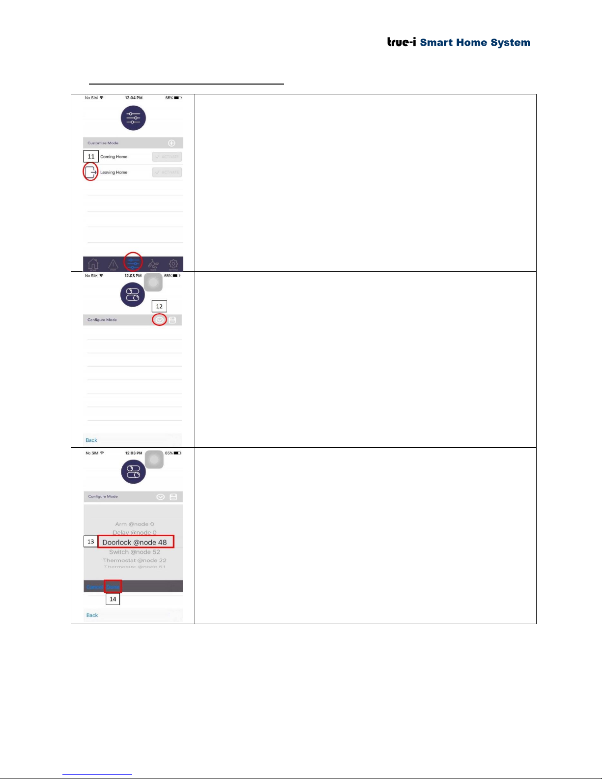
11) Click “Leaving Home” icon for configuration on “Leaving
Home” option.
12) Click the icon as shown in the picture for selecting the options
to choose for customization.
In this example, it will be configured as when the user presses
“Leaving Home” button, the door will be locked and the light
switch will be turned “OFF”.
The user can choose any node for the desired option.
13) Choose “Doorlock @ node 48” in this example.
14) Click “Done” button after selection.
Page 26 of 37
Page 30
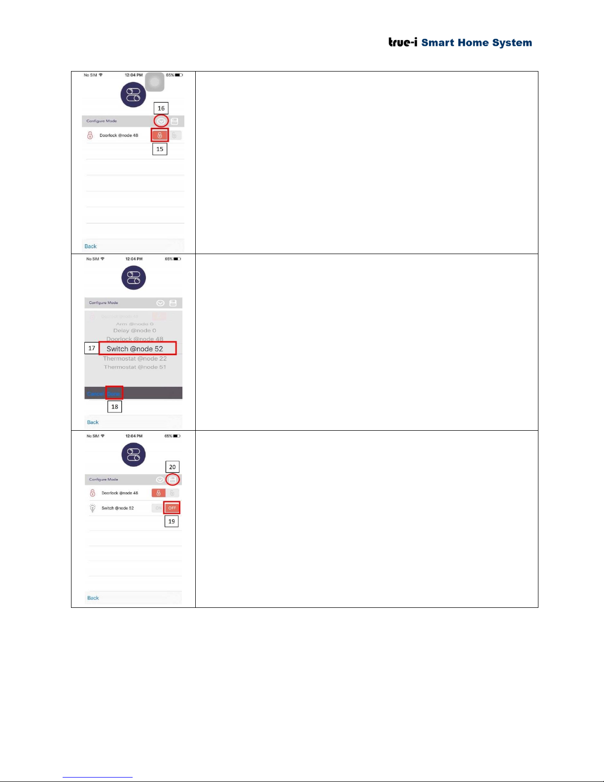
15) Click door “lock” icon according to this example.
16) Click the icon to choose for selecting the second option for
this example.
17) Choose “Switch @ node 52” in this example.
18) Click “Done” button after selection.
19) Click “OFF” button according to this example.
20) Click “Save” icon to save the “Leaving Home” setting.
Page 27 of 37
Page 31
7. How to configure “Scene” page
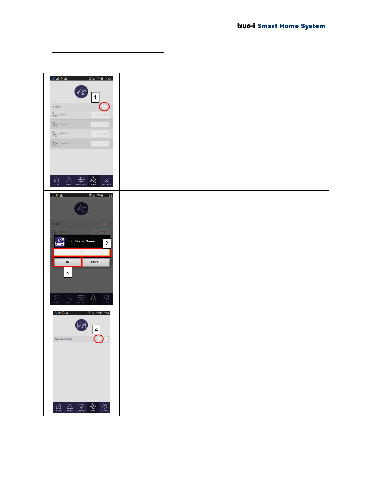
“Scene” page is mainly for allowing the users to create simple
conditional statements. This option is also known as IFTTT (“If This
Then That”) option.
1) Click “+” sign, for new “Scene” configuration.
2) There will be a pop up box to enter new “Scene” Name.
Please type the desired name for your “Scene” configuration.
3) Click “OK” after typing the name.
4) Click the button to choose for creating first (main) condition.
7.1 Configuration in Android mobile application
Page 28 of 37
Page 32
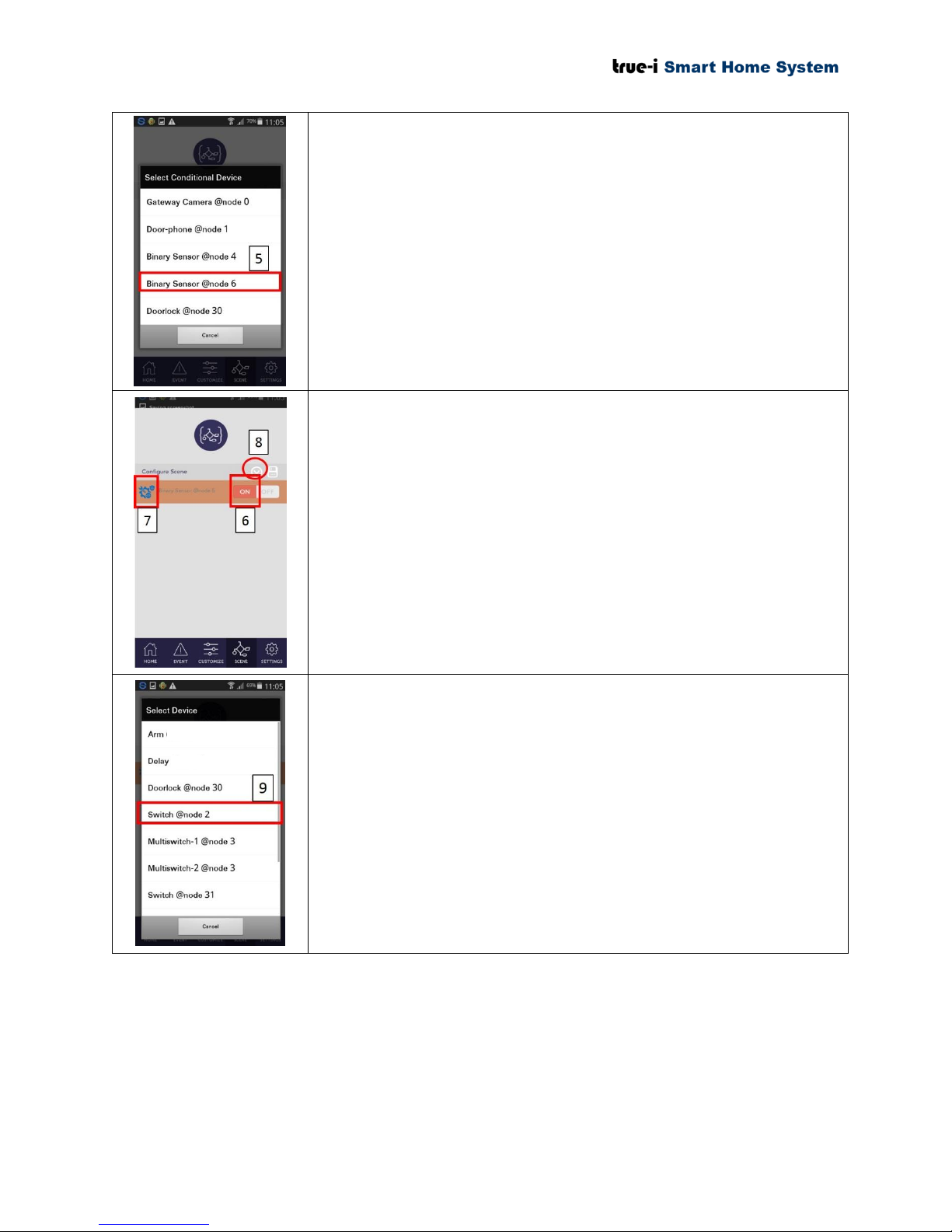
In this scenario, if the door contact sensor node is triggered (door is
opened), the light switches will be “ON”.
5) Choose “Binary Sensor @ node 6” which is door contact
sensor in this scenario.
6) Click “ON” for opening the door. If the user is triggering for
closing position of the door, the user has to choose “OFF”.
7) You will see the first (main) triggering option. Please tap the
icon to change the conditional statements on when it should
follow the conditional sequence set by the user.
Blue (as shown in the picture): Condition will trigger
both in “ARM” mode and “UN-ARM” mode.
Orange: Condition will trigger only in “ARM” mode.
Grey: Condition will trigger only in “UN-ARM”
mode.
8) Click the button to choose for the second sequence to follow
(e.g.; after opening the door, the light switch will be turned
“ON”).
9) In this scenario, “Switch @ node 2” will be chosen. The user
can choose any node for the desired option.
Arm: To put “ARM” to enable “Arm Home” mode.
Under Arm Home mode, the user will get notifications
when motion is detected by the gateway camera or when
the sensor is being triggered depending on the user predefined option.
Delay: To put delay for one sequence after another.
Please ensure that the sequence should not be conflict
with each other from one “Scene” to another “Scene”.
Page 29 of 37
Page 33
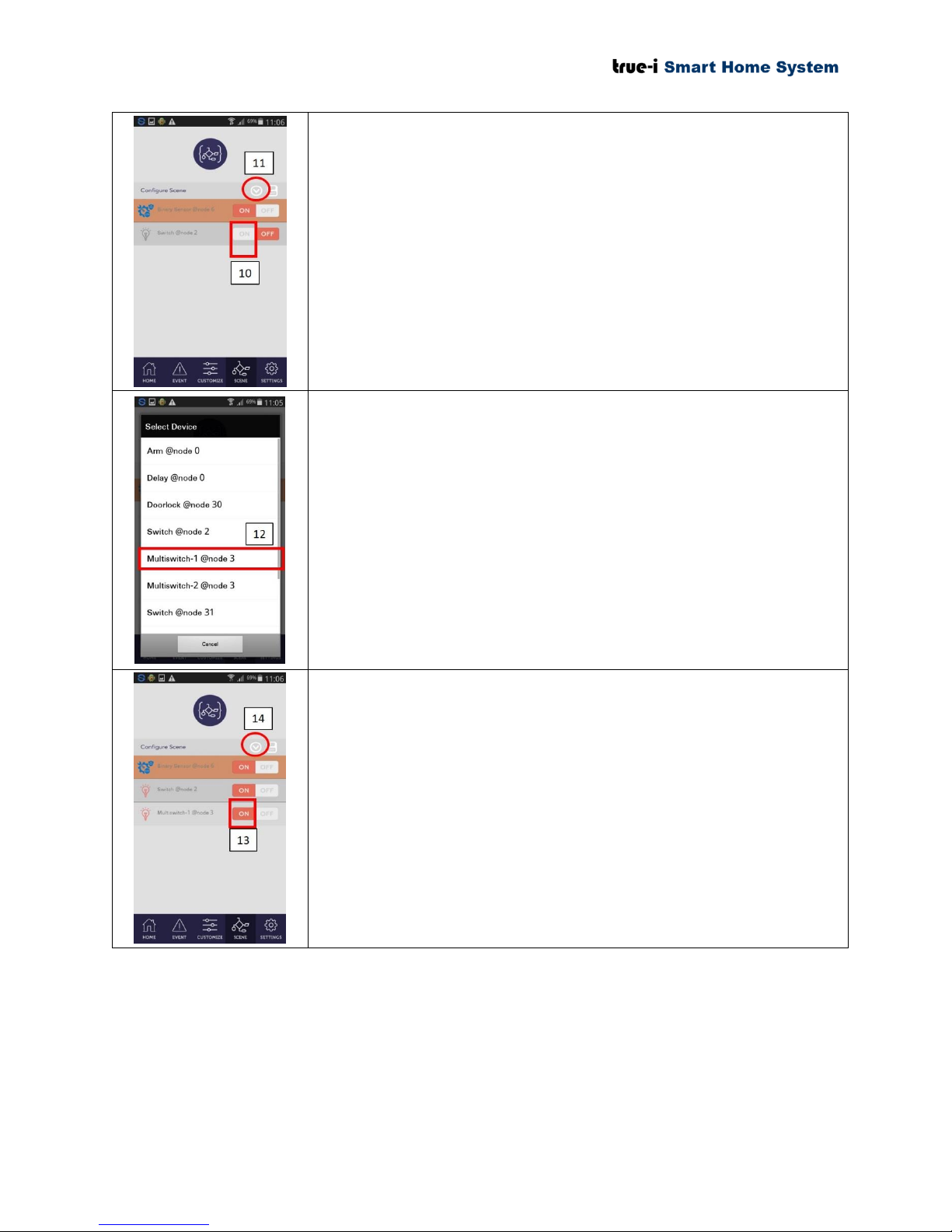
10) As a default add in, the “Switch” is in “OFF” position.
According to the example scenario, the Switch should be in
“ON” position.
11) Click the button to choose for the third sequence to follow.
12) In this scenario, “Multiswitch-1 @ node 3” will be chosen.
The user can choose any node for the desired option.
13) Click the chosen “Multiswitch-1 @ node 3” in “ON” position.
14) Click the button to choose for the fourth sequence to follow.
Page 30 of 37
Page 34
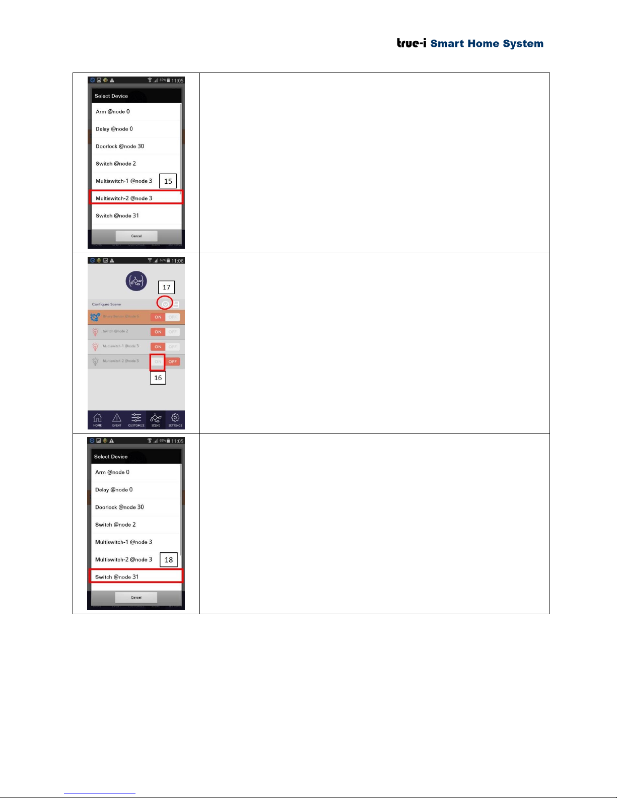
15) In this scenario, “Multiswitch-2 @ node 3” will be chosen.
The user can choose any node for the desired option.
16) Click the chosen “Multiswitch-2 @ node 3” in “ON” position.
17) Click the button to choose for the fifth sequence to follow.
18) In this scenario, “Switch @ node 31” will be chosen for the
fifth sequence. The user can choose any node for the desired
option.
Page 31 of 37
Page 35
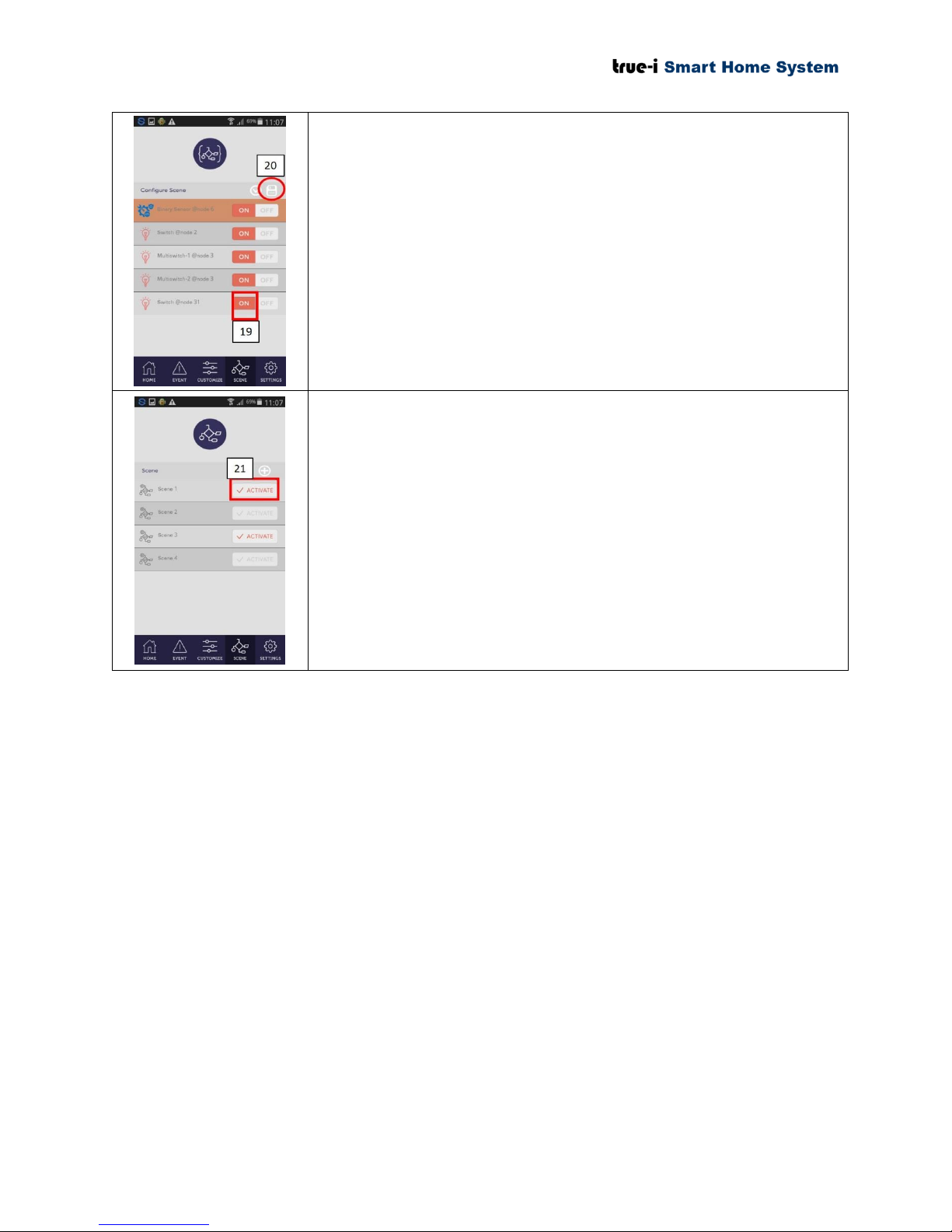
19) Click the chosen “Switch @ node 31” in “ON” position
according to the example.
20) Click “Save” icon for saving the conditional statement set by
the user.
21) The user has to click “ACTIVATE” for the “Scene” that the
user has just created for the conditional sequence to follow.
This example shows that when the door is opened (i.e.; when
the door contact sensor is triggered in open position), the four
lights will be switched “ON”.
The user can create the desired conditional sequence to follow
depending on the devices the user has installed at home or office.
If the user does not want the particular configuration of “Scene”,
the user can click “ACTIVATE”. If the button is NOT
highlighted in orange color, the conditional sequence will not
work.
Page 32 of 37
Page 36
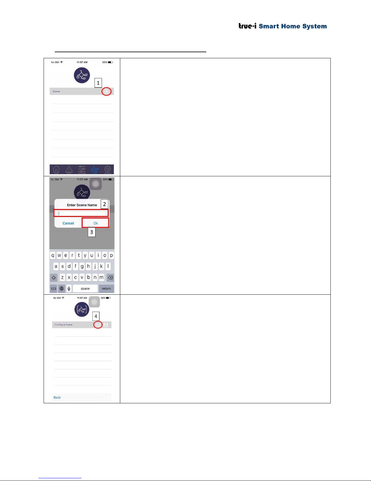
7.2 Configuration in Apple iOS mobile application
“Scene” page is mainly for allowing the users to create simple
conditional statements. This option is also known as IFTTT (“If This
Then That”) option.
21) Click “+” sign, for new “Scene” configuration.
22) There will be a pop up box to enter new “Scene” Name.
Please type the desired name for your “Scene” configuration.
23) Click “OK” after typing the name.
24) Click the button to choose for creating first (main) condition.
Page 33 of 37
Page 37
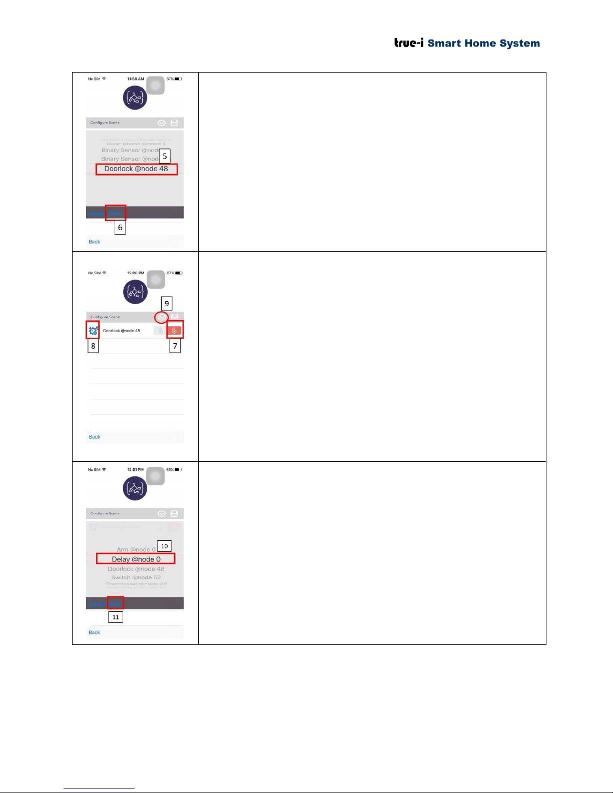
In this scenario, if the door lock is triggered (door is unlocked), the
smart plug will be “ON” after 5 seconds delay.
25) Scroll and choose “Doorlock @ node 48” which is door
contact sensor in this scenario.
26) Click “Done” button after selection.
27) Click “unlock” icon for opening the door. If the user is
triggering for closing position of the door, the user has to
choose “lock” icon.
28) You will see the first (main) triggering option. Please tap the
icon to change the conditional statements on when it should
follow the conditional sequence set by the user.
Blue (as shown in the picture): the condition will be
triggered both in “ARM” and “UN-ARM” mode.
Orange: the condition will be triggered only in
“ARM” mode.
Grey: the condition will be triggered only in “UN-
ARM” mode.
29) Click the button to choose for the second sequence to follow
(e.g.; after opening the door, the light switch will be turned
“ON”).
30) In this scenario, “Delay @ node 0” will be chosen. The user
can choose any node for the desired option.
31) Click “Done” button after selection.
Arm: To put “ARM” to enable “Arm Home” mode.
Under Arm Home mode, the user will get notifications
when motion is detected by the gateway camera or when
the sensor is being triggered depending on the user predefined option.
Delay: To put delay for one sequence after another. The
maximum delay duration the user can set is 10 seconds.
Please ensure that the sequence should not be conflict
with each other from one “Scene” to another “Scene”.
Page 34 of 37
Page 38
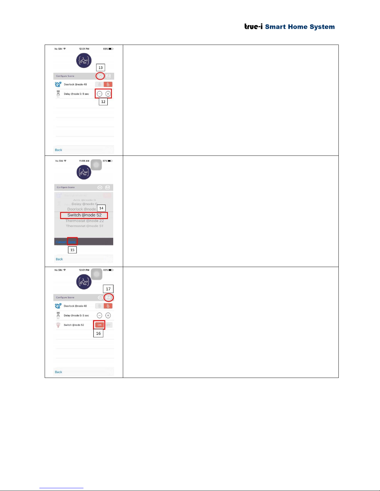
32) The user can put delay up to 10 seconds.
33) Click the button to choose for the third sequence to follow
(e.g.; after unlocking the door, the smart plug will be “ON”).
34) In this scenario, “Switch @ node 52” will be chosen for the
third sequence. The user can choose any node for the desired
option.
35) Click “Done” button after selection.
36) Click the chosen “Switch @ node 52” in “ON” position
according to the example.
37) Click “Save” icon for saving the conditional statement set by
the user.
Page 35 of 37
Page 39
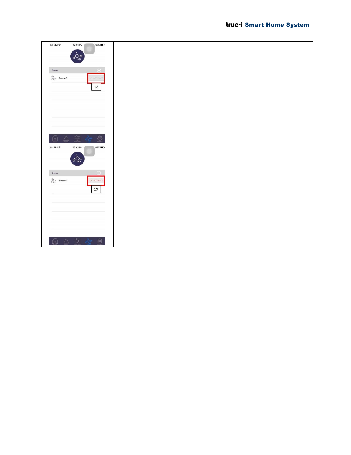
38) As a default, this button will be grey off and the conditional
statement will not be activated until the user press
“ACTIVATE” button.
39) The user has to click “ACTIVATE” for the “Scene” that the
user has just created for the conditional sequence to follow.
This example shows that when the door is unlocked, the smart
plug will be switched “ON” after 5 seconds delay.
The user can create the desired conditional sequence to follow
depending on the devices the user has installed at home or office.
If the user does not want the particular configuration of “Scene”,
the user can click “ACTIVATE”. If the button is NOT
highlighted in orange color, the conditional sequence will not
work.
Page 36 of 37
Page 40
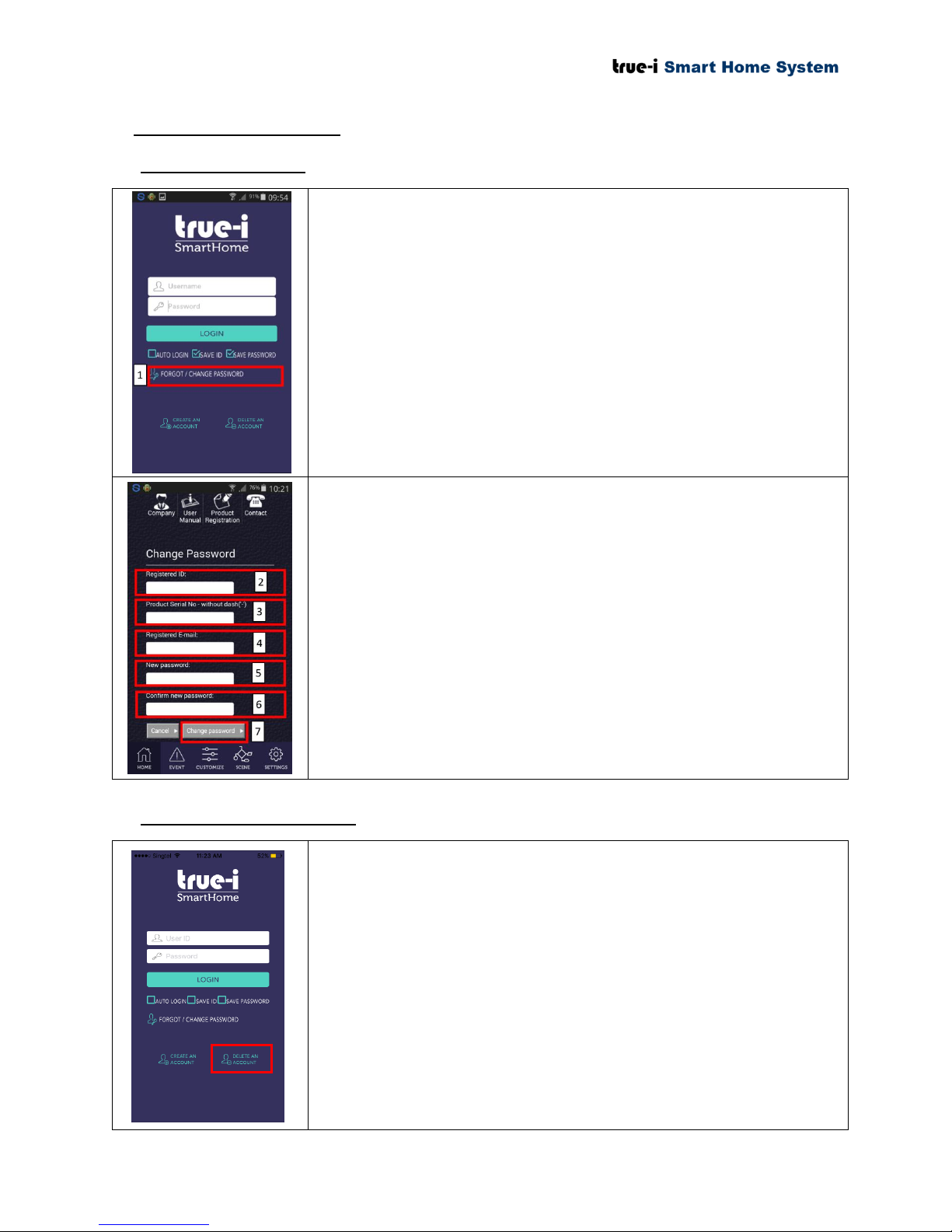
8. Manging user account
1) Click “FORGOT/ CHANGE PASSWORD” if the user forgot
the password.
2) Type “Registered ID” that you have use it before.
3) Type Gateway Serial No. (without dash “-”)
4) Type “Registered email” that the user have used to register for
gateway.
5) Key in the new password.
6) Key in the new password again for confirmation.
7) Click “Change password”.
Changing password will take an immediate effect. Please take
note that no notification will be sent to your email.
* Note: If forget user ID, contact Hanman International
Pte Ltd at (+65)6564-4704.
1. Click “DELETE ACCOUNT” for deactivating the account. It
will lead to the webpage to delete user account. Please fill in
accordingly.
Before deleting the account, please ensure the current
registered user ID, the gateway serial number, email address
that were used to register the gateway and password, are with
you.
After deleting the account, the user will have to re-register the
account by following steps in Section 2 “Creating an account
and registration of serial number” of this user manual.
* Note: If forget user ID, contact Hanman International
Pte Ltd at (+65)6564-4704.
8.1 Changing password
8.2 Deactivating user account
Page 37 of 37
 Loading...