

Trueheat TH36, TH36G, TH36MG, TH36DG, TH36MGF Installation Manual
...
INSTALLATION
MANUAL
OPERATING
AND
MAINTENANCE
INSTRUCTIONS
TH28
/
TH36
/
Ttt*2
For
the
Trueheat®
UL
Listed
Factory-Built
Fireplace
Models
TH36.TH36G,
TH36MG,
TH36MGF,
TH36D,
TH36DG,
TH36DF,
TH36DGF,
TH28,
TH28G,
TH28MG,
TH28MGF,
TH28D,
TH28DG,
TH28DGF,
TH42,
TH42G,
TH42F,
and
TH42GF.*
Congratulations!
You
have just purchased a quality,ULListed Trueheat® Fireplace engineered for safety'
and
durability.
Correct
and
proper
installation
of all Trueheat®
fireplacesisthe
most
important
step
in
ensuring
yearsofsafe
and
continuous
use.
You
should
read
these
instructions
from
fronttoback
prior
to
installing
your
fireplace.
Failuretoinstall
your
Trueheat®
fireplaceinaccordance
with
these
instruc
tions
will void
your
Trueheat®
Warranty
and
may
causeapossible
fire
hazard.
Use
onlyULListed
Trueheat®
fireplace
parts
marked
with
the
UL Listing Mark
and
the
Trueheat®
name.
Useofother
manufacturer's
fireplace
parts
with
your
Trueheat®
fireplace
system
will void
the
Trueheat®
Warranty
and
may
cause
a
possible
fire
hazard.
For
proper
operation
of your
Trueheat'
fireplace
system
refer to
the
Trueheat®
Opera
tion
Manual
providedinthe
plastic
bag
around
your
fireplace
firescreens.
If
you
have
any
question
concerning
the
installation
of
your
Trueheat®
fireplace
system
call
512-474-1378.
'Note
reference
to
TH28,
TH36orTH42inthe
textofthese
instructions
referstoall
28,36or42Models
unless
otherwise
specified.
I/1/H/1
WOOD
HEATING
ALLIANCE
UNDERWRITERS
LABORATORIES
ICBO
RESEARCH
REPORT
NO.
3780
LOS
ANGELES
RESEARCH
REPORT
NO.
24321
IISTID
TRUEHEAT-
INCe
HOWARD
SYSTEMS
CORPORATION
P.O.
BOX
6308
AUSTIN,
TX
78762
(512)474^378
HT>~O10\
ISAREGISTERED
TRADEMARK
OF
HOWARD
SYSTEMS
CORPORATION
INSTALLATION
INSTRUCTIONS
Introduction:
Your TRUEHEAT'
Zero
Clearance
Fireplace
System
has
been
designed
and
testedtoprovideasafe
and
energy-efficient
heat
circulating
fireplace
when
installedinaccordance
with
these
installation
instructions.
Incorrect
installations,
modifying
Trueheat'
components,
or
using
parts
madebyanother
manufacturer
will void
the
Trueheat®
Warranty
and
may
cause
a fire
hazard.
Never
use
fireplace
inserts
or
retrofit
your
Trueheat*
fireplace
withawood
stove
and/or
stove
pipe.
Before
you
start
your
installation,
consult
your
state
and
local
building
and
fire
safety
codes
for
factory-built
fireplaces.
Your local building
inspector
may
not
approve
your
installationifthese
codes
are
not
followed. In
addition,
the
National
Building
Code
requires
that
all
fireplaces
be
installedinaccordance
with
NFPA-211.The
National
Fire
Protection
Association
publica
tion
NFPA-211
requires
that
all
Factory-Built
fireplaces
be
installedinaccordance
with
their
installation
instructions.
All Trueheat•
fireplaces
areULListed
for
useinsingle
and
multi-family
dwellings.
The
models
TH28MG, TH28MGF, TH36MG
and
TH36MGF
are
also
UL
Listed
for
useinmobile
homes.
When
installing
those
fireplaces
in
mobile
homes,
refertothe
section,
"Additional
Requirements
For
Mobile
Home
Installations."
IMPORTANT
CONSIDERATIONS
The
Fireplace:
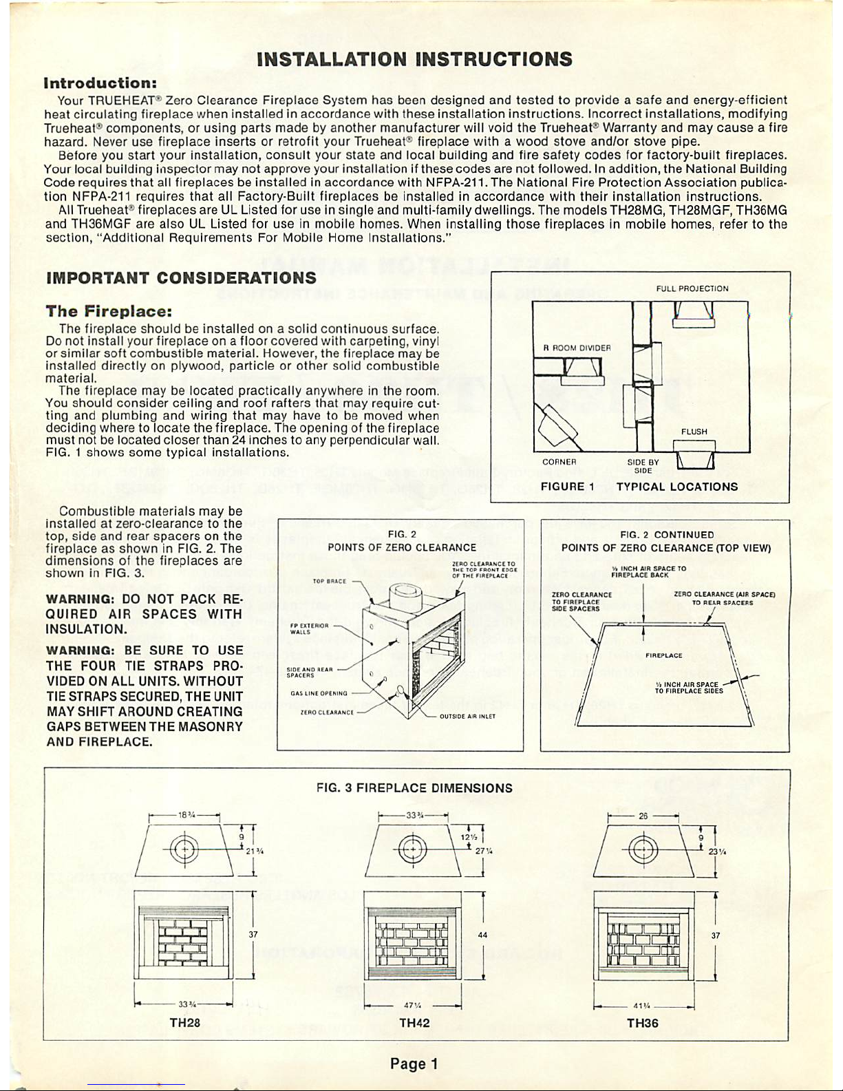
The
fireplace
shouldbeinstalled
onasolid
continuous
surface.
Do
not
install
your
fireplaceona
floor
covered
with
carpeting,
vinyl
or
similar
soft
combustible
material.
However,
the
fireplace
may
be
installed
directlyonplywood,
particleorother
solid
combustible
material.
The
fireplace
maybelocated
practically
anywhereinthe
room.
You
should
consider
ceiling
and
roof
rafters
that
may
require
cut
ting
and
plumbing
and
wiring
that
may
havetobe
moved
when
deciding
wheretolocate
the
fireplace.
The
openingofthe
fireplace
must
notbelocated
closer
than24inchestoany
perpendicular
wall.
FIG.1shows
some
typical
installations.
Combustible
materials
may
be
installed
at
zero-clearance
to
the
top,
side
and
rear
spacers
on
the
fireplace
as
showninFIG.2.The
dimensions
of
the
fireplaces
are
shown
in
FIG.
3.
FIG.
2
POINTS
OF
ZERO
CLEARANCE
WARNING:
DO
NOT
PACK
RE
QUIRED
AIR
SPACES
WITH
INSULATION.
WARNING:
BE
SURE
TO
USE
THE
FOUR
TIE
STRAPS
PRO
VIDED
ON
ALL
UNITS.
WITHOUT
TIE
STRAPS
SECURED,
THE
UNIT
MAY
SHIFT
AROUND
CREATING
GAPS
BETWEEN
THE
MASONRY
AND
FIREPLACE.
CAS
LINE
OPINING
ZIHO
CLEARANCE
ZERO
CLEARANCE
10
THE
TOP'RONE
EDGE
Of
THE
FIREPLACE
OUTSIDE
AIR
INLET
Page
1
R
ROOM
DIVIDER
T3L
FULL
PROJECTION
if
SIDE
BY
SIDE
i
3
TZT
FIGURE
1
TYPICAL
LOCATIONS
FIG.2CONTINUED
POINTSOFZERO
CLEARANCE
(TOP
VIEW)
ZERO
CLEARANCE
TO
FIREPLACE
SIDE
SPACERS
ZERO
CLEARANCE
(AIR
SPACE)
TO
REAR
SPACERS
^L
V,
INCH
AIR
SPACE
TO
FIREPLACE
SIDES
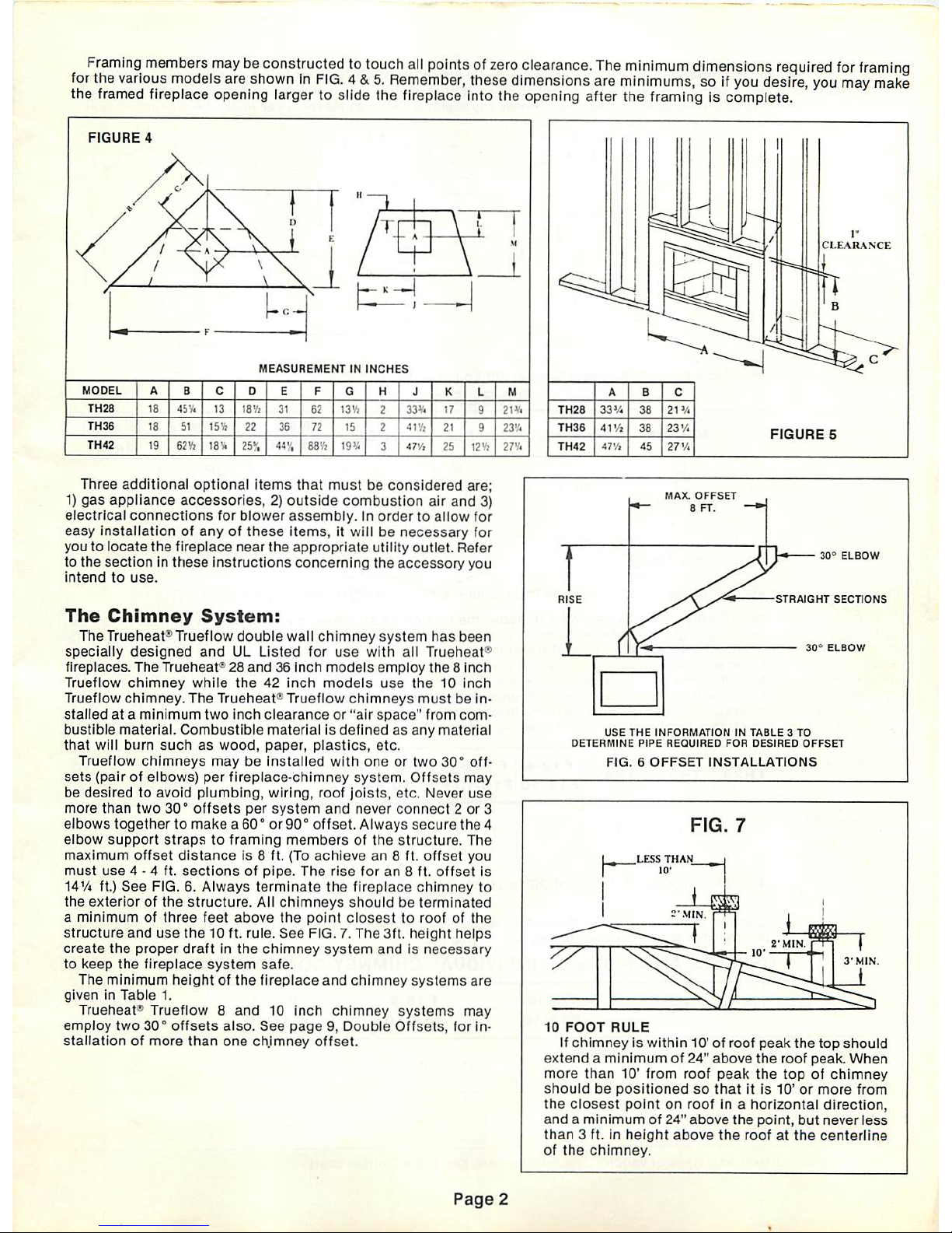
Framing
members
maybeconstructedtotouch
all
pointsofzero
clearance.
The
minimum
dimensions
required
for
framing
for
the
various
models
are
showninFIG.4&5.
Remember,
these
dimensions
are
minimums,
so if
you
desire,
you
may
make
the
framed
fireplace opening larger to slide the fireplace into the opening after the framing is complete.
FIGURE
4
MEASUREMENT
IN
INCHES
MODEL
TH28
18
45
V. 13
18Y)
31
52
13 V, 33V.
17
TH36
15Vz
22
36
72
15
21
TH42
19
62Vi
18 V.
25v,
:<• ,
47
V.
25
12Vz
Three
additional
optional
items
that
mustbeconsidered
are;
1)
gas
appliance
accessories,2)outside
combustion
air
and
3)
electrical
connections
for
blower
assembly.Inordertoallow
for
easy
installationofanyofthese
items,
it willbenecessary
for
you to
locate
the
fireplace
near
the
appropriate
utility
outlet.
Refer
to the
sectioninthese
instructions
concerning
the
accessory
you
intend
to
use.
The
Chimney
System:
The Trueheat* Trueflow
double
wall
chimney
system
has
been
specially
designed
and
UL
Listed
for
use
with
all
Trueheat*
fireplaces.
The
Trueheat*28and36inch
models
employ
the8inch
Trueflow
chimney
while
the
42
inch
models
use
the
10
inch
Trueflow
chimney.
The
Trueheat"
Trueflow
chimneys
mustbein
stalledata
minimum
two
inch
clearanceor"air
space"
from
com
bustible
material.
Combustible
materialisdefinedasany
material
that
will
burn
such
as
wood,
paper,
plastics,
etc.
Trueflow
chimneys
maybeinstalled
with
oneortwo
30°
off
sets
(pair of
elbows)
per
fireplace-chimney
system.
Offsets
may
be
desiredtoavoid
plumbing,
wiring,
roof
joists,
etc.
Never
use
more
than
two
30°
offsets
per
system
and
never
connect2or
3
elbows
togethertomakea60°or90°
offset.
Always
secure
the
4
elbow
support
strapstoframing
membersofthe
structure.
The
maximum
offset
distance
is 8 ft. (To
achievean8 ft.
offset
you
must
use
4 - 4 ft.
sections
of
pipe.
The
rise
foran8 ft.
offset
is
14Vi ft.)
See
FIG. 6.
Always
terminate
the
fireplace
chimney
to
the
exteriorofthe
structure.
All
chimneys
shouldbeterminated
a
minimumofthree
feet
above
the
point
closest
to
roofofthe
structure
and
use
the
10 ft. rule.
See
FIG. 7.
The
3ft.
height
helps
create
the
proper
draftinthe
chimney
system
andisnecessary
to
keep
the
fireplace
system
safe.
The
minimum
heightofthe
fireplace
and
chimney
systems
are
giveninTable
1.
Trueheats
Trueflow8and
10
inch
chimney
systems
may
employ
two
30°
offsets
also.
See
page9,Double
Offsets,
for in
stallationofmore
than
one
chimney
offset.
21V.
23V.
;-.••
Page
2
RISE
MAX.
OFFSET
8
FT.
30°
ELBOW
STRAIGHT
SECTIONS
30s
ELBOW
USE
THE
INFORMATION
IN
TABLE3TO
DETERMINE
PIPE
REQUIRED
FOR
DESIRED
OFFSET
FIG.6OFFSET
INSTALLATIONS
FIG.
7
10
FOOT
RULE
If
chimney
is within 10' of roof
peak
the
top
should
extendaminimum
of 24"
above
the
roof
peak.
When
more
than
10'
from
roof
peak
the
topofchimney
should
be
positioned
so
thatitis
10'ormore
from
the
closest
point
on
roof
in a
horizontal
direction,
andaminimumof24"
above
the
point,
but
never
less
than
3 ft. in
height
above
the
roofatthe
centerline
of
the
chimney.
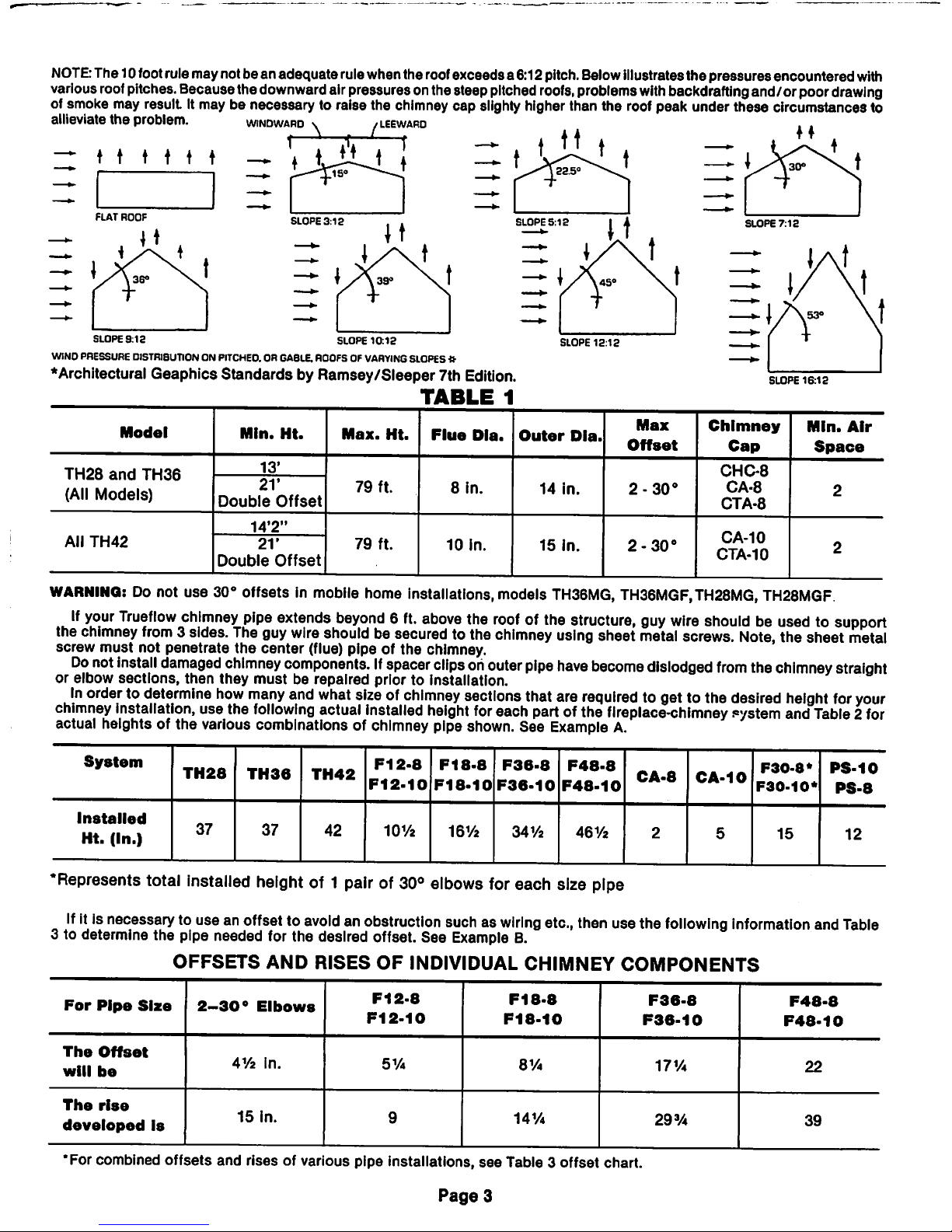
NOTE:
The10footrulemaynotbean adequaterulewhenthe roofexceedsa 6:12pitch.Belowillustratesthe pressures encountered
with
various
roof
pitches.
Becausethe
downward
airpressuresonthesteep
pitched
roofs,
problems
with
backdrafting
and/or poor
drawing
of smoke may result It may be necessary to raise the chimney
cap
slighty higher than the roof peak under these circumstances to
allieviate the problem.
windward
\ /leewaro
A.
1
r
ZZ♦t t t i i — t
Liij
FLAT
ROOF
i36°
SLOPE
9:12
SLOPE
10:12
WIND PRESSURE DISTRIBUTION ON PITCHE0.OR GABLE.ROOFSOFVARYING SLOPES *
♦Architectural
Geaphics
StandardsbyRamsey/Sleeper
7th Edition.
TABLE
1
SLOPE
16:12
Model
Mln.
Ht.
Max.
Ht.
Flue
Dla.
Outer
Dia.
Max
Offset
Chimney
Cap
Min.
Air
Space
TH28
and
TH36
(All
Models)
13'
79
ft.
8
in.
14
in.
2-30°
CHC-8
CA-8
CTA-8
21'
Double
Offset
2
14'2"
79
ft.
10
in.
15
in.
2-30°
CA-10
CTA-10
All
TH42
21'
Double
Offset
2
WARNING:Donot use 30° offsets in mobile home installations,models
TH36MG,
TH36MGF.TH28MG,
TH28MGF
If
your
Trueflow
chimney
pipe
extends
beyond6ft.
above
the
roofofthe
structure,
guy
wire
shouldbeusedtosupport
the
chimney
from
3 sides.
The
guy
wire
should
be secured tothe
chimney
using
sheet
metal
screws.
Note,
the sheet
metal
screw
must
not penetrate
the
center
(flue) pipe of the chimney.
Do
not
install
damaged
chimney
components.Ifspacer
clipsohouter
pipe
have
become
dislodged
from
the
chimney
straight
or elbow sections, then they
must
be repaired prior to installation.
In
ordertodetermine
how
many
and
what
sizeofchimney
sections
that
are
required
togettothe
desired
height
for
your
chimney
installation,
usethe
following
actual
installed
height
for
each
part
ofthe
fireplace-chimney
eystem
and
Table2for
actual heights of the variouscombinations of chimney pipe shown. See
Example
A.
System
Installed
Ht.
(In.)
TH28
37
TH36
37
TH42
42
F12-8
F12-10
10V2
F18-8
F18-10
16Y2
F36-8
F36-10
341/2
F48-8
F48-10
461/2
CA-8
CA-10
F30-8*
F30-10*
15
PS-10
PS-8
12
•Represents
total
installed
height
of 1
pairof30°
elbows
for
each size
pipe
Ifitis
necessary
tousean
offsettoavoidanobstruction
suchaswiring
etc.,
then
usethe
following
information
and
Table
3 to determine the pipe needed for the desired offset. See
Example
B.
OFFSETS
AND
RISES
OF
INDIVIDUAL CHIMNEY
COMPONENTS
For
Pipe
Size
2-30°
Elbows
F12-8
F12-10
F18-8
F18-10
F36-8
F36-10
F48-8
F48-10
The
Offset
will
be
41/2
in.
51/4
8V4
17V4
22
The
rise
developed
is
15
in.
9
14V4
29%
39
•For combined
offsets
and
rises of various pipe installations,
see
Table 3
offset
chart.
Page
3
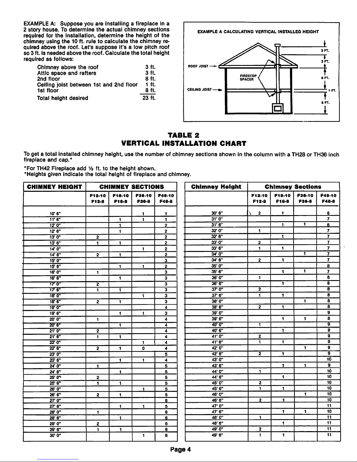
EXAMPLEA:
Suppose
you
are
installingafireplace
in a
2
story
house.Todetermine
the
actual
chimney
sections
required
for
the
installation,
determine
the
heightofthe
chimney
using
the
10 ft.
ruletocalculate
the
chimney
re
quired
above
the
roof.
Let's
suppose
it's
a low
pitch
roof
so
3 ft. is
needed
above
the
roof.
Calculate
the
total
height
requiredasfollows:
Chimney
above
the
roof
3
ft.
Attic
space
and
rafters
3
ft.
2nd
floor
8
ft.
Celling
joist
between
1st
and
2nd
floor
1
ft.
1st
floor
8
ft.
Total
height
desired
23
ft.
EXAMPLEACALCULATING
VERTICAL
INSTALLEO
HEIGHT
^i^b-w
I-"
*
^
3
FT.
^
3
FT.
CEILING
JOIST
».
/
FIRESTOP
/
SPACER V
t
8
FT.
1
\?
'—
t
a
ft.
*
TABLE
2
VERTICAL
INSTALLATION
CHART
To
getatotal
installed
chimney
height,
use
the
numberofchimney
sections
showninthe
column
with
a TH28orTH36
inch
fireplace
and
cap.*
*For
TH42
Fireplace
add
Vt ft.tothe
height
shown.
•Heights
given
indicate
the
total
heightoffireplace
and
chimney.
CHIMNEY
HEIGHT
CHIMNEY
SECTIONS
F12-10
F12-B
P18-10
F18-8
F38-10
P36-8
F48-10
F48-8
10'
6"
1 1
ire-
1 1
12'
0"
2
12"
6"
2
13'
0"
2 2
13'
6"
1
2
14"
0"
1 2
14"
6"
2
2
15'0"
3
15'
6"
1 2
16'
0"
1
3
16'
6"
3
17'0"
2
3
ire-
1
3
18'0"
1 3
18'6"
2
3
19'
0"
4
19"
6"
1 3
20'
0"
1
4
20'
6"
4
2V
0"
2 4
21'
6"
1
4
22'0"
1 4
22'6"
2
0 4
23"
0"
5
23'6"
1
4
24*0"
1
5
24'6"
5
25'(P
2
5
25'
6"
1 5
26'0"
1 S
26'6"
2
5
27'0"
6
27'
6"
1 S
28'
0"
1
6
28'6"
6
29'0"
2
6
29'6"
1
6
30'0"
1 6
Chimney
Height
Chimney
Sections
F12-10
F12-S
F18-10
F18-8
F36-10
F36-8
F48-10
F48-8
30'
6"
\ 2
6
3V
0"
7
31'
6"
1
6
32'
0"
1
32'
6"
33'0"
2
33'6"
1
34'
0"
1
34'
6"
2
35'
0"
8
35'6"
1
7
36'0"
1
8
36'6"
8
37*
0"
2
8
37'
6"
1
8
38'0"
1
8
38'6"
2
8
39'
0"
9
39*
6"
1
8
40'
0"
1
9
40'
6"
9
41'
0"
2
9
41•6"
1
9
42*
0"
1
9
42'
6"
2
9
43'0"
10
43'6"
1
9
44'0"
1
10
44'6"
10
45'0"
2
10
45'
6"
1
10
46'
0"
1
10
46'
6"
2
10
47'
0"
11
47'
6"
1
10
48'
0"
1
11
48'
6"
11
49"
0"
2
11
49'
6"
1
11
Page
4

TABLE
3
OFFSET
CHART
CHIMNEY
SECTIONS
REQUIRED
Offset
Desired
(In.)
2-30°
Elbows
F12-8
F12-10
F18-8
F18-10
F36-8
F36-10
F48-8
F48-10
Rise
Developed
4V2
1
Dair
15
9V«
1
Dair
1
24
12»/4
1
pair
29
V*
15
1
Dair
2
33
18
1
oair
1
38
V*
21V4
1
oair
1
39
23
V*
1
oair
2
47V4
261/a
1
pair
1
54
30
1
pair
1
59
31V4
1
pair
1
63
34J/4
1
pair
68V*
37
1
pair
2
72
40
1
pair
1
771/4
43V4
1
pair
1
83»/4
451/4
1
pair
2
86V4
48V2
1
pair
2
93
52
1
pair
1
1
98
53»/4
1
pair
1
2
102
56V4
1
Dair
2
107V4
59
1
Dair
2
2
111
62
1
oair
1
2
1161/4
65V4
1
Dair
1
2
122
3/4
67V4
1
pair
2
2
125V4
701/2
1
oair
3
132
74
1
oair
1
2
136V2
75
V*
1
pair
1
3
141
78V4
1
pair
3
146V4
Next look on the Vertical Installation ChartTable 2 to determine the piecesof pipe required forthe desired height. A 23 ft. in
stallation requires 5 sections of
F48-8
chimney pipe, as shown onTable 2,a fireplace and chimney cap. Ifyou were installing a
TH42 fireplace,
you
would
only
need
the
pipe required for a 22 ft. 6 inch installation
because
TH42 is 6
inches
taller
than
a
TH36 orTH28soyou
subtract6inches
from
the
desired height. From
the
Vertical Installation Chart, a 22 ft. 6 in. installation re
quires
two
F12-8,
one
F18-8
and
four F48-8
chimney
sections.
EXAMPLEB:Let's say you are installing the fireplace in your family room. Directlyabove the place where you would like to in
stall
the
fireplace is a bedroom. Therefore you
wanttooffset
the
chimney
to avoid
the
room. Inordertocalculate
the
distance
required, measure from the center of
the
fireplace to the back edge of the obstruction. Add to that distance 9 in.
The
number
you
have
calculatedisthe
center-to-center
offset
desired.
SEE
EXAMPLE B FIG.
The
measurement
from
the
centerofthe
fireplace
chimney
openingtothe
rearofthe
house
is 12 in.
The
calculated
center-to-center
offset
wouldbe21 in.Todetermine
the chimney
components
required to obtain a 21 in.
offset
refer to Table 3. FromTable 3 you can
see
the
closest
offset
TO21 is
21V*.
So the chimney sections required areone pairof 30° elbows (offsets), and one
F36-8
chimney section. The risedeveloped
over a 21% in.
offset
is 39 in. Therefore, to determine what otherchimney
sections
are required to obtain
the
desired installed
height, you simply subtract 39 in. from the height desired and referto Table 2 for the necessary chimney components.
Page
5
 Loading...