

Trueheat Salamander S86 Installation, Operation And Service Manual
INSTALLATION, OPERATION
AND SERVICE MANUAL
WARNINGS
SALAMANDER
S86
IMPROPER INSTALLATION, ADJUSTMENT,
ALTERATION, SERVICE OR MAINTENANCE CAN
CAUSE INJURY OR DEATH. THE INSTRUCTION
MANUAL MUST BE READ CAREFULLY BEFORE
INSTALLING, OPERATING OR SERVICING THIS
EQUIPMENT
TO BE INSTALLED ONLY BY AN AUTHORISED PERSON
IN ACCORDANCE WITH AS 5601, LOCAL AUTHORITY,
GAS, ELECTRICITY , ANY APPLICABLE ST ATUTORY
REGULA TIONS AND MANUF ACTURER
REQUIREMENTS.
Salamander Manual Page 1 Revision: 13 Sep 07
OPERATOR MANUAL S86 130907.doc
THIS EQUIPMENT IS DESIGNED FOR COMMERCIAL
CATERING PURPOSES AND WILL GENERATE
SIGNIFICANT HEAT. HOT SURFACES WILL CAUSE
BURNS. A HAZARD AND RISK ASSESSMENT MUST BE
UNDERTAKEN BY OWNERS AND ALL OPERATORS
MADE AWARE OF THESE.
DO NOT STORE OR USE FLAMMABLE LIQUIDS NEAR
THIS APPLIANCE.
DO NOT SPRAY AEROSOLS NEAR THIS APPLIANCE
WHILE IT IS IN OPERATION.
INSTALLATION CLEARANCES AS SPECIFIED MUST BE
OBSERVED.
IF YOU SMELL GAS, TURN THE UNIT OFF AND THE
MAIN GAS SUPPLY VALVE TO THE UNIT. CONTACT
YOUR GAS SUPPLIER OR AN AUTHORISED PERSON.
BEFORE TURNING ON THE MAIN GAS SUPPLY, CHECK
THE UNIT TO BE CERTAIN THAT ALL THE VALVES ARE
IN THE “OFF” POSITION.
PLEASE KEEP THIS MANUAL FOR FUTURE
REFERENCE AND REFERENCE BY ALL OPERATORS.
Salamander Manual Page 2 Revision: 13 Sep 07
OPERATOR MANUAL S86 130907.doc

CONGRATULATIONS
Comcater thanks you for choosing this product and welcomes you to the
ever-growing Comcater customer circle. This product has been specifically
designed by Comcater to meet a wide rage of applications and represents the
best quality and highest value equipment.
Please read the instruction manual carefully to ensure the safe and reliable
operation and performance of your equipment.
Should you ever require service, you will be supported by Comcater’s trained
and qualified service network – the largest available.
Comcater assures you of every support and wishes you every business
success.
Michael Wood
Managing Director
Comcater
Salamander Manual Page 3 Revision: 13 Sep 07
OPERATOR MANUAL S86 130907.doc

TABLE OF CONTENTS
INTRODUCTION .............................................................................................5
GENERAL.................................................................................................5
WARRANTY .............................................................................................5
GENERAL INFORMATION .............................................................................6
INSPECTION............................................................................................6
OPERATOR MANUAL ..............................................................................6
INSTALLATION.........................................................................................6
GAS CONNECTION .................................................................................6
GAS PRESSURE .....................................................................................6
COMMISSIONING....................................................................................6
SPECIFICATIONS...........................................................................................7
INSTALLATION.........................................................................................7
GAS SUPPLY PRESSURE.......................................................................9
NOMINAL GAS CONSUMPTION .............................................................9
TEST POINT PRESSURE........................................................................9
VENTILATION AND AIR SUPPLY.............................................................9
GENERAL SPECIFICATIONS ................................................................10
OPERATING INSTRUCTIONS......................................................................11
LIGHTING INSTRUCTIONS ................................................................... 11
SALAMANDER BURNERS.....................................................................12
SALAMANDER BURNER IGNITION ......................................................12
OPERATOR MAINTENANCE .......................................................................15
CLEANING STAINLESS STEEL.............................................................16
SERVICE.......................................................................................................17
RECOMMENDED SERVICE ..................................................................17
SERVICE INFORMATION ......................................................................17
BURNER ADJUSTMENTS .....................................................................18
CONVERSION INSTRUCTIONS............................................................19
SPARE PARTS .......................................................................................20
TROUBLE SHOOTING .................................................................................21
ALL BURNERS.......................................................................................21
SALAMANDER – MAJOR PARTS IDENTIFICATION ..................................22
SALAMANDER – EXPLODED VIEWS AND
BILL OF MATERIALS ...................................................................................25
DRA WINGS...................................................................................................27
Salamander Manual Page 4 Revision: 13 Sep 07
OPERATOR MANUAL S86 130907.doc

INTRODUCTION
GENERAL
This equipment is designed for commercial catering purposes and
incorporates a wide range of design features to benefit the customer. This
versatility will satisfy a wide range of customer needs.
WARRANTY
This product is warranted for 12 months parts and labour and is subject to the
correct installation, operation, maintenance and care of the equipment.
Warranty does not extend to:
• Damages caused in shipment.
• Damage as a result of incorrect installation.
• Damage as a result of incorrect operation.
• Damages caused by unauthorised service and use of non-original parts.
• Gas supply issues to the equipment.
• Failure resulting from improper maintenance.
• Failure as a result of tampering with, removal of, or changing any preset
control or safety device.
• Service ‘After hours’.
• Conditions as defined in Comcater terms and condition of sale.
For all warranty work, authorized service and genuine and authorized
spare parts, please contact Comcater Service 03 8369 4600.
Please ensure you quote the Model and Serial Number of the unit. The
Model and Serial Number of the unit is recorded on the sales invoice.
Alternatively, the information is recorded on the front of the unit and on the data
plate located behind the front panel.
Salamander Manual Page 5 Revision: 13 Sep 07
OPERATOR MANUAL S86 130907.doc

GENERAL INFORMATION
INSPECTION
Please inspect the unit on receipt. If the unit is damaged, contact the carrier
immediately and file a damage claim with them. Save all packing materials
when filing a claim. Freight damage claims are the responsibility of the
purchaser and are not covered under warranty.
OPERATOR MANUAL
This manual contains important information for your safety and the
installation, operation, maintenance and service of this equipment.
Please read the manual carefully and ensure all operators of the
equipment are aware of the contents and safety requirements.
Warning: You must assess all hazards and risks associated with the
operation of the equipment in your environment and advise all operators
of these.
INSTALLATION
This equipment must be installed by an authorized person in accordance
with AS 5601, local authority, gas, electricity, any applicable statutory
regulations and manufacturer requirements.
GAS CONNECTION
The appliance must be connected by an authorized person to the gas type
specified on the unit. The gas type is shown adjacent to the rear gas
connection point on the back panel and on the data plate. Connect to and use
only the correct type of gas.
GAS PRESSURE
The authorized person installing this equipment must ensure that the gas
operating pressure is the same as shown on the rating plate, the test point
pressure is correct (refer page 9) and that there is sufficient gas volume.
COMMISSIONING
The authorized person installing this equipment must commission the
equipment in accordance with AS 5601 - gas leakage, operational checking,
adjustments and instructing the owner on use of the equipment are prescribed
requirements.
Salamander Manual Page 6 Revision: 13 Sep 07
OPERATOR MANUAL S86 130907.doc
SPECIFICATIONS
INSTALLATION
THIS EQUIPMENT MUST BE INSTALLED BY AN
AUTHORIZED PERSON IN ACCORDANCE WITH AS 5601,
LOCAL AUTHORITY, GAS, ELECTRICITY, ANY APPLICABLE
STATUTORY REGULATIONS AND MANUFACTURER
REQUIREMENTS.
NOTE: INSTALLATION IS THE RESPONSIBILITY OF THE OWNER
Gas Inlet Connection: ½” BSP Female.
Gas Connection Point: The gas connection point is located at the rear of
the unit (300 mm from the right hand side and
45mm above the base of the unit)
Details are shown in the drawing at the rear of this
manual.
Gas Connection: The appliance must be connected by an
authorized person to the gas type specified on the
unit. The gas type is shown adjacent to the gas
connection point and on the data plate. Connect
to and use only the correct type of gas.
The authorized person installing this equipment
must comply with AS 5601 requirements.
Prescribed requirements include, commission the
equipment, gas leakage testing, operational
checking and adjustments.
All units are tested and adjusted at the factory; however, burners and pilots
must be checked at the installed location and adjusted if necessary.
Salamander Manual Page 7 Revision: 13 Sep 07
OPERATOR MANUAL S86 130907.doc
Data Plate: The data plate is located behind the front panel.
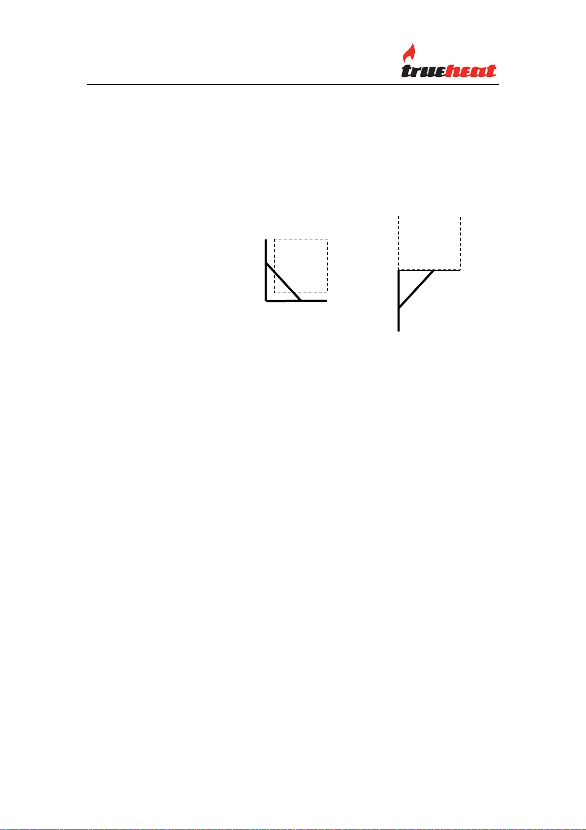
Installation: The Salamander is provided with two mounting
brackets. The brackets may be fitted in two ways
as follows:
Select a suitable location and fix the mounting
brackets in position (Refer ‘Installation Clearances’
below). The brackets must be securely mounted.
Mount the Salamander to the brackets by inserting
the four M10 mounting bolts (supplied) from the
underside of the bracket into the Salamander.
Warning: The Salamander mounting bolt s must
be inserted and secured.
Warning: The Salamander should never be
installed and operated as a counter top unit.
Installation Clearances: The MINIMUM clearances from combustible
surfaces are:
Sides: 300mm (Note: the sides of the Salamander
are removable and adequate clearance must be
provided for safe handling large products.
Rear: 100mm
Adequate clearance must also be provided for
service.
Salamander Manual Page 8 Revision: 13 Sep 07
OPERATOR MANUAL S86 130907.doc
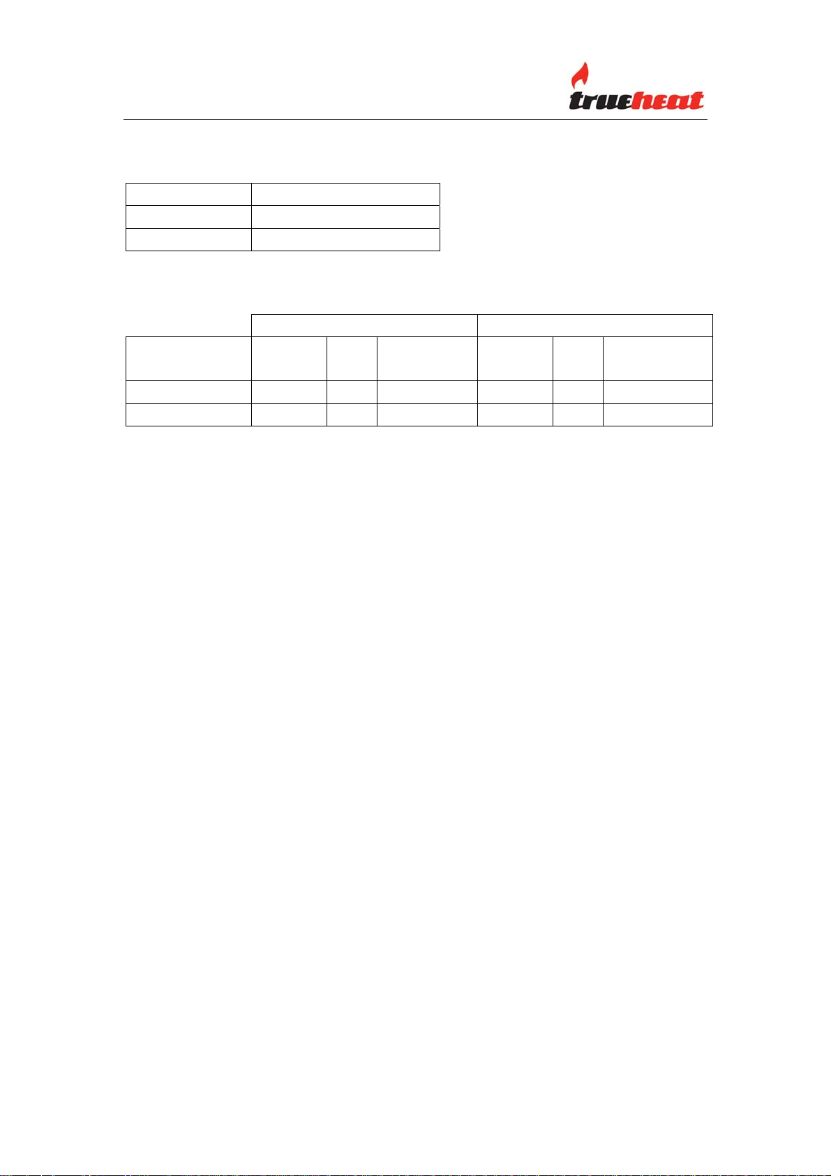
MINIMUM GAS SUPPLY INLET PRESSURE
Gas Type Gas Pressure
Natural Gas 1.13 kPa
LP Gas 2.75 kPa
NOMINAL GAS CONSUMPTION
BURNER
(EACH)
SALAMANDER 1.70mm 14 1.0 kPa 1.00mm 13 2.60 kPa
TOTAL
ORIFICE
NATURAL GAS PROPANE GAS
MJ/h TEST POINT
(mm)
28 26
PRESSURE
ORIFICE
(mm)
MJ/h TEST POINT
PRESSURE
Note: Pressure test point is located on the gas manifold (refer also ‘Test Point
Pressure’ below).
Turndown Setting
Natural Gas 5 turns out from fully in
Propane Gas 3 turns out from fully in
TEST POINT PRESSURE
The gas pressure test point is located on the gas manifold and is accessed by
removing the gas valve control knobs, piezzo igniter leads and the front panel.
The test point pressure is shown in the Nominal Gas Consumption Table
above and is set with the two burners operating at maximum setting.
VENTILA TION AND AIR SUPPL Y
All gas burners and pilots require sufficient air to operate. For optimum
performance and for your safety, it is ESSENTIAL that the equipment, in the
installed position, has the proper air and ventilation and the correct
exhaust/canopy and air balance. The correct installation and compliance with
all regulatory and other requirements is the responsibility of the
purchaser/owner.
Please note that a strong exhaust canopy will create a vacuum if there is
insufficient replacement air. The amount of air exhausted must be replaced by
an equal amount of air.
Airflow to the appliance must not be blocked or restricted (e.g. large objects
should not be placed in front of the appliance).
Salamander Manual Page 9 Revision: 13 Sep 07
OPERATOR MANUAL S86 130907.doc
 Loading...