

Page 1
INSTALLATION AND OPERATION
MANUAL
RANGE SERIES
WARNINGS
IMPROPER INSTALLATION, ADJUSTMENT,
ALTERATION, SERVICE OR MAINTENANCE CAN
CAUSE INJURY OR DEATH. THE INSTRUCTION
MANUAL MUST BE READ CAREFULLY BEFORE
INSTALLING, OPERATING OR SERVICING THIS
EQUIPMENT
TO BE INSTALLED ONLY BY AN AUTHORISED PERSON
IN ACCORDANCE WITH AS 5601, LOCAL AUTHORITY,
GAS, ELECTRICITY , ANY APPLICABLE ST ATUTORY
REGULA TIONS AND MANUFACTURER
REQUIREMENTS.
Range Manual Page 1 Revision: 13 Sep 07
OPERATOR MANUAL 130907.doc
Page 2
THIS EQUIPMENT IS DESIGNED FOR COMMERCIAL
CATERING PURPOSES AND WILL GENERATE
SIGNIFICANT HEAT. HOT SURFACES WILL CAUSE
BURNS. A HAZARD AND RISK ASSESSMENT MUST BE
UNDERTAKEN BY OWNERS AND ALL OPERATORS
MADE AWARE OF THESE.
DO NOT STORE OR USE FLAMMABLE LIQUIDS NEAR
THIS APPLIANCE.
DO NOT SPRAY AEROSOLS NEAR THIS APPLIANCE
WHILE IT IS IN OPERATION.
INSTALLATION CLEARANCES AS SPECIFIED MUST BE
OBSERVED.
IF YOU SMELL GAS, TURN THE UNIT OFF AND THE
MAIN GAS SUPPLY VALVE TO THE UNIT. CONTACT
YOUR GAS SUPPLIER OR AN AUTHORISED PERSON.
BEFORE TURNING ON THE MAIN GAS SUPPLY, CHECK
THE UNIT TO BE CERTAIN THAT ALL THE VALVES ARE
IN THE “OFF” POSITION.
PLEASE KEEP THIS MANUAL FOR FUTURE
REFERENCE AND REFERENCE BY ALL OPERATORS.
Range Manual Page 2 Revision: 13 Sep 07
OPERATOR MANUAL 130907.doc
Page 3

CONGRATULATIONS
Comcater thanks you for choosing this product and welcomes you to the
ever-growing Comcater customer circle. This product has been specifically
designed by Comcater to meet a wide rage of applications and represents the
best quality and highest value equipment.
Please read the instruction manual carefully to ensure the safe and reliable
operation and performance of your equipment.
Should you ever require service, you will be supported by Comcater’s trained
and qualified service network – the largest available.
Comcater assures you of every support and wishes you every business
success.
Michael Wood
Managing Director
Comcater
Range Manual Page 3 Revision: 13 Sep 07
OPERATOR MANUAL 130907.doc
Page 4

TABLE OF CONTENTS
INTRODUCTION----------------------------------------------------------------------------------------------6
GENERAL ------------------------------------------------------------------------------------------------6
WARRANTY ---------------------------------------------------------------------------------------------6
GENERAL INFORMATION--------------------------------------------------------------------------------7
INSPECTION --------------------------------------------------------------------------------------------7
OPERATOR MANUAL---------------------------------------------------------------------------------7
INSTALLATION------------------------------------------------------------------------------------------7
GAS CONNECTION -----------------------------------------------------------------------------------7
GAS PRESSURE---------------------------------------------------------------------------------------7
COMMISSIONING -------------------------------------------------------------------------------------7
SPECIFICATIONS--------------------------------------------------------------------------------------------8
INSTALLATION------------------------------------------------------------------------------------------8
GAS INPUT INFORMATION----------------------------------------------------------------------- 10
GAS SUPPLY PRESSURE ------------------------------------------------------------------------ 10
NOMINAL GAS CONSUMPTION ----------------------------------------------------------------10
TEST POINT PRESSURE-------------------------------------------------------------------------- 10
VENTILATION & AIR SUPPLY -------------------------------------------------------------------- 11
MODEL OPTIONS------------------------------------------------------------------------------------ 12
GENERAL SPECIFICATIONS--------------------------------------------------------------------- 12
OPERATING INSTRUCTIONS ------------------------------------------------------------------------- 13
LIGHTING INSTRUCTIONS ----------------------------------------------------------------------- 13
OPEN TOP BURNERS------------------------------------------------------------------------------ 14
GRILL BURNER(S) ---------------------------------------------------------------------------------- 15
OVEN BURNER -------------------------------------------------------------------------------------- 16
OPERATOR MAINTENANCE--------------------------------------------------------------------------- 18
SEASONING THE GRILL -------------------------------------------------------------------------- 18
CLEANING STAINLESS STEEL------------------------------------------------------------------ 19
OVEN INTERIOR (Enamel)------------------------------------------------------------------------ 19
OPEN TOP BURNERS------------------------------------------------------------------------------ 19
ENAMELLED TRIVETS----------------------------------------------------------------------------- 20
Range Manual Page 4 Revision: 13 Sep 07
OPERATOR MANUAL 130907.doc
Page 5

TABLE OF CONTENTS (continued)
SERVICE........................................................................................................................21
RECOMMENDED SERVICE ...................................................................................21
SERVICE INFORMATION .......................................................................................21
OPEN AND GRILL BURNER ADJUSTMENTS........................................................ 22
OVEN CONTROL SETTINGS AND ADJUSTMENTS.............................................. 23
CONVERSION INSTRUCTIONS ............................................................................. 25
SPARE PARTS ........................................................................................................26
TROUBLE SHOOTING...................................................................................................27
ALL BURNERS ........................................................................................................ 27
OVEN....................................................................................................................... 28
RANGE OPTIONS.....................................................................................................29-30
MAJOR PARTS IDENTIFICATION............................................................................31-34
EXPLODED VIEWS AND BILL OF MATERIALS......................................................35-45
DRAWINGS ...............................................................................................................46-59
Range Manual Page 5 Revision: 13 Sep 07
OPERATOR MANUAL 130907.doc
Page 6

INTRODUCTION
GENERAL
This equipment is designed for commercial catering purposes and
incorporates a wide range of design features. It is available in various
configurations for open burners, grill sections and oven and as a top only unit.
This versatility will satisfy a wide range of customer needs.
WARRANTY
This product is warranted for 12 months parts and labour and is subject to the
correct installation, operation, maintenance and care of the equipment.
Warranty does not extend to:
• Damages caused in shipment
• Damage as a result of incorrect installation
• Damage as a result of incorrect operation
• Damages caused by unauthorised service and use of non original parts
• Gas supply issues to the equipment
• Failure resulting from improper maintenance
• Failure as a result of tampering with, removal of, or changing any preset
control or safety device
• Service ‘After hours’
• Conditions as defined in Comcater terms and condition of sale
For all warranty work, authorized service and genuine and authorized
spare parts, please contact Comcater Service 03 8369 4600.
Please ensure you quote the Model and Serial Number of the unit. The
Model and Serial Number of the unit is recorded on the sales invoice.
Alternatively:
For ranges with ovens - the information is recorded on the data plate behind
the oven control panel. Please refer to the SPECIFICATION (Installation)
section to access the data plate. Please ensure you locate and replace the
outer oven control knob correctly.
For Top only units – the information is recorded on the data plate located at
the rear of the unit.
Range Manual Page 6 Revision: 13 Sep 07
OPERATOR MANUAL 130907.doc
Page 7

GENERAL INFORMATION
Inspection.
Please inspect the unit on receipt. If the unit is damaged, contact the carrier
immediately and file a damage claim with them. Save all packing materials
when filing a claim. Freight damage claims are the responsibility of the
purchaser and are not covered under warranty.
Operator Manual.
This manual contains important information for your safety and the
installation, operation, maintenance and service of this equipment.
Please read the manual carefully and ensure all operators of the
equipment are aware of the contents and safety requirements. You must
also assess all hazards and risks associated with the operation of the
equipment in your environment and advise all operators of these.
Installation.
This equipment must be installed by an authorized person in accordance
with AS 5601, local authority, gas, electricity, any applicable statutory
regulations and manufacturer requirements.
Gas Connection.
The appliance must be connected by an authorized person to the gas type
specified on the unit. The gas type is shown adjacent to the rear gas
connection point and on the data plate. Connect to and use only the correct
type of gas.
Gas Pressure.
The authorized person installing this equipment must ensure that the gas
operating pressure is the same as shown on the rating plate and that there is
sufficient gas volume.
Commissioning.
The authorized person installing this equipment must commission the
equipment in accordance with AS 5601 - gas leakage, operational checking,
adjustments and instructing the owner on use of the equipment are prescribed
requirements.
Range Manual Page 7 Revision: 13 Sep 07
OPERATOR MANUAL 130907.doc
Page 8

SPECIFICATIONS
INSTALLATION
THIS EQUIPMENT MUST BE INSTALLED BY AN
AUTHORIZED PERSON IN ACCORDANCE WITH AS 5601,
LOCAL AUTHORITY, GAS, ELECTRICITY , ANY APPLICABLE
STATUTORY REGULATIONS AND MANUFACTURER
REQUIREMENTS.
NOTE: INSTALLATION IS THE RESPONSIBILITY OF THE OWNER
Gas Inlet Connection: 3/4” BSP Female.
Gas Connection Point: For Range units, the gas connection point is
located at the rear of the unit (600 mm above the
floor and 85 mm from the right hand side)
For Top only units, the gas connection point is
located at the rear of the unit (85mm above the
base and 85mm from the right hand side)
Details are shown in the drawings at the rear of
this manual.
Gas Connection: The appliance must be connected by an
authorized person to the gas type specified on the
unit. The gas type is shown adjacent to the rear
gas connection point and on the data plate.
Connect to and use only the correct type of
gas.
The authorized person installing this equipment
must comply with AS 5601 requirements.
Prescribed requirements include, commission the
equipment, gas leakage testing, operational
checking and adjustments.
All units are tested and adjusted at the factory; however, burners and pilots
must be checked at the installed location and adjusted if necessary.
Range Manual Page 8 Revision: 13 Sep 07
OPERATOR MANUAL 130907.doc
Page 9
Data Plate: For ranges with ovens, the data plate is located
behind the oven control panel. For Top only units,
the data plate is located at the rear of the unit.
Data Plate Access: To access the data plate on a Range unit:
• turn the oven thermostat control knob to the
OFF position
OFF
• remove the oven thermostat control knob by
gently pulling (a smaller knob remains and
is not to be removed),
• undo the screw at the top of the panel and
open the panel
• carefully remove the lead from the piezzo
igniter and then fully open the panel.
To close the panel, follow the above procedures in
reverse. Ensure the piezzo igniter is re connected.
After re inserting the screw, ensure that the inner
knob is in the OFF position and then align the
outer oven thermostat control knob with the OFF
position and gently push the knob back on.
Clearances Oven Base: When the unit is installed and the legs are
adjusted so that the top of the front rail is 910mm
above the floor, the unit may be installed on a
non-combustible surface (the unit is set at 910mm
ex factory). If the height from the floor to the top of
the front rail is less than 910mm, the unit must be
installed on a fireproof base. Legs on floor
models must not be removed – the space under
the unit is a primary source of air for the oven
burner combustion.
Range Manual Page 9 Revision: 13 Sep 07
OPERATOR MANUAL 130907.doc
Page 10

Installation Clearances: The MINIMUM clearance from combustible
surfaces is 150 mm (Sides and Rear). Adequate
clearance must also be provided for service.
Levelling: Refer also to ‘Clearances Oven Base’ above.
To adjust the legs to level the unit to the floor
and/or to slightly adjust the height of the unit, raise
the front of the unit and adjust the legs (ensure
safe work practices). Similarly, raise the back and
adjust the legs. DO NOT LAY THE UNIT ON ITS
BACK. ENSURE THE UNIT IS LEVEL.
GAS INPUT INFORMATION
MINIMUM GAS SUPPLY INLET PRESSURE
Gas Type Gas Pressure
Natural Gas 1.13 kPa
LP Gas 2.75 kPa
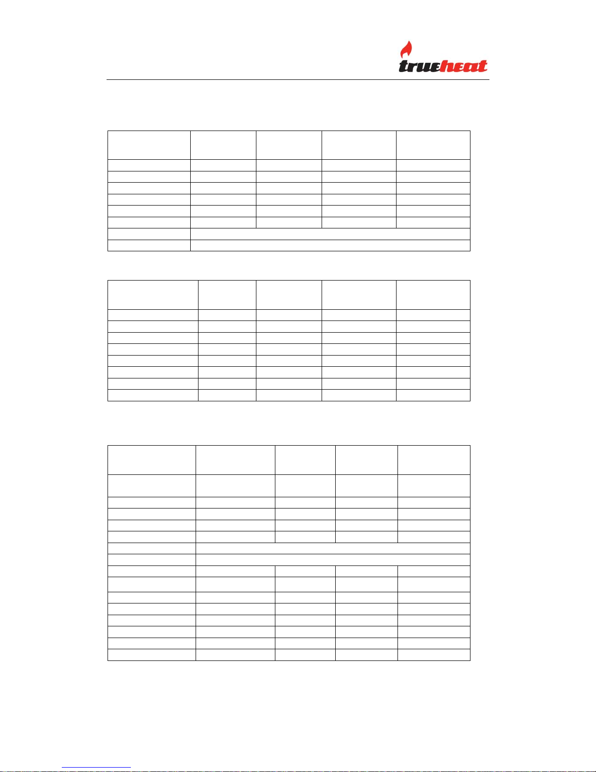
NOMINAL GAS CONSUMPTION
NATURAL GAS PROPANE GAS
BURNER
(EACH)
ORIFICE
(mm)
MJ/h TEST POINT
PRESSURE
ORIFICE
(mm)
MJ/h TEST POINT
PRESSURE
OPEN (Each) 2.30 24 1.0 kPa 1.40 23 2.50 kPa
GRILL (Each) 2.20 22.5 1.0 kPa 1.30 19.5 2.50 kPa
OVEN (Each) 2.60 30 .85 kPa 1.50 26 2.45 kPa
PILOT (Each) .20 .50 1.0 kPa .20 .50 2.50 kPa
Note: Pressure test points are located as follows (refer also ‘Test Point
Pressure’ below);
a. open top and grill burners - gas manifold, and
b. oven burner – located on the EUROSIT 630 Thermostat
TEST POINT PRESSURE
The open top and grill gas pressure test point is located on the gas manifold.
The gas manifold and pressure test point is accessed by removing the gas
valve control knobs and the front panel. The test point pressure is shown in the
Nominal Gas Consumption Table above and is set with two open top
burners operating at maximum setting.
Range Manual Page 10 Revision: 13 Sep 07
OPERATOR MANUAL 130907.doc
Page 11

The oven burner pressure test point is located on the EUROSIT 630
thermostat. To access and make adjustments – refer to the SERVICE section
of this manual. The test point pressure is shown in the Nominal Gas
Consumption Table above and set to the specified pressure AFTER the gas
manifold pressure has been set.
VENTILA TION AND AIR SUPPL Y
All gas burners and pilots require sufficient air to operate. For optimum
performance and for your safety, it is ESSENTIAL that the equipment, in the
installed position, has the proper air and ventilation and the correct
exhaust/canopy and air balance. The correct installation and compliance with
all regulatory and other requirements is the responsibility of the
purchaser/owner.
Please note that a strong exhaust canopy will create a vacuum if there is
insufficient replacement air. The amount of air exhausted must be replaced by
an equal amount of air.
Airflow to the appliance must not be blocked or restricted (e.g. large objects
should not be placed in front of the appliance). The flue must never be covered
or restricted in any way.
Range Manual Page 11 Revision: 13 Sep 07
OPERATOR MANUAL 130907.doc
Page 12
MODEL OPTIONS
RANGE OPTIONS COMPLETE WITH OVEN
Model
Open
Burners
Width of
Grill (mm)
Grill
Position
Oven
R90-6 6 0 Yes
R90-4-30GL 4 300 Left Yes
R90-4-30GR 4 300 Right Yes
R90-2-60GL 2 600 Left Yes
R90-2-60GR 2 600 Right Yes
R90-0-90G 0 900 Yes
R60-4 To be developed
R60-0-60G To be developed
RANGE OPTIONS TOP ONLY
Model
Open
Burners
Width of
Grill (mm)
Grill
Position
Oven
T90-6 6 0 No
T90-4-30GL 4 300 Left No
T90-4-30GR 4 300 Right No
T90-2-60GL 2 600 Left No
T90-2-60GR 2 600 Right No
T90-0-90G 0 900 No
T60-4 4 0 No
T60-0-60G 0 600 No
GENERAL SPECIFICATIONS
OVERALL DIMENSIONS AND WEIGHT
MODEL HEIGHT
(mm)
WIDTH
(mm)
DEPTH
(mm)
WEIGHT
(Kg)
RANGE
COMPLETE
R90-6 1115mm 900mm 803mm 180Kg
R90-0-90G 1115mm 900mm 803mm 174Kg
R90-2-60G 1115mm 900mm 803mm 162Kg
R90-4-30G 1115mm 900mm 803mm 179Kg
R60-4 To be developed
R60-0-60G To be developed
TOP ONLY
T90-6 385mm 900mm 803mm 90Kg
T90-0-90G 385mm 900mm 803mm 84Kg
T90-2-60G 385mm 900mm 803mm 72Kg
T90-4-30G 385mm 900mm 803mm 89Kg
T60-4 385mm 600mm 803mm 60Kg
T60-0-60G 385mm 600mm 803mm 56Kg
Detailed dimensional specifications are shown at the rear of this manual.
Range Manual Page 12 Revision: 13 Sep 07
OPERATOR MANUAL 130907.doc
Page 13
OPERATING INSTRUCTIONS
LIGHTING INSTRUCTIONS
DO NOT OPERATE THE UNIT UNLESS IT HAS BEEN
INST ALLED AND COMMISSIONED BY AN AUTHORIZED
PERSON.
BEFORE TURNING ON THE MAIN GAS SUPPLY, CHECK AND
ENSURE THAT ALL THE VALVES ARE IN THE “OFF”
POSITION.
THIS EQUIPMENT IS DESIGNED FOR COMMERCIAL
CATERING PURPOSES AND WILL GENERATE SIGNIFICANT
HEA T. HOT SURF ACES WILL CAUSE BURNS. A HAZARD AND
RISK ASSESSMENT MUST BE UNDERTAKEN BY OWNERS
AND ALL OPERATORS MADE AWARE OF THESE.
NOTE: Ensure the gas supply to the equipment is turned ON.
NOTE: For your safety, all burners are controlled by a flame failure
sensing device. If the device does not sense a flame, gas
supply to the burner will be cut.
WARNING: When open top burners adjacent to the backgaurd or the side
of a grill plate are operated at high heat and covered by large
cooking vessels (i.e. pots, pans etc), dispersing heat may
cause discolouration and or distortion of the adjacent metal
surface.
Range Manual Page 13 Revision: 13 Sep 07
OPERATOR MANUAL 130907.doc
Page 14

OPEN TOP BURNERS
Open/Grill Burner Control
Pilot Flame Ignition
Starting from the OFF● position, press the control knob and rotate to the
PILOT ★ position.
Press the knob and ignite the pilot flame with a taper - keep the knob fully
depressed for 15 seconds after the pilot lights.
Release the knob and check the pilot flame stays alight. If the pilot flame did
not stay alight, repeat the ignition procedure.
Open Burner Ignition
Slightly depress the control knob and rotate to LEVEL 1 or LEVEL 2.
When the automatic valve senses that the pilot is alight, the gas flow to the
main burner is opened.
Pilot Standby Position
To turn the main burner off and keep the pilot ON, slightly depress the control
knob and rotate to the PILOT ★ position.
Shut Down/Pilot OFF
Slightly depress the control knob and rotate to the OFF ● position.
Range Manual Page 14 Revision: 13 Sep 07
OPERATOR MANUAL 130907.doc
Page 15

NOTE: If the pilot flame were accidentally extinguished, the flame failure safety
device would operate and cut the gas flow to the main burner. It would then be
necessary to re light the pilot by following the above procedure.
GRILL BURNER(S)
NOTE: Ensure the gas supply to the equipment is turned ON
Pilot Flame Ignition
Starting from the OFF ● position, press the control knob and rotate to the
PILOT ★ position.
Press the control knob and then press the piezzo igniter to ignite the pilot flame
– repeat until the pilot ignites (the pilot flame can be viewed through the front
panel). Keep the knob fully depressed for 15 seconds after the pilot lights.
Release the knob and check the pilot flame stays alight. If the pilot flame did
not stay alight, repeat the ignition procedure.
Grill Burner Ignition
Slightly depress the control knob and rotate to the LEVEL 1 or LEVEL 2
position.
When the automatic valve senses that the pilot is alight, the gas flow to the
main burner is opened.
Pilot Standby Position
To turn the main burner off and keep the pilot ON, slightly depress the control
knob and rotate to the PILOT ★ position.
Shut Down/Pilot OFF
Slightly depress the control knob and rotate to the OFF ● position.
NOTE: If the pilot flame were accidentally extinguished, the flame failure safety
device would operate and cut the gas flow to the main burner. It would then be
necessary to re light the pilot by following the above procedure.
Range Manual Page 15 Revision: 13 Sep 07
OPERATOR MANUAL 130907.doc
Page 16
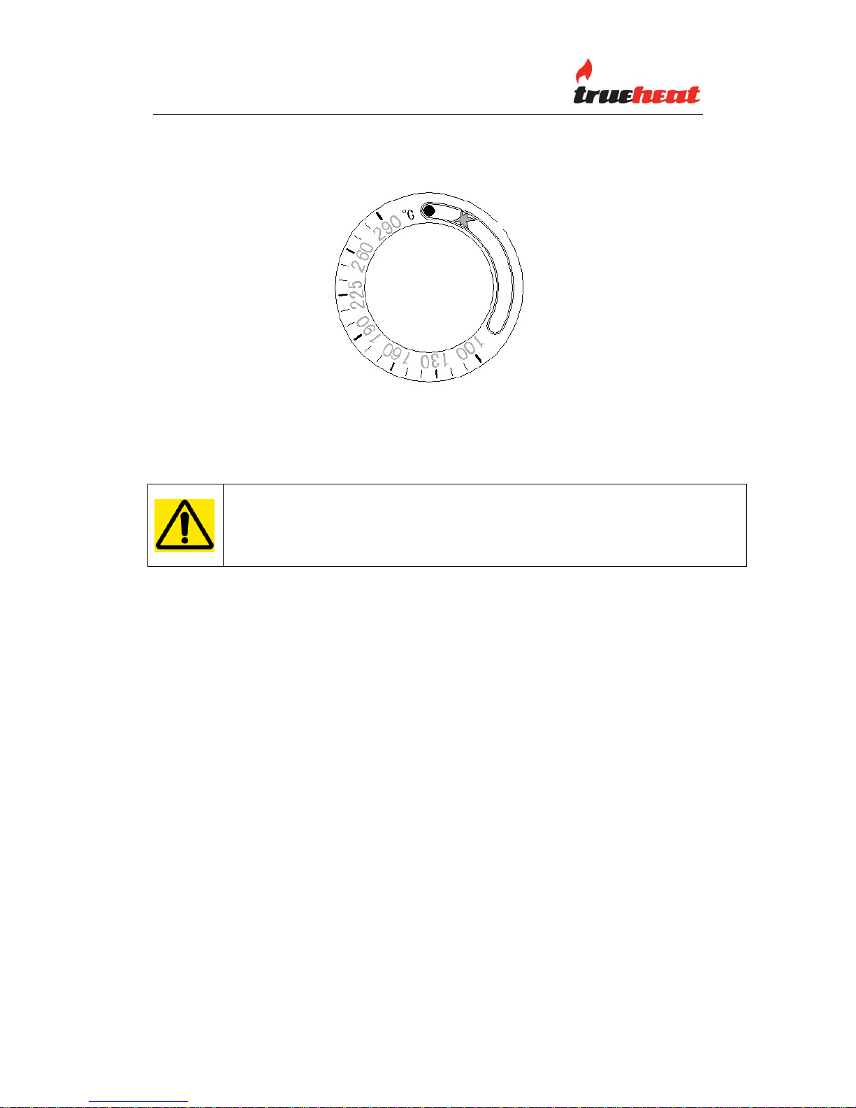
OVEN BURNER
OFF ●
PILOT ★
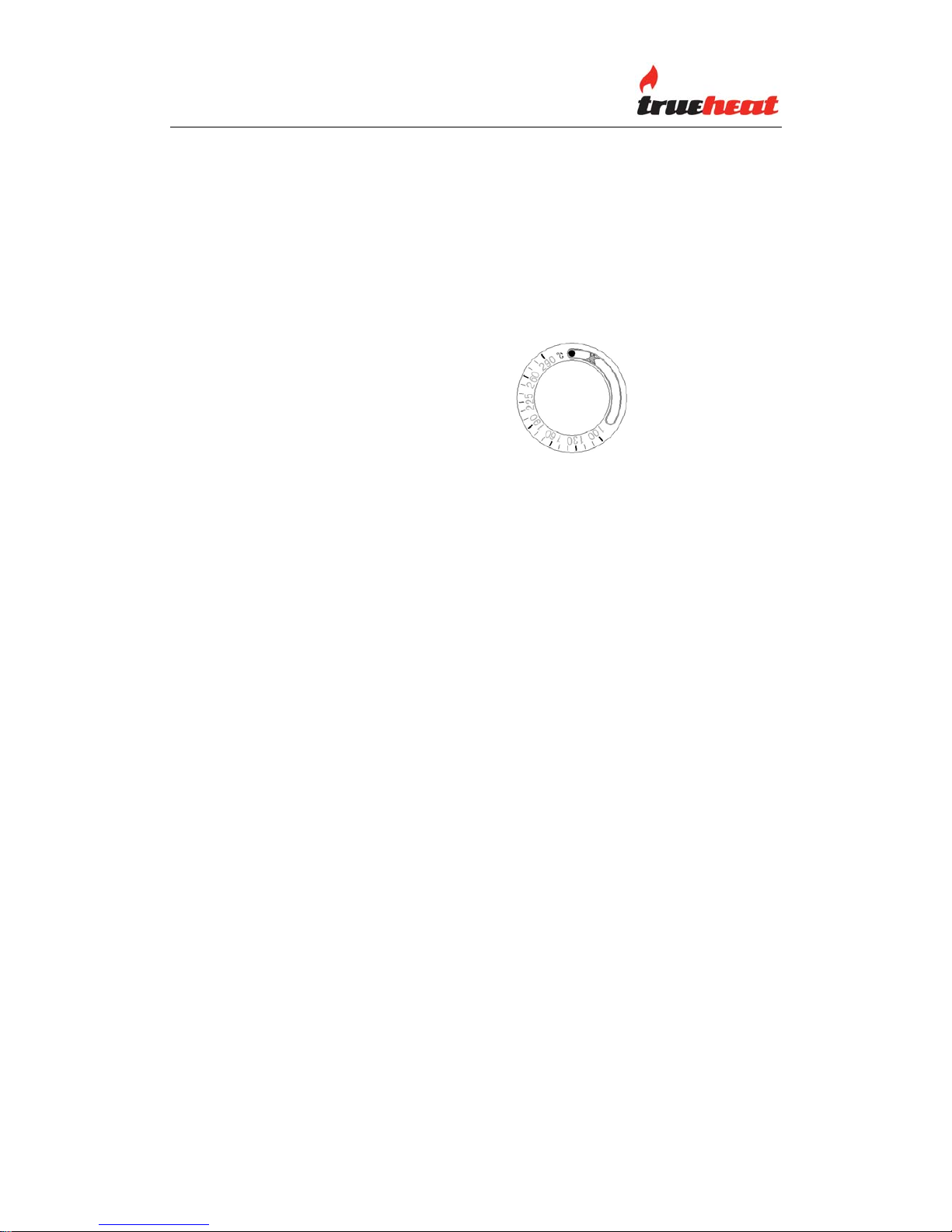
Oven Burner Control
Pilot Flame Ignition
WARNING: OPEN THE OVEN DOOR WHEN LIGHTING THE OVEN
PILOT. ENSURE THE PILOT IS ESTABLISHED BEFORE CLOSING
THE OVEN DOOR. THE PILOT FLAME CAN BE SEEN THROUGH
THE VIEWING HOLE.
Starting from the OFF position ●, press and turn the knob to the PILOT
position ★.
Press the control knob and then press the piezzo igniter – repeat until the pilot
lights. After the pilot lights, keep the control knob depressed for 15 seconds.
Release the knob and check that the pilot flame continues to burn. If the pilot
goes out, repeat the pilot lighting operation.
Temperature Selection
Turn the oven control knob to the desired temperature.
Pilot Standby Position
To turn the main burner off and keep the pilot ON, slightly depress the control
knob and rotate to the PILOT ★ position.
Range Manual Page 16 Revision: 13 Sep 07
OPERATOR MANUAL 130907.doc
Page 17

Shut Down/Pilot OFF
Slightly depress the control knob and rotate to the OFF ● position.
NOTE: If the pilot flame were accidentally extinguished, the flame failure
safety device would operate and cut the gas flow to the main burner. It would
then be necessary to re light the pilot by following the above procedure.
Range Manual Page 17 Revision: 13 Sep 07
OPERATOR MANUAL 130907.doc
Page 18
OPERATOR MAINTENANCE OPERATOR MAINTENANCE
USE ONLY SUITABL E CHEMICALS AND OBSERVE ALL
MANUFACTURER SAFETY REQUIREMENTS FOR SAFE
HANDLING AND USE.
SEASONING THE GRILL
NOTE: The grill surface has protective coating applied at manufacture.
Remove this by washing with hot water and a mild detergent until clean.
Season the grill by applying a thin coat of cooking oil with a cloth to the entire
grill surface. Remove any excess oil with a cloth.
Light the grill burner(s) and set at the lowest level (LEVEL 2). Operate the grill
for about 20 minutes and then wipe away the oil. Repeat this procedure three
times.
IMPORTANT: Only use low heat (LEVEL 2) when seasoning the grill.
NOTE: The grill surface will discolour from heat. Discolouring will not affect the
grill surface function and does not render the grill surface defective.
The grill surface should be cleaned with hot water and detergent.
Normally, if maintained properly, the grill will not need to be seasoned again. If
however, the grill has been overheated and product sticks to the grill surface, it
may be necessary to season the grill again.
Carbon and grease will affect the cooking performance and should be
removed as follows:
After each use, clean the grill thoroughly with a sharp grill scraper and wipe
off any excess debris.
NOTE: Empty the grease drawer as necessary and clean.
Weekly, clean the grill surface thoroughly with a grill pad while the surface is
Range Manual Page 18 Revision: 13 Sep 07
OPERATOR MANUAL 130907.doc
Page 19

still warm (not hot). After cleaning, ensure any detergent/chemical is
thoroughly removed. The grill surface should be covered with a thin film of
cooking oil to prevent rusting.
Note: The grill plate is made of steel and can be easily scored or dented by
careless use of scrapers and spatulas.
CLEANING STAINLESS STEEL
Regularly wipe the surface with hot water and detergent. Rinse the washed
area with a wet sponge and clean water and wipe the area dry to prevent
streaking. Follow this process and wash a small area at a time to prevent
chemical residue and streaking.
Stainless steel may discolour if overheated. These stains can usually be
removed using an appropriate powder/paste. To scrape off heavy deposits of
grease and oil, use only wood or plastic tools as necessary.
Note: Never use steel wool to clean stainless steel.
Note: Damage may occur if chemicals not suitable for stainless steel are used.
OVEN INTERIOR (Enamel)
Note: Remove all oven racks and guides and clean these separately with a
suitable detergent and warm water.
The enamelled oven interior surface should be cleaned regularly with a
suitable oven cleaner.
OPEN TOP BURNERS
Note: Spillage is the major cause of problems to the performance of open top
and pilot burners. Spillage can block gas ports, which then causes burners to
operate inefficiently or, in bad cases, not at all. Clean any spillages as they
occur.
Note: The burner caps are enamelled – do not use abrasive cleaners.
To clean the burners, remove the burner cap and clean with a suitable
detergent and warm water. If the burner ports are blocked, clean these with a
stiff brush. Place the burner cap back on the burner, ignite and check that the
flame is even and comes from all ports (this dries the burner cap).
Range Manual Page 19 Revision: 13 Sep 07
OPERATOR MANUAL 130907.doc
Page 20

If any ports remain clogged, remove the burner cap and complete burner and
clean thoroughly with a suitable detergent and hot water. Dry thoroughly,
ensure the air shutter is fully open, reinstall (ensure the injector is located in
the burner venturi), ignite and check the flame pattern.
Note: The burner flame should be uniformly blue. If yellow flames are present,
this may indicate that grease and dirt are present in the burner throat. Remove
and clean the burner per the above.
ENAMELLED TRIVETS
The enamelled trivets should be removed from the appliance before cleaning.
To clean the trivets, wash with warm water and a suitable detergent using a
soft cloth and then dry.
Note: Do not use abrasives pads or chemicals – these will damage the
enamelling.
For heavily soiled trivets, use a suitable oven cleaner and non-abrasive pad or
brush.
Range Manual Page 20 Revision: 13 Sep 07
OPERATOR MANUAL 130907.doc
Page 21

SERVICE
FOR YOUR SAFETY, ALL SERVICE WORK MUST BE
CARRIED OUT BY AN AUTHORISED PERSON AND USE
ONLY ORIGINAL SUPPLIED AND SPECIFIED PARTS.
TEST ALL FITTINGS, PIPES AND PIPE CONNECTIONS FOR
LEAKS IN ACCORDANCE WITH APPROVED GAS LEAK
TEST PROCESSES AND METHODS. DO NOT USE A
FLAME.
Note: When checking gas pressure, ensure that all other equipment on
the same line is turned “ON”.
RECOMMENDED SERVICE
It is recommended that your appliance be serviced by an authorized person
every 12 months. This period is for guidance purpose only and may vary based
on usage of the equipment and operator care. Prescribed service tasks
include;
• Functional test of all components and clean and adjust as necessary.
• Inspect and clean all gas valves and lubricate with an industry approved
lubricant.
• Inspect all gas piping.
• Check and adjust specified gas pressures.
• Leak test.
• Full operational, performance and safety test.
SERVICE INFORMAT ION
To access gas valves, remove control knobs and the front panel.
To remove a gas valve, disconnect the gas valve at the manifold tee spigot
connection and remove the valve.
To access the oven thermostat, refer SPECIFICATIONS ‘Data Plate Access’.
To access open burner thermocouples/pilots, remove trivets.
To access grill burner thermocouples/pilots/igniters, remove grill plate.
To access oven burner thermocouples/pilots/igniters, remove oven base.
Range Manual Page 21 Revision: 13 Sep 07
OPERATOR MANUAL 130907.doc
Page 22

OPEN AND GRILL BURNER ADJUSTMENTS
Leak Test
Ensure that all valves are in the OFF position.
Turn on the main gas supply valve.
Light all pilots.
Leak test all valves and fittings using approved methods.
Correct any leaks as required and re-check.
Shut off all valves and set thermostat dials to “OFF” position.
Test Point Pressure
The open top and grill gas pressure test point is located on the gas manifold.
The gas manifold and pressure test point is accessed by removing the gas
valve control knobs and the front panel. The test point pressure is shown in the
Nominal Gas Consumption Table and is set with two open top burners
operating at maximum setting.
Pilot Burner Adjustment
Set all pilots so that the flame envelops the tip of the thermocouple by
adjusting the pilot flame adjusting screw within the pilot - clockwise to
decrease, or anti-clockwise to increase.
Service adjustment should not be necessary unless changing the gas valve or
performing gas conversion.
Burner Adjustment
The open top, grill and oven burner orifices are fixed as specified and cannot
be adjusted. The specified gas rate will be achieved if the gas supply
pressure and test point pressure is correct.
The turndown (low flame) setting can be adjusted by adjusting the screw on
the gas valve.
A distinct blue flame over the entire port area of the burner will be achieved at
full rate when the air supply is correct and the air shutter is properly adjusted.
If the flame is yellow and wavy, the cause needs to be established.
WARNING: If you are not competent in performing any service task or require
assistance, please contact Comcater Service 03 8369 4600.
Range Manual Page 22 Revision: 13 Sep 07
OPERATOR MANUAL 130907.doc
Page 23

OVEN CONTROL SETTINGS AND ADJUSTMENTS
Test Point Pressure
The oven burner pressure test point is located on the EUROSIT 630
thermostat. The test point pressure is shown in the Nominal Gas Consumption
Table and is set to the specified pressure AFTER the gas manifold pressure
has been set.
(Reference: SIT Manual 630 EUROSIT Manual – ensure current copy)
Extract from SIT manual – contact manufacturer (SIT) for any updates
All adjustments must be made based on the specific characteristics of the
appliance. Check inlet and outlet pressure using the pressure test points (6
and 7) provided. After testing, carefully seal test points with the provided
screws. Recommended torque: 2.5 Nm.
Adjustment of Maximum and Minimum Outlet Flows
These adjustments must be carried out with the thermostat bulb cold.
Range Manual Page 23 Revision: 13 Sep 07
OPERATOR MANUAL 130907.doc
Page 24

Maximum Flow
Turn the knob to position 7.
Turn the setting screw (2) fully in.
Turn the setting screw anticlockwise to increase gas flow.
CAUTION: The setting screw should not be unscrewed more than 2 turns from
the fully in position.
Minimum Flow
Starting from position 7, turn the knob slowly clockwise to the minimum flow
position (just before the cut-off click).
Turn the screw (3) clockwise to reduce flow.
It is possible to use screws with calibrated bores (available on request) to
replace the maximum by-pass flow setting screw. In this, it is necessary to
screw the calibrated screw fully in with 7 Nm torque.
Adjustment of gas flow to the pilot burner.
Turn the screw (5) clockwise to reduce flow.
IMPORTANT: At the end of all setting and adjustment operations, check gas
seals and the efficiency of the appliance.
After carrying out all adjustments, fit the provided seals and/or block the setting
screw with paint.
Maintenance
The only maintenance operation permitted by SIT Group is replacement of the
thermocouple. This must be carried out by a qualified person according to the
instructions provided with the spare parts.
The above instructions are an extract from ‘SIT Manual 630 EUROSIT
Manual’.
Ensure you contact the manufacturer (SIT Group) for any updates.
Range Manual Page 24 Revision: 13 Sep 07
OPERATOR MANUAL 130907.doc
Page 25

CONVERSION INSTRUCTIONS
TO BE COMPLETED BY AN AUTHORISED PERSON
ENSURE GAS IS ISOLATED WHILST PERFORMING
CONVERSION WORK. PERFORM A LEAK TEST BEFORE
IGNITING AND CALIBRATING BURNER AND PILOT
ADJUSTMENTS.
TO PROPANE GAS
Regulator Change regulator to PROPANE gas configuration
and adjust as necessary
Open Burner/Grill Burner Access and change the injectors to PROPANE Gas
injectors (refer Nominal Gas Consumption
Table)
Oven Burner Access and change the injector to a PROPANE
Gas Injector (refer Nominal Gas Consumption
Table)
LEAK TEST IN ACCORDANCE WITH APPROVED METHODS
Ignite burners and adjust.
AMEND DATA PLATE AND APPLY ‘PROPANE’ GAS LABEL
TO NATURAL GAS (NG)
Regulator Change regulator to NG gas configuration and
adjust as necessary
Open Burner/Grill Burner Access and change the injectors to a NG Injectors
(refer Nominal Gas Consumption Table)
Oven Burner Access and change the injector to a NG Injector
(refer Nominal Gas Consumption Table)
Range Manual Page 25 Revision: 13 Sep 07
OPERATOR MANUAL 130907.doc
Page 26

LEAK TEST IN ACCORDANCE WITH APPROVED METHODS
Ignite burners and adjust
AMEND DATA PLATE AND APPLY ‘NATURAL GAS’ LABEL
SPARE PARTS
A list of major spare part items is shown at the end of this manual.
These parts and all other parts used in the Comcater range are available from
Comcater.
Range Manual Page 26 Revision: 13 Sep 07
OPERATOR MANUAL 130907.doc
Page 27

TROUBLE SHOOTING
ALL SERVICE WORK TO BE COMPLETED BY AN
AUTHORISED PERSON.
ALL BURNERS
CONDITION CHECK
Pilot will not light. Gas supply is on and gas pressure is correct
Blocked pilots
Pilot adjusting screw
Pilot repeatedly goes out. Pilot flame size and position
Thermocouple
Flame safety device
Yellow Burner Flame. Primary air and adjust air shutter
Flame lifting off burner ports. Primary air
Air shutter
‘Popping’ after turning off. Primary air
Air shutter
Burner flame too large. Gas pressure
Delayed ignition. Pilot flame
Burner and ports clean
Air shutter
Gas pressure
Piezzo will not spark. Igniter lead, igniter and electrode
Flame burns back to orifice Primary air
Air shutter
Range Manual Page 27 Revision: 13 Sep 07
OPERATOR MANUAL 130907.doc
Page 28

OVEN
Incorrect oven temperature Oven thermostat and control dial position
Burner shuts off at set Thermostat/by-pass
temperature
Range Manual Page 28 Revision: 13 Sep 07
OPERATOR MANUAL 130907.doc
Page 29

RANGE OPTIONS - TOP ONLY
MODEL T90-6
MODEL T90-0-90G
MODEL T90-4-30GR
MODEL T90-4-30GL
MODEL T90-2-60GL
MODEL T90-2-60GR
MODEL T60-0-60G
MODEL T60-4
File Name: Range Option 1(130907)
Range Manual Page 29 Revision: 13 Sep 07
OPERATOR MANUAL 130907.doc
Page 30

RANGES COMPLETE WITH OVEN
MODEL R90-0-90G
MODEL R90-6
MODEL R90-4-30GL MODELR90-4-30GR
MODELR90-2-60GL
MODEL R90-2-60GR
File Name: Range Option 2 (130907)
Range Manual Page 30 Revision: 13 Sep 07
OPERATOR MANUAL 130907.doc
Page 31

MAJOR PARTS IDENTIFICATION
IDENTIFICATION PART NUMBER ITEM NAME
CCE KB-F60P Flame Failure Gas Valve F60P
CCE KB-99301/270 Knob Black – Suit F60P (Open Top and Grill Burners)
CCE KB-99301/DF
CCE KB-99301/DR
CCE KB-99301/DG
Decal Knob - Front
Decal Knob - Rear
Decal Knob - Grill
CCE KB-99301/EP Escutcheon – Knob/Pilot Position
CCE B21002 Oven Thermostat Knob
CCE KB-100.017 Pilot 1FX2H (Open Burners)
CCE KB-100.011
CCE KG-915036
Pilot 3FX3H (Grill/Oven Burners With Igniter Holder)
Electrode Pilot/Bunsen (Bent Electrode)
Range Manual Page 31 Revision: 13 Sep 07
OPERATOR MANUAL 130907.doc
Page 32

CCE KB-6402 Manifold Plug 1/4" BSP
CCE KB-WRB/E Rear Burner Complete (Enamelled Cap)
CCE KB-WFB/E Front Burner Complete (Enamelled Cap)
CCE KB-WTB/E Trivet (Enamelled)
CCE KB-WPS Pot Stand (Stainless Steel)
CCE KB-WOB Oven Burner
CCE KB-WGB Grill Burner
CCE KB-WMB Manifold Bush ¼” BSP Female
CCE KB-WMT Manifold Tee ¼” BSP Male
Range Manual Page 32 Revision: 13 Sep 07
OPERATOR MANUAL 130907.doc
Page 33

CCE KB-WMT/TP
Manifold Tee ¼” BSP Male Complete With Pressure
Test Point
CCE KB-WIH/L Injector Holder Left Hand Aluminium
CCE KB-WIH/R Injector Holder Right Hand Aluminium
CCE KG-AT63503C Aluminium Tube 1/4" (6.35mm) 3 Metres
CCE KG-200090 Thermocouple 900XM9XUnif/Sleeve
CCE KG-200021 Thermocouple 1500XM9XUnif/Sleeve
CCE KG-200255 Thermocouple 320XM9XUnif/Sleeve
CCE KG - 348130
CCE KG - 348140
CCE KG – 348220
CCE KG - 348230
Injector 1/8" BSP Grill Burners (LPG 1.30mm)
Injector 1/8" BSP Open Burners (LPG 1.40mm)
Injector 1/8" BSP Grill Burners ((NG 2.20mm)
Injector 1/8" BSP Open Burners (NG 2.30mm)
CCE KG - 72150
CCE KG - 72260
Injector RBA C/W Nut & Olive 3/8" Tube (Oven)
(LPG 1.50mm)
Injector RBA C/W Nut & Olive 3/8" Tube (Oven)
(NG 2.60mm Orifice )
Range Manual Page 33 Revision: 13 Sep 07
OPERATOR MANUAL 130907.doc
Page 34

CCE Q26004
Oven Shelf
CCE Q26100 Oven Rack Guide (Left Hand)
CCE Q26101 Oven Rack Guide (Right Hand)
CCE B21001 Oven Handle Bracket
CCE KG-073964 Piezzo Igniter and Nut – Red Button
CCE KG - HT1500
CCE KG - HT250
Lead Ignition H/T 1500 mm (OVEN)
Lead Ignition H/T
250 mm (GRILL)
CCE KB-RV48LM-66
CCE
MAXITROL GAS REGULATOR 3/4" BSP NG
MAXITROL CONVERSION KIT LPG
Source File: PARTSIDENTIFICATION 130907
Range Manual Page 34 Revision: 13 Sep 07
OPERATOR MANUAL 130907.doc
Page 35

Range Manual Page 35 Revision: 13 Sep 07
OPERATOR MANUAL 130907.doc
Page 36

Range Manual Page 36 Revision: 13 Sep 07
OPERATOR MANUAL 130907.doc
Page 37

Range Manual Page 37 Revision: 13 Sep 07
OPERATOR MANUAL 130907.doc
Page 38

Range Manual Page 38 Revision: 13 Sep 07
OPERATOR MANUAL 130907.doc
Page 39

Range Manual Page 39 Revision: 13 Sep 07
OPERATOR MANUAL 130907.doc
Page 40

Range Manual Page 40 Revision: 13 Sep 07
OPERATOR MANUAL 130907.doc
Page 41

Range Manual Page 41 Revision: 13 Sep 07
OPERATOR MANUAL 130907.doc
Page 42

Range Manual Page 42 Revision: 13 Sep 07
OPERATOR MANUAL 130907.doc
Page 43

Range Manual Page 43 Revision: 13 Sep 07
OPERATOR MANUAL 130907.doc
Page 44

Range Manual Page 44 Revision: 13 Sep 07
OPERATOR MANUAL 130907.doc
Page 45

Range Manual Page 45 Revision: 13 Sep 07
OPERATOR MANUAL 130907.doc
Page 46

Range Manual Page 46 Revision: 13 Sep 07
OPERATOR MANUAL 130907.doc
Page 47

Range Manual Page 47 Revision: 13 Sep 07
OPERATOR MANUAL 130907.doc
Page 48

Range Manual Page 48 Revision: 13 Sep 07
OPERATOR MANUAL 130907.doc
Page 49

Range Manual Page 49 Revision: 13 Sep 07
OPERATOR MANUAL 130907.doc
Page 50

Range Manual Page 50 Revision: 13 Sep 07
OPERATOR MANUAL 130907.doc
Page 51

Range Manual Page 51 Revision: 13 Sep 07
OPERATOR MANUAL 130907.doc
Page 52

Range Manual Page 52 Revision: 13 Sep 07
OPERATOR MANUAL 130907.doc
Page 53

Range Manual Page 53 Revision: 13 Sep 07
OPERATOR MANUAL 130907.doc
Page 54

Range Manual Page 54 Revision: 13 Sep 07
OPERATOR MANUAL 130907.doc
Page 55

Range Manual Page 55 Revision: 13 Sep 07
OPERATOR MANUAL 130907.doc
Page 56

Range Manual Page 56 Revision: 13 Sep 07
OPERATOR MANUAL 130907.doc
Page 57

Range Manual Page 57 Revision: 13 Sep 07
OPERATOR MANUAL 130907.doc
Page 58

Range Manual Page 58 Revision: 13 Sep 07
OPERATOR MANUAL 130907.doc
Page 59

Range Manual Page 59 Revision: 13 Sep 07
OPERATOR MANUAL 130907.doc
Page 60

N o t e s
_______________________________________________________________________
_______________________________________________________________________
_______________________________________________________________________
_______________________________________________________________________
_______________________________________________________________________
_______________________________________________________________________
_______________________________________________________________________
_______________________________________________________________________
_______________________________________________________________________
_______________________________________________________________________
_______________________________________________________________________
_______________________________________________________________________
_______________________________________________________________________
_______________________________________________________________________
_______________________________________________________________________
_______________________________________________________________________
_______________________________________________________________________
Range Manual Page 60 Revision: 13 Sep 07
OPERATOR MANUAL 130907.doc
 Loading...