

Page 1
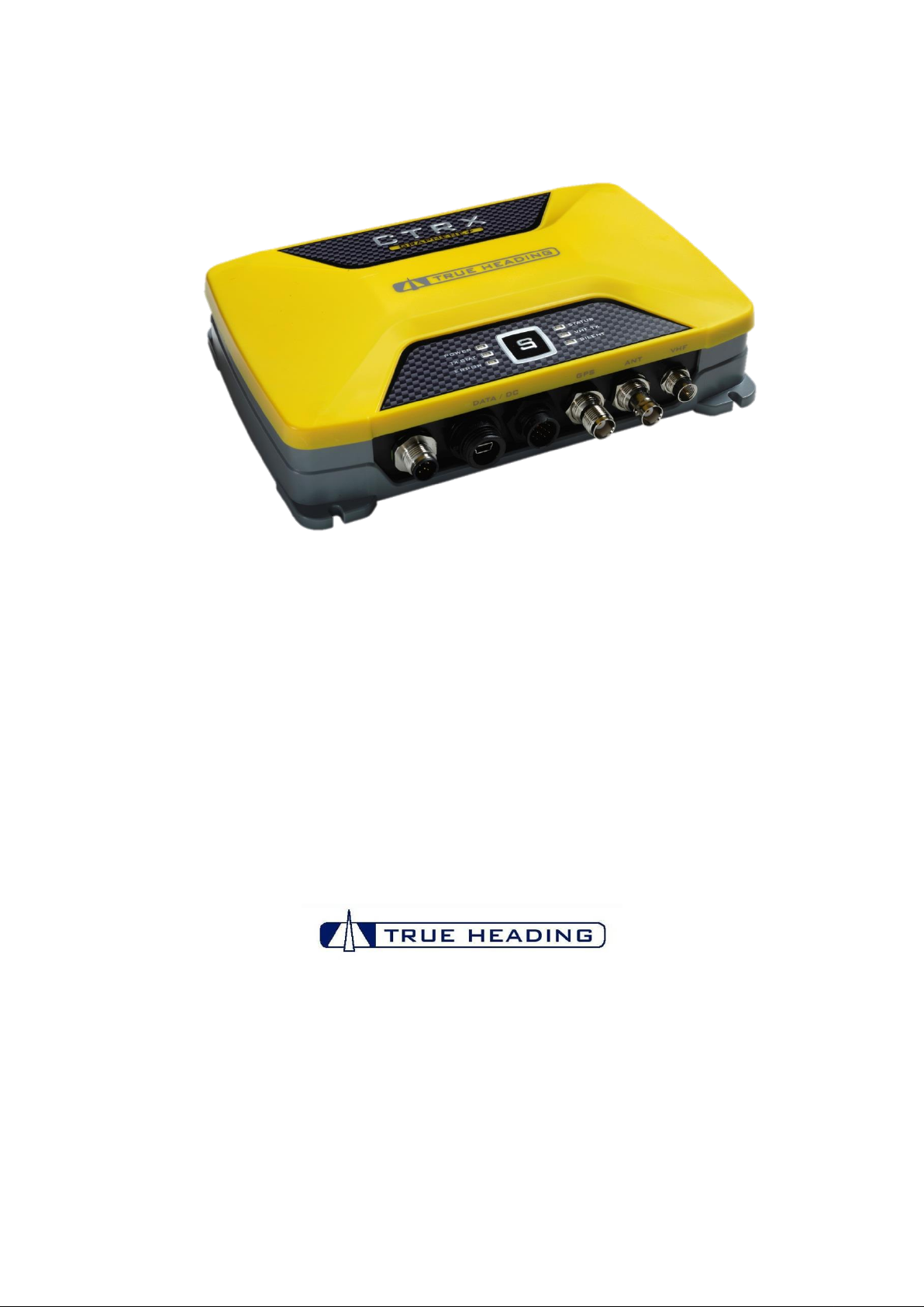
OPERATION & INSTALLATION MANUAL
AIS CTRX GRAPHENE
Class B AIS Transponder
Version 1.9E
© True Heading 2013
The manual may not in any aspect be copied without the prior authorization from True Heading AB.
Page 2

AIS CTRX GRAPHENE Class B AIS Transponder Manual
TABLE OF CONTENTS
TABLE OF CONTENTS ........................................................................................................ 2
ABOUT THIS MANUAL ......................................................................................................... 3
IMPORTANT INFORMATION ............................................................................................... 4
EC DECLARATION OF CONFORMITY ................................................................................ 6
INTRODUCTION ................................................................................................................... 7
SAFETY INFORMATION ...................................................................................................... 8
WARRANTY .......................................................................................................................... 9
SUPPORT ............................................................................................................................10
PRODUCT SPECIFICATION ...............................................................................................11
Getting started ....................................................................................................... 12
BEFORE YOU BEGIN THE INSTALLATION ........................................................................13
INSTALLATION ....................................................................................................................14
CONNECTION TO THE DC POWER SUPPLY ....................................................................20
CONNECTION OF AN EXTERNAL SILENT SWITCH WITH LED INDICATOR ...................21
PROAIS2 CONFIGURATION SOFTWARE ..........................................................................22
NOTES .................................................................................................................................29
Mounting Template ................................................................................................ 30
APPENDIX A CONFIGURING THE AIS CTRX GRAPHENE ............................................31
APPENDIX B ANTENNAS AND ANTENNA MOUNTING..................................................33
GPS Antenna ......................................................................................................... 33
VHF antenna for AIS use ....................................................................................... 33
WARNINGS ................................................................ ................................ ........... 34
APPENDIX C WIFI OPTION .............................................................................................35
APPENDIX D CTRX GRAPHENE NMEA 2000 PGN LIST ................................................36
1.9E 2 CTRX GRAPHENE Manual
Page 3

AIS CTRX GRAPHENE Class B AIS Transponder Manual
Version
Date
Responsible
Approved
Changes
1.0PE
2012-12-14
Anders Bergström
Nils Willart
Preliminary release
1.1PE
2013-03-08
Nils Willart
Update
1.2PE
2013-04-09
Nils Willart
Editorial
1.3PE
- - -
Intermediate, not issued
1.4E
2013-05-21
Nils Willart
PGN list added
1.5E
2014-03-03
Nils Willart
USB caution
1.51E
2014-09-11
Nils Willart
Editorial
1.6E
2014-09-11
C. Ander Smith (legal)
Legal comments
1.7E
2014-09-15
Nils Willart
Editorial, WiFi added
1.8E
2014-05-05
Nils Willart
Editorial
1.9E
2015-07-08
Nils Willart
RF exposure added
ABOUT THIS MANUAL
In accordance with our policy of continuous development and product improvement the AIS CTRX
GRAPHENE hardware and/or software may be upgraded from time to time and future versions of the
AIS CTRX GRAPHENE may therefore not correspond exactly with this manual.
When necessary, upgrades to the product are made. These will be accompanied by updates or
addendum to this manual.
Please take time to read this manual carefully in order to fully understand the functions and
preparations necessary for the installation and operation of your AIS transponder.
Information contained in this manual is subject to change without notice.
True Heading AB disclaims any liability for consequences arising from omissions or inaccuracies in
this manual and any other documentation provided with this product.
UNDER NO CIRCUMSTANCES SHALL TRUE HEADING AB BE LIABLE FOR INDIRECT OR
CONSEQUENTIAL DAMAGES IN CONNECTION WITH OR ARISING OUT OF THE USE OF ANY
OF OUR PRODUCTS.
Revision history
1.9E 3 CTRX GRAPHENE Manual
Page 4

AIS CTRX GRAPHENE Class B AIS Transponder Manual
IMPORTANT INFORMATION
Licensing
In most countries the operation of an AIS unit is included under the vessels marine VHF radio licence
provisions. The user/owner of the vessel on to which the AIS unit is to be installed must therefore
possess a valid VHF radiotelephone licence which lists the AIS system and the vessel Call Sign and
MMSI number.
Please contact the relevant authority in your country for more information.
US Customers:
There are specific laws in the USA regarding the configuration of AIS class B transceivers. The entry
of static data into a Class B AIS device shall be performed by the vendor of the device or by an
appropriately qualified person in the business of installing marine communications equipment on
board vessels. In no event shall the entry of static data into a Class B AIS device be performed by the
user of the device or the licensee of a ship station.
WARNING:
It is a violation of the rules of the Federal Communications Commission to input an MMSI that
has not been properly assigned to the end user, or to otherwise input any inaccurate data in
this device.
FCC notice
This equipment has been tested and found to comply with the limits for a class B digital device,
pursuant to part 15 of the FCC Rules. These limits are designed to provide reasonable protection
against harmful interference in a residential installation. This equipment generates, uses and can
radiate radio frequency energy and, if not installed and used in accordance with the instructions, may
cause harmful interference to radio communications.
This device complies with part 15 of the FCC Rules. Operation is subject to the following two
conditions:
(1) This device may not cause harmful interference, and
(2) This device must accept any interference received, including interference that may cause
undesired operation.
Changes or modifications not expressly approved by the party responsible for compliance could void
the user's authority to operate the equipment.
Industry Canada notice
This device complies with Industry Canada licence-exempt RSS standard(s). Operation is subject to
the following two conditions:
1. This device may not cause interference, and
2. This device must accept any interference, including interference that may cause undesired
operation of the device.
Le présent appareil est conforme aux CNR d'Industrie Canada applicables aux appareils radio
exempts de licence. L'exploitation est autorisée aux deux conditions suivantes :
1. L'appareil ne doit pas produire de brouillage, et
2. L'utilisateur de l'appareil doit accepter tout brouillage radioélectrique subi, même si le
brouillage est susceptible d'en compromettre le Fonctionnement.
1.9E 4 CTRX GRAPHENE Manual
Page 5

AIS CTRX GRAPHENE Class B AIS Transponder Manual
RF Exposure
The required compliance boundary for the AIS Graphene is:
Occupational: 0.13 m
General population: 0.27 m
To comply with the requirements set by ICNIRP, FCC, RSS and ARPANSA the VHF antenna shall be
installed in such a way that the minimum distance from the antenna to a boundary 0.5 m from where
humans can reside is maintained.
The Graphene models equipped with WiFi shall be installed in such a way that the minimum distance
to a boundary from the rear towards humans is not less than 20 cm.
1.9E 5 CTRX GRAPHENE Manual
Page 6

AIS CTRX GRAPHENE Class B AIS Transponder Manual
Standard
Description
IEC 62287-1, Ed2: 2006-03
Maritime navigation and radio communication
equipment and systems – Class B ship borne
equipment of the automatic identification system
(AIS) – Part 1: Carrier-sense time division
multiple access (CSTDMA) techniques
IEC 60945, Ed4: 2002-08
Maritime navigation and radio communication
equipment and systems – General requirements
– Methods of testing and required test results
IEC 61162-1, Ed2:
Maritime navigation and radio communication
equipment and systems – Digital interfaces –
Part 1: Single talker and multiple listeners
IEC 61108-1:
GLOBAL NAVIGATION SATELLITE SYSTEMS
(GNSS) – Part 1: Global positioning system
(GPS) -Receiver equipment - Performance
standards, methods of testing and required test
results
EN 301 843-1 v2.1:
Electromagnetic compatibility and Radio
spectrum Matters (ERM); Electromagnetic
Compatibility (EMC) standard for marine radio
equipment and services; Part 1: Common
technical requirements
EN 50383: 2002
Basic standard for calculation and measurement
of electromagnetic field strength and SAR related
to human exposure from radio base stations and
fixed terminal stations for wireless
telecommunications system (110MHz – 40GHz)
EN 60950-1:2002
Information technology equipment – Safety –
Part 1: General requirements
NMEA 2000 Edition 2.20
NMEA 2000 Standard for serial-data networking
of marine electronic devices
AT
BG
BE
CY
CZ
DK
EE
FI
FR
DE
GR
HU
IE
IT
LV
LT
LU
MT
NL
PL
PT
RO
SK
SL
ES
SE
GB
IS
LI
NO
CH
EC DECLARATION OF CONFORMITY
This product complies with the necessary standards under the European R&TTE directive for Article
3.1(a), 3.1(b), 3.2 and 3.3(e). The following standards have been followed in pursuance of this:
True Heading AB declares that this product is in compliance with the essential requirements and other
provisions of the R&TTE directive 1995/5/EC.
The product carries the CE mark, notified body number and alert symbol as required by the R&TTE
directive
This True Heading product can be used in the following European Community Countries:
1.9E 6 CTRX GRAPHENE Manual
Page 7
AIS CTRX GRAPHENE Class B AIS Transponder Manual
INTRODUCTION
We would like to thank you for choosing True Heading AB as supplier of your AIS Class B
Transponder. The AIS CTRX GRAPHENE is a high quality AIS Class B Transponder using the latest
technology. AIS CTRX GRAPHENE makes it possible to receive information from ships, buoys,
lighthouses, SAR helicopters, Coastguard units, Pilot boats, Weather station etc. and to send
information about your own ship to others that are equipped with Automatic Identification System (AIS)
transponders or receivers. SEE AND BE SEEN
It is today, according to the IMO SOLAS regulation a requirement for all ships above 300 GT to carry
AIS. This means that a large number of ships and other types of navigational information providers will
be seen by your AIS CTRX GRAPHENE and contribute to enhanced safety in your navigation.
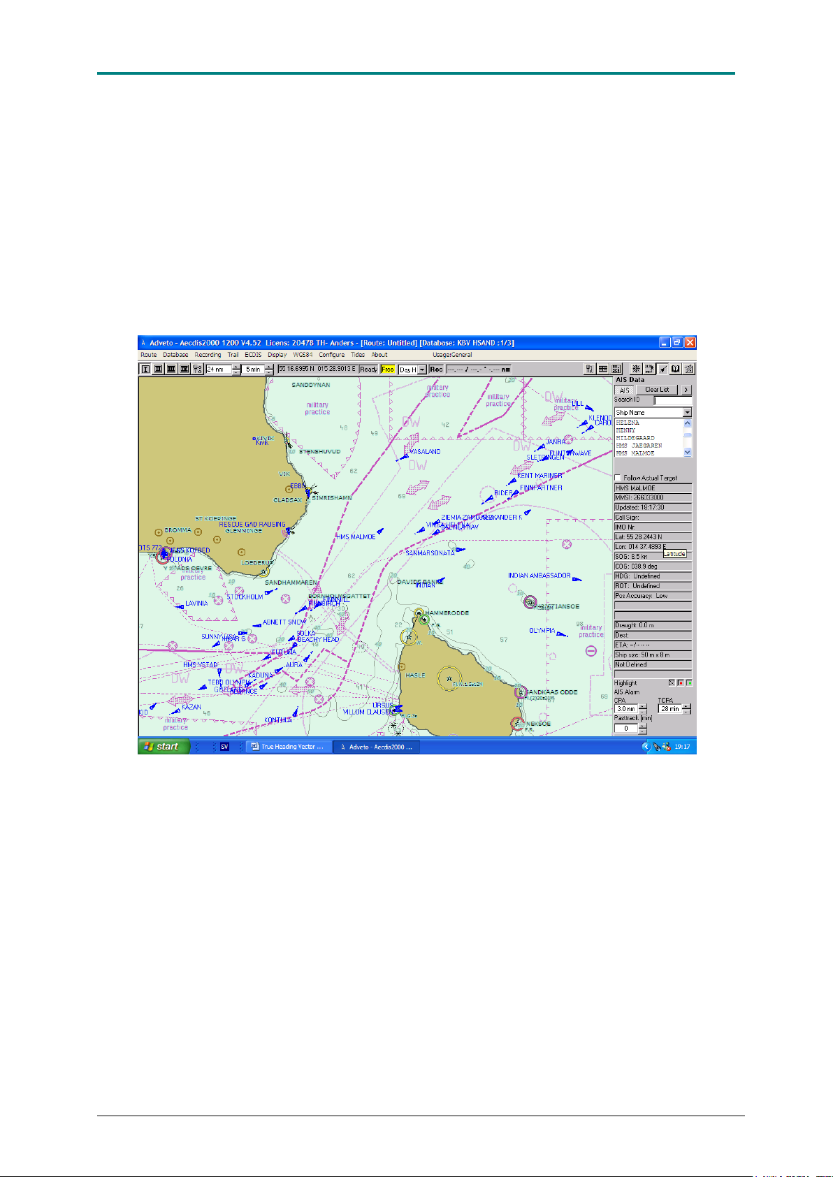
Picture 1 Real traffic scenario between Sweden and Bornholm (Denmark)
It is of utmost importance that you read this manual before you start to install and use your AIS CTRX
GRAPHENE.
1.9E 7 CTRX GRAPHENE Manual
Page 8

AIS CTRX GRAPHENE Class B AIS Transponder Manual
SAFETY INFORMATION
Before you start using the AIS CTRX GRAPHENE transponder it is important that you read and fully
understand the instructions in the installation manual. You should only proceed with the installation if
you are confident that you will be able to do so.
True Heading AB cannot be held liable for any injury or damage caused by, during or because of the
installation of AIS CTRX GRAPHENE. The AIS CTRX GRAPHENE is used at your own risk and it
shall be kept in mind that the validity of the AIS and GPS data depends on the full co-operation of
other users and systems.
AIS CTRX GRAPHENE is a navigation aid and is used together with other similar systems like radar,
optical lookout etc. to maintain safety at sea. The AIS CTRX GRAPHENE installation should be
inspected regularly and frequently checked by the user to maintain proper operation quality.
Remember that navigation and safety of lives at sea always requires proper seamanship and that the
AIS CTRX GRAPHENE is an aid and not a replacement for such qualities.
NOT ALL VESSELS CARRY AIS. IT IS THEREFORE IMPORTANT TO KEEP A PROPER
LOOKOUT AT ALL TIMES AND TO USE ALL AVAILABLE MEANS TO AVOID COLLISIONS AND
ACCIDENTS.
GPS MAY FROM TIME TO TIME INCLUDE ERRORS; THEREFORE, USERS MUST ALWAYS
VERIFY INDICATED POSITIONS RECEIVED FROM THE GPS BUILT IN TO THE TRANPONDER
WITH OTHER AVAILABLE MEANS.
General notice on GNSS reception
The AIS (Automatic Identification System) unit mostly utilise GNSS (Global Navigation Satellite
System) as GPS or GLONASS to determine position.
The accuracy of these systems is variable and can be affected by factors such as the positioning of
the receiving antenna, the number of satellites available at the time, angle of reception and if satellites
are healthy or not.
It is desirable to check and verify both your and other vessels AIS position data as often as possible
using visual or if available radar based observations.
Compass safe distance: 0.5m or greater for 0.3° deviation
1.9E 8 CTRX GRAPHENE Manual
Page 9

AIS CTRX GRAPHENE Class B AIS Transponder Manual
WARRANTY
General
True Heading AB warrants its AIS CTRX GRAPHENE transponder (the “Product”) against defects in
design, material and workmanship for a period of two (2) years from the date of purchase (the
“Warranty”). The Warranty covers costs for spares, labour, and return shipment; return of the defective
Product to True Heading AB shall be at purchaser’s risk and expense. Should any failure of the
Product to conform with the above Warranty develop during the specified period under normal and
proper use and provided the Product has been properly installed and maintained, True Heading AB
shall, if given prompt notice of the alleged failure to conform, correct such non-conformity at the option
of True Heading AB by repair, replacement, or by refund of the purchase price of the non-conforming
Product.
The above Warranty shall terminate and be voided under the following circumstances: (a) the Product
serial number is missing, (b) modification, repair or alteration by anyone other than an True Heading
authorized service provider; (c) improper operation, maintenance or installation, including but not
limited to broken seals; (d) damage during shipment; (e) operation, handling or other dealings with
Product in a negligent manner; or (f) abnormal conditions or temperature, moisture, dirt or corrosive
matter.
TO THE EXTENT PERMITTED BY APPLICABLE LAW, THE WARRANTIES, RIGHTS AND
REMEDIES SET FORTH IN THIS SECTION ARE EXCLUSIVE AND IN LIEU OF ALL OTHER
WARRANTIES, REPRESENTATIONS, CONDITIONS, RIGHTS AND REMEDIES WITH RESPECT
TO ANY PRODUCT, EXPRESS OR IMPLIED, STATUTORY OR OTHERWISE, AND WHETHER
WRITTEN OR ORAL; ALL OTHER WARRANTIES, REPRESENTATIONS, CONDITIONS, RIGHTS
AND REMEDIES, INCLUDING, BUT NOT LIMITED TO, ANY WARRANTY OF MERCHANTABILITY,
DURABILITY OR FITNESS FOR A PARTICULAR PURPOSE, ARE HEREBY EXPRESSLY
DISCLAIMED, EXCLUDED AND WAIVED BY PURCHASER TO THE FULLEST EXTENT
PERMITTED BY LAW.
Correction of non-conformities in the manner and for the period of time provided above shall be the
exclusive remedy and shall constitute fulfilment of all liabilities of True Heading AB whether in
warranty, contract, negligence, tort or otherwise with respect to the quality of the Product.
Warranty procedures
Warranty claims shall be made to the place where you purchased the Product or direct to True
Heading AB through mail, fax or e-mail to our support department. Replaced Product shall become the
property of True Heading AB.
PLEASE KEEP YOUR PROOF OF PURCHASE as it is required for a Warranty claim.
Replacements pursuant to the Warranty shall not renew or extend the applicable original Warranty
period; provided, however, that any such replacement Product shall be warranted for the time
remaining under the original Warranty period or for 30 days, whichever is longer.
Other issues
Proper seamanship and common sense must be exercised when using the AIS CTRX GRAPHENE;
the Products shall only be seen as a navigational aid.
True Heading AB reserves the right to change the specification of the Product without prior notice.
IF YOU ARE NOT ABLE TO ACCEPT THE TERMS ABOVE, PLEASE RETURN THE AIS CTRX
GRAPHENE TO YOUR RETAILER FOR FULL CREDIT BEFORE OPENED AND USED.
1.9E 9 CTRX GRAPHENE Manual
Page 10

AIS CTRX GRAPHENE Class B AIS Transponder Manual
SUPPORT
If you need support, please contact the closest reseller or the location where you acquired the product.
The manufacturer will only provide support direct if these procedures are followed. The support case
has to be registered properly through our webpage at www.trueheading.se.
In order to ensure that you receive important information register the purchase of your product by
sending an e-mail to [email protected] where you state the serial number, purchase date, your
name, address and where you bought the product.
In accordance with our policy to always offer products with the latest in development and
enhancements, future versions of AIS CTRX GRAPHENE may differ somewhat from what is described
in this manual. Updated versions of the manual are always available for download at our homepage
www.trueheading.se.
1.9E 10 CTRX GRAPHENE Manual
Page 11

AIS CTRX GRAPHENE Class B AIS Transponder Manual
PRODUCT SPECIFICATION
Dimensions: 210 x 144 x 50 mm (L x W x H)
Weight: 0.45 kg GRAPHENE
0.5 kg GRAPHENE+
Power: DC 12-24V (min. 10V, max. 32V)
Average power consumption 4W (GRAPHENE)
Average power consumption 4.5 W (GRAPHENE+)
Nominal current rating: 350 mA @ 12 VDC (receive)
Peak current rating: 1.2A @ 12VDC (transmitting)
GPS Receiver (AIS Internal): IEC 61108-1 compliant
50 channels
Data Interfaces: USB (mini B), Programming and test interface
NMEA 2000 LEN (Load Equivalence Number) = 1
NMEA 0183, RS422, 38400 baud
Connectors: VHF Antenna connector = BNC (Female)
GPS Antenna connector = TNC (Female)
USB B serial data (USB mini connector)
NMEA 0183/DC power connector
NMEA 2000 connector
VHF Radio = FME (Male) (GRAPHENE+ only)
VHF Transceiver: 1 Transmitter, 2 Receivers
Frequency: 156.025 to 162.025 MHz
Receiver sensitivity: <- 110dBm @ 20% PER
RF Output Power: 2 W (50Ω)
Channel Bandwidth: 25 kHz
Data Bit rate: 9600 b/s ± 50 ppm (GMSK) AIS
1200 b/s ± 30 ppm (FSK) DSC
Environmental: IEC 60945, Operating Temperature: -15ºC to +55ºC
IEC 62287-1, Section 5, Cat b: protected from the weather
Compass safe distance: 0.5m or more for 0.3° deviation.
LED indicators: POWER Green
STATUS Green
TX STAT Yellow
ERROR Red
VHF Yellow
SILENT Blue
1.9E 11 CTRX GRAPHENE Manual
Page 12
AIS CTRX GRAPHENE Class B AIS Transponder Manual
1
AIS CTRX GRAPHENE Class B Transponder
P/N 0012-001-000
1
Data / DC cable (1 m)
P/N 0012-770-000
1
USB mini cable 1 m
P/N 0012-980-000
1
BNC to UHF adapter
P/N 0012-989-000
1
CD incl. manual, set-up software and AIS information
P/N 0012-972-000
1
AIS CTRX GRAPHENE Class B Transponder
P/N 0012-002-000
1
Data / DC cable (1 m)
P/N 0012-770-000
1
USB mini cable 1 m
P/N 0012-980-000
1
BNC to UHF adapter
P/N 0012-989-000
1
Coaxial cable AIS to VHF with connectors (2 m)
P/N 0010-980-000
1
CD incl. manual, set-up software and AIS information
P/N 0012-972-000
1
VHF marine band antenna (0dBd) with cable and UHF or
BNC type coaxial connector.
1 GPS antenna (active antenna, built-in LNA, 20dB gain min.,
5VDC) with cable and TNC coaxial connector
2
3A Fuse with fuse holder
1
DC cable min. AWG 16, red and black
4
Mounting screws
1
Installation materials such as mounts for the antennas,
cable ties, screws, connection blocks etc.
Getting started
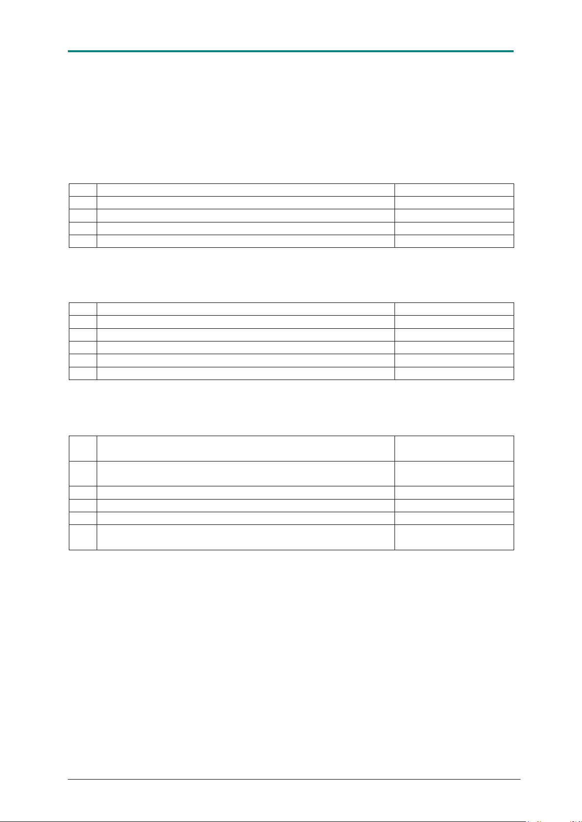
Before AIS CTRX GRAPHENE is installed, you should check that you have all the equipment you
need for the installation and that nothing is missing from your delivery. The AIS CTRX GRAPHENE
comes in two versions the GRAPHENE and the GRAPHENE+ version. The plus version also contains
a built in antenna splitter making it possible to use the same VHF antenna for both the AIS and the
VHF radio.
AIS CTRX GRAPHENE comes with the following parts:
AIS CTRX GRAPHENE + comes with the following parts:
The following may be needed to finish your installation but is not included:
1.9E 12 CTRX GRAPHENE Manual
Page 13

AIS CTRX GRAPHENE Class B AIS Transponder Manual
BEFORE YOU BEGIN THE INSTALLATION
Before you begin the installation, you should decide on where you want to place your AIS
CTRX GRAPHENE unit.
Place the transponder in in a position where you will be able to see the LED’s on the front.
This will make it easy to monitor the functions and make sure that the unit is working
properly.
The transponder is designed to be installed were it is protected from the weather. The
transponder is NOT intended for installation outdoors or anywhere it will be exposed to direct
sunlight, moist or risk of water splashing.
The transponder should be installed in a place where the length of the antenna cables can
be kept as short as possible, but also where DC power and access to other equipment you
would want to connect the AIS to is conveniently available.
The AIS CTRX GRAPHENE has 3 external data ports. 2 of them are preferably used for the
connection to a plotter (the NMEA0183/RS422 or the NMEA 2000 port). A USB port (mini
type) is available for connection to a PC. This is used for the configuration and maintenance
of the unit.
Important when using the USB interface:
The USB port built into this product is not isolated from the vessel power supply, VHF
antenna ground or GPS antenna ground. Please observe the following procedures when
connecting the USB port to avoid grounding problems;
If the computer is permanently installed on the vessel and/ or electrically connected to any
other vessel equipment, including power supplies, it is recommended that connection is
made using NMEA0183 or NMEA2000 connections. These benefit from being specifically
designed for use in the marine environment and provide isolated and robust data transfer
between your devices.
If a battery powered laptop is being used then it is recommended to switch off the computer,
connect the USB cable and then switch on the laptop. This will help to ensure that all
equipment grounds are correctly referenced before use, minimising any risk of equipment
damage.
DC supply connection
If you are installing the AIS CTRX GRAPHENE+ version or using a Class B VHF splitter with
the standard CTRX Graphene it is recommended that you connect the DC power leads to the
same DC power connection point as your VHF.
Antennas
There are antennas available specifically made for use with AIS equipment but any standard
type marine band VHF antenna will work. The antenna gain should not exceed 0 dBd.
Place your VHF antenna as high as possible but at least 2.5-3 m above the water surface. If
you are installing a separate AIS antenna you should make sure that it is separated as much
as possible from other VHF antennas to avoid interference.
GPS antennas should be installed in such a way that the antenna top surface has a free and
unobstructed view of the horizon. Make sure that the antenna is not placed nearby metal
objects in order to minimize reflections of the received signal. GPS antennas should not be
placed in the vicinity of high power HF or satellite communications equipment.
1.9E 13 CTRX GRAPHENE Manual
Page 14
AIS CTRX GRAPHENE Class B AIS Transponder Manual
Pin
Signal
Color marking
1
Signal ground
BROWN
2
Power supply Voltage GND (-)
BLUE
3
SILENT LED (Blue)
WHITE
4
Signal ground
GREEN
5
NMEA 0183/RS-422 TX B (-)
YELLOW
6
NMEA 0183/RS-422 TX A (+)
GREY
7
NMEA 0183/RS-422 RX A (+)
PINK
8
Power supply Voltage (+)
RED
9
Power supply Voltage GND (-)
BLACK
10
Power supply Voltage (+)
ORANGE
11
External SILENT switch
PURPLE
12
NMEA 0183/RS-422 RX B (-)
LIGHT GREEN
INSTALLATION
Once you have unpacked the box and checked that your delivery is complete, proceed with
the installation as follows:
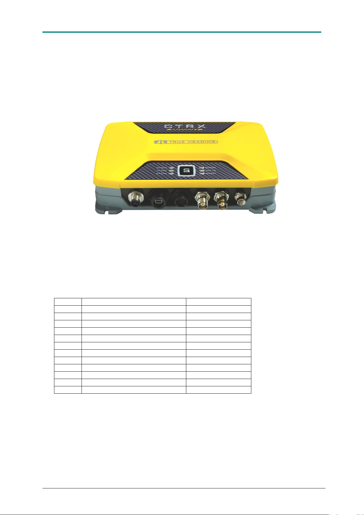
Figure 5 AIS CTRX GRAPHENE + with its antennas and data/DC connectors
The 12 pole multi-pin connector mounted on the transponder has the following configuration
of the pins:
Table 1. Data/DC connector pin configuration
The transponder is secured to the bulkhead or deck by means of four screws. A template for
the fixing of the screws is supplied in the box in the shape of a cardboard divider sheet. The
transponder should be installed so that the six LEDs on the front panel are readily visible for
monitoring of the AIS CTRX GRAPHENE functionality. Furthermore, the transponder may
also be placed for easy access to the "S" – button, which is used to switch the “silent mode”
on and off. Silent mode turns off the transmitter and places the transponder in in receive-
1.9E 14 CTRX GRAPHENE Manual
Page 15

AIS CTRX GRAPHENE Class B AIS Transponder Manual
only mode. A remote switch and LED indicator can be connected to the transponder through
the DC/DATA cable as shown on page 20. A USB connection (mini B-type) is also provided.
For best performance and an easy installation a suitable place should be found were the
installations can provide:
1. Short cable-runs for the VHF and GPS antenna.
2. Easy access to DC power.
3. Access to other equipment to which you may wish to connect the transponder to.
To avoid interference from other equipment on board such as generators, compressors or
electrical panels the unit should not be installed together or close to such equipment.
The accompanying installation software provides a diagnostic program which can be useful
to diagnose a situation where the transponder is experiencing interference. Read more about
this in the”Diagnostics” section in the chapter on the proAIS software.
To ensure that best performance is obtained it is important to choose good antenna cables.
For shorter lengths RG58C/U is sufficient. For cable lengths exceeding 10 m, a low loss
cables should be used, such as type RG213, RG214, or LM400, depending on length. It is
also important to use proper connectors, where crimp type connectors are preferred over
soldered connections. Ready-made 10 m lengths of RG58C/U type cable can conveniently
be used. Ready-made lengths with FME type connectors are available where adaptors for
the different kind of coaxial connectors used can be fitted. In this way an easy-to-assemble
cable/connector kit can be put together for a specific installation without any special tools.
True Heading can provide ready-made kits, cables and connectors.
1.9E 15 CTRX GRAPHENE Manual
Page 16
AIS CTRX GRAPHENE Class B AIS Transponder Manual
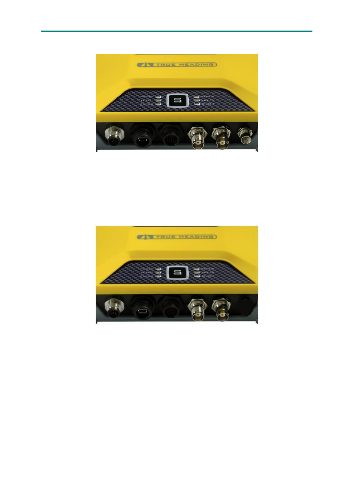
Figure 6. CTRX Graphene+: From L to R: NMEA2000 connector, USB-mini connector, Data/DC
circular connector, GPS antenna (TNC), VHF antenna (BNC) and VHF radio (FME).
Figure 7. CTRX Graphene: From L to R: NMEA2000 connector, USB-mini connector, Data/DC
circular connector, GPS antenna (TNC), VHF antenna (BNC).
After installation of the antennas the AIS CTRX GRAPHENE should be connected to the
equipment where the AIS data from the transponder will be used. AIS CTRX GRAPHENE
has three data ports to choose from, 1 NMEA2000, 1 USB and 1 NMEA 0183.
1.9E 16 CTRX GRAPHENE Manual
Page 17
AIS CTRX GRAPHENE Class B AIS Transponder Manual
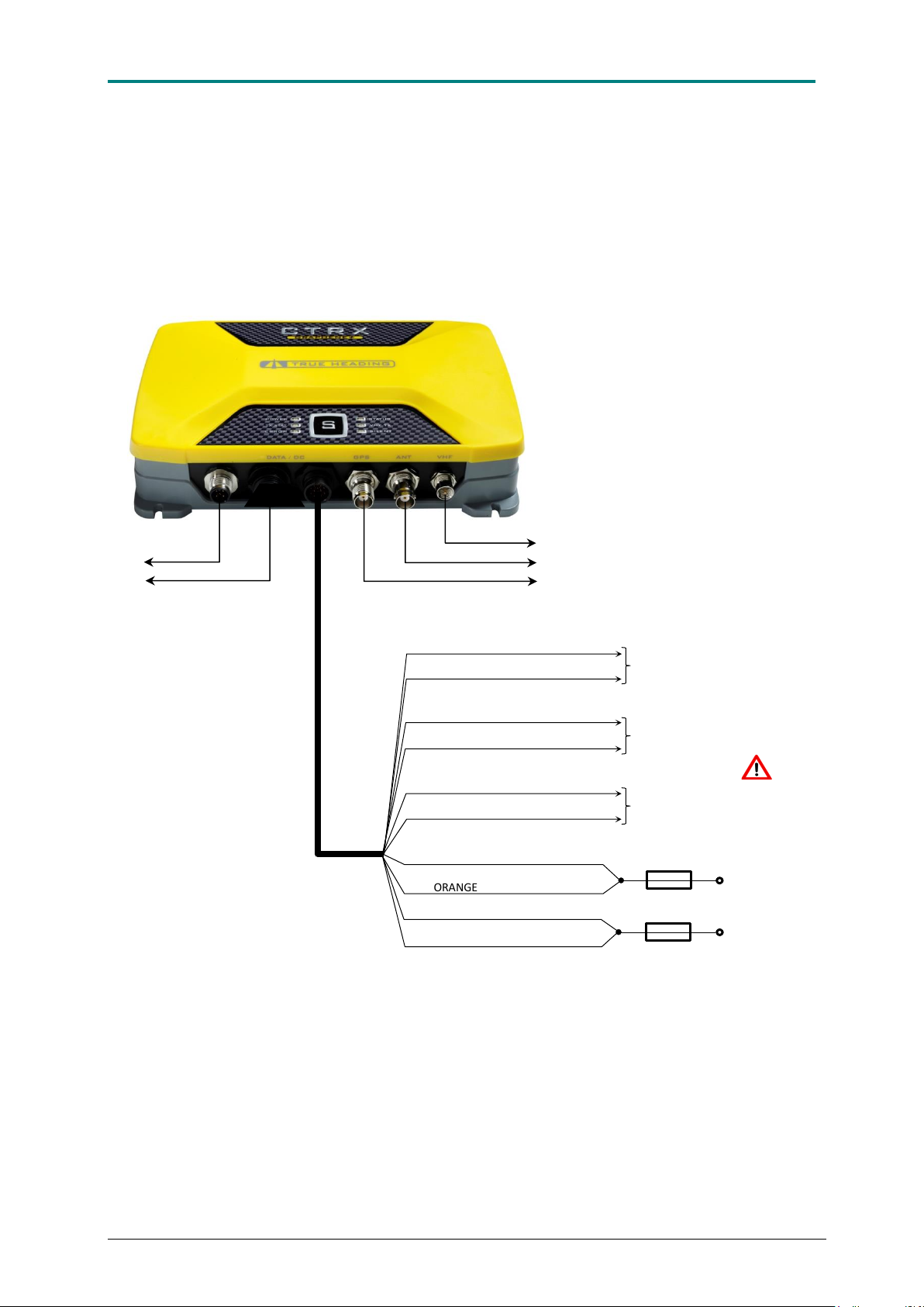
+9-32 VDC Power supply
YELLOW (NMEA OUT Tx-B)
GREY (NMEA OUT Tx-A)
RED
0V DC (Ground)
ORANGE
VHF antenna (BNC)
GPS antenna (TNC)
USB to computer
NMEA2000*
BLACK
BLUE
GREEN
PURPLE
GREEN
WHITE
To external Silent switch
To external LED for Silent switch
DC/Data cable
To VHF radio (Graphene+ only)
To NMEA0183 nav display, e.g. plotter
3A Fuse
3A Fuse
Do NOT apply any
DC voltage to these
wires
CONNECTION, GENERAL OVERVIEW
1.9E 17 CTRX GRAPHENE Manual
Page 18
AIS CTRX GRAPHENE Class B AIS Transponder Manual
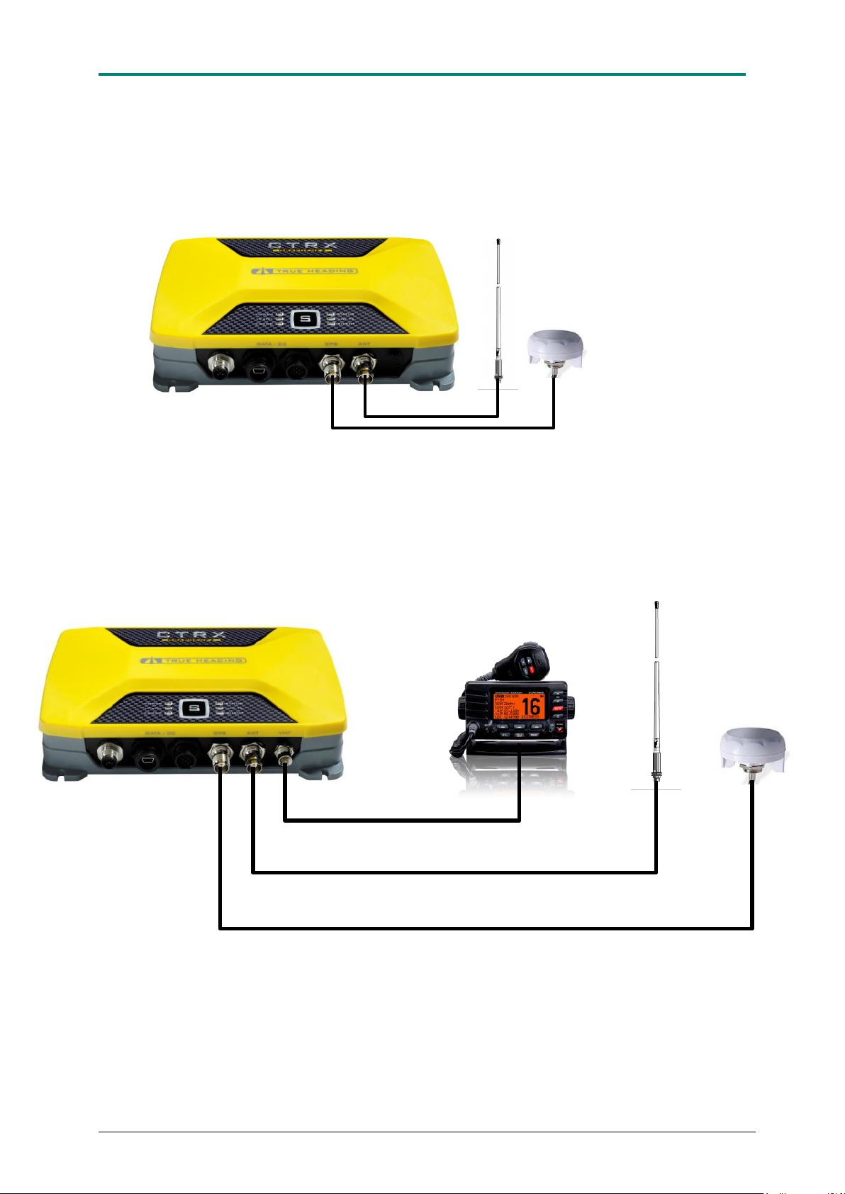
VHF-antenna
E.g. AC Marine CX4
CTRX Graphene
GPS-antenna
CTRX Graphene+
Existing VHF radio
Cable, 5m, RG-58, attached to the GPS antenna
Existing VHF antenna cable in your boat
2m RG-58 cable w/connectors FME & UHF.
GPS-antenna
VHF-antenna
ANTENNA CONNECTIONS
1.9E 18 CTRX GRAPHENE Manual
Page 19
AIS CTRX GRAPHENE Class B AIS Transponder Manual
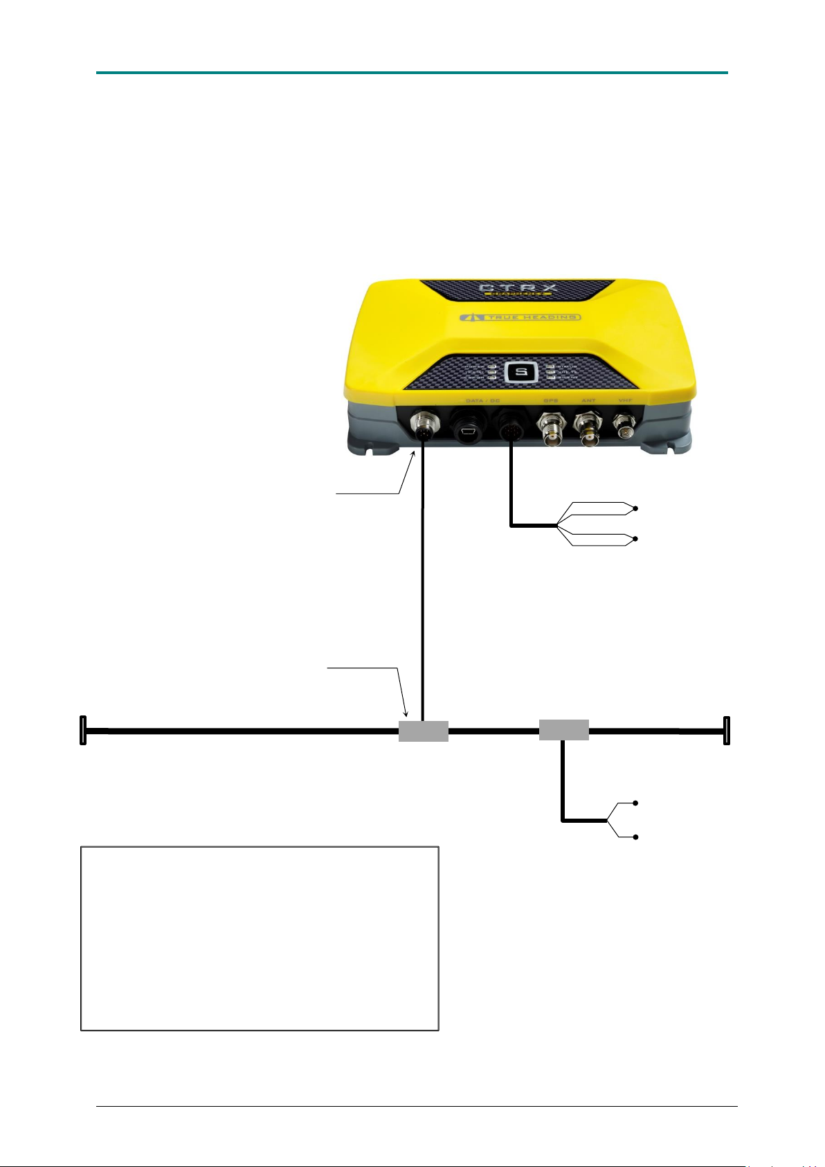
The picture shows the CTRX Graphene+
NMEA2000*
Connection
NMEA2000 T-connection
NMEA2000 Backbone
NMEA2000 Drop cable
Must not be longer than 6m
NMEA2000
End resistor
120 Ohm
9-16 VDC (+)
0 VDC (-)
NMEA2000
Power Tap
9-32 VDC (+)
RED
0 VDC (-)
ORANGE
BLACK
BLUE
NMEA2000
End resistor
120 Ohm
NOTE: The transponder must be connected to an
external power source when connected to an
NMEA2000 network. Even though some
NMEA2000 devices can operate on the bus
power, the transponders current consumption is
higher than the maximum allowed and
subsequently must use external power.
LEN=1 (LEN= Load Equivalence Number)
CONNECTION TO AN NMEA2000 NETWORK
1.9E 19 CTRX GRAPHENE Manual
Page 20
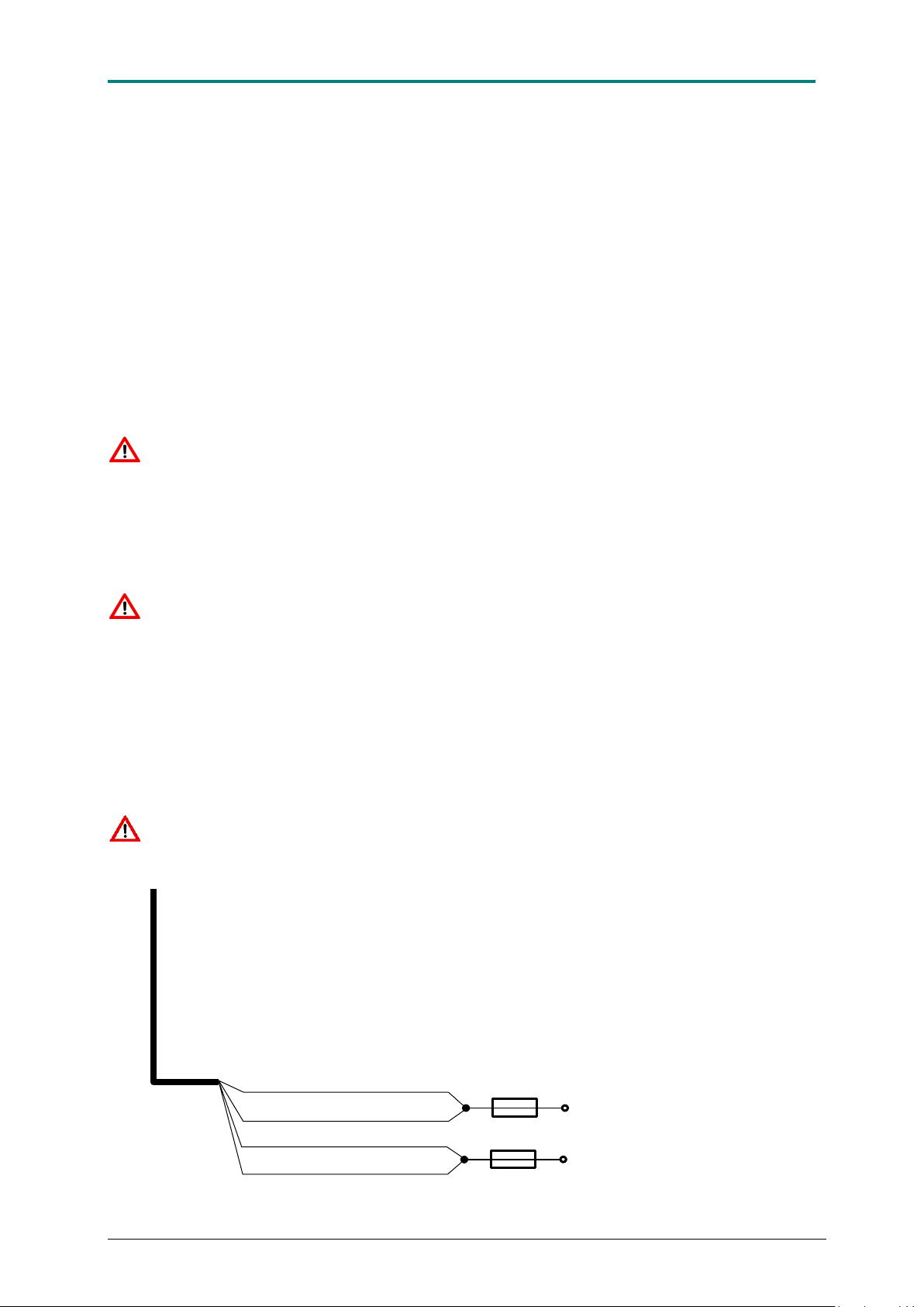
AIS CTRX GRAPHENE Class B AIS Transponder Manual
DC/DATA Cable
RED
ORANGE
BLACK
BLUE
+9-32 VDC Power supply
0V DC (Ground)
3A Fuse
3A Fuse
CONNECTION TO THE DC POWER SUPPLY
Now the connection to the DC power supply is all that is left. The AIS CTRX GRAPHENE
can be connected to any DC power supply providing between 12V to 24V DC. The lower limit
is 10V. Should the supply voltage go below 10V the RED ERROR LED on the front panel will
light up and the unit will cease to transmit. The upper limit is 32VDC. This is the maximum
allowable voltage. If the upper voltage limit is exceeded severe damage will be made to the
transponder.
The DC supply point should be chosen with care. The recommended source should be the
same as the VHF radio and/or other navigational equipment.
Even though the source may be protected with a circuit breaker the transponder must have
its own fuse protection. The recommendation is to use two 3A fuses (one on the positive lead
and one on the negative lead) to provide protection for the transponder.
Note that the negative lead (-) on the transponder is connected to the same point as the
ground on the VHF and GPS antenna connector. This means that if any of the antennas
(VHF or GPS) is bolted to a metal structure on board, can result in a connection to the
negative pole of the power supply (battery). If the unit is installed in a vessel with a metal hull
it is highly recommended that a galvanic isolated DC/DC converter is used between the
battery supply and the transponder to prevent galvanic corrosion or damage to the data
interface.
Note: Be careful not to reverse the polarity of the power supply leads, this may cause
severe damage to the transponder.
The transponder is supplied with a combined Data/DC power cable. The power supply is
connected as follows:
RED and ORANGE cable (twisted together) connects to positive (+)
BLUE and BLACK cable (twisted together) connects to negative (-)
Do not forget the fuses !
1.9E 20 CTRX GRAPHENE Manual
Page 21
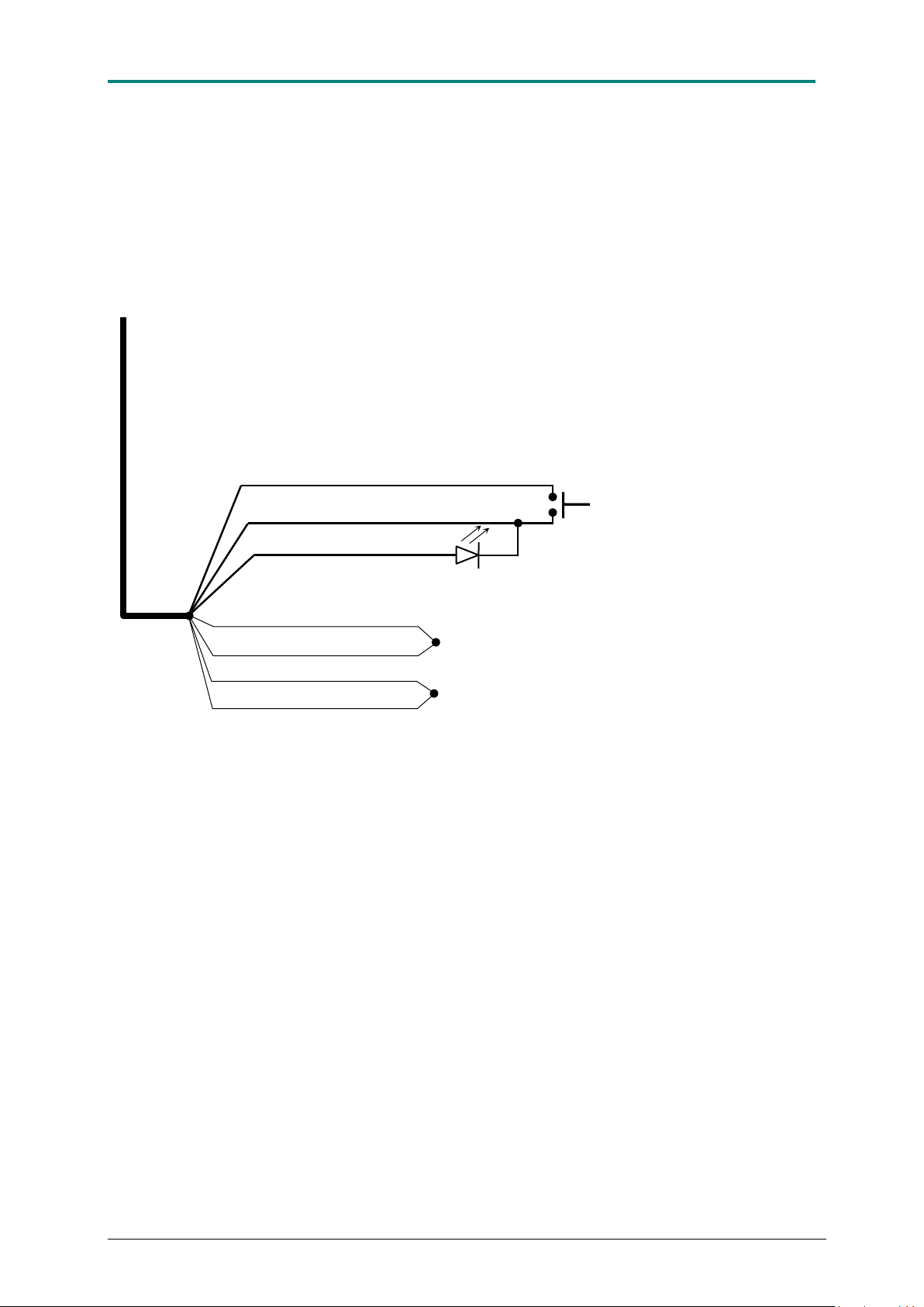
AIS CTRX GRAPHENE Class B AIS Transponder Manual
WHITE
RED
ORANGE
BLACK
BLUE
9-32 VDC
0 VDC
PURPLE
GREEN
Single pole, pushbutton switch
DC/DATA Cable
LED (blue color is recommended)
CONNECTION OF AN EXTERNAL SILENT SWITCH WITH LED
INDICATOR
1.9E 21 CTRX GRAPHENE Manual
Page 22

AIS CTRX GRAPHENE Class B AIS Transponder Manual
PROAIS2 CONFIGURATION SOFTWARE
The proAIS2 application allows you to configure and monitor the performance of your CTRX
Graphene transponder. proAIS2 is compatible with both Microsoft® Windows® and Intel
based Apple® Mac OS operating systems The system requirements are as follows:
Microsoft® Windows® XP, Windows® Vista, Windows® 7 (32 and 64 bit versions)
Mac OS X10.5/10.6 (Intel based system only)
A free USB port for connection to the AIS transponder
Installing the application
The application is installed from the CD provided with your CTRX Graphene transponder.
Insert the CD into your PC or Mac and navigate to the Windows or OSX folder
Windows®
Double click on the “setup.exe” icon to start the installer and follow the on screen
instructions. When installation of the application is completed, installation of the USB driver
will commence automatically.
OS X
Double click on the “proAIS2.dmg” icon to start the installation and follow the on screen
instructions
Connecting to your AIS CTRX GRAPHENE
Before launching the proAIS2 application connect your AIS transponder to your PC or Mac
using a USB cable. Follow the on screen instructions to complete the USB driver installation
if required. You can now launch proAIS2 from the Windows® start menu or the OS X
Applications folder.
When using the proAIS2 program with the transponder, the AIS CTRX GRAPHENE should
be connected using the supplied USB cable. It will be powered from the USB cable during
configuration but cannot transmit or receive AIS messages and the GPS receiver will be
disabled unless connected to a 12V or 24V DC power supply.
If the USB driver fails to install automatically, a USB driver is provided on the CD. Run the
set-up in the USB driver folder to install the driver.
Select the serial port corresponding to your AIS transponder from the drop down menu at the
top left of the proAIS2 window. The port will normally be listed as “AIS Virtual COM Port” and
click on the Connect button.
proAIS2 is now communicating with your AIS transponder and will display any pre-configured
vessel data in the Configuration page.
If the fields are empty the transponder is un-programmed.
1.9E 22 CTRX GRAPHENE Manual
Page 23
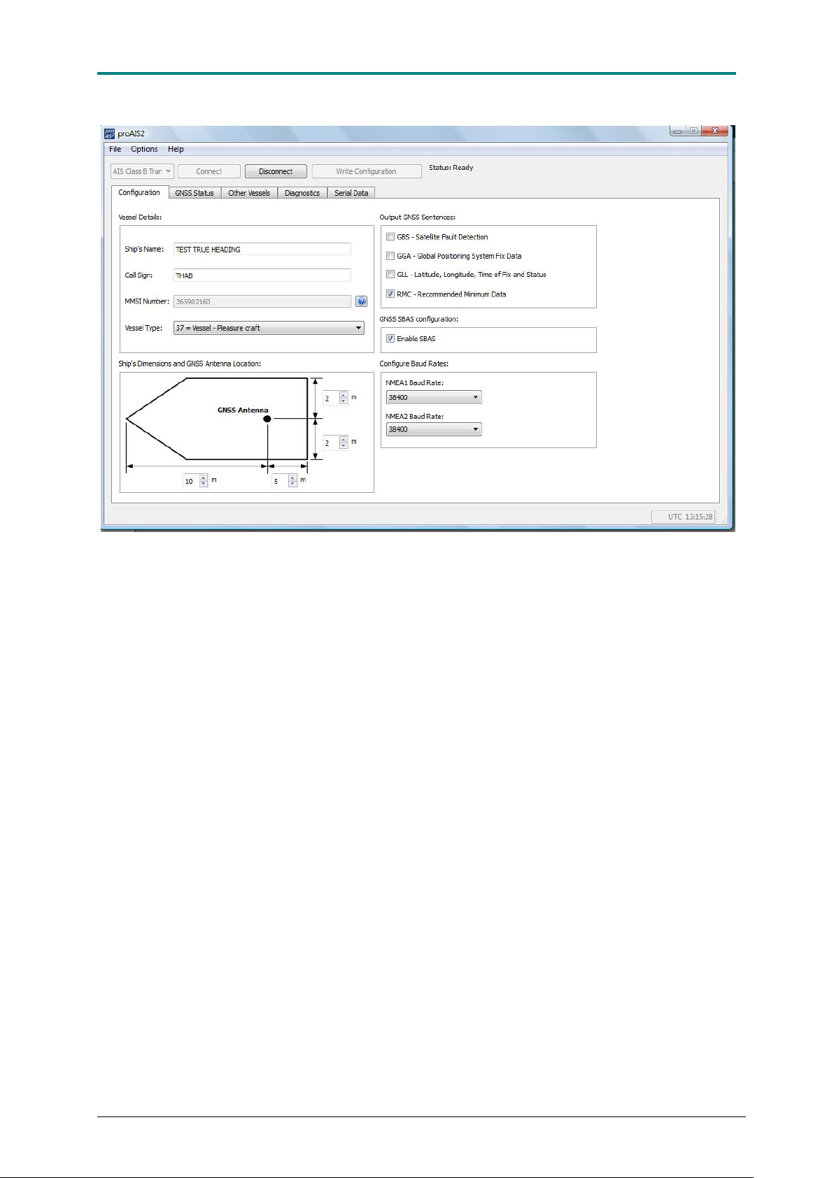
AIS CTRX GRAPHENE Class B AIS Transponder Manual
Figure 15 Connection of PC to AIS CTRX GRAPHENE takes place via choice of the correct port. Normally the correct
port will occur as the first choice stating AIS Class B AIS.
Information on how to configure the unit is given in Appendix A. Restrictions may apply
regarding the configuration of your transponder depending on which country you are a
resident of. Please consult your retailer or contact your Post and Telecom authority.
The Configuration page shows the current vessel information and AIS transponder
configuration. Vessel information and configuration can also be edited and saved to the AIS
transponder
In the Output GNSS Sentences field you can select which type of GPS data you would like
to be output on the data port. The default message set is the NMEA sentence RMC
(Recommended Minimum specific GNSS data) which contains the essential position, course,
speed over ground and time data. GNSS SBAS configuration allows you to select if
DGNSS (EGNOS or WAAS) corrections are to be used or not.
In the Configure Baud Rates window, the baud rate of the NMEA data ports can be
configured. The default setting is 38400 baud which is the common setting for AIS and
should NOT be changed on any of the ports. The NMEA2 port is internal and dedicated to
the optional WiFi interface.
1.9E 23 CTRX GRAPHENE Manual
Page 24
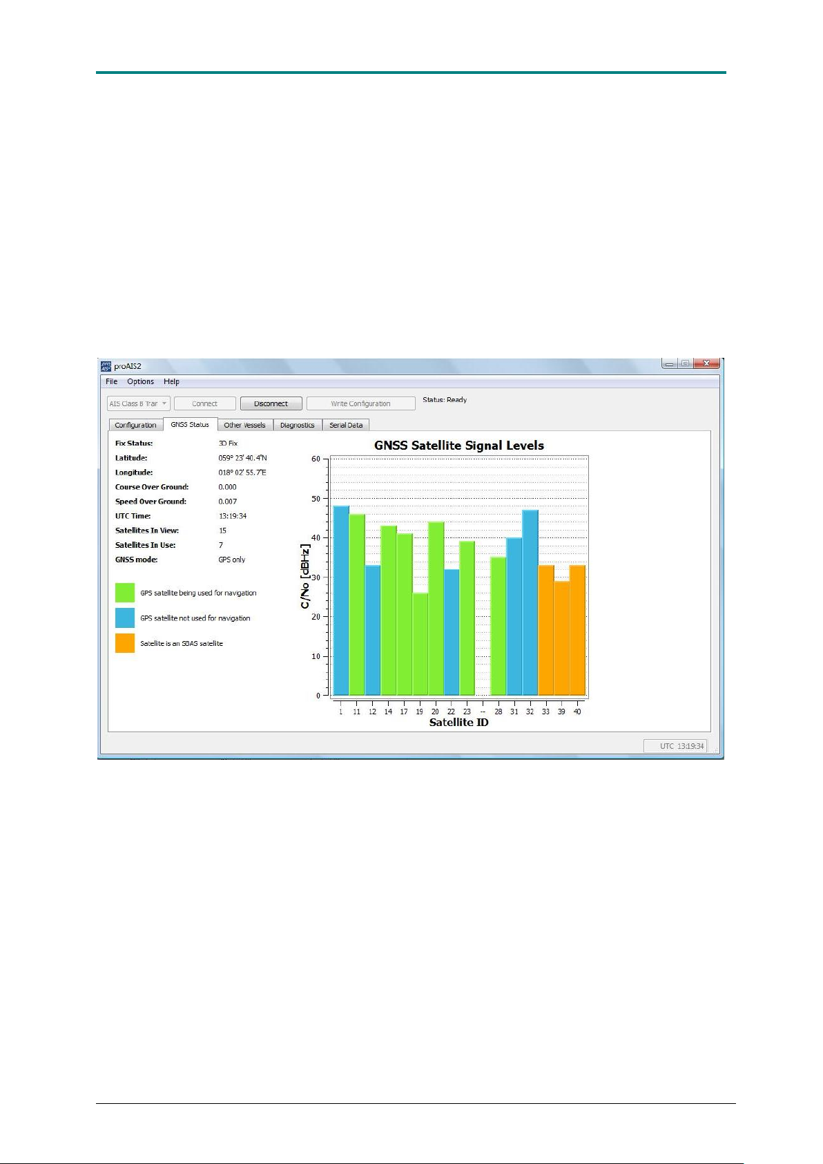
AIS CTRX GRAPHENE Class B AIS Transponder Manual
The next page is the GNSS status page which is a valuable tool for monitoring the built-in
GPS receiver. This tool can conveniently be used during installation to check that the GPS
antenna has been placed in a proper location for reception and that cables and connections
are properly put together and not damaged. When the transponder receives signals from the
satellites a vertical bar will appear representing the received satellite. The bar will change
colour depending on the status of the satellite. When the receiver is locked to a satellite the
bar will change from blue to green indicating that the satellite is used for navigation. If SBAS
is used the satellites involved in tracking the SBAS data will show up in yellow.
The reception quality is displayed as a C/N value (carrier to noise), which means that the
higher the value, the better the signal quality is. A mean value for a reasonable reception
quality should be not less than 30 dBHz.
Figure 16 AIS CTRX GRAPHENE GNSS Status field showing satellites being used as well as not being used plus
DGNSS satellites using SBAS.
1.9E 24 CTRX GRAPHENE Manual
Page 25
AIS CTRX GRAPHENE Class B AIS Transponder Manual
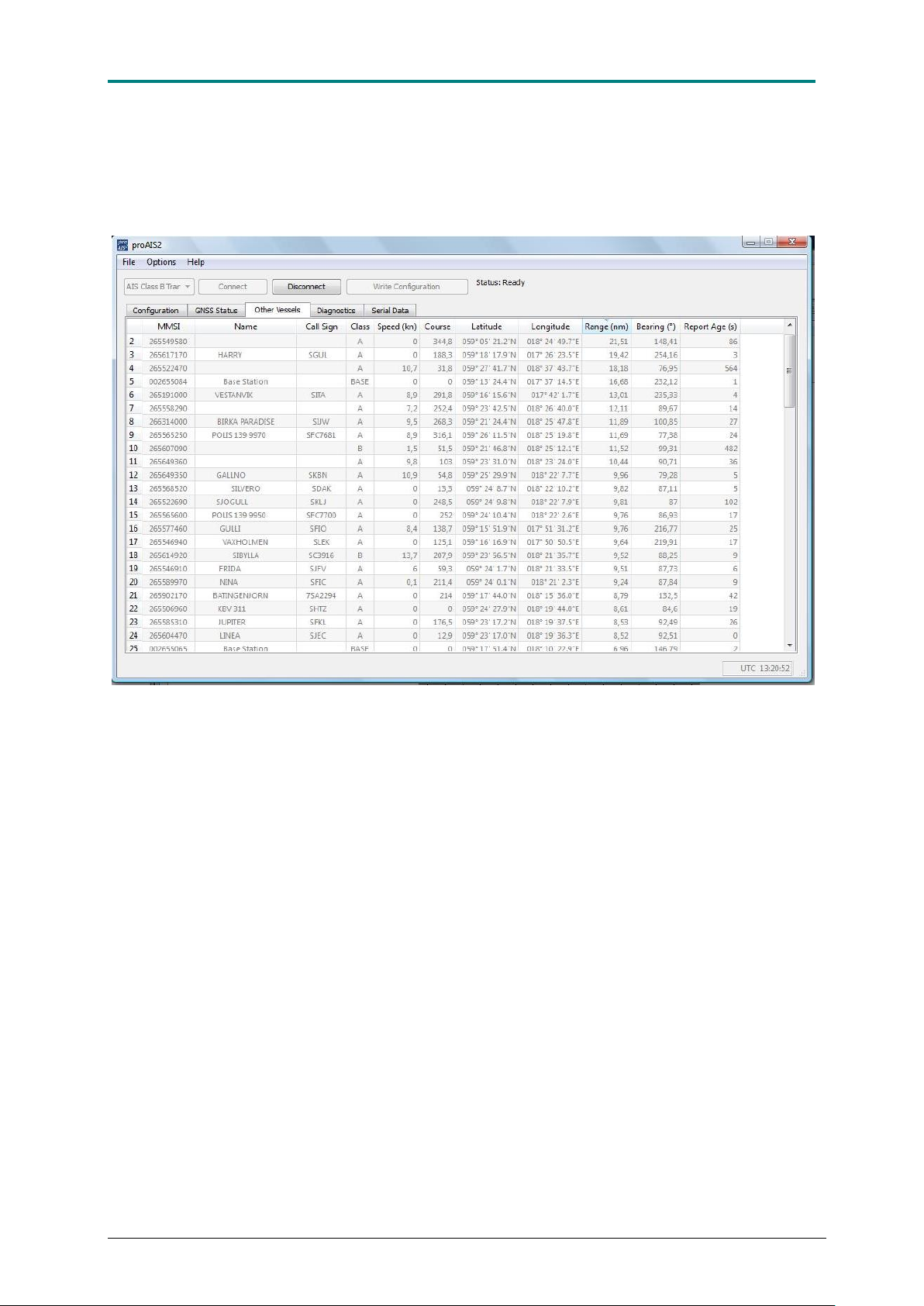
The Other Vessels page provides you with an easy way to check that your AIS CTRX
GRAPHENE receives data from other AIS transponders. By clicking on the column label the
data field can arrange in falling or increasing order depending on the column of interest.
Figure 17 In the [Other Vessels] field, information is present about all AIS units that can be seen by the connected AIS
CTRX GRAPHENE transponder.
1.9E 25 CTRX GRAPHENE Manual
Page 26
AIS CTRX GRAPHENE Class B AIS Transponder Manual
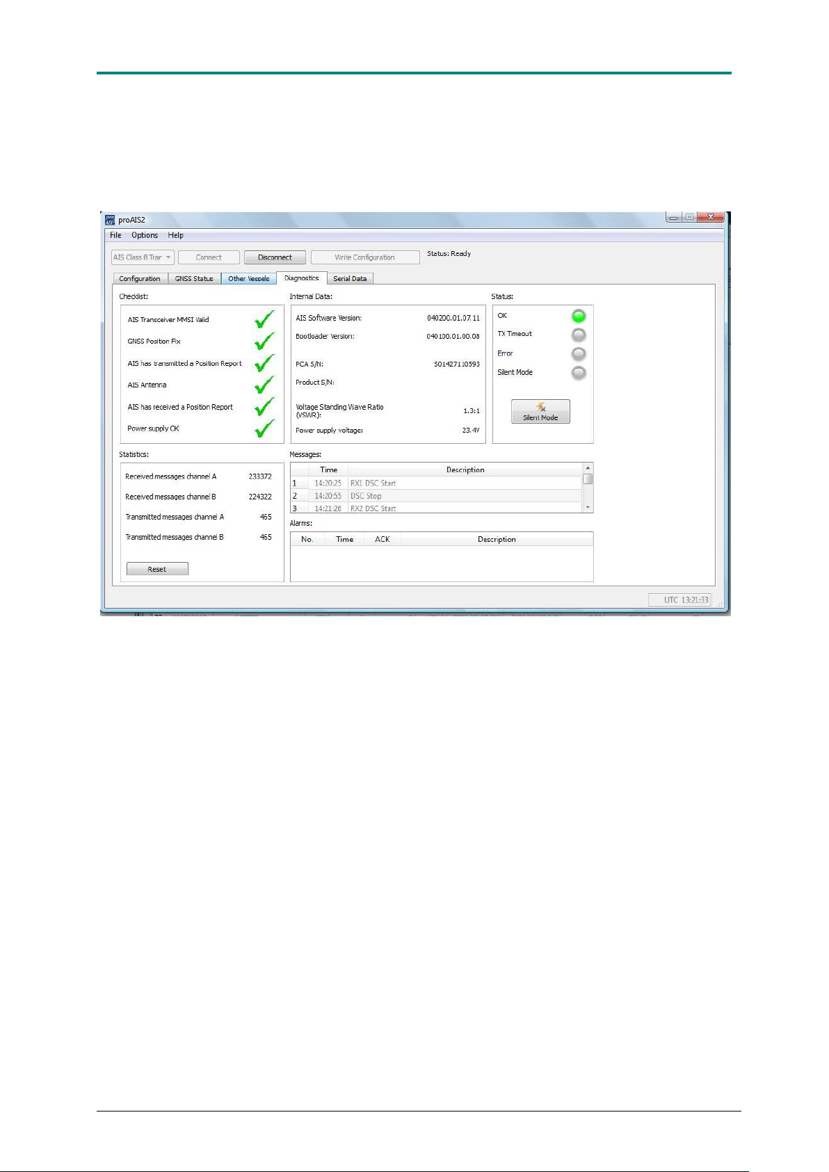
The Diagnostics page has several functions and tools to check that your AIS transponder
works properly. The tools make it easy to monitor and check performance during and after
installation.
Figure 18 AIS CTRX GRAPHENE Diagnostics field provides good information about the transponder's status and the
software version.
In the window Checklist, you can get an overall view of the main functions of the
transponder such as:
Programming (Transponder MMSI valid)
GPS functionality (GPS Position Fix),
Transmission (AIS has transmitted a position report)
Antenna function (AIS antenna),
Reception (AIS has received a report)
Power supply (Power supply OK).
Once the items have a green tick the function is checked and validated.
The Internal data window shows the version of the firmware and boot loader as well as the
product code and internal serial number. The serial number is the same as on the bottom
label and should be referred to should it be necessary to contact True Heading for support.
Also the VSWR value (antenna matching factor) is shown here as well as the power supply
input voltage.
The Status window show the status of the LED’s on the front panel. Normal operation should
have the green LED light. Once in a while, depending on the operational situation (AIS traffic
load) the status may change to yellow, which means that the transponder has not been able
to transmit during the last transmission period. Once the units have transmitted the LED
lights will go back to green.
1.9E 26 CTRX GRAPHENE Manual
Page 27

AIS CTRX GRAPHENE Class B AIS Transponder Manual
Before the AIS CTRX GRAPHENE has been programmed, both the yellow and red LED’s
will light, indicating that the unit is not programmed (no valid MMSI number). This is shown
both on the transponder and on the status panel in proAIS2
The green Power LED on the transponder panel indicates that the transponder is connected
to a DC supply and powered on.
The red Error LED indicates the following errors:
• The transmitter has transmitted longer than 1 s.
• The GPS has not started to navigate after 30 minutes
• Excessive VSWR value (> 3:1) (faulty antenna or cable problem).
• Faulty transmitter (no or low power output).
• A severe fault which prevents normal operation
The yellow TX timeout LED will turn on to indicate a change in the operating status. The
situation has called for the transmitter to stop transmitting.
The yellow TX timeout LED can indicate the following conditions:
• The transponder GPS has not received a position fix which means that the
transponder cannot transmit as the position data is invalid.
• The GPS receiver is waiting to acquire a position fix (LED is flashing)
• The transponder has not been able to transmit because free slots are not available.
This can be due to disturbance from radio and/or electrical equipment on board or the
AIS traffic situation (many transponders in the same area).
When the situation has been resolved the yellow LED will turn off and the green status LED
will be turned on (on the front panel of the transponder). This is the normal operating
condition.
The blue Silent Mode LED will light up when AIS CTRX GRAPHENE is set in silent mode,
which turns off the transmitter. This sets the transponder in receive-only mode. This is
referred to as ”SILENT MODE”.
The transponder can be switched to SILENT mode by either pressing the “S” button on the
front panel for 3 seconds or by using an external switch (see page 21 for wiring instructions)
To switch off the SILENT mode hold the “S” button down for 3 seconds. The blue LED will
turn off after approximately 1 second.
A third way to switch the unit to SILENT MODE is to use the software button (marked Silent
Mode) in proAIS2 status window were the function can be remotely switched on and off.
NOTE that this is a special function in proAIS2 and that it is separate from the hardware
control to set the silent mode with the switch.
In the Statistics window received and transmitted messages on the two channels is shown.
The values are accumulated from the time the transponder was connected up to the proAIS
program. The values will be reset as soon as the connection is disconnected.
1.9E 27 CTRX GRAPHENE Manual
Page 28
AIS CTRX GRAPHENE Class B AIS Transponder Manual
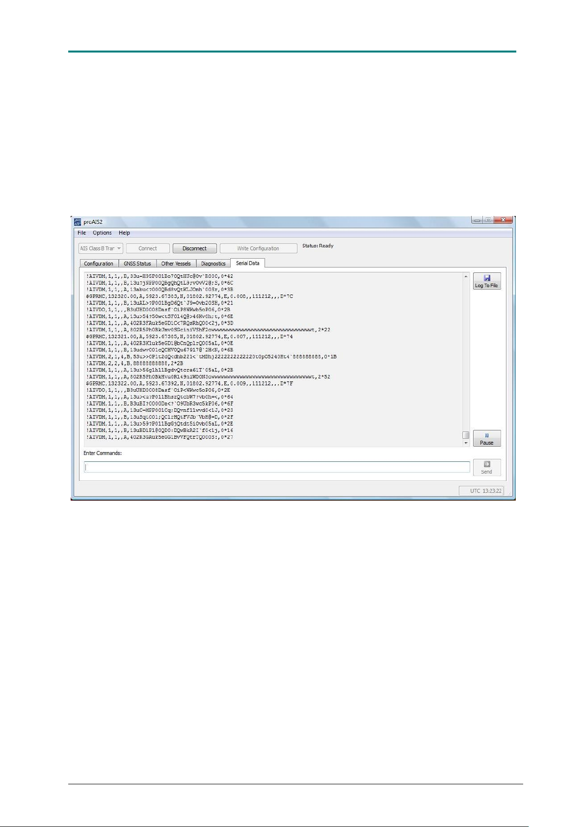
The Serial data page is for the more experienced installer. The page offers a valuable tool
for monitoring the data output from the transponder. Data is output in NMEA0183 format.
Received data will appear as !AIVDM strings, transmitted data as !AIVDO and GPS data as
$GPRMC (or any of the GPS data sentences selected). The field Enter commands below
the data window is used for input data to the transponder. This field is only used for
diagnostics and service functions.
The data shown in the window can be logged and recorded in file format for later recovery
and analysis.
Figure 19 In the field Serial data the data the transponder transmits is displayed on its port and from this data,
important information can show that the transponder functions correctly.
1.9E 28 CTRX GRAPHENE Manual
Page 29

AIS CTRX GRAPHENE Class B AIS Transponder Manual
NOTES
1.9E 29 CTRX GRAPHENE Manual
Page 30
AIS CTRX GRAPHENE Class B AIS Transponder Manual
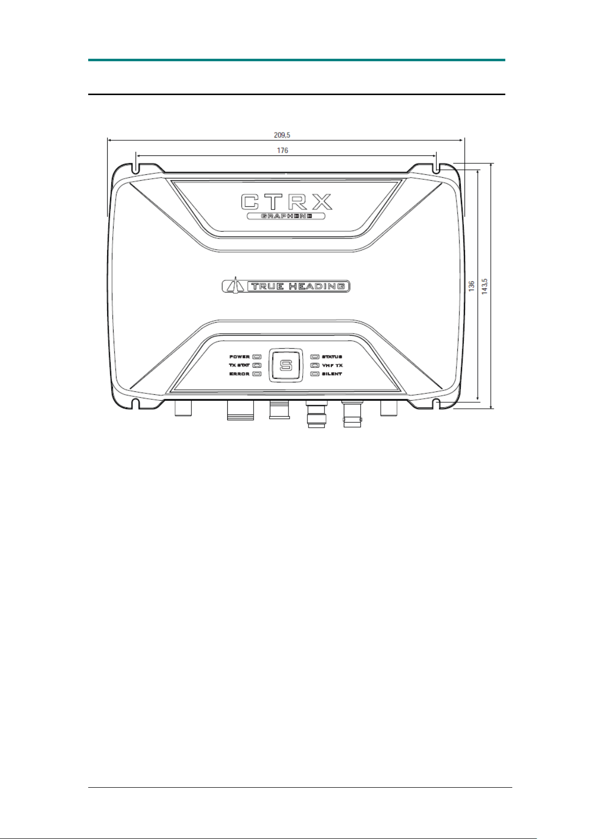
Mounting Template
NOTE: NOT drawn to scale!
1.9E 30 CTRX GRAPHENE Manual
Page 31
AIS CTRX GRAPHENE Class B AIS Transponder Manual
APPENDIX A CONFIGURING THE AIS CTRX GRAPHENE
AIS CTRX GRAPHENE is configured using the proAIS2 software supplied with the
transponder. proAIS2 runs on Windows XP (SP2), Windows Vista and Windows 7 &
8. A version for MacOS is also available on the product CD.
The following information is needed to configure your AIS CTRX GRAPHENE:
1. Assigned MMSI number (9 characters)
2. Call sign (7 characters maximum)
3. Vessel’s name: (20 characters maximum)
4. Vessel type (ex. 37 Pleasure craft)
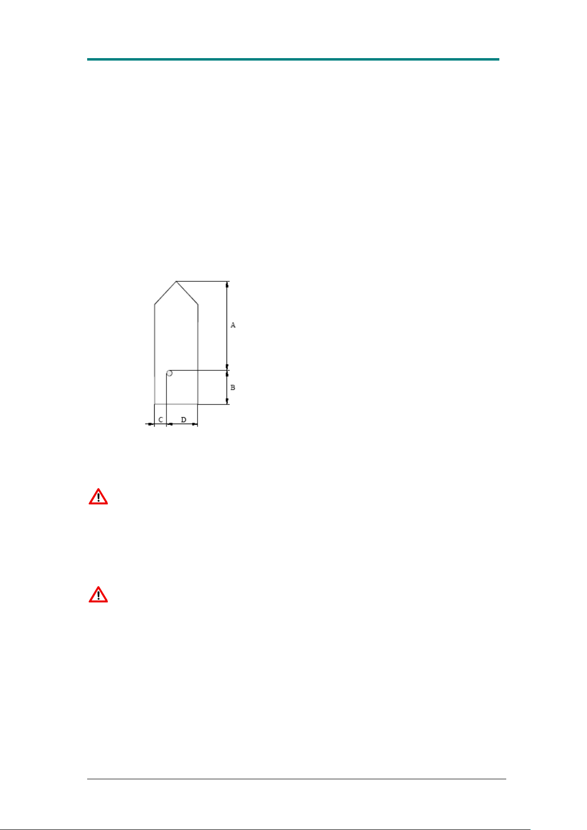
5. GPS antenna position
Table 6 Ships dimension (GPS reference position)
Important information for US Customers:
There are specific laws in the USA regarding the configuration of AIS class B
transceivers. If you are a US resident and intend to use your AIS class B transceiver
in US waters, you should make sure that your retailer has configured your product
prior to supplying it to you. If your AIS transceiver has not been pre-configured
please contact your dealer for details of how to have it configured.
WARNING:
It is a violation of the rules of the Federal Communications Commission to
input an MMSI that has not been properly assigned to the end user, or to
otherwise input any inaccurate data in this device.
1.9E 31 CTRX GRAPHENE Manual
Page 32

AIS CTRX GRAPHENE Class B AIS Transponder Manual
To configure the transponder proceed as follows:
Start the proAIS2 application and select the serial port corresponding to the AIS
transponder from the drop down menu at the top left of the proAIS2 window. Select
the Configuration page and enter your vessel’s data:
1. Enter vessel’s name (use only A-Z and –, max. 20 characters)
2. Enter vessel’s call sign (max. 7 characters)
3. Enter the assigned MMSI number (max. 9 characters)
4. Select Vessel type (the type of vessel on which the transponder is installed
on). We recommend that all types of leisure craft is set as 37 = Vessel -
Pleasure craft.
5. Enter the Ship dimensions which are determined by the position of the GPS
antenna. The length of the vessel is set by the distance measured from fore
to the GPS antenna (A) and from aft to GPS antenna (B). The beam is
measured as the distance from starboard to the GPS antenna (C) and from
port to the GPS antenna (D). The values should be entered in meters,
rounded up to the nearest meter.
When finished click on Write Configuration and follow the on screen instructions.
Before data is stored you will be prompted to make sure that the data is correct
before you can proceed to write the data permanently. This is the last chance to
correct any errors, so make absolutely sure that MMSI, name and call sign are
correctly entered in their respective fields before you press the button.
Once the MMSI number is programmed it cannot be changed!
Should the transponder been programmed with an incorrect MMSI, please contact
True Heading support.
1.9E 32 CTRX GRAPHENE Manual
Page 33

AIS CTRX GRAPHENE Class B AIS Transponder Manual
APPENDIX B ANTENNAS AND ANTENNA MOUNTING
GPS Antenna
The GPS antenna used must be of the active type (i.e. it should incorporate an LNA) and
must be suitable for marine shipboard applications (index of protection, ruggedness, means of
mounting, etc.). An antenna should be selected with a gain (in dB) depending on the length
of cable between the antenna and the AIS unit; after subtraction of cable and connector
losses a minimum total gain of 25 dB should be available at the AIS CTRX GRAPHENE unit
GPS antenna connector.
The GPS antenna to be used for AIS use must be a dedicated antenna, i.e. not shared with
any other GPS receiver.
Installation of the GPS antenna is critical for the performance of the built in GPS receiver
which is used for timing of the transmitted time slots and for the supply of navigational
information should the main navigational GPS fail. We strongly recommend that:
1. The GPS antenna is mounted in an elevated position and free of shadow effect from
the ship’s superstructure
2. The GPS antenna has a free view through 360 degrees with a vertical angle of 5 to 90
degrees above the horizon.
3. As the received GPS signal is very sensitive to noise and interference generated by
other on board transmitters, ensure that the GNSS antenna is placed as far away as
possible from radar, Inmarsat and Iridium transmitters and ensure the GPS antenna is
free from direct view of the radar and the Inmarsat antenna beam.
4. It is also important that the MF/HF and other VHF transmitter antennas are kept as far
away as possible from the GNSS antenna. It is good practice never to install a GNSS
antenna within a radius of 5 Metres from these antennas.
VHF antenna for AIS use
The VHF antenna employed for AIS use:
Must be a dedicated antenna, i.e. not shared with any other VHF transmitter/receiver.
Must be suitable for marine shipboard applications (index of protection, ruggedness,
means of mounting, etc.)
Should be omni-directional and vertically polarised with unity gain (0 dB) and with a
bandwidth sufficient to maintain a VSWR less than 1.5 over the frequency range 156
– 163 MHz. As a minimum the 3dB bandwidth must cover the two AIS channels and
the DSC Channel 70.
Should be mounted with at least a two meter vertical separation distance from any
other VHF antenna used for speech or DSC communication. See EMI warning below.
Should be mounted at least 2-3 metres above sea level for good performance.
1.9E 33 CTRX GRAPHENE Manual
Page 34

AIS CTRX GRAPHENE Class B AIS Transponder Manual
Object
Safe distance
Radar antenna, X-band
1, 5 m (5 ft)
High efficiency engines
1 m (3 ft)
HF or VHF antennas
3 m (10 ft)
AC power cables with high currency
1 m (3 ft )
Satellite communication antennas
4 m (13 ft)
WARNINGS
VHF Antenna
Connecting a badly mismatched VHF antenna, leaving the VHF antenna port disconnected,
or shorting the VHF antenna port will activate the VSWR alarm, causing the unit to stop
transmitting to prevent damage to the transponder. The red LED will light up indicating an
error preventing normal operation.
EMI (Electro Magnetic Interference) from other equipment on board
To ensure proper functionality it is necessary to install the VHF antenna correctly and operate
the AIS equipment according to the instructions.
The table below shows suitable safe distances to other equipment that could cause
interference to the AIS Class B Transponder.
1.9E 34 CTRX GRAPHENE Manual
Page 35
AIS CTRX GRAPHENE Class B AIS Transponder Manual
APPENDIX C WIFI OPTION
The CTRX Graphene transponder can be fitted with WiFi connectivity as an option.
The WiFi unit is built-in and has an integral antenna.
The WiFi option provides a possibility to connect and share AIS data with a wireless
device such as a tablet or a laptop computer. The WiFi is set up as an access point
which provides connectivity using the choice of TCP or UDP protocol.
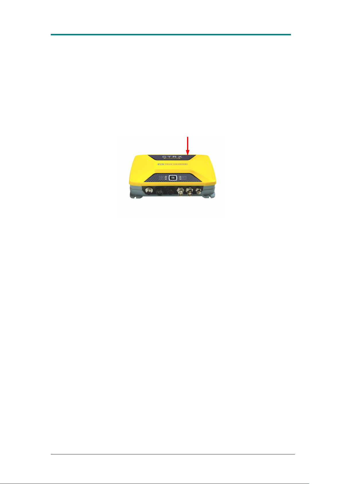
The WiFi antenna is installed on the inside of the bottom part of the enclosure (see
arrow). When installing the CTRX Graphene WiFi, please make sure that this area is
kept away from any metallic parts such as bulkhead etc. which can attenuate the
signal from the WiFi unit.
WiFi antenna position
Technical data
Type: RN-171-XV
Frequency range: 2,402 – 2,480 MHz
Modulation standard: 802.11 b/g
Channels: 1 – 14
Transmission rate: 1-11 Mbps for 802.11b / 6-54 Mbps for 802-11g
Output level: Class 1 (up to +12dBm)
Settings
Protocol used: TCP and UDP
SSID: Trueheadingxxxx (xxxx is the transponder serial
number)
TCP
IP address: 192.169.78.1
Port: 2000
UDP
Broadcast address: 192.168.78.255
Port: 2000
Note: The settings are fixed and cannot be changed by the user.
1.9E 35 CTRX GRAPHENE Manual
Page 36

AIS CTRX GRAPHENE Class B AIS Transponder Manual
PGN
description
PGN number
Comments
Class A
Position
Report
PGN129038
Class B
Position
Report
PGN129039
AIS UTC and
Date report
PGN129793 output
From AIS message #4 base
station messages
AIS Class A
Static and
Voyage
Related Data
PGN129794
AIS SAR
Aircraft
Position
Report
PGN 129798
AIS Broadcast
Safety
Message
PGN129802
AIS Class B
static data part
A
PGN129809
AIS Class B
static data part
B
PGN129810
AtoN position
report
PGN129041
NMEA2000
group function
PGN126208
NMEA2000
product info
PGN126996
ISO request
PGN059904
ISO
Acknowledge
PGN059392
ISO address
claim
PGN060928
ISO Address
command
PGN 065240
GPS position,
rapid update
PGN 129025
Added in V1.7
COG and
SOG, rapid
update
PGN 129026
Added in V1.7
APPENDIX D CTRX GRAPHENE NMEA 2000 PGN LIST
1.9E 36 CTRX GRAPHENE Manual
 Loading...