

True Fitness TREADMILL 2011 Service Manual
Proprietary & Confidential
TRUE Fitness Technology, Inc.
2011 TREADMILL
SERVICE MANUAL
Proprietary & Confidential
TRUE Fitness Technology, Inc.
Proprietary & Confidential
TRUE Fitness Technology, Inc.
b. A service technician trained on comparable fitness equipment, currently
employed as a fitness equipment technician and experienced with the hazards
involved with its installation, operation and maintenance.
Tread Service Manual - July 2011
2

Proprietary & Confidential
TRUE Fitness Technology, Inc.
Proprietary & Confidential
TRUE Fitness Technology, Inc.
SYMPTOM GUIDE
Diagnostics……………………………………5-8
Drive System Overview………………………..9
Elevation System Overview………………10-12
Error Codes
Definitions………………………………13-14
E1 Stall/ E1 Range...…………………..15-16
E2 Cal…………………………..…….…….17
E5 Sensor………………………………18-22
Misc Symptoms
No Console Display…………………...23-24
No/ Erratic Heart Rate…………………....25
No Fan……………………………………. .26
No Safety Key Detected………………….26
No Sound/ Channels on Wireless……….26
No Response Touchscreen Keys….…….27
Touch Screen Will Not Function…………28
No IPOD detected……………………...…29
No TV/ Poor Quality……………………....29
TEST PROCEDURES
Amp Draw Test………………………………..30
Speed Sensor Test……………………………31
Potentiometer Test………………………..32-34
Voltage to Incline Motor Test………………....35
Table of Contents
3
Tread Service Manual - July 2011

Proprietary & Confidential
TRUE Fitness Technology, Inc.
Proprietary & Confidential
TRUE Fitness Technology, Inc.
Test Procedures(cont.)
Push Off Test …………..................................36
Running Belt Tension Test …………………..37
Care and Maintenance
Running Belt Alignment……………………....38
Lubrication Instructions………………………39
General Maintenance………………………..40
Appendix A: AC Lower Board LEDs
General LEDs……………………………...41-42
Status LEDs………………………………..43-46
Appendix B: Smart Card LEDs………….……......…..47
Appendix C: Calibration………………………………..48
Appendix D: TV tuner Set-Up……………..……….49-51
Appendix E: Wireless Card Set-up…………….….52-53
Appendix F: Universal Console Model Config…...54-55
Appendix G: Software Installation
15” Touchscreen……………………………56-58
11” and 2-Window ………………………….....59
Table of Contents
4
Tread Service Manual - July 2011

Proprietary & Confidential
TRUE Fitness Technology, Inc.
Proprietary & Confidential
TRUE Fitness Technology, Inc.
5
2 WINDOW DISPLAY
Press CLEAR ENTRY until the screen blanks then press hold
ENTER. [ or Hold speed Up () Key while inserting safety key ]
A. Input 10101 (Basic Mode) B. Input 20173(Service Mode)
1. Units (English)
2. Max Time (99)
3. Default Time (30)
4. Reset (60 sec)
5. Sound (On)
6. Default Weight (150)
7. DM LC Backlight (45)
8. DM Contrast (40)
9. MC Backlight (9)
10. MC Contrast (35)
11. HR Priority (0)
12. C-Safe Enable (Disabled)
13. Reset Model Def (not used)
14. Error Log 1-5
1. Version
2. Hours
3. Distance
4. Program Starts
5. Display Test
6. HR Test
7. B Light Test
8. Contrast Test
9. LCB Control Test
10.CS/BV Test
11. Smartcard/Motor Board
12.Remote Key Test
13.Current Test(RPM only)
14.Safe Switch Test
15.Program Usage
16.BV Setup
17.Watch Dog Test
To exit : Press Start –
Watch Dog Test will count
down & system will clear
Tread Service Manual - July 2011
Proprietary & Confidential
TRUE Fitness Technology, Inc.
Proprietary & Confidential
TRUE Fitness Technology, Inc.
6
A. press 10101 (Manager Mode)
1. Hours
2. Distance
3. Units
4. Max Program Time (99)
5. Def Program Time (30)
6. Reset Time (30)
7. Audible Sound (On)
8. Def Weight (150)
9. Cool Down (Disable)
10. Contrast (160)
11. Left BK LT (63)
12. Right BK LT (63)
13. HR Priority (Tele)
Error Log 1-5.
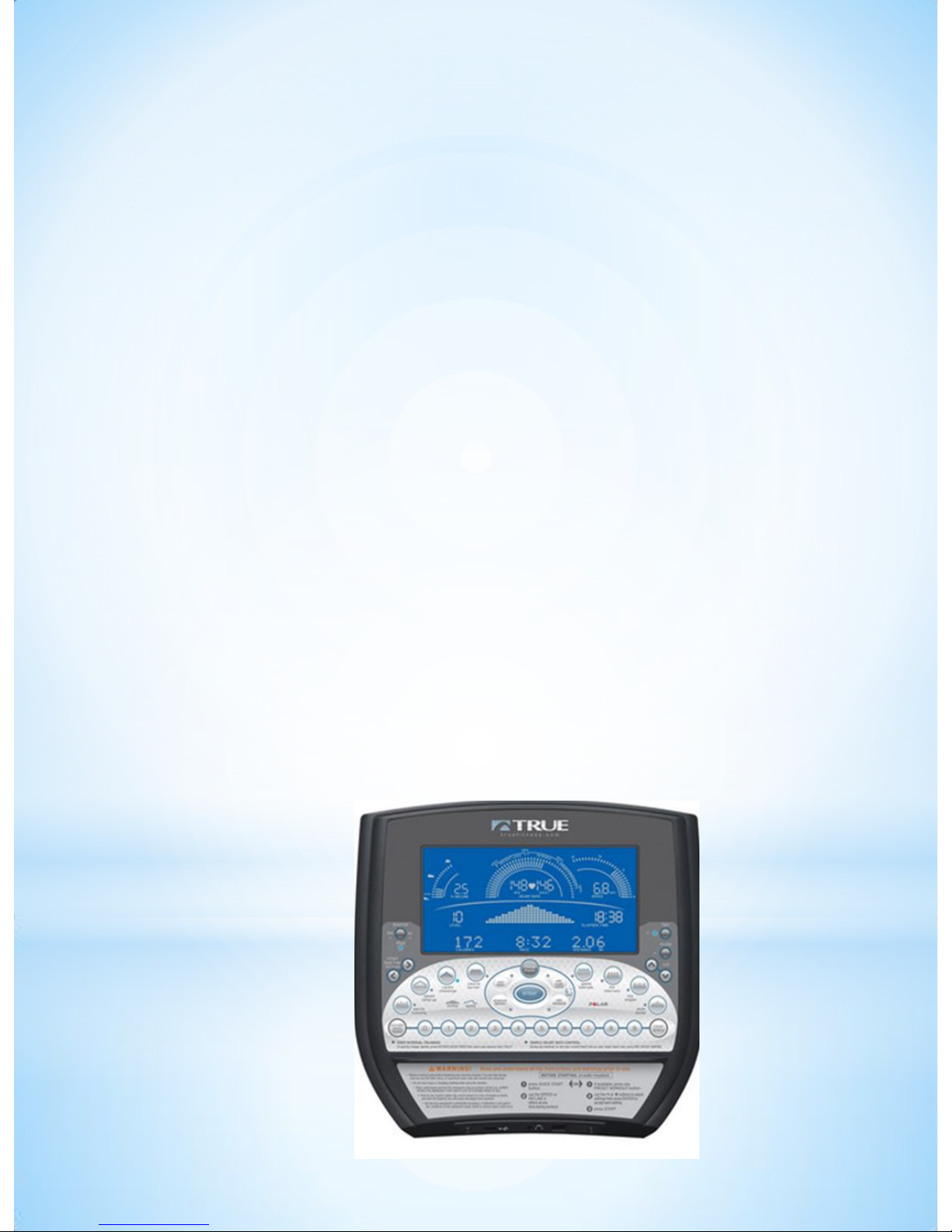
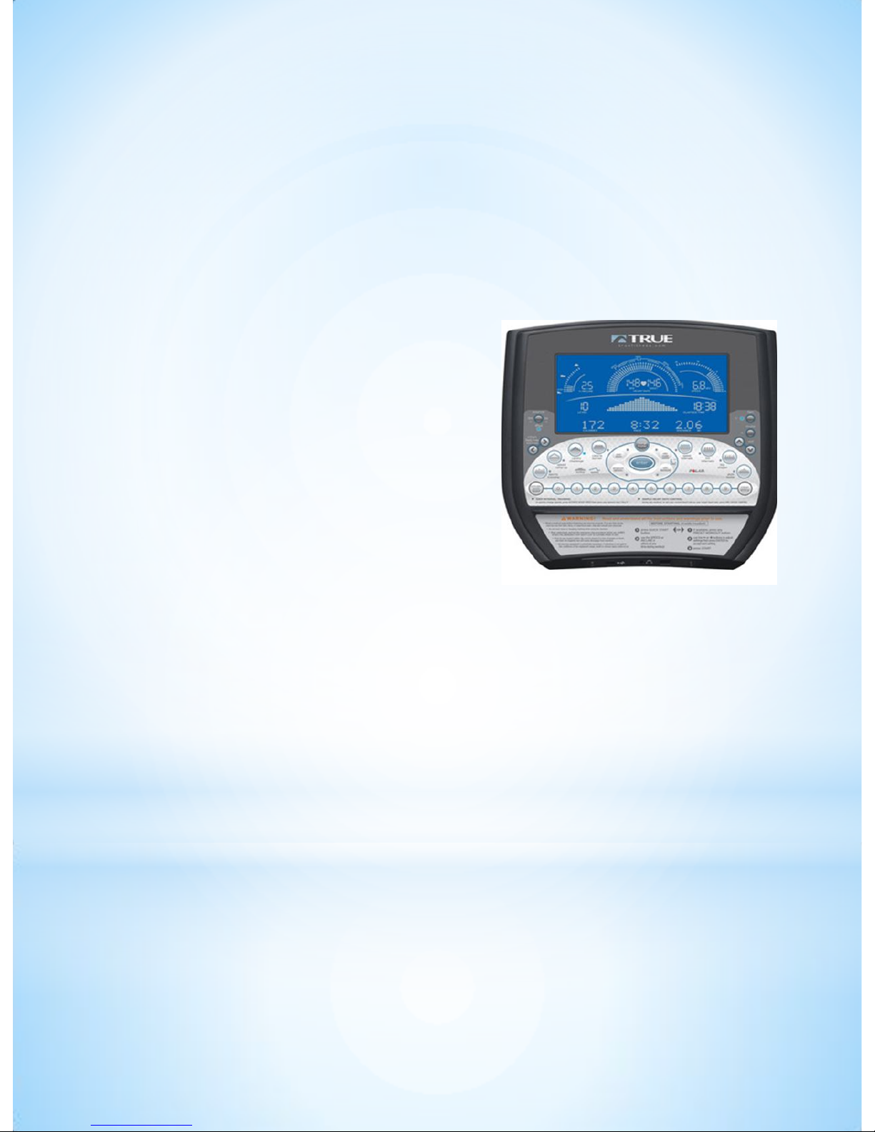
11” WINDOW DISPLAY
Press CLEAR ENTRY until the screen blanks then press
and hold ENTER:
B. Press 20173 (Service Mode)
1. Version Test
2. Checksum #
3. Display Test
4. Keyboard Test
5. HR Test
6. LWR CNTL BD Test
7. LCD Settings Test
8. Aux Board Test
9. Vart Test
10. Safe SW Test
11. BV Setup
12. Watch Dog Test
Tread Service Manual - July 2011
Proprietary & Confidential
TRUE Fitness Technology, Inc.
Proprietary & Confidential
TRUE Fitness Technology, Inc.
7
C. Press 48362 (Configuration Mode)
1. Model
2. Max Speed
3. Max Grade
4. Hours
5. Distance
6. LCD Contrast
7. Left Backlight
8. Right Backlight
9. HR
10.Elevation Cal
11.Gear Ratio
12.Grade Max %
13.Cool Down
14.Max Program Time
15.Default Program Time
16.Reset Time
17.Language
11” WINDOW DISPLAY (cont.)
Tread Service Manual - July 2011
Proprietary & Confidential
TRUE Fitness Technology, Inc.
Proprietary & Confidential
TRUE Fitness Technology, Inc.
8
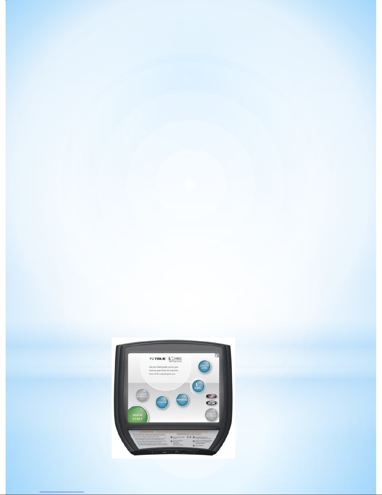
15” Touch Screen
The Maintenance Mode is designed to help the tech
determine certain faults in the upper control boards
and feedback from the brake system.
Press and hold the top left corner of screen until the
True emblem will begin to flash after 4 seconds.
Press and hold Manual Workout Button to reveal list
of options
1.Configure (Displays the current model setup)
2.Calibration (Speed / Elevation Calibration)
3.Diagnostics (Check hours, distance, error log)
4.Production Tests (Test various functions)
5.Utilities (Install software, TV tuner setup, touch
screen setup)
Tread Service Manual - July 2011
Proprietary & Confidential
TRUE Fitness Technology, Inc.
Proprietary & Confidential
TRUE Fitness Technology, Inc.
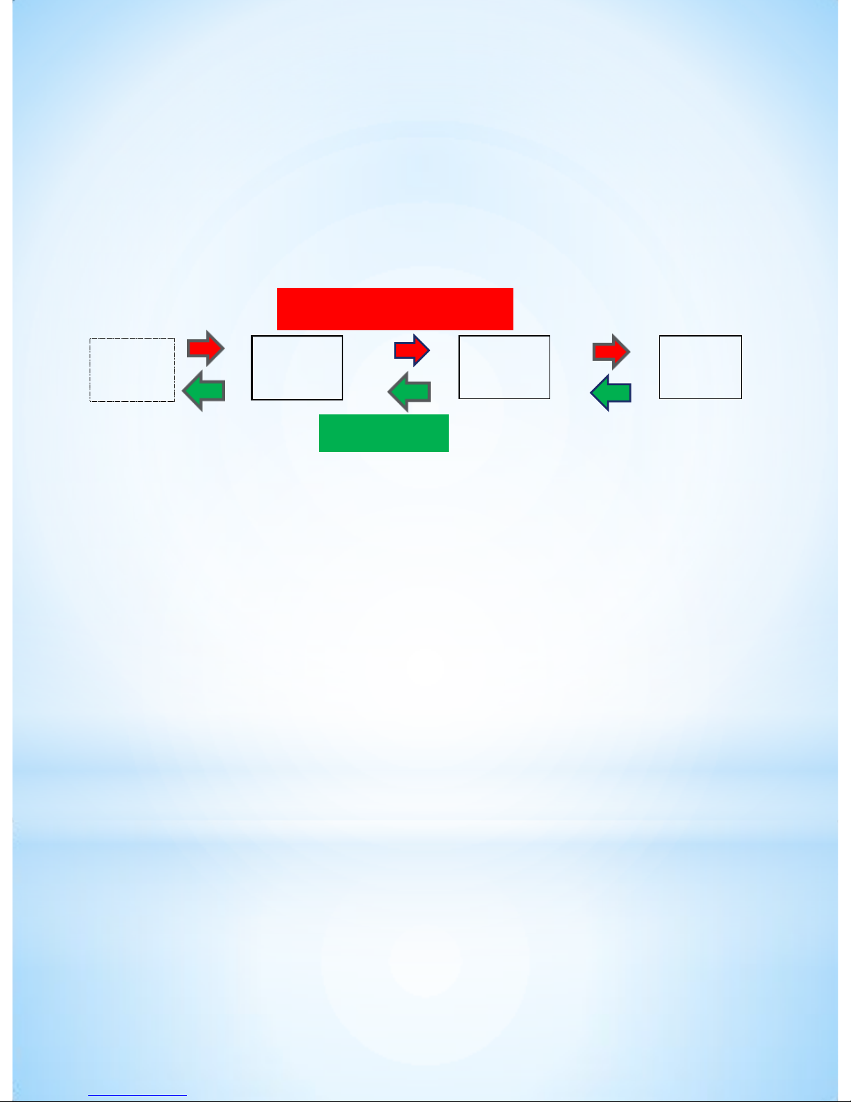
Upper
Board
Smart
Board
Lower
Board
Drive
Motor
Feed Back
Command Signal
The new TCS Series treads with the smart card system utilize a
digital signal for both command and feedback. This signal cannot be
tested with normal field equipment. Diagnostics must be done using the
status lights on both the lower control board and smart card.
2. DC DRIVE WITH SMART CARD INTERFACE (TES900, TLC900
and TPS850)
This system is basically the same as the above AC smart card
system; however, no motor transmit and receive LEDs are lit on
the DC smart card.
3. DC DRIVE (All TPS series except TPS850, Z5 series)
This system is the same as all our traditional DC drive systems
SYMPTOM GUIDE
A. DRIVE SYSTEM OVERVIEW
In this summary we are going to cover basic troubleshooting
techniques used in the industry to diagnose and repair True Fitness
treadmills more quickly and efficiently. Current True treadmills use 3
types of drive system:
1. AC DRIVE WITH SMART CARD INTERFACE (TCS Series and
TLC1100).
9
Tread Service Manual - July 2011
Proprietary & Confidential
TRUE Fitness Technology, Inc.
Proprietary & Confidential
TRUE Fitness Technology, Inc.
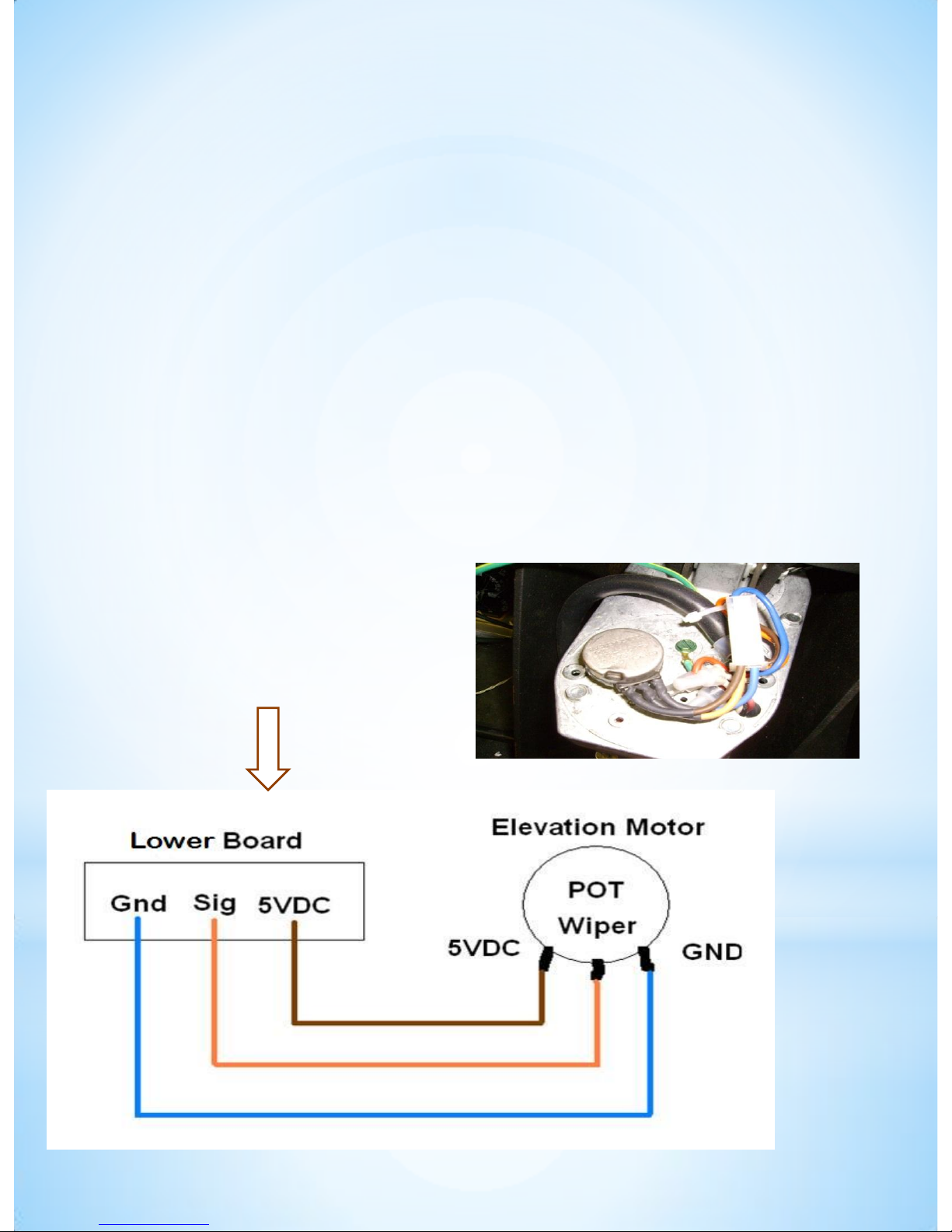
ELEVATION SYSTEM OVERVIEW
The elevation systems on all True Treadmills use AC
(Alternating Current) motors to lift the treadmill to the
desired elevation. This system uses a command from the
upper control board that is sent to the lower board which in
turn sends an AC voltage to the windings of the elevation
motor. There are two sets of windings on the AC incline
motor, one for each direction of motor movement. The
elevation motor has a potentiometer that sends a
feedback voltage back to the upper control board. This
voltage is converted into a digital signal and is displayed
on the upper board during Calibration Mode (see pg 47).
10
o Note: On units with Smart
Board -> 5 volts originates at
Smart Board. All other units,
-> 5V originates at upper board
Tread Service Manual - July 2011

Proprietary & Confidential
TRUE Fitness Technology, Inc.
Proprietary & Confidential
TRUE Fitness Technology, Inc.
ELEVATION SYSTEM OVERVIEW
(CONT.)
How this feedback is displayed varies with different models
and different consoles:
11
Note: See TRUE Dealer Portal for older model elevation values
Treadmill Series
Digital Value
Notes
CS 500, 550, 800 &
ES900 with
Touchscreen
With decline foot
14000 - 16000
At zero incline the incline digital value
displayed in calibration mode reads approx.
14000
- 16000. The DC voltage across the
orange and blue wires of the potentiometer
should read approx. 4.47 . As the treadmill
inclines, the displayed value increases while
the VDC decreases.
CS 500, 550, 800 &
ES900 with
Touchscreen
No decline foot
6500 - 8500
At zero incline the incline digital value
displayed in calibration mode reads approx.
6500
-7500. The DC voltage across the
orange and blue wires of the potentiometer
should read approx. 4.47 . As the treadmill
inclines, the displayed value increases while
the VDC decreases.
CS 550/800 & PS
series with 11"
console
28
At zero incline the incline digital value
displayed in calibration mode reads approx.
28. The DC voltage across the black and
white wires(TPS series) or (orange and blue
on TCS series) of the potentiometer should
read approx. 4.47 VDC . As the treadmill
inclines, the displayed value increases while
the VDC decreases
CS 500,LC series,
PS series with
2
Window
228
At zero incline the incline digital value
displayed in calibration mode reads approx.
228. The DC voltage across the orange and
blue wires of the potentiometer should read
approx. 4.47 VDC. As the treadmill inclines,
the displayed value decreases while the VDC
decreases.
Tread Service Manual - July 2011
Proprietary & Confidential
TRUE Fitness Technology, Inc.
Proprietary & Confidential
TRUE Fitness Technology, Inc.
D. TCS800 w/ touchscreen console:
At zero incline the incline digital value displayed in
calibration mode reads approx. 14000-16000. The DC
voltage across the orange and blue wires of the
potentiometer should read approx. 4.47 . As the
treadmill inclines the displayed value increases while
the VDC decreases.
ELEVATION OVERVIEW
(cont.)
Tread Service Manual - July 2011
12

Proprietary & Confidential
TRUE Fitness Technology, Inc.
Proprietary & Confidential
TRUE Fitness Technology, Inc.
B: ERROR CODES
13
GENERIC ERROR CODES
Error
Reason
Resolution
E1 RANGE
Elevation feedback values are
out of the minimum or
maximum range.
Pg. 15
-16
E1 STALL
Elevation feedback value does
not change when elevation
motor is commanded.
Pg. 15
-16
E2 CAL
Speed feedback is too far out of
the calibrated range.
Pg.
17
E2: OVERSPEED
Belt speed ramping too fast.
Can be caused by same issues
as E2 CAL
Pg.
17
E2: RECAL/ E3
EPROM
Computing error of upper board
processor.
Call Tech Support for
further troubleshooting.
E4: STUCK KEY
Control button continuously
activated.
Replace overlay.
On
machines with center pod
overlay, disconnect center
pod overlay cable to
determine which overlay is
defective. On TPS series
treads, surface mounted
switches activate control.
Remove switch board from
front plastic to determine if
functioning properly
E5: SENSOR
(aka NO SPEED
PULSE):
Upper control board detecting
any or below acceptable speed.
Pg.
17-22
Tread Service Manual - July 2011

Proprietary & Confidential
TRUE Fitness Technology, Inc.
Proprietary & Confidential
TRUE Fitness Technology, Inc.
ERROR CODES ASSOCIATED WITH NEW
SMART CARD
WRONG CONFIG: Smart card not compatible with configuration.
Check configuration of upper console.
SMART CARD COM: Lost communication between smart card
and upper control board. Check main data cables for continuity and
proper connections. Check status LEDS on smart card.
MOTOR MISMATCH: Motor type (AC vs DC) doesn’t match
smart card type (AC vs DC).
INCLINE REV ERROR: Elevation direction is reversed. Most likely
cause is incorrectly installed separate potentiometer cable on TPS style
incline systems. .
INCLINE OPEN: Elevation motor is disconnected. Check all
elevation connections. Check continuity on elevation and data cables
RPM MISMATCH: Belts moving speed from RS232 cable does
not match RPM detected by smart card. Most likely caused by
improper model configuration
CONSOLES BD LOST: Console’s communication is lost. Check
continuity of data cable and connections.
MOTOR BD COMM (AC ONLY): The motor controller’s
communication is lost between controller and smart card. Check
connections and cable continuity between smart card and lower control
board. Make sure RS232 cable is orientated correctly.
14
Tread Service Manual - July 2011

Proprietary & Confidential
TRUE Fitness Technology, Inc.
Proprietary & Confidential
TRUE Fitness Technology, Inc.
The elevation up and down LED’s on the lower boards of all
True Fitness Treadmills are used for elevation
troubleshooting.
These LED’s illuminate when a command is received from
the upper control board to raise or lower the incline.
If there is no illumination of incline LEDs, check data cable
for continuity.
If there is illumination of a incline LED and no motor
movement listen to the motor.
If there is a humming noise coming from the motor and no
movement, replace the motor.
If the LED’s illuminate and there is no motor humming, check
the 3 amp slow blow fuse on the lower board for continuity.
This fuse protects the 18 volt system that controls the
elevation relays. If there is no continuity, replace the fuse.
If the fuse blows a second time replace the lower board.
Caution! Unplug unit before removing fuses!
E1 STALL
15
Tread Service Manual - July 2011

Proprietary & Confidential
TRUE Fitness Technology, Inc.
Proprietary & Confidential
TRUE Fitness Technology, Inc.
• If the value at zero or -3% incline is outside the
acceptable range (see pg. 11) of the correct digital value,
the machine will give an elevation error (either E1 Stall
or E1 Range depending on model).
• On units with an external limit switch, the digital value
can be adjusted by disconnecting the elevation motor
from the incline rack and manually turning the linear
shaft of the incline motor until it reads the correct digital
value at 0% or -3%.
• On treadmills with internal limit switches in the incline
motor the ideal zero will be set when the internal switch
activates.
• A value reading 255 or 0 often indicates over travel of
the potentiometer or a wire disconnect between the
potentiometer and the upper control panel.
E1 STALL/ E1 RANGE
16
Tread Service Manual - July 2011

Proprietary & Confidential
TRUE Fitness Technology, Inc.
Proprietary & Confidential
TRUE Fitness Technology, Inc.
This error will occur if the upper and the lower boards lose their
calibration parameters. See calibration procedure(pg 47)
Note: May be caused by speed fluctuation.
•Check for high friction by performing a Push-off test.(pg 35)
•To perform this test raise the elevation to the highest level and
remove safety key.
•While standing on the belt push away from the handle bar.
•If there is high friction between the belt and deck it will be difficult
to push away.
•Units with low friction will be easy to push away.
•High friction can lead to excess amp draw on the motor. The
motor may overcompensate causing an error code. If this is not
addressed, it will lead to motor controller failure.
•Replace running belt and deck as needed
•Check the line voltage for fluctuations. This can cause erratic
speeds.
E2 CAL
17
Tread Service Manual - July 2011

Proprietary & Confidential
TRUE Fitness Technology, Inc.
Proprietary & Confidential
TRUE Fitness Technology, Inc.
E5 Sensor Error (without belt movement):
If the upper control board does not see adequate feedback from the
speed sensor when the belt is being commanded to move this error
will occur.
This error can occur for different reasons which we have listed
below.
First, if there is a break in the main data cable, the speed feedback
information will not make it back to the upper board.
Check to see if there is speed feedback in the upper board while
in calibration.
Next check continuity on the data cable to verify there is no break
in the connection.
If the upper board command signal is not being received at the lower
board there will be no belt movement.
E5 SENSOR
18
Tread Service Manual - July 2011
 Loading...