

True Fitness ES900 Owner's Manual
* Assembly Guide & Warranty Card Included
ES900 TREADMILL
OWNER’S MANUAL
Revision 100214

ES900 TREADMILL OWNERS MANUAL
IMPORTANT:
All Products shown are prototype. Actual product delivered may vary.
Product specifications, features & software are subject to change without notice.
For the most up to date owner’s manual please visit www.truefitness.com.
For documents in additional languages please visit www.truefitness.com/document-library/29/international-manuals
IMPORTANTE:
Todos los productos mostrados son prototipos. La realidad el producto suministrado puede diferir.
Especificaciones de productos, características y software están sujetas a cambios sin previo aviso.
Para la más actualizada de este manual del propietario, por favor visite www.truefitness.com
Para los documentos en otros idiomas, por favor visite www.truefitness.com/document-library/29/international-manuals
IMPORTANT:
Tous les produits présentés sont prototype. Le produit réel livré peut varier.
Spécifications du produit, caractéristiques et logiciels sont sujettes à modification sans préavis.
Pour la plus à jour le manuel du propriétaire s'il vous plaît visitez www.truefitness.com.
Pour
documents dans des langues supplémentaires, veuillez www.truefitness.com/document-library/29/international-manuals de visite
重要提示:
显示所有产品的原型。实际交付的产品可能有所不同
产品规格,功能和软件如有更改,恕不另行通知
迄今为止对于大多数的使用说明书,请访问www.truefitness.com
对于其他语言的文档,请访问www.truefitness.com/document-library/29/international-manuals
:ﻡﺎﻫ
ﻊﻳﻣﺟ ﺕﺎﺟﺗﻧﻣﻟﺍ ﻲﻫ ﺔﺿﻭﺭﻌﻣﻟﺍ ﺝﺫﻭﻣﻧﻟﺍ .ﻑﻠﺗﺧﺗ ﺩﻗ ﻲﻠﻌﻔﻟﺍ ﺞﺗﻧﻣﻟﺍ .ﺎﻬﻣﻳﻠﺳﺗ
ﻭ ،ﺞﺗﻧﻣﻟﺍ ﺕﺎﻔﺻﺍﻭﻣ ﺞﻣﺍﺭﺑﻟﺍﻭ ﺕﺍﺯﻳﻣﻟﺍﺭﻳﻳﻐﺗﻠﻟ ﺔﻠﺑﺎﻗ ﺭﺎﻌﺷﺇ ﻥﻭﺩ.
ﻟ ﻝﺻﻳ ﺎﻣ ﻡﻅﻌﻣﻥﻵﺍ ﻰﺗﺣ ﻙﻟﺎﻣﻟﺍ ﻝﻳﻟﺩ ﺓﺭﺎﻳﺯ ﻰﺟﺭﻳ
www.truefitness.com.
ﺕﺍﺩﻧﺗﺳﻣﻠﻟ ﺕﺎﻐﻟ ﻲﻓ ﻰﺟﺭﻳ ،ﺔﻳﻓﺎﺿﺇ ﺓﺭﺎﻳﺯ
WICHTIG:
Alle hier gezeigten Produkte sind Prototypen. Das tatsächliche Produkt ausgeliefert wird, kann variieren.
Produkt-Spezifikationen, Funktionen und Software können sich ohne vorherige Ankündigung ändern.
In den meisten Fällen bis zu Bedienungsanleitung Bisher besuchen Sie bitte www.truefitness.com.
Für Dokumente in weiteren Sprachen finden Sie unter www.truefitness.com/document-library/29/international-manuals
BELANGRIJK:
Alle getoonde producten zijn prototype. Daadwerkelijke product geleverd kan verschillen.
Product specificaties, eigenschappen & software zijn onderhevig aan verandering zonder kennisgeving.
Voor de meest actuele handleiding van de eigenaar kunt u terecht www.truefitness.com.
Voor documenten in andere talen kunt u terecht op www.truefitness.com/document-library/29/international-manuals
ВАЖНО:
Все товары указаны прототипа. Фактический продукт, поставляемый могут отличаться.
Технические характеристики, особенности и программного обеспечения могут быть изменены без предварительного
уведомления.
Для получения самой последней на сегодняшний день руководство по эксплуатации пожалуйста, посетите
www.truefitness.com
.Для документов на другие языки, пожалуйста, посетите www.truefitness.com/document-library/29/international-manuals
www.truefitness.com/document-library/29/international-manuals
Truefitness.com / 800.426.6570 / 636.272.7100

ES900 TREADMILL OWNERS MANUAL
Frank Trulaske, founder and CEO of TRUE, has had the same simple philosophy of delivering superior products, service
and support for over 30 years. Today, TRUE is the global leader in premium cardio equipment for the commercial and
residential markets. Our goal is to be the leader in technology, innovation, performance, safety and style. TRUE has
received many awards for its commercial and retail product over the years and remains the benchmark for the industry.
Fitness facilities and consumers invest in TRUE products for their durable commercial platforms used in all its cardio
products, both commercial and residential alike.
The proud manufacturing tradition of quality and the culture of innovation at TRUE have given rise to a full line of
truly extraordinary treadmills, indoor cycles and elliptical cross-trainers. As a result, people all over the world are
benefiting from the TRUE experience. Innovation across the full product line has made TRUE successful and is a
trademark of the TRUE heritage. TRUE’s patented Heart Rate Control® technology is just one of the remarkable ways we
deliver simple and superior performance every user can enjoy, and most importantly, use to achieve personal health and
fitness goals.
TRUE strives to perfect biomechanically correct and orthopedically comfortable, functional products. Whether it be the
mesh seat in the recumbent bike, the Soft Step® in the elliptical cross-trainers or the Soft System® in our treadmills, we
deliver the best.
At the heart of our success is the relentless and systematic life testing of both our products and their components. We
have dedicated employees who understand our philosophy is to deliver the best products in the world.
Our goal is not to sell the most cardio products in the world, but to deliver the world’s best premium equipment for our
customers’ health and fitness solutions.
To own a TRUE machine is to be part of an exclusive fitness community that delivers results – your results.
Thank you for becoming a part of the TRUE experience.
TRANSCEND ALL OTHERS!
Truefitness.com / 800.426.6570 / 636.272.7100

ES900 TREADMILL OWNERS MANUAL
Chapter 1: Safety Instructions
Chapter 4B: Escalate15 Operation
TABLE OF CONTENTS
Safety Instructions 1
Use of Safety Key 4
Space Requirements 4
Grounding Instructions 5
Power Requirements 6
Warning Decals 7
Compliances 7
Chapter 2: Assembly Instructions
Pre-Assembly Checklist 9
Assembly Steps 11
Chapter 3: Product Overview
Treadmill Overview 33
Chapter 4: Programming & Operation
Heart Rate Monitoring 35
Heart Rate Control 36
Program Descriptions 37
Virtual Active ®Videos 41
Chapter 4A: Transcend Operation
Transcend Overview 43
Touchscreen Introduction 45
Touchscreen Navigation 45
Web Browser 51
iPod® Integration 52
Bluetooth Audio 53
TV Controls 55
Virtual Active® 56
Netpulse® 56
Advanced Console Functions 57
:
Escalate15 Overview 75
Console Navigation 77
TV Controls 81
iPod® Integration 82
Bluetooth Audio 83
Advanced Console Functions 85
Chapter 4B: Escalate9 Operation
Escalate 9 Overview 102
Console Navigation 104
Advanced Console Functions 110
Chapter 5: Care & Maintenance
Care & Maintenance 118
Cleaning the Equipment 118
Running Belt Alignment 119
Tensioning the Running Belt 120
Treadmill Lubrication 120
Leveling the Treadmill 121
Other Scheduled Preventive Maintenance 121
Long Term Storage 121
Chapter 6: Customer Service
Contacting Service 122
Contacting Sales 122
Reporting Freight Claims or Parts Damage 123
Chapter 7: Additional Information
Troubleshooting Guide 124
Product Specifications 130
Warranty Information 132
Truefitness.com / 800.426.6570 / 636.272.7100

CHAPTER 1: SAFETY INSTRUCTIONS
IMPORTANT SAFETY INSTRUCTIONS
SAVE THESE SAFETY INSTRUCTIONS
This treadmill is intended for in-home use only; do not use this treadmill in a commercial or institutional setting.
Doing so may void the expressed warranty.
WARNING: All EXERCISERS MUST READ ALL INSTRUCTIONS BEFORE USING THE TREADMILL.
WARNING: Heart rate monitoring systems may be inaccurate for some individuals. Over-exercising may result in
serious injury or death. If you feel faint, stop exercising immediately.
WARNING: Equipment should be immediately taken out of use if it fails to work properly or when a warning is
presented electronically.
TRUE STRONGLY recommends seeing a physician for a complete medical exam before undertaking an exercise program,
particularly if the user has a family history of high blood pressure or heart disease, is over the age of 45, smokes, has high
cholesterol, is obese or has not exercised regularly in the past year. Additionally, TRUE recommends consulting a fitness
professional on the correct use of this product. If at any time while exercising the user experiences faintness, dizziness,
pain or shortness of breath, he or she must stop immediately.
WARNING: To reduce the risk of electrical shock, always unplug this TRUE product before cleaning or
attempting any maintenance activity. Do not handle the plug with wet hands.
WARNING: To reduce the risk of burns, fire, electric shock or injury, it is imperative to connect each product to a
properly grounded 110V electrical outlet. A risk of electrical shock may result from improper connection of the
equipment’s grounding conductor. Check with a qualified electrician if you are unsure about proper grounding
techniques. Do not modify the plug provided with this product. If it will not fit an electrical outlet, have a proper
outlet installed by a qualified electrician. Your TRUE Fitness product must be properly grounded to reduce risk of
shock if the treadmill malfunctions. Your treadmill is equipped with an electrical cord, which includes an
equipment grounding conductor and a grounding plug. The plug must be inserted into an outlet that has been
properly installed and grounded in accordance with all local codes and ordinances. A temporary adapter cannot
be used to connect this plug to a two-pole receptacle in North America. If a properly grounded 15 amp outlet is
not available, a qualified electrician must install one.
WARNING: Do not move the equipment by lifting the console. Do not use the console as a handlebar during a workout.
WARNING: This product contains chemicals known to the state of California to cause cancer and birth defects or other
reproductive harm.
WARNING: Keep equipment stable on flat ground.
WARNING: Replace warning labels that may be worn, damaged or missing
WARNING: Replace any non-working or damaged components; remove the unit from service until repair is
performed.
Truefitness.com / 800.426.6570 / 636.272.7100 1

CHAPTER 1: SAFETY INSTRUCTIONS
WARNING: To reduce the risk of burns, fire and electric shock or injury to persons, follow these instructions:
• This appliance should never be left unattended when plugged in.
• Do not use any type of extension cord with this product.
• Unplug it from the outlet when not in use and before any servicing.
• Do not operate the equipment while being covered with a blanket, plastic, or anything that insulates or stops
airflow.
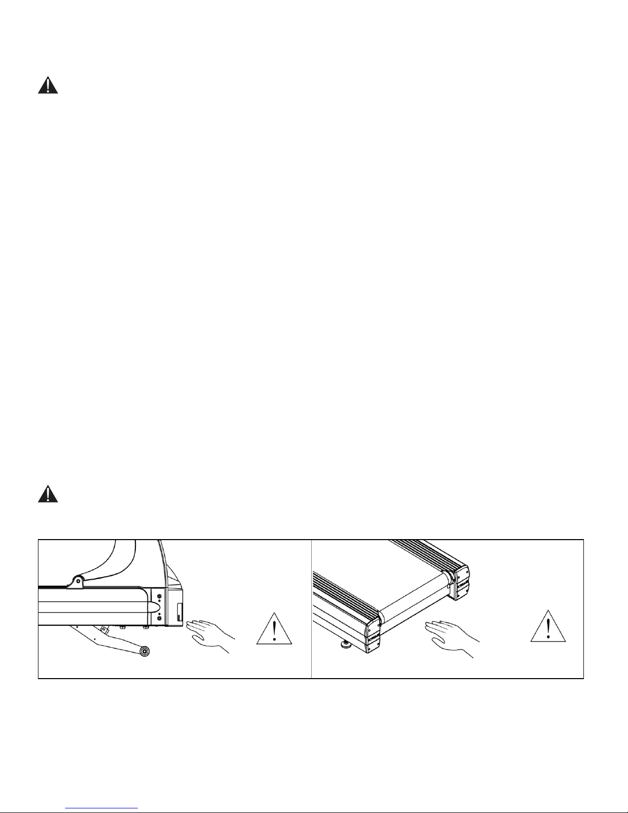
WARNING: Risk of personal injury-crushing hazard when treadmill is in operation - Keep feet, hands, and
fingers away from moving parts.
CAUTION:
• Health related injuries may result from incorrect or excessive use of exercise equipment.
• Do not use typing or web surfing features at excessive speeds. Always stabilize yourself by holding a stationary
handle when using typing or web surfing features. (Varies by console option)
• Do not use the contact heart rate grips as a handlebar during a workout.
• Any changes or modifications to this equipment could void the product warranty.
• To disconnect, turn power OFF at the ON/OFF switch if applicable, then remove plug from electrical outlet.
• Never operate a TRUE product if it has a damaged power cord or electrical plug, or if it has been dropped,
damaged, or even partially immersed in water. Contact TRUE Customer Service for a replacement.
• Use a TRUE AC power cord or AC/DC adapter only.
*Note the plug configuration for the power adapter may vary by country.
• Position this product so the power cord plug is accessible to the user.
• Keep the power cord away from heated surfaces. Do not pull the equipment by the power cord or use the cord as a
handle. Do not run the power cord along the side or under the treadmill.
• If the electrical supply cord is damaged it must be replaced by the manufacturer, an authorized service agent, or a
similarly qualified person to avoid a hazard.
• Do not use this product in areas where aerosol spray products are being used or where oxygen is being
administered. Such substances create the danger of combustion and explosion.
• Always follow the console instructions for proper operation.
• Close supervision is necessary when used near children under the age of 15, or disabled persons.
• Do not use this product outdoors, near water, while wet, or in areas of high humidity including extreme
temperature changes
• Never operate a TRUE product with the air openings blocked. Keep air openings free of lint, hair or any
obstructing material.
• Never insert objects into any openings in this product. If an object should drop inside, turn off the power, unplug
the power cord from the outlet and carefully retrieve it. If the item cannot be reached, contact TRUE Customer
Service.
• Never place liquids of any type directly on the unit except in the accessory tray or bottle holders. Containers with
lids are recommended.
• Wear shoes with rubber or high traction soles. Do not use shoes with heels, leather soles, cleats or spikes. Make
sure no stones are embedded in the soles. Do not use this product in bare feet. Keep all loose clothing, shoelaces
and towels away from moving parts.
• Do not reach into or underneath the unit, or tip it on its side during operation.
Truefitness.com / 800.426.6570 / 636.272.7100 2
CHAPTER 1: SAFETY INSTRUCTIONS
CAUTION (continued):
• Use correct ergonomic positioning while running on treadmill.
• Do not allow animals on or near the equipment while in operation.
• Use the side handrails whenever additional stability is required. In case of emergency, such as tripping, the side
handrails should be grabbed and the user should place his/her feet on the side platforms. The front handlebars
should be used to grasp the heart rate sensors or to rest the hand on while operating the activity zone keys, but not
for stability, emergency, or continuous use.
• Do not exceed maximum user weight of 400 lbs (181 kg).
• Do not use if you have a cold or fever.
• When using this exercise machine, basic precautions should always be followed.
• Use this equipment only for its intended use as described in this manual.
• Do not use attachments not recommended by the manufacturer.
• Allow only trained personnel to service this equipment.
• Avoid the possibility of bystanders being struck or caught between moving parts by making sure that they are out
of reach of the equipment while it is in motion.
• This appliance can be used by children aged from 8 years and above and persons with reduced physical, sensory or
mental capabilities or lack of experience and knowledge if they have been given supervision or instruction
concerning use of the appliance in a safe way and understand the hazards involved.
• Children shall not play with the appliance.
• Cleaning and user maintenance shall not be made by children without supervision.
• Allow only one person at a time on the equipment while it’s operating.
• It is the sole responsibility of the owner/operator to ensure regular and scheduled maintenance is performed.
• To avoid injury stand on the side rails before starting the treadmill.
• Avoid exiting treadmill while leaving the tread belt in motion.
• Never walk or jog backwards on the treadmill.
CAUTION:
• To avoid serious injury, do not touch the incline rack while the treadmill is in use.
• To avoid serious injury, do not touch the belt while the treadmill is in use.
Truefitness.com / 800.426.6570 / 636.272.7100 3
CHAPTER 1: SAFETY INSTRUCTIONS
3 2 1
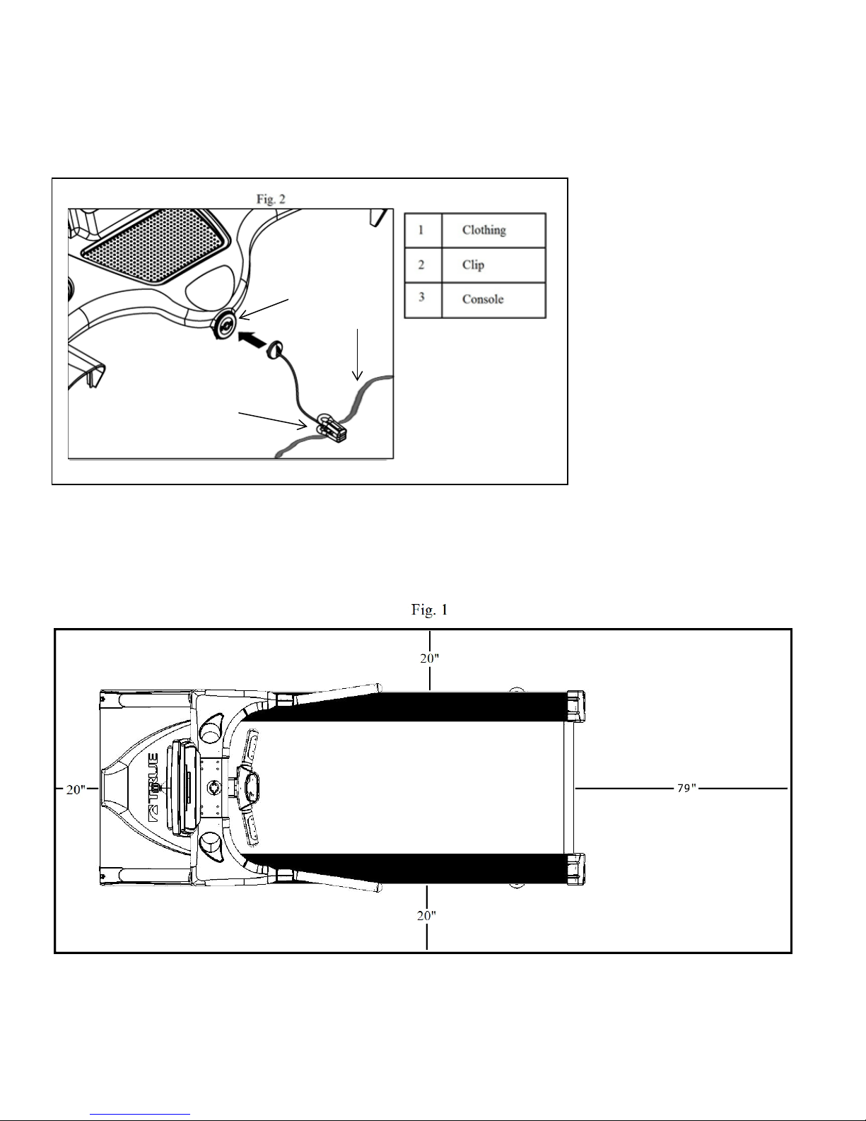
USE OF SAFETY KEY (E-STOP):
• Attach the safety clip to your clothing before each workout and when treadmill is in use. (See Fig 2)
• Attach the magnetic key to the treadmill console assembly
SPACE REQUIREMENTS:
SPACE REQUIREMENTS:
TRUE’s recommendation is to leave a minimum of 20” (0.5m) on each side of the treadmill and a 79” (2 m) safety zone at
the rear of the treadmill. (See Fig 1)
Truefitness.com / 800.426.6570 / 636.272.7100 4
CHAPTER 1: SAFETY INSTRUCTIONS
GROUNDING INSTRUCTIONS:
This product must be grounded, if it should malfunction or breakdown, grounding provides a path of least resistance for
electric current to reduce the risk of electric shock. This product is equipped with a cord having an equipment-grounding
conductor and a grounding plug. The plug must be plugged into an appropriate outlet that is properly installed and
grounded in accordance with all local codes and ordinances.
DANGER
• Improper connection of the equipment-grounding conductor can result in a risk of electric shock.
• Check with a qualified electrician or serviceman if you are in doubt as to whether the product is properly
grounded. Do not modify the plug provided with the product. If it will not fit the outlet, have a proper outlet
installed by a qualified electrician.
• Do not remove the motor cover or you may risk injury due to electric shock.
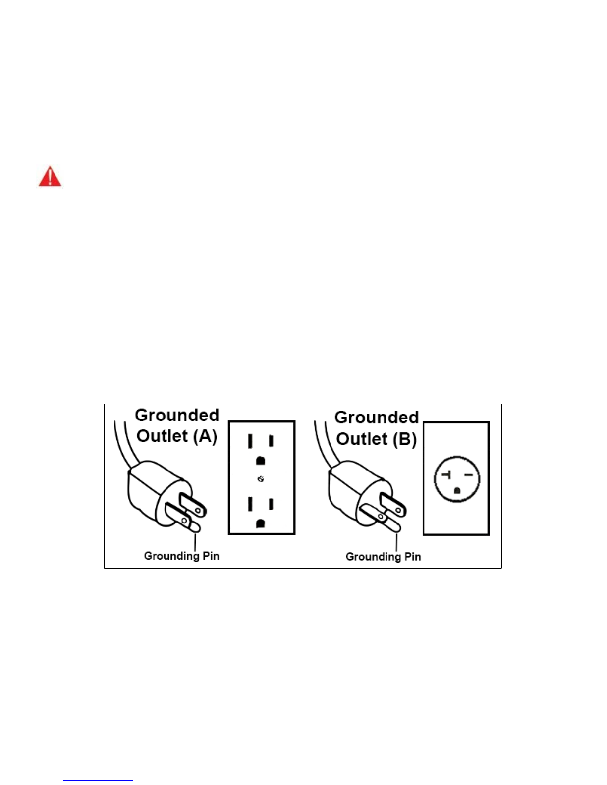
• The 120-V model is for use on a nominal 120-V circuit and has a grounding plug that looks like the plug
illustrated in figure A. Make sure the product is connected to an outlet having the same configuration as the plug.
No adaptor should be used with this product.
• The 230-V model is for use on a circuit having a nominal rating more than 120-V and is factory-equipped with a
specific electric cord and has a grounding plug that looks like the plug illustrated in figure B. Make sure that the
product is connected to an outlet having the same configuration as the plug in Figure B. No adapter should be
used with this product. If the product must be reconnected for use on a different type of electric circuit, the
reconnection should be made by qualified service personnel.
:
Truefitness.com / 800.426.6570 / 636.272.7100 5
CHAPTER 1: SAFETY INSTRUCTIONS
Truefitness.com / 800.426.6570 / 636.272.7100 6
CHAPTER 1: SAFETY INSTRUCTIONS
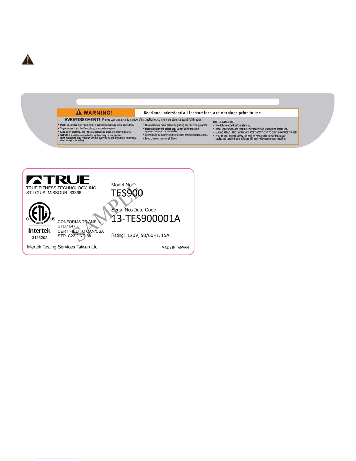
WARNING DECALS:
WARNING: Replace warning labels that may be worn, damaged or missing
To replace any worn or missing warning decals contact TRUE FITNESS by visiting www.truefitness.com or contact
customer service at 800-883-8783.
COMPLIANCES:
This equipment complies with all applicable codes and regulations. For a complete list of compliances, please visit
www.truefitness.com
Truefitness.com / 800.426.6570 / 636.272.7100 7

CHAPTER 2: ASSEMBLY INSTRUCTIONS
• Read and understand all instructions and warnings prior to use.
IMPORTANT SAFETY INSTRUCTIONS
• Obtain a medical exam before beginning any exercise program. If at any time during exercise you
feel faint, dizzy, or experience pain, stop and consult your physician.
• Obtain proper instruction prior to use.
• This treadmill is intended for in-home use only.
• Inspect the treadmill for incorrect, worn, or loose components and do not use until corrected,
replaced, or tightened prior to use.
• Do not wear loose or dangling clothing while using the treadmill.
• Care should be used when mounting or dismounting the treadmill.
• Read, understand, and test the emergency stop procedures before use.
• Disconnect all power before servicing the treadmill.
• Do not exceed maximum user weight of 400 lbs.
• Keep the top side of the moving surface clean and dry.
• Keep children and animals away.
• Use caution when moving and assembling treadmill.
• All exercise equipment is potentially hazardous. If attention is not paid to the conditions of
equipment usage, death, or serious injury could occur.
• Save these instructions.
Basic Guidelines for Setting Up Your Treadmill:
After removing the treadmill from the packaging, place your treadmill on a clean, level surface. Make sure the electrical
cord easily reaches a grounded three-pronged outlet and has enough slack to allow the deck to incline without tightening
the cord. Do not allow the treadmill assembly to rest on the cord.
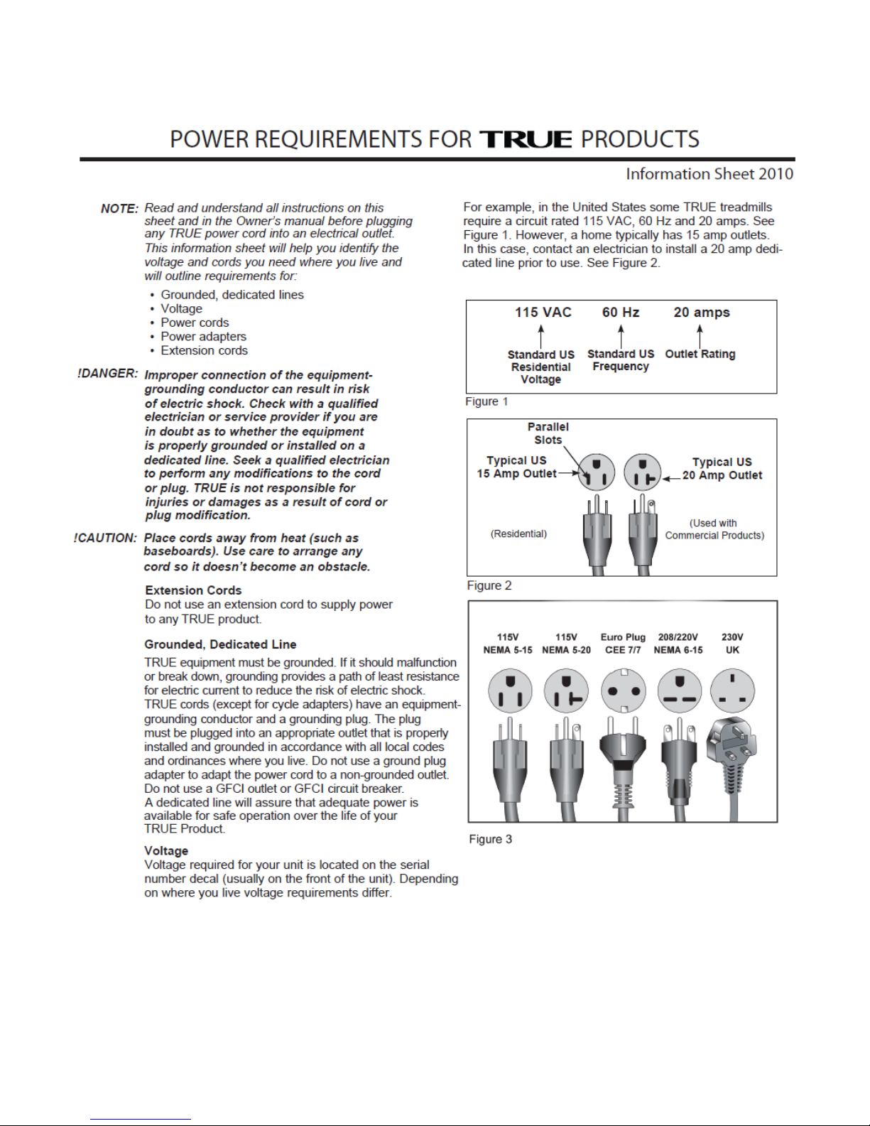
Important Electrical Requirements – 120V:
You r TR U E treadmill requires a dedicated 120 volt, alternating current (AC), 20 amp grounded outlet circuit. This means
nothing else can be plugged into the same circuit. Most power circuits are rated for this 120V AC 20 amp requirement, but
you must ensure the treadmill does not share the circuit with anything else.
Danger: Do not use an extension cord or ungrounded outlet:
The ground helps prevent electrical damage to your treadmill and enhances your safety by helping to prevent shock. Check
with a qualified electrician or serviceman if you are in doubt as to whether the treadmill is properly grounded. Do not
modify the plug provided with the treadmill if it will not fit the outlet. Have a proper outlet installed by a qualified
electrician.
Truefitness.com / 800.426.6570 / 636.272.7100 8
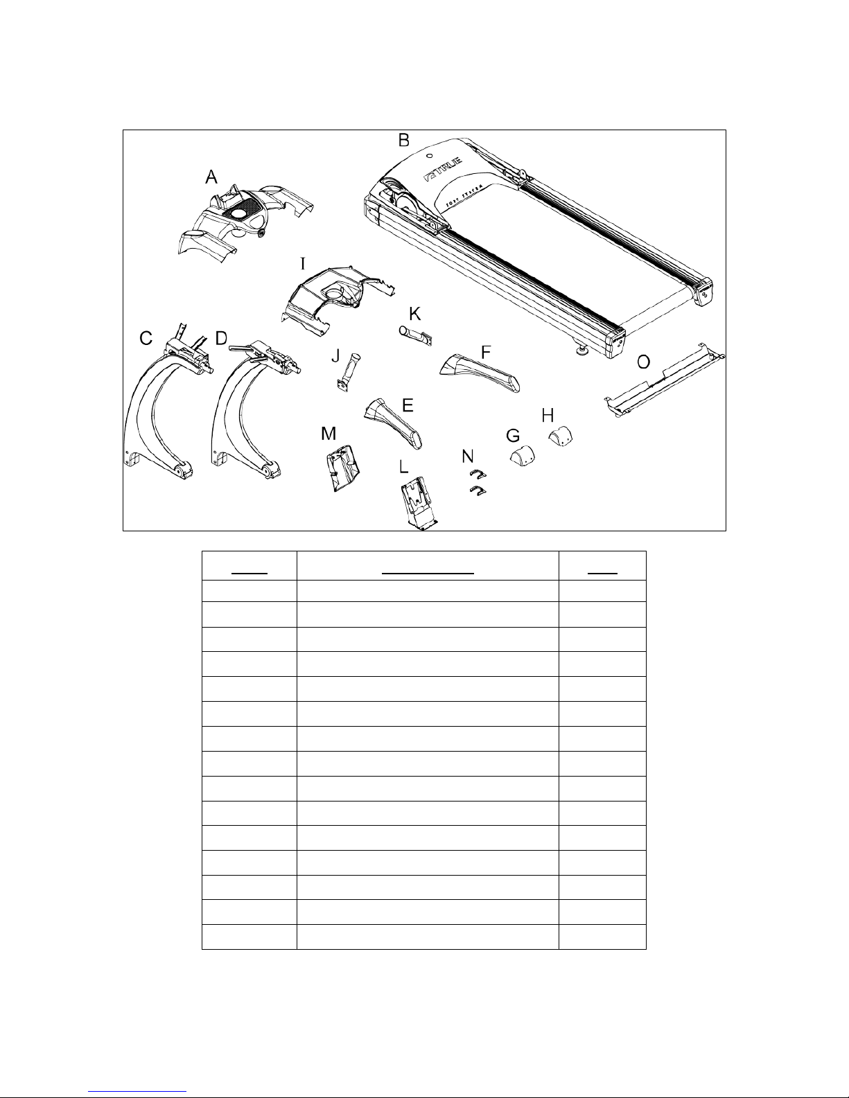
CHAPTER 2: ASSEMBLY INSTRUCTIONS
Item
Description
Qty
C
Pedestal - Left
1
PRE-ASSEMBLY CHECK LIST:
A Console Rack 1
B Frame 1
D Pedestal - Right 1
E Handrail - Left 1
F Handrail - Right 1
G Pivot Trim Cover - Left 1
H Pivot Trim Cover - Right 1
I Lower Console Rack Cover 1
J Hand Grip Assembly - Left 1
K Hand Grip Assembly - Right 1
L Console Mast 1
M Rear Console Cover 1
N Hand Grip Base Cover 2
O Decline Foot 1
Truefitness.com / 800.426.6570 / 636.272.7100 9
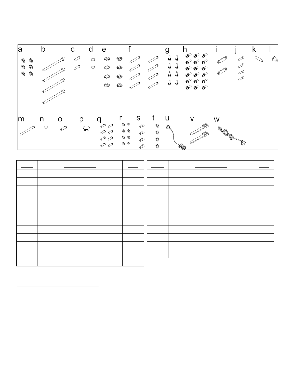
CHAPTER 2: ASSEMBLY INSTRUCTIONS
Item
Description
Qty
Item
Description
Qty
g
Screw 1/4˝-20x20mm
8 s
Bolt 5/16˝-24x16mm
4
h
Round Philips screwM4xP0.7x12
18 t
Spring washer M8
4
i
Pivot Trim Cover Plate
2 u
Safety Key
1
k
Spacer
1 w
Power cord
1
l
Power Cord Retainer
1
• 15/16, 7/8, 7/16 and 1/2 inch Open End Wrenches
• 7/16 inch socket with extension and ratchet
PRE-ASSEMBLY CHECK LIST (continued):
a Spring washer3/8˝ 6 m Round Philips screwM5xP0.8x60 1
b Bolt 3/8˝-16x140mm 4 n WasherØ6xØ19x1.5t 1
c Bolt 3/8˝-16x20mm 2 o Screw M5xP0.8x20 1
d O ring 2 p Motor Cover Plug 1
e Outer tooth washer M8 8 q Screw 1/4˝-20UNFx16mm 8
f Truss hex screw 5/16˝-24x38mm 8 r Spring washer1/4˝ 8
j Screw #10-32x15mm 4 v Wire Ties 2
Tools Required (not included):
• Long Nose Pliers
• 3/16 and 7/32 inch hex keys
• #2 Phillips Screwdriver
Truefitness.com / 800.426.6570 / 636.272.7100 10
CHAPTER 2: ASSEMBLY INSTRUCTIONS
TREADMILL ASSEMBLY STEPS:
CAUTION:
• Use caution when assembling treadmill. Unpacking and assembling of this treadmill is a two person task.
• Remove all treadmill components from packaging.
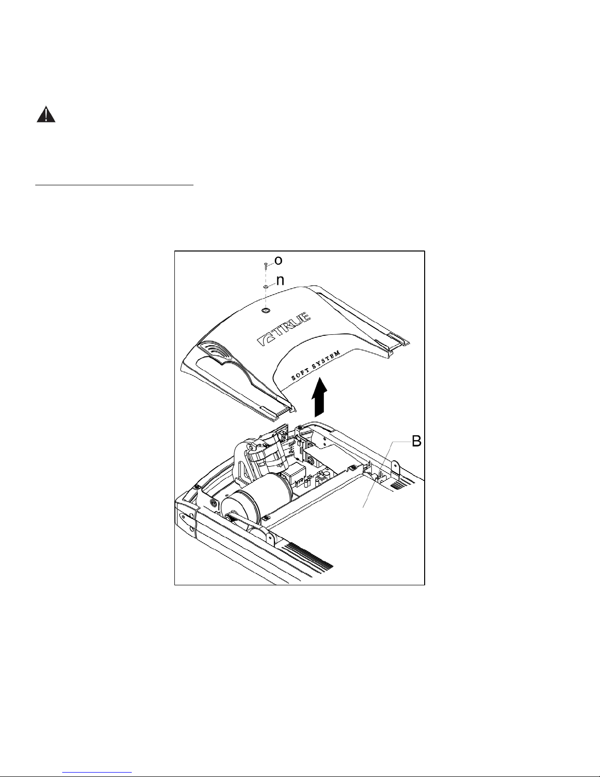
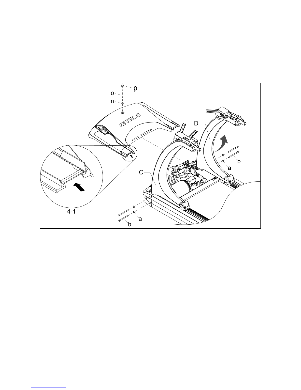
Step 1 Remove Motor Cover:
a) Remove the screw (o) and washer (n) from the motor cover and set to the side.
b) Remove the motor cover from the treadmill frame (B)
Fig. 1
Truefitness.com / 800.426.6570 / 636.272.7100 11
CHAPTER 2: ASSEMBLY INSTRUCTIONS
TREADMILL ASSEMBLY STEPS (continued):
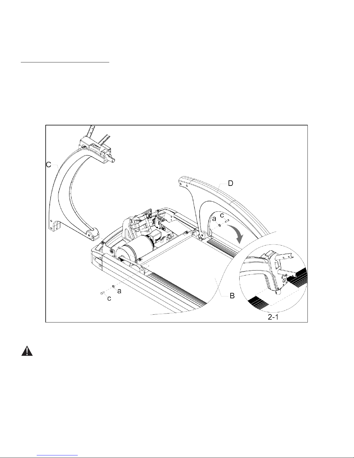
Step 2 Pedestal Installation:
a) Place a section of cardboard onto right straddle cover as shown in Fig 2-1. Remove twist tie from cable bundle.
b) Install Pedestal – R (D) into Frame (B) rotated down as shown in Fig. 2. This position will help prevent cable
damage.
c) Using 7/32 inch hex key, install Bolt 3/8-16 UNC x 3/4 (c) and Washer 3/8 – Split (a) into pivot of Pedestal – R but
do not tighten yet.
d) Insert Pedestal – L (C) into Frame as shown in Fig. 2 with bolt (c) and washer (a) but do not tighten yet.
CAUTION:
Pedestals can pivot until secured in front. Do not grab top of pedestal.
Truefitness.com / 800.426.6570 / 636.272.7100 12
Fig. 2
CHAPTER 2: ASSEMBLY INSTRUCTIONS
Transcend
16”Touchscreen
Transcend
10”Touchscreen
Escalate
15” TFT
Escalate
9”TFT
Step 3-2A
Step 3-2A
Step 3-2A
Step 3-2B
TREADMILL ASSEMBLY STEPS (continued):
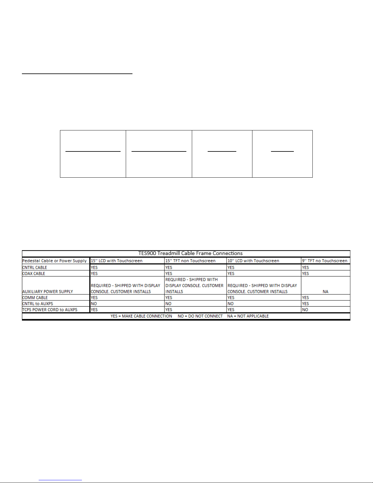
Important Display Specification:
Verify on customer product order what type of display will be installed on this treadmill.
Listed below are the four display options for this series of treadmill.
Find the correct Display Option for assembly and follow frame cable routing (step 3) directions for either section 3-2A or
3-2B and for console cable connections (step 12) follow section 12A or 12B
Step 12A
NOTE: Cables will be labeled near their connector with identifying names such as those listed in BOLD TEXT throughout
these instructions. Also listed in these instructions are the cable part numbers (KDCA-“xx”), which are called out in each
step.
NOTE: See TES900 Treadmill Frame Cable Connection Table below for the cable connections summary.
NOTE: Reference Wiring Schematic and Frame Cable Routing Diagram contained in these assembly instructions. Yo u
may remove from packet to aid in assembly but if you remove we recommend you retain these diagrams with the
instructions for future reference.
Step 12A
Step 12A
Step 12B
Truefitness.com / 800.426.6570 / 636.272.7100 13
CHAPTER 2: ASSEMBLY INSTRUCTIONS
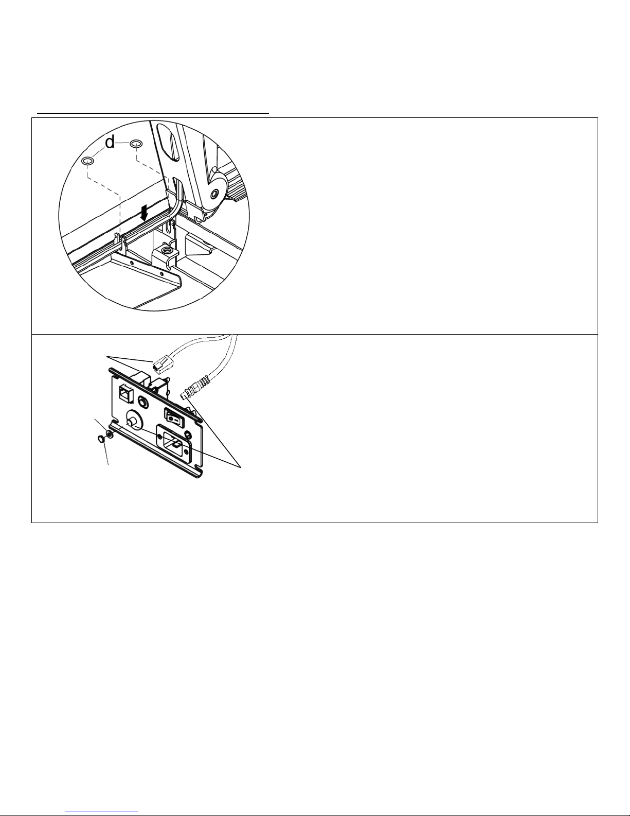
a) Route the cables exiting from Pedestal – R into cable restraints
Fig 3-1-2
b) Route the COAX Cable and Network Cable to the front of
Fig 3-1-1
Washer
Nut
Connect Network
Cable Here
Pass COAX Cable
Through Here
TREADMILL ASSEMBLY STEPS (continued):
Step 3-1 Frame Cable Connections:
and secure with two O-rings (d) as shown in Fig. 3-1-1 to the
left. Eliminate any slack in cables to ensure they are not
pinched when pedestals are upright.
c) Connect the network cable to the network jack on the power
d) Remove nut and washer from front of COAX Cable as
e) Pass front of COAX Cable through hole in electrical panel
the treadmill frame.
plate as shown in Fig 3-1-2
shown in figure 3-1-2
and install washer and tighten nut using 1/2 inch open end
wrench on nut and long nose pliers on connector portion of
cable.
NOTE: Torque specification for tightening all COAX
connections is 1.8 ft-lb
Truefitness.com / 800.426.6570 / 636.272.7100 14
CHAPTER 2: ASSEMBLY INSTRUCTIONS
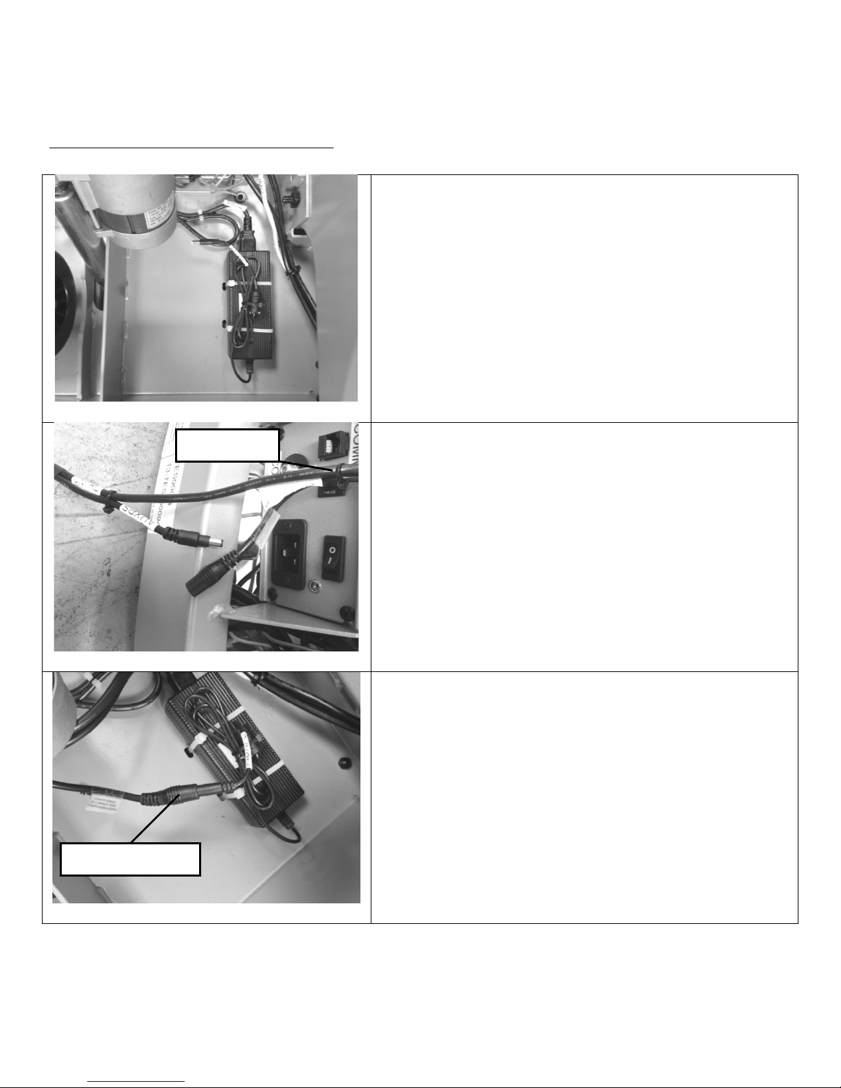
Picture 3-2A-1
a) Place Auxiliary Power Supply (included in console box), in
Picture 3-2A-2
d) Separate the AUXPS cables that are attached to the CTRL
Picture 3-2A-3
e) Connect the female end of the AUXPS Cable coming from
Connection Made
Cut Wire Tie
TREADMILL ASSEMBLY STEPS (continued):
Step 3-2A Frame Cable Connections:
*TOUCHSCREEN CONSOLES & 15” TFT CONSOLES ONLY
motor area floor location shown in picture 3-2A-1
b) Connect TCPS Power Supply AC connector (large
connector w/ 3 pins) into Auxiliary Power Supply as shown
in picture. Make sure connector is fully inserted.
c) Secure Auxiliary Power Supply to floor using the supplied
wire ties.
cable and cut the wire tie holding the female end of the
AUXPS cable to the CTRL cable as shown in picture 3-2A-2
Pedestal to AUXPS Power Supply Cable. See picture 3-2A-3
NOTE: The male end of the AUXPS cable wire tied to the
CNTRL cable is not used for this installation.
Truefitness.com / 800.426.6570 / 636.272.7100 15
CHAPTER 2: ASSEMBLY INSTRUCTIONS
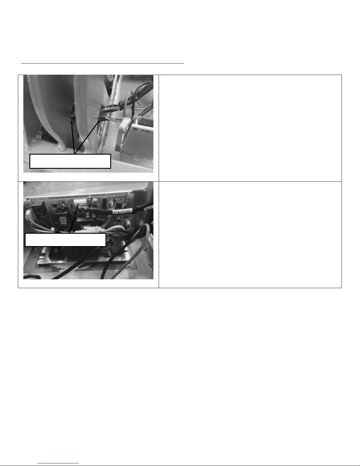
TREADMILL ASSEMBLY STEPS (continued):
*TOUCHSCREEN CONSOLES & 15” TFT CONSOLES ONLY
3-2A-4
f) Route the CTRL cab le through the cutouts in both incline
3-2A-5
g) Connect the CNTRL cable to the lower control board as
Route CTRL Cable Here
Connect CTRL Cable Here
Step 3-2A Frame Cable Connections (continued):
tower plates as shown in Picture 3-2A-4.
shown in picture 3-2A-5.
Truefitness.com / 800.426.6570 / 636.272.7100 16
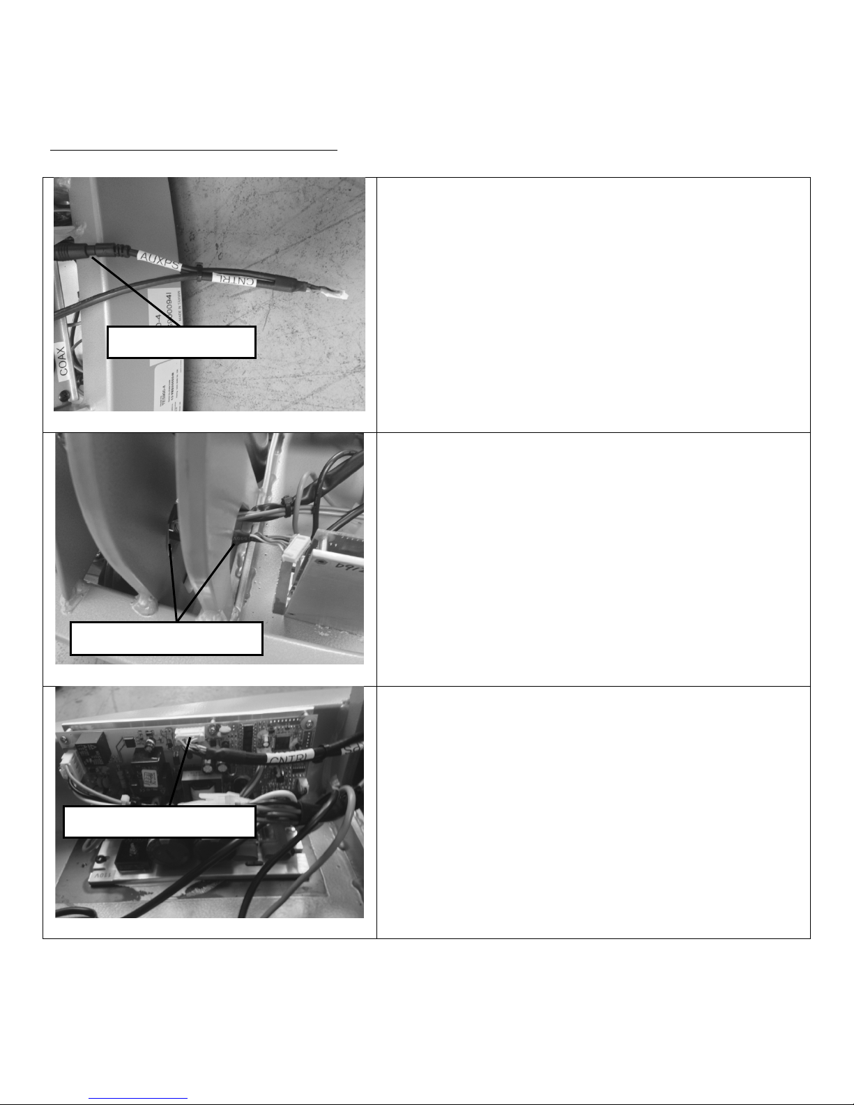
CHAPTER 2: ASSEMBLY INSTRUCTIONS
3-2B-1
a) Ensure the AUXPS cables that are attached to the CTRL
b) Route the CTRL cab le through the cutouts in both incline
c) Connect the CNTRL cable to the lower control board as
Ensure Connection
Route CTRL Cable Here
Connect CTRL Cable Here
TREADMILL ASSEMBLY STEPS (continued):
Step 3-2B Frame Cable Connections:
*9”TFT CONSOLES ONLY
cable are firmly connected as shown in picture 3-2B-1.
tower plates as shown in Picture 3-2B-2.
3-2B-2
shown in picture 3-2B-3.
3-2B-3
Truefitness.com / 800.426.6570 / 636.272.7100 17
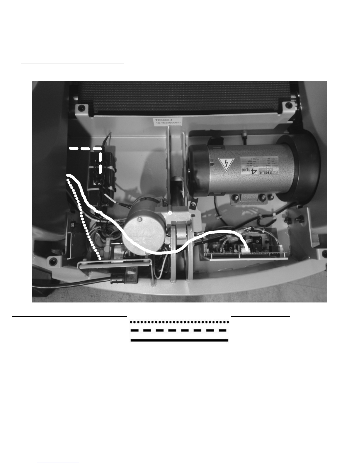
CHAPTER 2: ASSEMBLY INSTRUCTIONS
9” TFT Conso le:
Touchscreen & 15” TFT Console
TREADMILL ASSEMBLY STEPS (continued):
Frame Cable Routing Diagram:
Once all parts of step 3 are complete, the treadmill frame wiring should resemble the diagram below.
COAX & Network Cable
AUXPS
CNRL Cable
Truefitness.com / 800.426.6570 / 636.272.7100 18
COAX & Network Cable
N/A
AUXPS/ CNRL Cable bundle
CHAPTER 2: ASSEMBLY INSTRUCTIONS
TREADMILL ASSEMBLY STEPS (continued):
Step 4 Pedestal Hardware and Motor Cover:
a) Rotate Pedestal – R (D) upright as shown in Fig 4.
b) Using 5/16 inch hex key, install, but do not tighten, two per side of Bolt 3/8-16 UNC x 5-1/2 (b) and Washer 3/8
Split (a) into front of Frame as shown in Fig. 4.
Fig. 4
c) Remove ribs (right and left side) on Motor Cover as indicated by arrow in Fig. 4-1. Discard tabs.
NOTE: Hold inner portion of motor cover shown on right side of Fig. 4-1. Wiggle left side up and down until
tab breaks on right side. Then grasp tab and wiggle until it breaks free. Repeat for right side of motor cover.
d) Install Motor Cover using hardware; flat washer (n), screw (o), and then Cap – Motor Cover (p
).
Truefitness.com / 800.426.6570 / 636.272.7100 19
CHAPTER 2: ASSEMBLY INSTRUCTIONS
TREADMILL ASSEMBLY STEPS (continued):
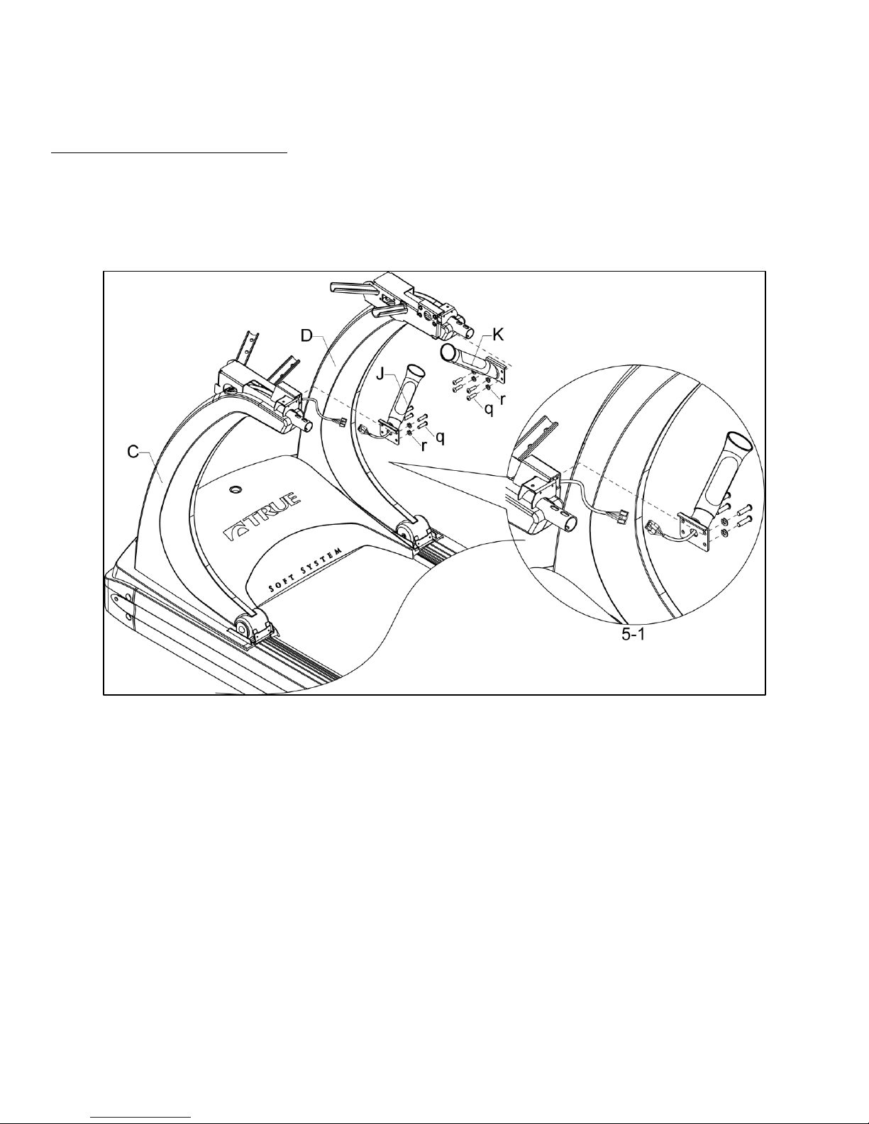
Step 5 Hand Grip Assemblies:
a. Connect the wires coming from the bottom of the hand grip assemblies (J, K) to the
corresponding wires located in the pedestal arms (D, C) as shown in figure 5-1.
b. Secure the hand grip assemblies (J, K) to the pedestal arms (D, C) with four screws (q) and four
spring washers (r) on each side.
Fig. 5
.
Truefitness.com / 800.426.6570 / 636.272.7100 20
CHAPTER 2: ASSEMBLY INSTRUCTIONS
Step 4 Bolts
Step 2 Bolts
Pedestal Tubing Cradle
Fig. 6
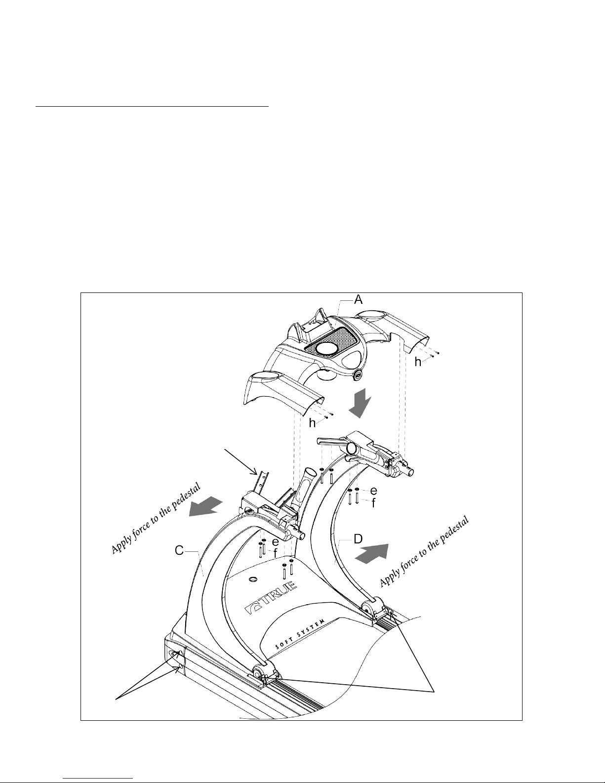
TREADMILL ASSEMBLY STEPS (continued):
Step 6 Console Rack and Secure Pedestals:
a) Install Console Rack (A) onto Pedestals R & L by resting Console Rack tubing on top of Pedestal tubing cradles.
NOTE: Force may need to be applied to the inside of the pedestals (C, D). Spreading the pedestals apart helps
to ensure accurate console rack placement.
CAUTION: Do not pinch cabling during this step.
b) Install 2 screws (h) under each side of the console rack (A) but do not tighten.
c) Using 3/16 inch hex key, install, but do not tighten, eight Bolts 5/16-24 UNF x 1-1/2 (e) and external tooth
washers M8 (d) through Pedestal tubing nest and into Console Rack. You may need to align Pedestal and Console
Rack to install first bolt on right and left side.
d) Tighten 4 screws (h) from STEP 6b.
e) Tighten 8 bolts (f) from STEP 6c.
f) Tighten 2 bolts from STEP 2, Bolt 3/8-16 UNC x 3/4 (c) at pivot point of Pedestal.
g) Tighten 4 bolts from STEP 4, Bolt 3/8-16 UNC x 4-1/2 (b) at front of frame.
Truefitness.com / 800.426.6570 / 636.272.7100 21
CHAPTER 2: ASSEMBLY INSTRUCTIONS
TREADMILL ASSEMBLY STEPS (continued):
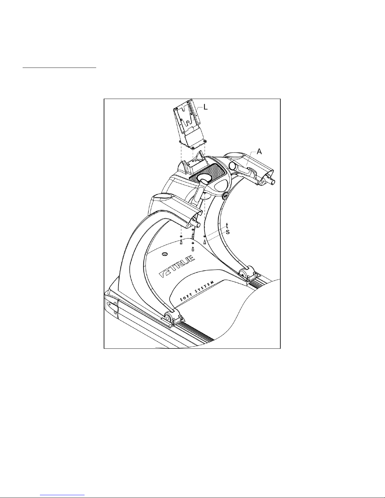
Step 7 Console Mast:
a) Insert the console mast (L) into the console rack and secure it with 4 screws (s) and 4 spring washers (t), but do not
tighten the screws completely until they have all been installed.
Truefitness.com / 800.426.6570 / 636.272.7100 22
Fig. 7
CHAPTER 2: ASSEMBLY INSTRUCTIONS
Right Grip Assembly
DC Power
Right Grip
DC Power
Network
Network
Main Data Cable
Coax Cable
Main Data Cable
Coax Cable
Left Grip Assembly
9-1
TREADMILL ASSEMBLY STEPS (continued):
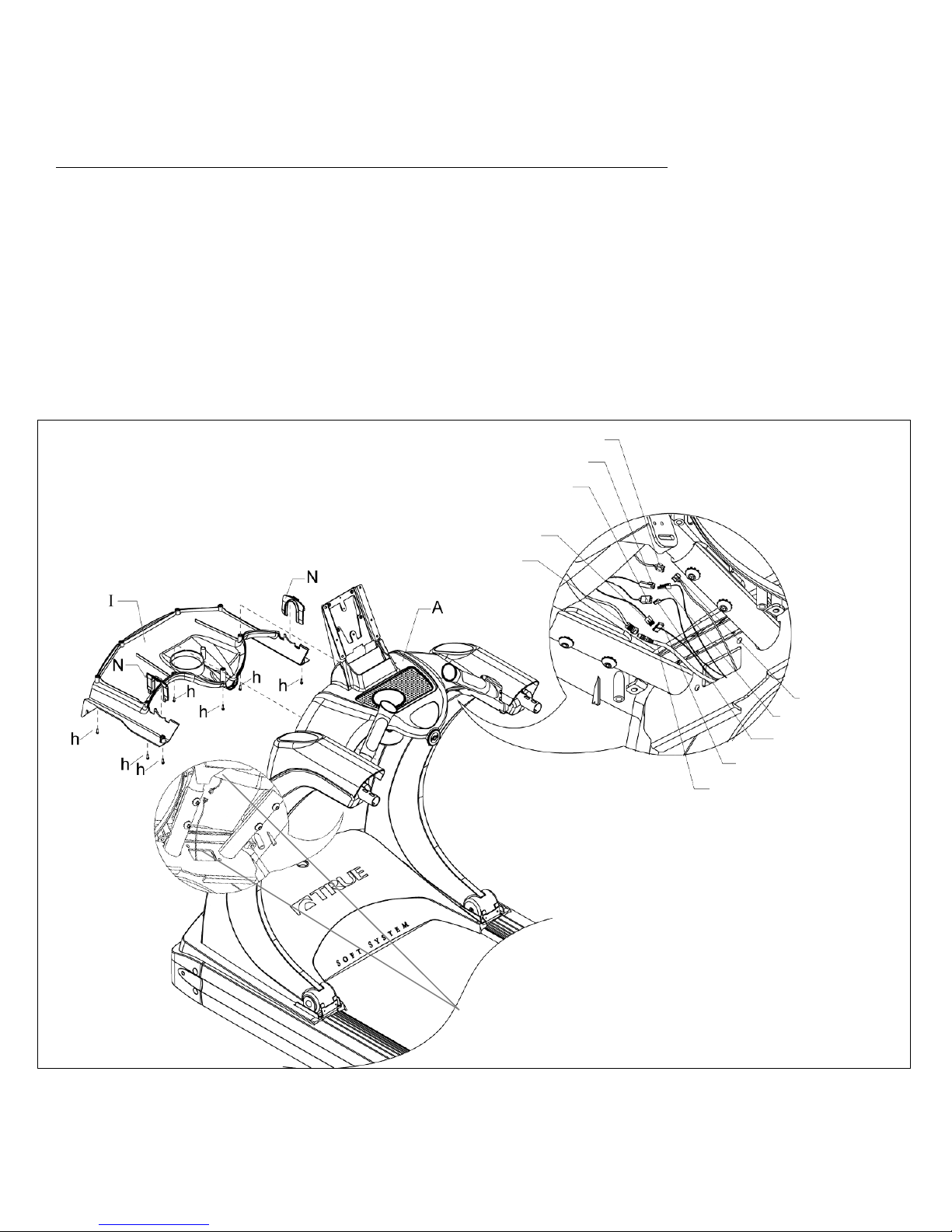
Step 8 Console Rack Cable Connections and Lower Cover Installation:
a. Connect all wires from the right pedestal arm to the wires from the upper console rack cover (A) as
shown in figure 9-1(all cables will be connected regardless of console option).
*Do not over torque the coax TV cable.
b. Fit all cables securely into the underside of the upper console rack cover (A).
c. Install the hand grip base covers (N) into the upper console rack cover (A).
d. Install the lower console rack cover (I) using eight screws (h), but do not tighten completely.
e. Adjust the placement of the hand grip base covers to ensure the correct fit while taking care not to pinch
any wires
f. Tighten the screws (h).
Truefitness.com / 800.426.6570 / 636.272.7100 23
Fig. 8
CHAPTER 2: ASSEMBLY INSTRUCTIONS
TREADMILL ASSEMBLY STEPS (continued):
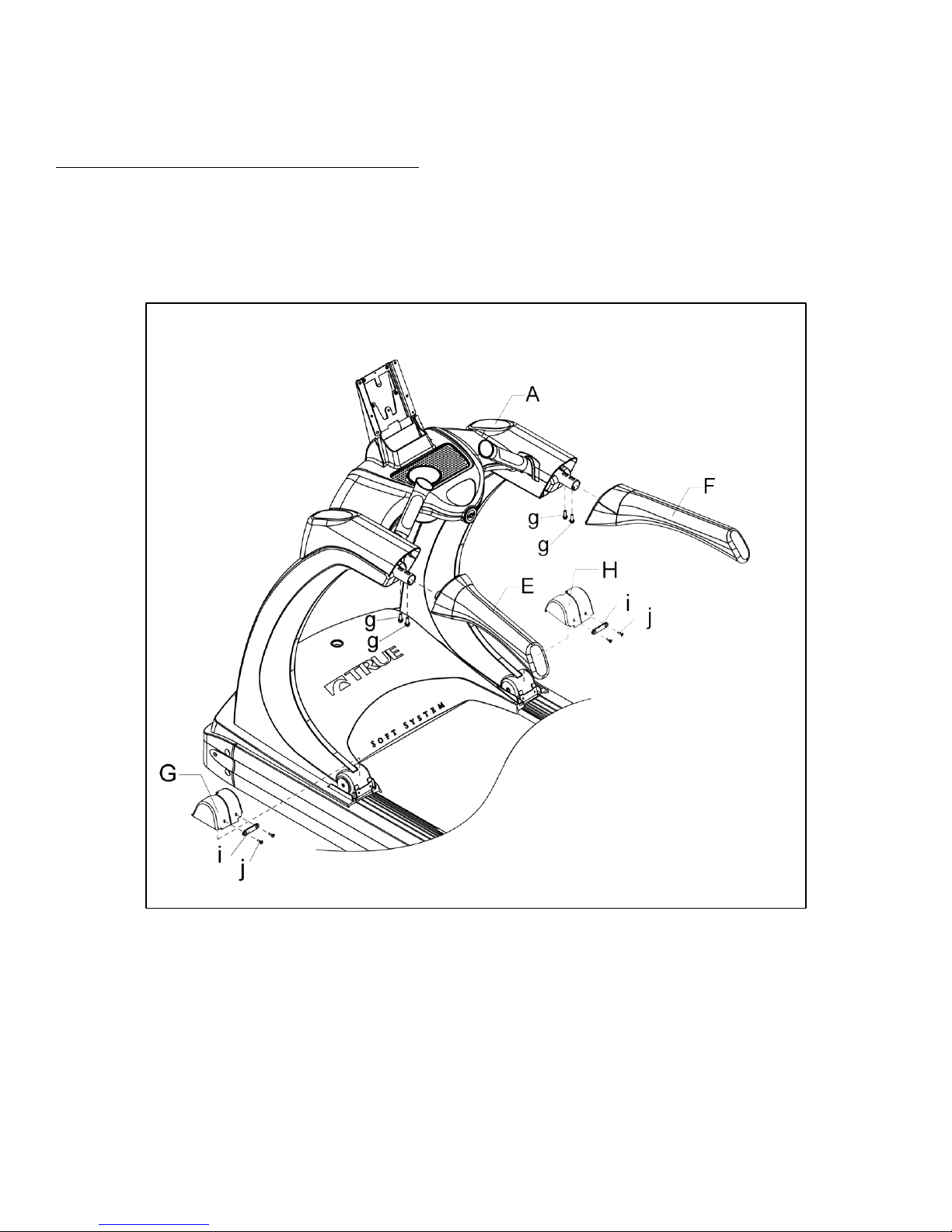
Step 9 Handrail & Pivot Trim Installation:
a) Insert Handrails (E, F) into Pedestals by slightly rotating Handrail and pushing front rubber lip of Handrail under
the Pedestal plastic.
b) Secure Handrails with bolts (g, 2 per side).
c) Install Pivot Trim Left & Right (G, H) onto Frame as shown in Fig. 9. Insert front tab of Pivot Trim into Motor
Cover side piece and then rotate down to cover pivot. Secure with Strap – Pedestal Trim (i) and two Screws 10-32
(j) using #2 Phillips screwdriver.
Truefitness.com / 800.426.6570 / 636.272.7100 24
CHAPTER 2: ASSEMBLY INSTRUCTIONS
CLIP
MAGNET
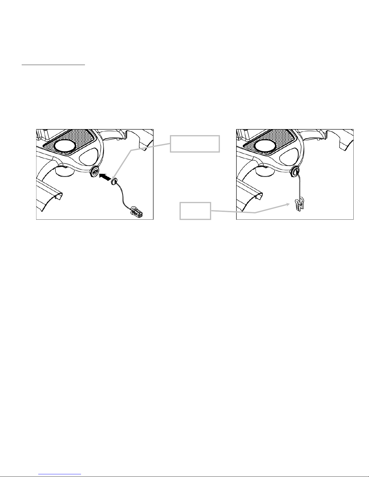
TREADMILL ASSEMBLY STEPS (continued):
Step 10 Safety Key:
a) Safety key and attachment cord are wrapped around plate during shipping.
b) Unwind safety key and cord from plate.
c) Attach Safety Key magnet to front of console rack as shown below.
d) Attach Safety Key clip to plate located on Console Rack (when not working out).
e) Attach clip to clothing at the beginning of any workout.
CAUTION: Read treadmill Owner’s Manual before attempting any workout
Truefitness.com / 800.426.6570 / 636.272.7100 25
CHAPTER 2: ASSEMBLY INSTRUCTIONS
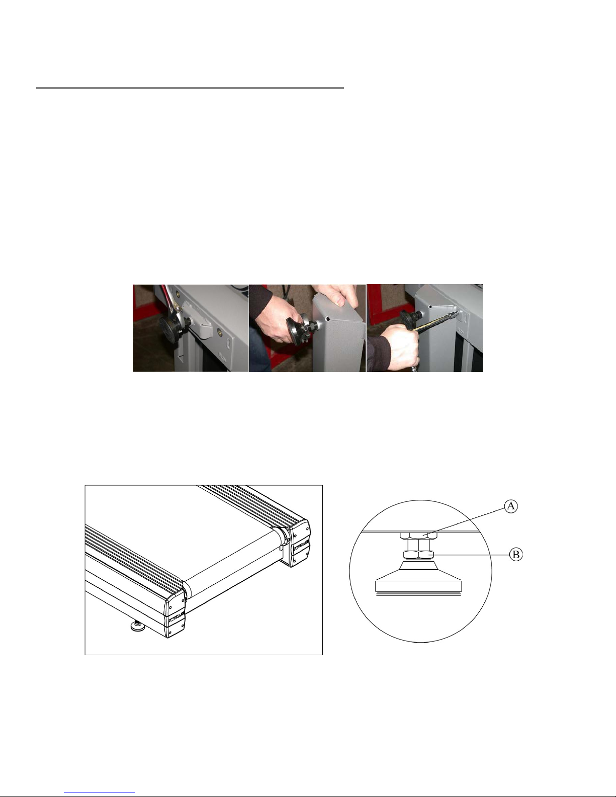
Step 11 Decline Foot Assembly Installation & Leveling:
a) Position cardboard from packaging next to side of base unit.
b) Using 2 people, tilt treadmill on one side so that cardboard protects side of unit.
c) While one person holds treadmill securely in place, the other person must unscrew both rear leveling feet. Place to
side for later use. See Fig. 1.
d) Install two leveling feet on decline foot assembly, with leveling foot with extra jam nut to be placed on the shorter
post of decline foot assembly. See Fig 2.
e) Install Decline Foot Assembly onto existing foot mounts of treadmill frame. Align two grooves in Decline Foot
Assembly with two grooves in treadmill frame bottom. They should both be on the left side of the base unit.
Ensure that you leave approximately 1/4 inch gap between the jam nut and the base of the decline foot on the right
side of the pedestal. See Fig. 3.
f) Secure with four 1/4-20 x ¾ hex head bolts included in kit.
g) Using 2 people, carefully tilt treadmill upright.
Fig 1 Fig 2 Fig 3
h) Ensure treadmill incline rack wheels and rear feet are resting on the floor and not on cardboard,
packaging, etc.
i) Using a 15/16 inch open end wrench, loosen nut A on Right Rear Foot (only side adjustable). Fig. 12-2
j) Using a level or estimating by sight, turn section B of foot clockwise, or counter-clockwise, using a 7/8 inch open
end wrench to level the rear of treadmill.
k) Tighten nut A until it is secured against bottom of treadmill.
Fig. 12-1 Fig. 12-2
NOTE: The protective film covering the frame sides and front can be removed at this time.
Truefitness.com / 800.426.6570 / 636.272.7100 26
 Loading...