

True Fitness CS400 Owner's Manual

* Assembly Guide & Warranty Card Included
CS400 UPRIGHT BIKE
OWNER’S MANUAL
Revision 122613

CS400 UPRIGHT BIKE OWNERS MANUAL
IMPORTANT:
All Products shown are prototype. Actual product delivered may vary.
Product specifications, features & software are subject to change without notice.
For the most up to date owner’s manual please visit www.truefitness.com.
For documents in additional languages please visit www.truefitness.com/document-library/29/international-manuals
IMPORTANTE:
Todos los productos mostrados son prototipos. La realidad el producto suministrado puede diferir.
Especificaciones de productos, características y software están sujetas a cambios sin previo aviso.
Para la más actualizada de este manual del propietario, por favor visite www.truefitness.com
Para los documentos en otros idiomas, por favor visite www.truefitness.com/document-library/29/international-manuals
IMPORTANT:
Tous les produits présentés sont prototype. Le produit réel livré peut varier.
Spécifications du produit, caractéristiques et logiciels sont sujettes à modification sans préavis.
Pour la plus à jour le manuel du propriétaire s'il vous plaît visitez www.truefitness.com.
Pour
documents dans des langues supplémentaires, veuillez www.truefitness.com/document-library/29/international-manuals de visite
重要提示:
显示所有产品的原型。实际交付的产品可能有所不同
产品规格,功能和软件如有更改,恕不另行通知
迄今为止对于大多数的使用说明书,请访问www.truefitness.com
对于其他语言的文档,请访问www.truefitness.com/document-library/29/international-manuals
:مﺎھ
ﻊﯾﻣﺟ تﺎﺟﺗﻧﻣﻟا ﻲھ ﺔﺿورﻌﻣﻟا جذوﻣﻧﻟا .فﻠﺗﺧﺗ دﻗ ﻲﻠﻌﻔﻟا ﺞﺗﻧﻣﻟا .ﺎﮭﻣﯾﻠﺳﺗ
و ،ﺞﺗﻧﻣﻟا تﺎﻔﺻاوﻣ ﺞﻣارﺑﻟاو تازﯾﻣﻟارﯾﯾﻐﺗﻠﻟ ﺔﻠﺑﺎﻗ رﺎﻌﺷإ نود.
ﻟ لﺻﯾ ﺎﻣ مظﻌﻣنﻵا ﻰﺗﺣ كﻟﺎﻣﻟا لﯾﻟد ةرﺎﯾز ﻰﺟرﯾ
www.truefitness.com.
تادﻧﺗﺳﻣﻠﻟ تﺎﻐﻟ ﻲﻓ ﻰﺟرﯾ ،ﺔﯾﻓﺎﺿإ ةرﺎﯾز
WICHTIG:
Alle hier gezeigten Produkte sind Prototypen. Das tatsächliche Produkt ausgeliefert wird, kann variieren.
Produkt-Spezifikationen, Funktionen und Software können sich ohne vorherige Ankündigung ändern.
In den meisten Fällen bis zu Bedienungsanleitung Bisher besuchen Sie bitte www.truefitness.com.
Für Dokumente in weiteren Sprachen finden Sie unter www.truefitness.com/document-library/29/international-manuals
BELANGRIJK:
Alle getoonde producten zijn prototype. Daadwerkelijke product geleverd kan verschillen.
Product specificaties, eigenschappen & software zijn onderhevig aan verandering zonder kennisgeving.
Voor de meest actuele handleiding van de eigenaar kunt u terecht www.truefitness.com.
Voor documenten in andere talen kunt u terecht op www.truefitness.com/document-library/29/international-manuals
ВАЖНО:
Все товары указаны прототипа. Фактический продукт, поставляемый могут отличаться.
Технические характеристики, особенности и программного обеспечения могут быть изменены без предварительного
уведомления.
Для получения самой последней на сегодняшний день руководство по эксплуатации пожалуйста, посетите
www.truefitness.com
.Для документов на другие языки, пожалуйста, посетите www.truefitness.com/document-library/29/international-manuals
www.truefitness.com/document-library/29/international-manuals
Truefitness.com / 800.426.6570 / 636.272.7100

CS400 UPRIGHT BIKE OWNERS MANUAL
Frank Trulaske, founder and CEO of TRUE, has had the same simple philosophy of delivering superior products, service
and support for over 30 years. Today, TRUE is the global leader in premium cardio equipment for the commercial and
residential markets. Our goal is to be the leader in technology, innovation, performance, safety and style. TRUE has
received many awards for its commercial and retail product over the years and remains the benchmark for the industry.
Fitness facilities and consumers invest in TRUE products for their durable commercial platforms used in all its cardio
products, both commercial and residential alike.
The proud manufacturing tradition of quality and the culture of innovation at TRUE have given rise to a full line of
truly extraordinary treadmills, indoor cycles and elliptical cross-trainers. As a result, people all over the world are
benefiting from the TRUE experience. Innovation across the full product line has made TRUE successful and is a
trademark of the TRUE heritage. TRUE’s patented Heart Rate Control® technology is just one of the remarkable ways we
deliver simple and superior performance every user can enjoy, and most importantly, use to achieve personal health and
fitness goals.
TRUE strives to perfect biomechanically correct and orthopedically comfortable, functional products. Whether it be the
mesh seat in the recumbent bike, the Soft Step® in the elliptical cross-trainers or the Soft System® in our treadmills, we
deliver the best.
At the heart of our success is the relentless and systematic life testing of both our products and their components. We
have dedicated employees who understand our philosophy is to deliver the best products in the world.
Our goal is not to sell the most cardio products in the world, but to deliver the world’s best premium equipment for our
customers’ health and fitness solutions.
To own a TRUE machine is to be part of an exclusive fitness community that delivers results – your results.
Thank you for becoming a part of the TRUE experience.
TRANSCEND ALL OTHERS!
Truefitness.com / 800.426.6570 / 636.272.7100

CS400 UPRIGHT BIKE OWNERS MANUAL
Chapter 1: Safety Instructions
TABLE OF CONTENTS
Safety Instructions 1
Space Requirements 3
Grounding Instructions 4
Power Requirements 5
Warning Decals 6
Compliances 6
Chapter 2 Assembly Instructions
Pre-Assembly Checklist 7
Assembly Steps 9
Chapter 3: Product Overview
Bike Overview 29
Chapter 4: Programming & Operation
Heart Rate Monitoring 31
Heart Rate Control 31
Program Descriptions 33
Virtual Active® Videos 37
Chapter 4A: Transcend Operation
Transcend Overview 39
Touchscreen Introduction 41
Touchscreen Navigation 41
iPod® Integration 47
TV Controls 48
Virtual Active® 49
Netpulse® 49
Advanced Console Functions 50
:
Chapter 4B: Escalate9 Operation
Escalate 9 Overview 65
Console Navigation 67
Advanced Console Functions 73
Chapter 4C: Emerge Operation
Emerge Overview 82
Console Navigation 84
Advanced Console Functions 86
Chapter 5: Care & Maintenance
Care & Maintenance 90
Cleaning the Equipment 90
Lubrication 90
Other Scheduled Preventive Maintenance 91
Long Term Storage 91
Chapter 6: Customer Service
Contacting Service 92
Contacting Sales 92
Reporting Freight Claims or Parts Damage 93
Chapter 7: Additional Information
Troubleshooting 94
Specification Sheet 97
Warranty Information 99
Truefitness.com / 800.426.6570 / 636.272.7100

CHAPTER 1 SAFETY INSTRUCTIONS
IMPORTANT SAFETY INSTRUCTIONS
SAVE THESE SAFETY INSTRUCTIONS
This bike is intended for commercial or institutional setting. This owner’s manual should be accessible to all personal
trainers, staff members, and members.
WARNING: All EXERCISERS MUST READ ALL INSTRUCTIONS BEFORE USING THE BIKE.
WARNING: Heart rate monitoring systems may be inaccurate for some individuals. Over-exercising may result in
serious injury or death. If you feel faint, stop exercising immediately.
WARNING: Equipment should be immediately taken out of use if it fails to work properly or when a warning is
presented electronically.
TRUE STRONGLY recommends seeing a physician for a complete medical exam before undertaking an exercise program,
particularly if the user has a family history of high blood pressure or heart disease, is over the age of 45, smokes, has high
cholesterol, is obese or has not exercised regularly in the past year. Additionally, TRUE recommends consulting a fitness
professional on the correct use of this product. If at any time while exercising the user experiences faintness, dizziness,
pain or shortness of breath, he or she must stop immediately.
WARNING: To reduce the risk of electrical shock, always unplug this TRUE product before cleaning or attempting any
maintenance activity. Do not handle the plug with wet hands.
WARNING: To reduce the risk of burns, fire, electric shock or injury, it is imperative to connect each product to a
properly grounded 110V electrical outlet. A risk of electrical shock may result from improper connection of the
equipment’s grounding conductor. Check with a qualified electrician if you are unsure about proper grounding
techniques. Do not modify the plug provided with this product. If it will not fit an electrical outlet, have a proper
outlet installed by a qualified electrician. Your TRUE Fitness product must be properly grounded to reduce risk of
shock if the bike malfunctions. Your bike is equipped with an electrical cord, which includes an equipment
grounding conductor and a grounding plug. The plug must be inserted into an outlet that has been properly
installed and grounded in accordance with all local codes and ordinances. A temporary adapter cannot be used to
connect this plug to a two-pole receptacle in North America. If a properly grounded 15 amp outlet is not available,
a qualified electrician must install one.
WARNING: Do not move the Equipment by lifting the console. Do not use the console as a handlebar during a workout.
WARNING: This product contains chemicals known to the state of California to cause cancer and birth defects or other
reproductive harm.
WARNING: Keep equipment stable on flat ground.
WARNING: Replace warning labels that may be worn, damaged or missing
WARNING: Replace any non-working or damaged components; remove the unit from service until repair is performed.
Truefitness.com / 800.426.6570 / 636.272.7100 1

CHAPTER 1 SAFETY INSTRUCTIONS
WARNING: To reduce the risk of burns, fire and electric shock or injury to persons, follow these instructions:
• This appliance should never be left unattended when plugged in.
• Do not use any type of extension cord with this product.
• Unplug it from the outlet when not in use and before any servicing.
• Do not operate the equipment while being covered with a blanket, plastic, or anything that insulates or stops
airflow.
CAUTION:
• Do not use typing or web surfing features at excessive speeds. Always stabilize yourself by holding a stationary
handle when using typing or web surfing features. (Varies by console option)
• Health related injuries may result from incorrect or excessive use of exercise equipment.
• Do not use the contact heart rate grips as a handlebar during a workout.
• Any changes or modifications to this equipment could void the product warranty.
• To disconnect plug remove from electrical outlet.
• The CS400 bike is self-generated and does not require the use of an electrical outlet with the LED console.
Optional TFT or touch screen consoles require 110V AC input and 9V DC 1.5Amp output for console operation
only.
• Use a TRUE AC power cord or AC/DC adapter only
• Note the plug configuration for the power adapter may vary by country.
• The batteries within self-generated equipment contain materials that are considered hazardous to the
environment. Federal law requires proper disposal of these batteries.
• Position this product so the power cord plug is accessible to the user.
• Keep the power cord away from heated surfaces. Do not pull the equipment by the power cord or use the cord as a
handle. Do not run the power cord along the side or under the Bike.
• If the bike power supply cord is damaged it must be replaced by the manufacturer, an authorized service agent, or
a similarly qualified person to avoid a hazard.
• Do not use this product in areas where aerosol spray products are being used or where oxygen is being
administered. Such substances create the danger of combustion and explosion.
• Always follow the console instructions for proper operation. Close supervision is necessary when used near
children under the age of 15, or disabled persons.
• Do not use this product outdoors, near water, while wet, or in areas if high humidity including extreme
temperature changes
• Never operate a TRUE product with the air openings blocked. Keep air openings free of lint, hair or any
obstructing material.
• Never insert objects into any openings in this product. If an object should drop inside, turn off the power, unplug
the power cord from the outlet and carefully retrieve it. If the item cannot be reached, contact TRUE Customer
Service.
• Never place liquids of any type directly on the unit except in the accessory tray or bottle holders. Containers with
lids are recommended.
• Wear shoes with rubber or high traction soles. Do not use shoes with heels, leather soles, cleats or spikes. Make
sure no stones are embedded in the soles. Do not use this product in bare feet. Keep all loose clothing, shoelaces
and towels away from moving parts.
• Do not reach into or underneath the unit, or tip it on its side during operation.
Truefitness.com / 800.426.6570 / 636.272.7100 2

CHAPTER 1 SAFETY INSTRUCTIONS
CAUTION (continued):
• Use correct ergonomic positioning while operating the bike.
• Do not allow animals on or near the equipment while in operation.
• Do not exceed maximum user weight of 400 lbs (181 kg).
• Avoid exiting bike while the pedals are still in motion.
• Do use if you have a cold or fever.
• When using this exercise machine, basic precautions should always be followed.
• Use this bike only for its intended use as described in this manual.
• Do not use attachments not recommended by the manufacturer.
• Allow only trained personnel to service this equipment.
• Avoid the possibility of bystanders being struck or caught between moving parts by making sure that they are out
of reach of the bike while it is in motion.
• Allow only one person at a time on the bike while it’s operating.
• It is the sole responsibility of the owner/operator to ensure regular and scheduled maintenance is performed.
• This appliance can be used by children aged from 8 years and above and persons with reduced physical, sensory or
mental capabilities or lack of experience and knowledge if they have been given supervision or instruction
concerning use of the appliance in a safe way and understand the hazards involved.
• Children shall not play with the appliance.
• Cleaning and user maintenance shall not be made by children without supervision.
SPACE REQUIREMENTS:
• TRUE’s recommendation is to leave a 39” safety zone at rear of bike. The sides of the bike should be at least 20”
away from the wall or obstructions. (See Fig 1)
Truefitness.com / 800.426.6570 / 636.272.7100 3

CHAPTER 1 SAFETY INSTRUCTIONS
GROUNDING INSTRUCTIONS:
This product must be grounded, If it should malfunction or breakdown, grounding provides a path of least resistance for electric
current to reduce the risk of electric shock. This product is equipped with a cord having an equipment-grounding conductor and
a grounding plug. The plug must be plugged into an appropriate outlet that is properly installed and grounded in accordance with
all local codes and ordinances.
DANGER:
Improper connection of the equipment-grounding conductor can result in a risk of electric shock.
•
Check with a qualified electrician or serviceman if you are in doubt as to whether the product is properly grounded. Do
•
not modify the plug provided with the product – if it will not fit the outlet; have a proper outlet installed by a qualified
electrician.
Do not remove any covers or you may risk injury due to electric shock.
•
• The 120-V model is for use on a nominal 120-V circuit and has a grounding plug that looks like the plug
illustrated in figure A. Make sure the product is connected to an outlet having the same configuration as the plug.
No adaptor should be used with this product.
• The 230-V model is for use on a circuit having a nominal rating more than 120-V and is factory-equipped with a
specific electric cord and has a grounding plug that looks like the plug illustrated in figure B. Make sure that the
product is connected to an outlet having the same configuration as the plug in Figure B. No adapter should be
used with this product. If the product must be reconnected for use on a different type of electric circuit, the
reconnection should be made by qualified service personnel.
Truefitness.com / 800.426.6570 / 636.272.7100 4

CHAPTER 1 SAFETY INSTRUCTIONS
Truefitness.com / 800.426.6570 / 636.272.7100 5

CHAPTER 1 SAFETY INSTRUCTIONS
WARNING DECALS:
WARNING: Replace warning labels that may be worn, damaged or missing.
To replace any worn or missing warning decals contact TRUE FITNESS by one of the following: www.truefitness.com or
contact customer service at 800-883-8783.
COMPLIANCES:
This equipment complies with all applicable codes and regulations. For a complete list of compliances, please visit
www.truefitness.com
Truefitness.com / 800.426.6570 / 636.272.7100 6
CHAPTER 2: ASSEMBLY INSTRUCTIONS
CAUTION:
• Read and understand all instructions and warnings prior to use.
• Obtain a medical exam before beginning any exercise program. If at any time during exercise you feel faint, dizzy,
or experience pain, stop and consult your physician.
• Obtain proper instruction prior to use.
• Inspect the bike for incorrect, worn, or loose components and do not use until corrected, replaced, or tightened
prior to use.
• Do not wear loose or dangling clothing while using bike.
• Care should be used when mounting or dismounting bike.
• Disconnect all power (if applicable) before servicing bike.
• Do not exceed maximum user weight of 400 lbs.
• Keep children and animals away.
• Use caution when moving and assembling bike.
• All exercise equipment is potentially hazardous. If attention is not paid to the conditions of equipment usage,
death, or serious injury could occur.
• Save these instructions.
*Should you need technical assistance in assembly of your TRUE Fitness product, contact TRUE Fitness Technical
Support at 1-800-883-8783.
PRE-ASSEMBLY CHECK LIST:
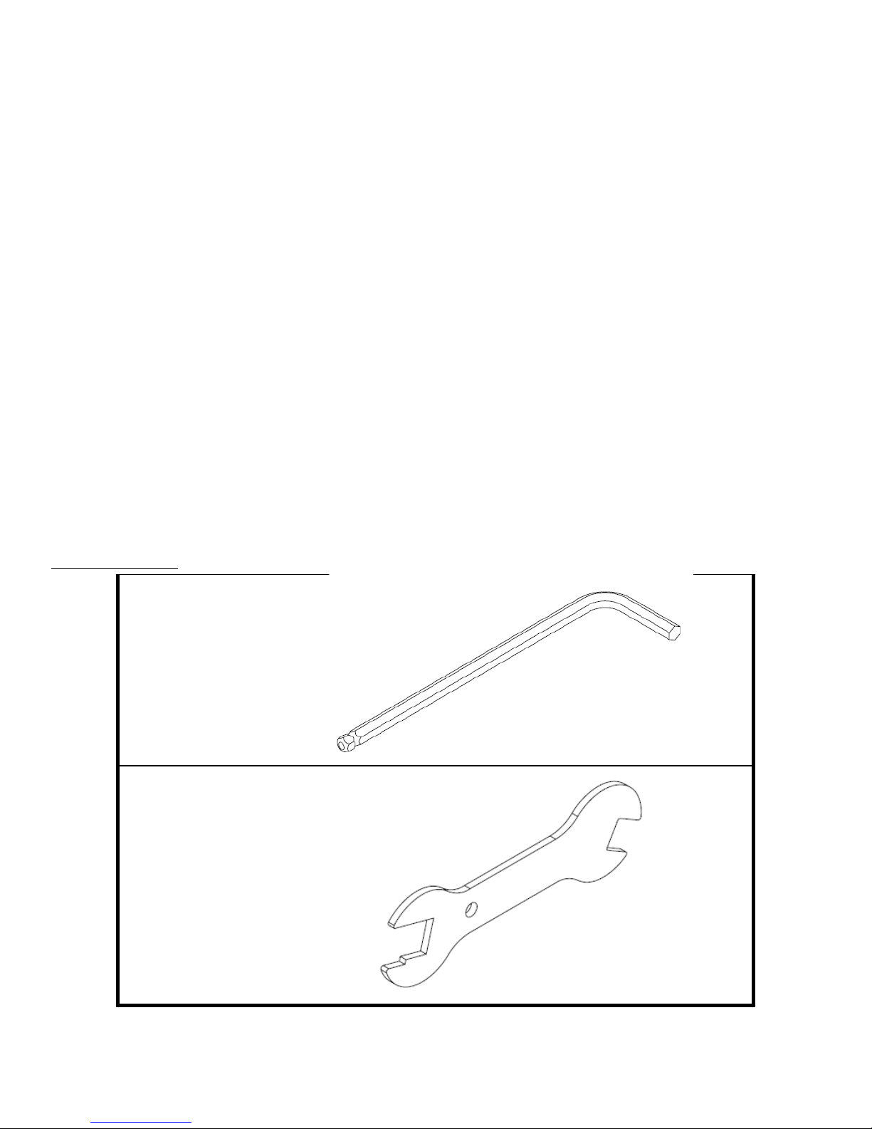
Provided Tools:
HEX WRENCH
(6MM)
WRENCH
(COMBINATION
13/15/17MM)
NOTE: Phillips Head Screwdriver) is NOT provided
Truefitness.com / 800.426.6570 / 636.272.7100 7
CHAPTER 2: ASSEMBLY INSTRUCTIONS
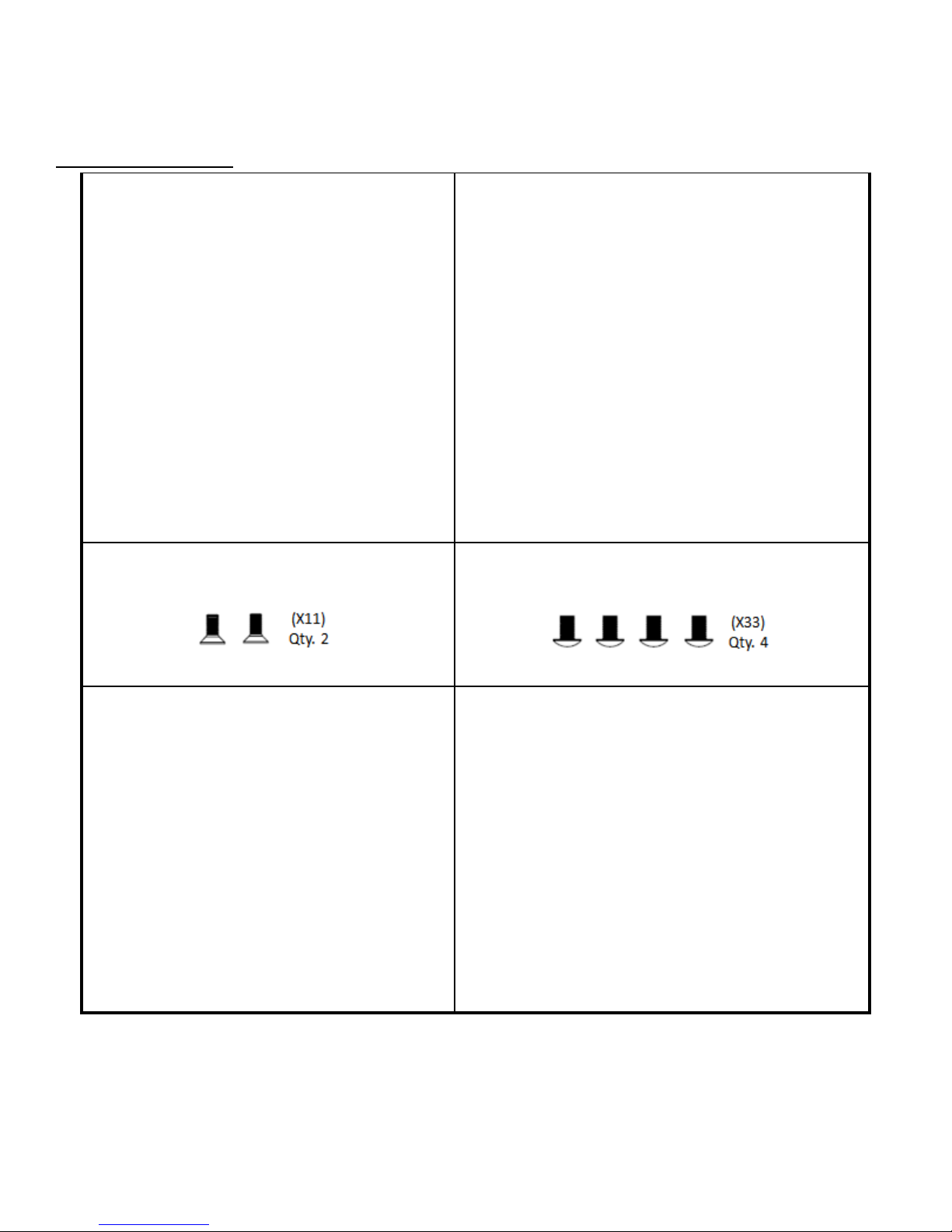
PRE-ASSEMBLY CHECK LIST (CONTINUED):
Provided Hardware:
STEP 1 & 2 (FRONT & REAR STABILIZER BARS) STEP 5 (FRONT MAST)
STEP 6 (MAST BOOT) STEP 11 (STORAGE TRAY)
STEP 8 (HANDLEBAR) STEP 12 (CONSOLE COVERS)
Truefitness.com / 800.426.6570 / 636.272.7100 8

CHAPTER 2: ASSEMBLY INSTRUCTIONS
BIKE ASSEMBLY STEPS:
CAUTION:
• Use caution when assembling bike. It is recommended that at least two people unpack and assemble bike.
• Remove all bike components from packaging.
• For each step use hardware in the corresponding bag
Sub-Assembly Identification:
Use the image below as a reference for where the provided sub-assemblies will be located in the complete bike assembly:
Truefitness.com / 800.426.6570 / 636.272.7100 9
CHAPTER 2: ASSEMBLY INSTRUCTIONS
Tighten using the provided hex wrench
Tighten using the provided hex wrench
1a
1b
2a
2b
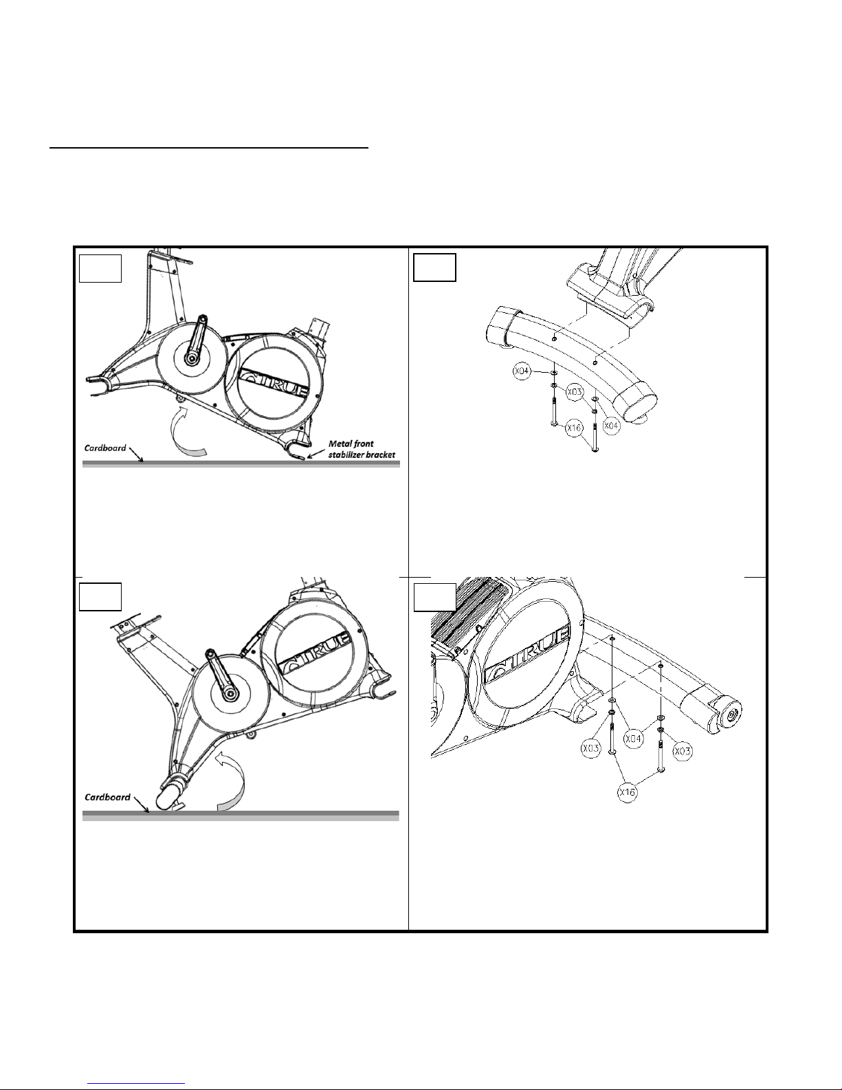
BIKE ASSEMBLY STEPS (continued):
Step 1 & 2 Front and Rear Stabilizer Bars:
CAUTION:
• It is recommended that at least 2 people are used to assemble the bike
• To protect the floor from damage, rest the bike frame on a large piece of cardboard packaging
• For each screw, install through split washer then
• Rotate the frame forward on the Front
Stabilizer bracket (metal)
• At least one person should hold the frame,
while another person completes the
remaining Rear Stabilizer installation steps
flat washer
• Insert Rear Stabilizer into the metal bracket
• Install each screw through the bottom of the metal
bracket, then through the Rear Stabilizer
•
• Rotate the frame backwards on the Rear
Stabilizer
• At least one person should hold the frame,
while another person completes the remaining
Front Stabilizer installation steps
Truefitness.com / 800.426.6570 / 636.272.7100 10
• For each screw, install through split washer then
flat washer
• Insert Front Stabilizer into the metal bracket
• Install each screw through the bottom of the metal
bracket, then through the Front Stabilizer
•
CHAPTER 2: ASSEMBLY INSTRUCTIONS
BIKE ASSEMBLY STEPS (continued):
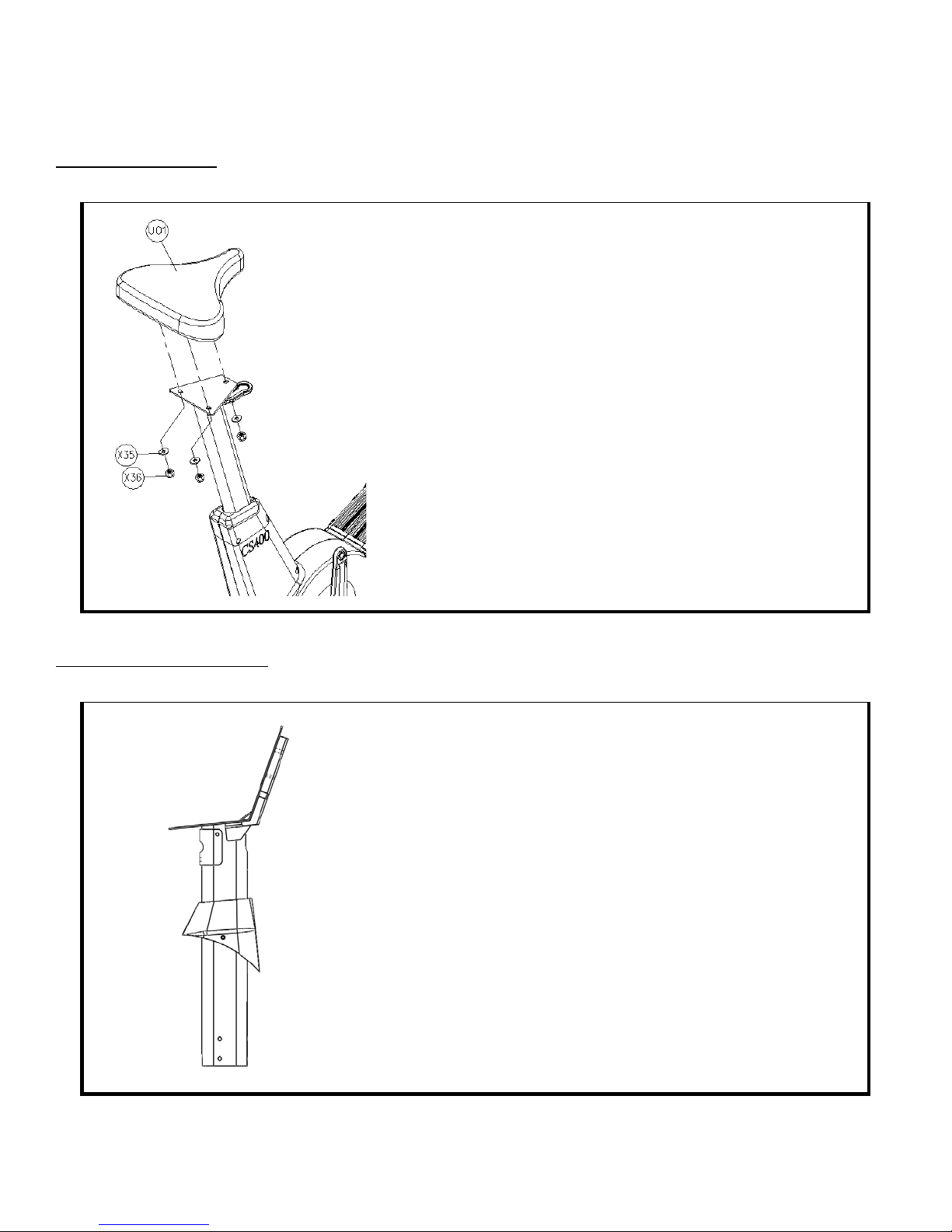
Step 3 Seat Saddle:
• Remove the flat washers and nuts from the 3 threaded rods on
the bottom of the Seat Saddle
• Insert Seat Saddle onto the Seat Post Mounting Plate; the
threaded rods on the bottom of the Seat Saddle will align with
the 3 openings on the Seat Post Mounting Plate
• For each threaded rod, install flat washer followed by nut
• Tighten using the provided wrench
Preparation for Step # 4:
• Install the Mast Boot component (including rubber gasket)
onto the Front Mast tube
• Verify that the Mast Boot is installed in the correct orientation
(reference the provided image, left)
Truefitness.com / 800.426.6570 / 636.272.7100 11

CHAPTER 2: ASSEMBLY INSTRUCTIONS
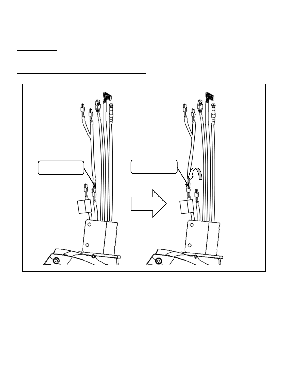
IMPORTANT:
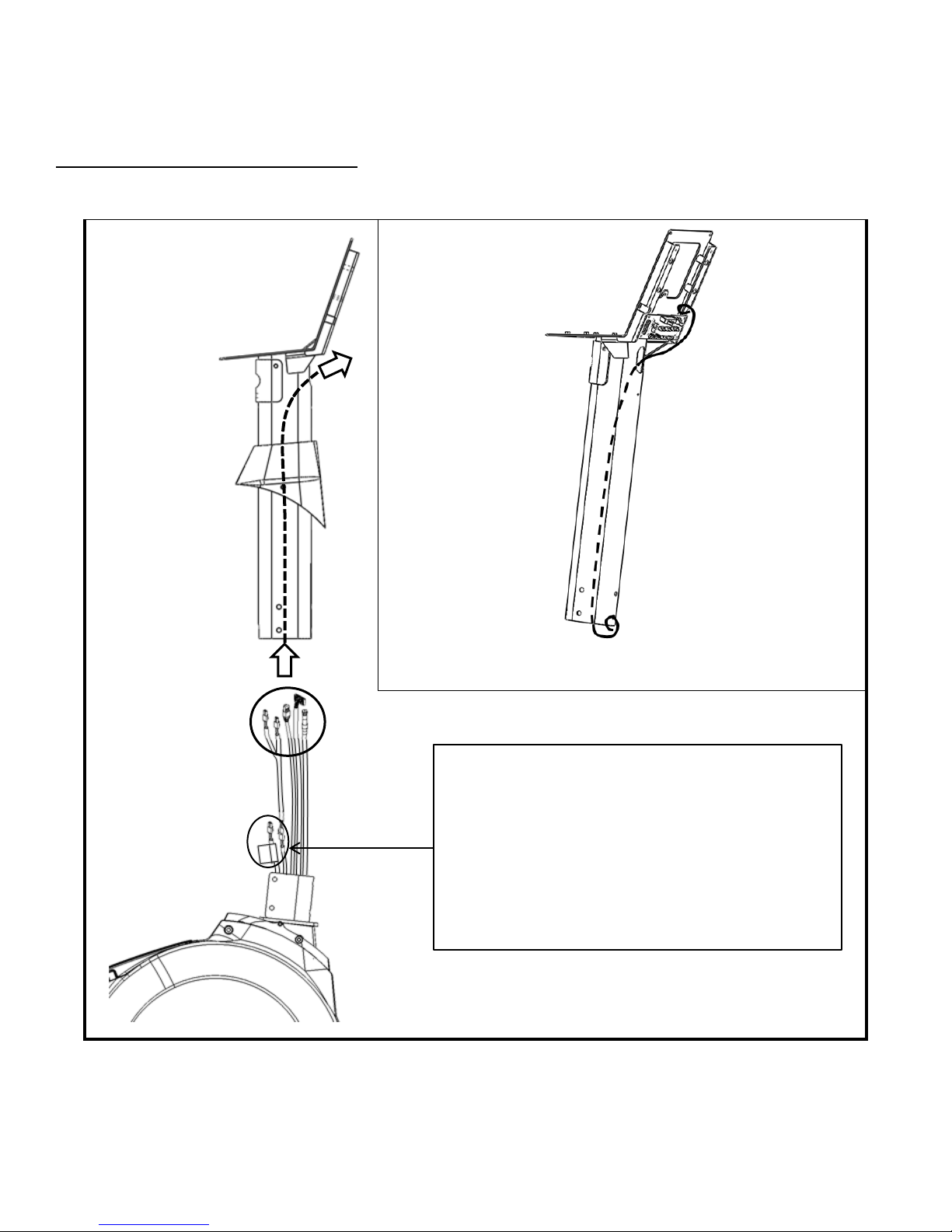
BIKE ASSEMBLY STEPS (continued):
Preparation for Step # 4 (continued):
Prior to Routing the Front Mast Cables, it is very important that the
following cable connection is confirmed.
If this connection is not made, the Console will not be able to turn on.
Truefitness.com / 800.426.6570 / 636.272.7100 12
CHAPTER 2: ASSEMBLY INSTRUCTIONS
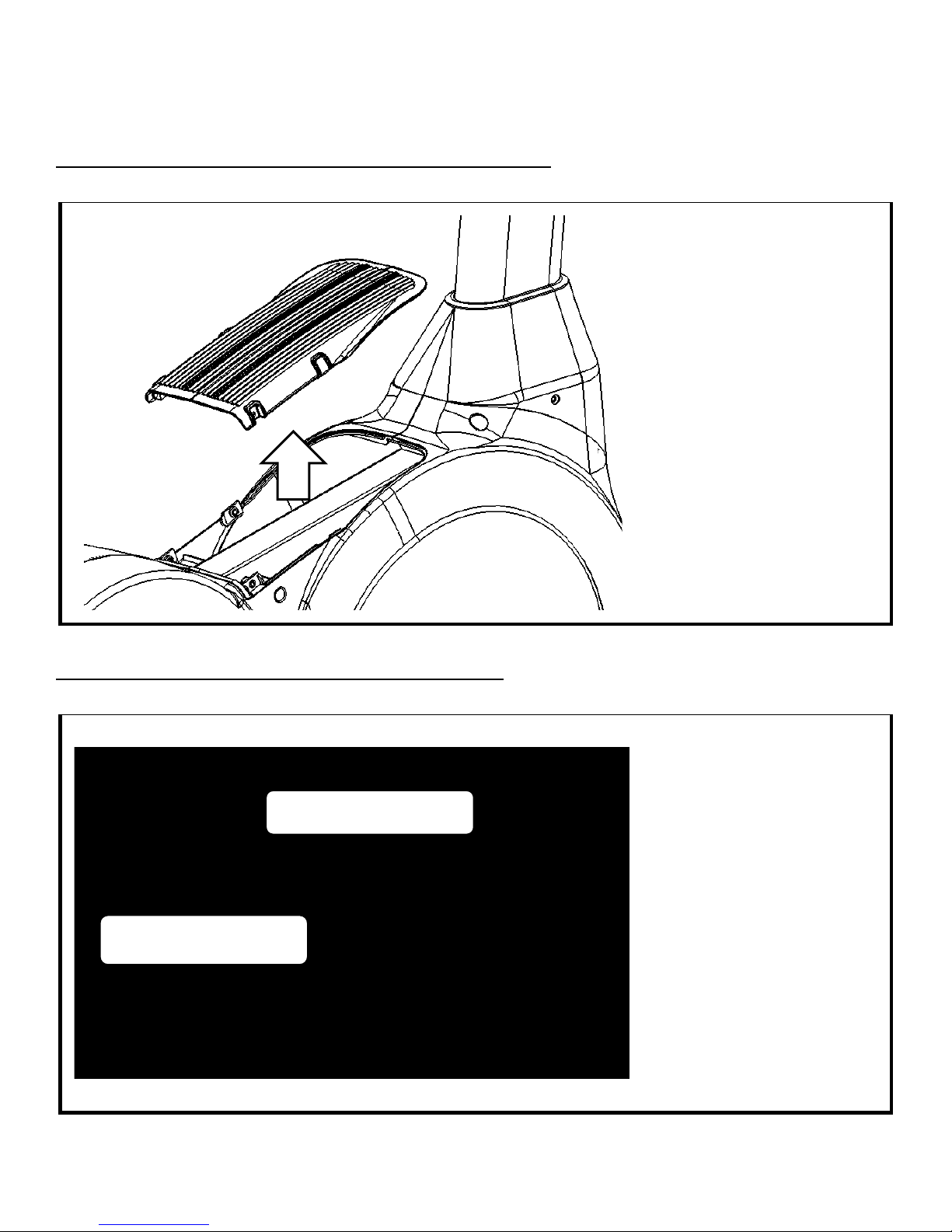
BIKE ASSEMBLY STEPS (continued):
Step #4 Front Mast Cable Routing:
*Complete the power supply installation on page 23 prior to completing this step if this unit will be paired with a
touchscreen or 15” TFT console.
Pull-tie provided with the front mast (see image, above)
NOTE: This connector is only used for the touchscreen
console installation.
If installing a touchscreen console, please refer to “Power
Supply Installation, Step A” before proceeding with
“Front Mast Cable Routing, Step # 4”.
Truefitness.com / 800.426.6570 / 636.272.7100 13
CHAPTER 2: ASSEMBLY INSTRUCTIONS
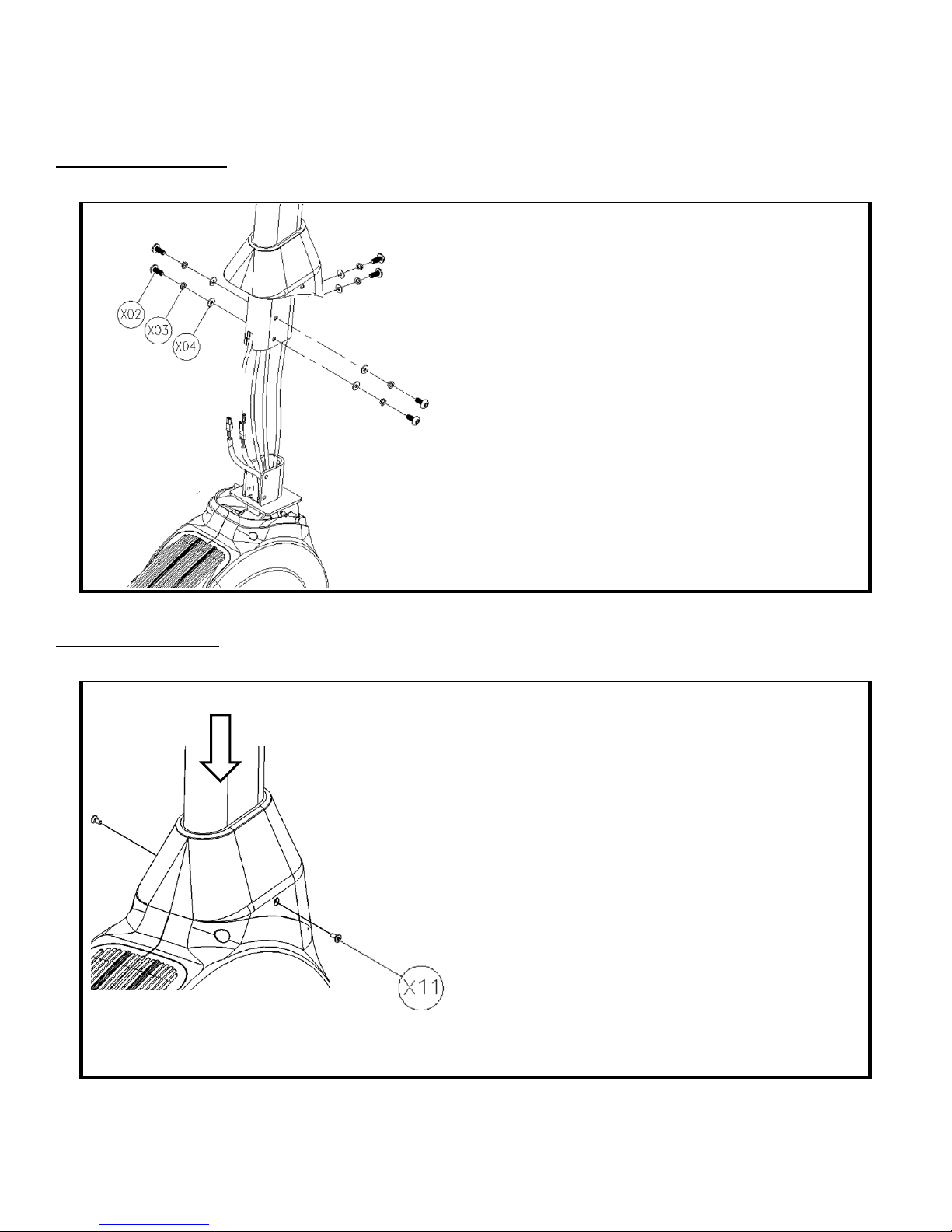
BIKE ASSEMBLY STEPS (continued):
Step #5 Front Mast:
• For each screw, install through split washer then flat
washer
• Insert the Front Mast onto exposed bike frame U-
bracket; pay special attention not to pinch any wires
between the Front Mast and the frame
• Verify that the Front Mast is in the correct
orientation (reference the provided image, left)
• Secure the Front Mast to the bike frame by
tightening all 6 screws with the provided hex wrench
• Verify that the Front Mast is secured tightly to the
bike frame; tighten screws if necessary
Step #6 Mast Boot:
• Pull down the Mast Boot
• Attach the Mast Boot to the plastic shrouds by
tightening both screw with a Phillips head
screwdriver (not provided)
Truefitness.com / 800.426.6570 / 636.272.7100 14
CHAPTER 2: ASSEMBLY INSTRUCTIONS
• At least one person should continue to hold the
remaining handlebar installation steps
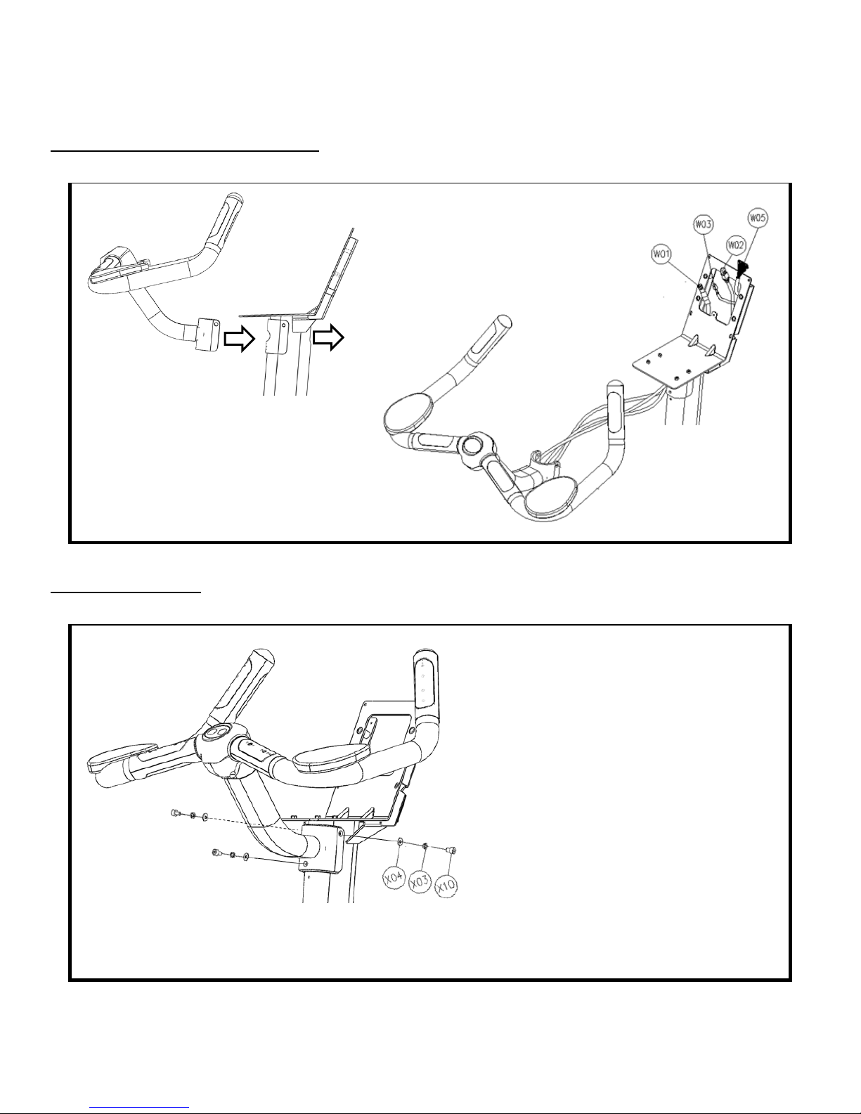
BIKE ASSEMBLY STEPS (continued):
Step #7 Handlebar Cable Routing:
• While at least one person holds the
Handlebar, another person should
direct the Handlebar Cables through the
Front Mast
Step #8 Handlebar:
Handlebar while another person completes the
• Insert the Handlebar U-bracket onto the
Front Mast; pay special attention that the
Handlebar Cables are pulled all the way
through the Front Mast, so that no cables
become pinched between the Handlebar
U-bracket and Front Mast
• For each screw, install through split
washer then flat washer
• Secure the Handlebar to the Front Mast
by tightening all 3 screws with the
provided hex wrench
• Verify that the Handlebar is secured
tightly to the Front Mast; tighten screws if
necessary
Truefitness.com / 800.426.6570 / 636.272.7100 15
CHAPTER 2: ASSEMBLY INSTRUCTIONS
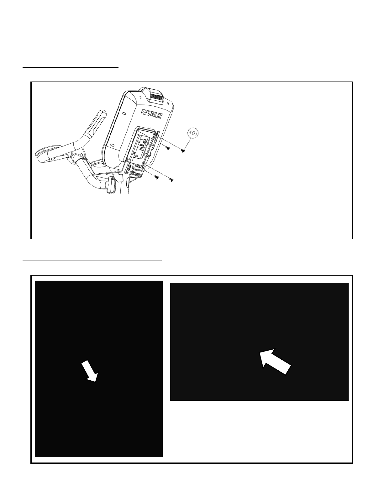
BIKE ASSEMBLY STEPS (continued):
Step #9 Console Mounting:
• The fasteners used to attach the Console are
provided in the Console packaging
• Align the back of the Console with the Front
Mast Console Mounting Plate
• Attach the Console to the Mounting Plate
by tightening all 4 screw with a Phillips head
screwdriver (not provided)
• At least one person should hold the Console while the
remaining Console mounting steps are completed
Step #10 Grounding wire Connections :
Truefitness.com / 800.426.6570 / 636.272.7100 16
• Remove Electronics Board ground wire screw (image, left)
• Re-attach both the Electronics Board ground wire and the
Console ground wire to the Front Mast Mounting Plate
using the same ground screw (image, above)

CHAPTER 2: ASSEMBLY INSTRUCTIONS
BIKE ASSEMBLY STEPS (continued):
Step #10 Electronics Board Cable Connections :
HANDLEBAR CABLE
CONNECTIONS:
• Telemetry HR
o 3-pin connector
• Right Thumb Switch
o 6-pin connector
o not used on CS400
• CHR_(L) & CHR_(R)
o Both 3-pin connector
o It is acceptable to install
either cable connector
into either Electronics
Board CHR location
FRONT MAST CABLE
CONNECTION:
• 20-pin Connector
Truefitness.com / 800.426.6570 / 636.272.7100 17
CHAPTER 2: ASSEMBLY INSTRUCTIONS
15” TFT
Console
10” Touchscreen
Console
NOTE:
All Ground Wires Must be connected
Power Cable
2 Pin
Network
Cable
Coaxial Cable
Data Cable
(50 Pin)
Ground Wire
Remove Warning Label
Do Not Use
BIKE ASSEMBLY STEPS (continued):
Step #10A Cable Connections (console):
*Follow Step 10A if installing a touchscreen console or 15”TFT console. For other consoles, proceed to Step 10B.
to access data port
Ethernet & Coaxial cable connections are not available on the Orange LED or 9” TFT Consoles
The Ethernet Port on the 15” TFT Console is non-functioning
Truefitness.com / 800.426.6570 / 636.272.7100 18
CHAPTER 2: ASSEMBLY INSTRUCTIONS
15” TFT
Console
10” Touchscreen
Console
All Ground Wires Must be connected
This connector is only used with
an “Optional TV Mount”
Ensure the Ground Cable is
Tuck excess Cable length into the
Front Mast
Do Not Use
BIKE ASSEMBLY STEPS (continued):
Step #10A Cable Connections (console):
*Follow Step 10A if installing a touchscreen console or 15”TFT console. For other consoles, proceed to Step 10B.
attached by the Ground Screw
*Location Varies By Model
NOTE: Ethernet & Coaxial cable connections are not available on the Orange LED or 9” TFT Consoles
The Ethernet Port on the 15” TFT Console is non-functioning
Truefitness.com / 800.426.6570 / 636.272.7100 19
CHAPTER 2: ASSEMBLY INSTRUCTIONS
9” TFT Console
Orange LED Console
BIKE ASSEMBLY STEPS (continued):
Step 10B Cable Connections (console):
*Follow Step 10B if installing a 9” TFT console or an LED console. For other consoles, return to Step 10A.
Connect Data Cable (50-pin)
Both 9” TFT & Orange LED Consoles
Connect Power Cable (2-pin)
9” TFT Console Orange LED Console
NOTE: Ethernet & Coaxial cable connections are not available on the Orange LED or 9” TFT Consoles
All Ground Wires Must be connected
Truefitness.com / 800.426.6570 / 636.272.7100 20
CHAPTER 2: ASSEMBLY INSTRUCTIONS
BIKE ASSEMBLY STEPS (continued):
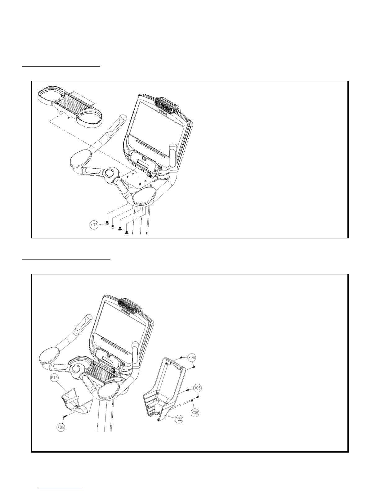
Step #11 Storage Tray:
• Insert the Storage Tray on top of the Front
Mast Mounting Plate; pay special attention to
make sure that the plastic lip of the Storage
Tray is tucked underneath the bottom of the
Console
• Attach the Storage Tray to the Mounting
Plate by tightening all 4 screw with a Phillips
head screwdriver (not provided)
Step #12 Console Covers:
• For all hardware, tighten using a Phillips
head screwdriver (not provided)
• Attach the Front Cover (P13) to the Front
Mast tube using a single (X06) fastener;
pay special attention to make sure the
Front Cover (P13) aligns with the Storage
Tray plastic around the Handlebar
• Align the Back Cover (P22) with the Front
Cover (P13) such that the plastic seams fit
together
• Attach the Back Cover (P22) to the
Console Mounting Plate using two (X06)
fasteners; top fastener hole locations
• Attach the Back Cover (P22) to the Front
Cover (P13) using two (X05) fasteners; the
longer fasteners
• Attach the Back Cover (P22) to the Front
Mast tube using the remaining single (X06)
fastener
Truefitness.com / 800.426.6570 / 636.272.7100 21

CHAPTER 2: ASSEMBLY INSTRUCTIONS
BIKE ASSEMBLY STEPS (continued):
Step #13 Pedals:
• Align the Left Pedal with the Left Crank
and the Right Pedal with the Right Crank;
pedals should be clearly labeled on the
Pedal Strap
• Secure each pedal to the appropriate
crank using the provided wrench
NOTE: The left pedal is reverse-threaded
(turn counter-clockwise to tighten)
Step #14 Cup Holders:
Truefitness.com / 800.426.6570 / 636.272.7100 22

CHAPTER 2: ASSEMBLY INSTRUCTIONS
BIKE ASSEMBLY STEPS (continued):
Unit Leveling (if necessary):
Turn feet (4x, located on the
front and rear stabilizer) to adjust
the levelness of the unit.
Final Unit Connections:
Truefitness.com / 800.426.6570 / 636.272.7100 23

CHAPTER 2: ASSEMBLY INSTRUCTIONS
BIKE ASSEMBLY STEPS (continued):
Optional Touchscreen Console & 15” TFT Console Connections:
Optional 9” TFT Console and Orange LED Console Connections:
Truefitness.com / 800.426.6570 / 636.272.7100 24
CHAPTER 2: ASSEMBLY INSTRUCTIONS
Reconnect
Disconnect
BIKE ASSEMBLY STEPS (continued):
IMPORTANT:
The following steps are only required if this unit will be paired with a touchscreen console or 15” TFT Console.
Power Supply Installation Step A (cable routing):
Truefitness.com / 800.426.6570 / 636.272.7100 25
CHAPTER 2: ASSEMBLY INSTRUCTIONS
Remove wire-tie
Input Plug
BIKE ASSEMBLY STEPS (continued):
Power Supply Installation Step B (remove access plastic):
• Remove the Access Plastic
fasteners (quantity 3) with a
Phillips head screwdriver
(not provided)
• Remove the Access Plastic
Power Supply Installation Step C (remove wire tie):
• Remove the wire-tie shown
in the provided image (left)
• This will release the Power
Supply Input Plug
• Use caution not to drop the
loose wire-tie into the
machine after it has been
removed
Truefitness.com / 800.426.6570 / 636.272.7100 26
 Loading...