

Page 1
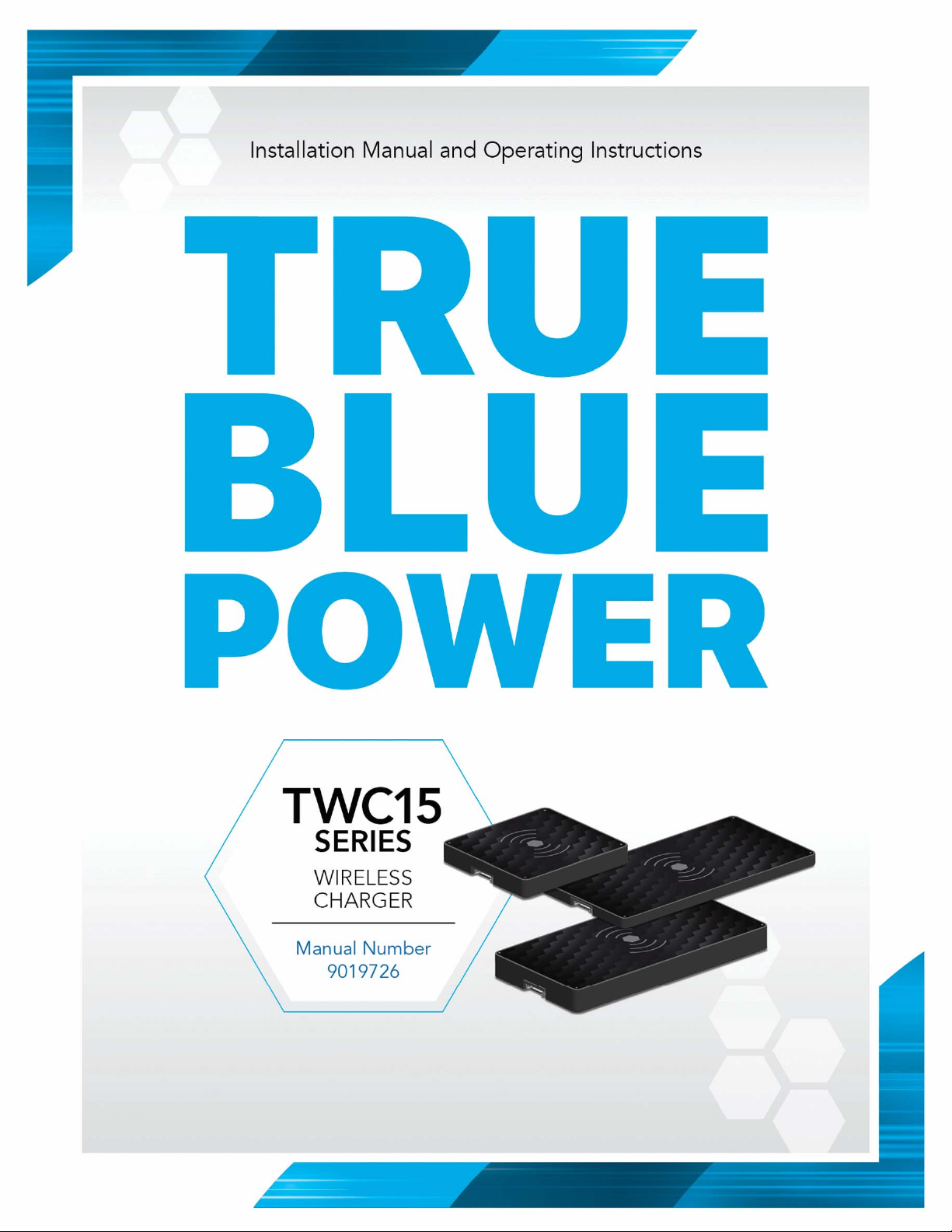
Revision A • February 15, 2022
Page 2
FOREWORD
This manual provides information intended for use by persons who, in accordance with current
regulatory requirements, are qualified to install this equipment. If further information is required,
please contact:
True Blue Power
c/o Mid-Continent Instrument Co., Inc.
Attn: Customer Service Dept.
9400 E. 34th St. N.
Wichita, KS 67226 USA
Phone 316-630-0101
Fax 316-630-0723
www.truebluepowerusa.com
www.mcico.com
We welcome your comments concerning this manual. Although every effort has been made to
keep it free of errors, some may occur. When reporting a specific problem, please describe it
briefly and include the manual part number, the paragraph/figure/table number and the page
number. Send your comments to:
True Blue Power
c/o Mid-Continent Instrument Co., Inc.
Attn: Technical Publications
9400 E. 34
Wichita, KS 67226 USA
Phone 316-630-0101
Fax 316-630-0723
© Copyright 2022
Mid-Continent Instrument Co., Inc.
th
St. N.
Download the current
version of this
installation manual
using your smartphone
or tablet.
1 Manual Number 9019726 • Revision A, February 15, 2022
Page 3
TABLE OF CONTENTS
SECTION 1 GENERAL DESCRIPTION 4
INTRODUCTION 4
PHYSICAL ATTRIBUTES 4
TECHNICAL SPECIFICATIONS 6
SECTION 2 PRE-INSTALLATION CONSIDERATIONS 7
COOLING 7
EQUIPMENT LOCATION 7
ROUTING OF CABLES 7
LIMITATIONS 7
MODIFICATIONS 8
SECTION 3 INSTALLATION 9
GENERAL INFORMATION 9
UNPACKING AND INSPECTING EQUIPMENT 9
PARTS 9
CABLE HARNESS 9
INSTALLATION 11
SECTION 4 OPERATION 14
UNIT ARCHITECTURE 14
PROTECTIVE FEATURES 14
OPERATIONAL MODES AND ALARM CONDITIONS 15
CHARGER OPERATION 15
SECTION 5 CONFORMANCE 17
INSTRUCTIONS FOR CONTINUED AIRWORTHINESS 17
ENVIRONMENTAL QUALIFICATON STATEMENT 17
2 Manual Number 9019726 • Revision A, February 15, 2022
Page 4
A
REVISION HISTORY
Rev Date Detail Approved
02/15/2022 Initial release. WVC
3 Manual Number 9019726 • Revision A, February 15, 2022
Page 5
SECTION 1 GENERAL DESCRIPTION
INTRODUCTION
The TWC15 Series, part numbers 6430015-( ) are Qi Compatible High Power Wireless Chargers.
The units are certified accessories that convert 12 to 32 volts of DC electrical input from the aircraft
to a maximum of 15 Watts of wireless charging for personal electronic devices (PEDs), such as
phones, tablets, etc. The TWC15 wireless chargers can be mounted in a variety of locations and
orientations throughout the aircraft. Three different units provide aircraft owners with flexibility to
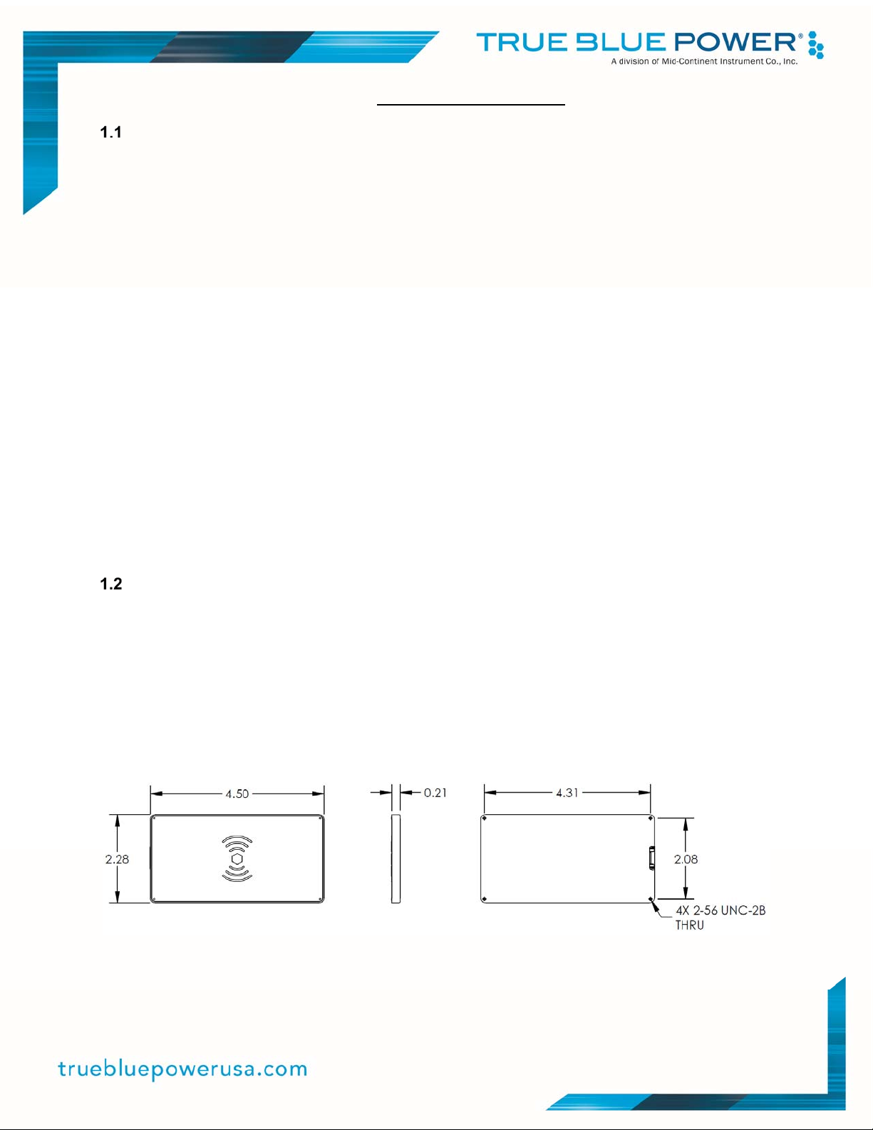
select the best wireless charger suitable for installation. The 6430015-1 (referred to as -1) is very
thin (0.21”) and can be located where a low profile product is required to fit into locations such as
beverage trays. The 6430015-2 (-2) has the smallest footprint (2.28” x 2.45”) and can fit in those
locations where mounting area is very small. For installations where a larger charging area is
desired, the 6430015-3 (-3) has 3 coils that provide a larger ‘sweet-spot’ for locating your device to
be charged. All three units are certified to FAA TSO-C71 and qualified to multiple RTCA DO-160G
requirements, providing confidence for installation in the cockpit or cabin. The TWC15 Series of
wireless chargers have built-in protections for short circuit, over-load, over temperature, power
surge and foreign object detection (FOD). They are designed to protect against reverse polarity
installation and have temperature monitoring and shutdown capability, allowing the unit to handle
unforeseen conditions safely.
Small, compact and powerful, with plenty of installation flexibility, the TWC15 Wireless Chargers
are an ideal choice as a highly useful and effective addition to any aircraft.
PHYSICAL ATTRIBUTES
The TWC15 wireless charger family provides three different configurations, each an integrated
component contained in a metal enclosure that can be mounted in many different aircraft locations
with a variety of mounting options/alternatives. All units utilize the same external connection that
provides for power input and return, a line for enabling the charger and lastly a dedicated line for
providing operating status of the wireless charger. Each wireless charger features four (4)
threaded holes designed for attachment with 2-56 screws. Refer to Figures 1.1, 1.2 and 1.3 for
specific unit dimensions.
Figure 1.1
6430015-1 Drawing
4 Manual Number 9019726 • Revision A, February 15, 2022
Page 6
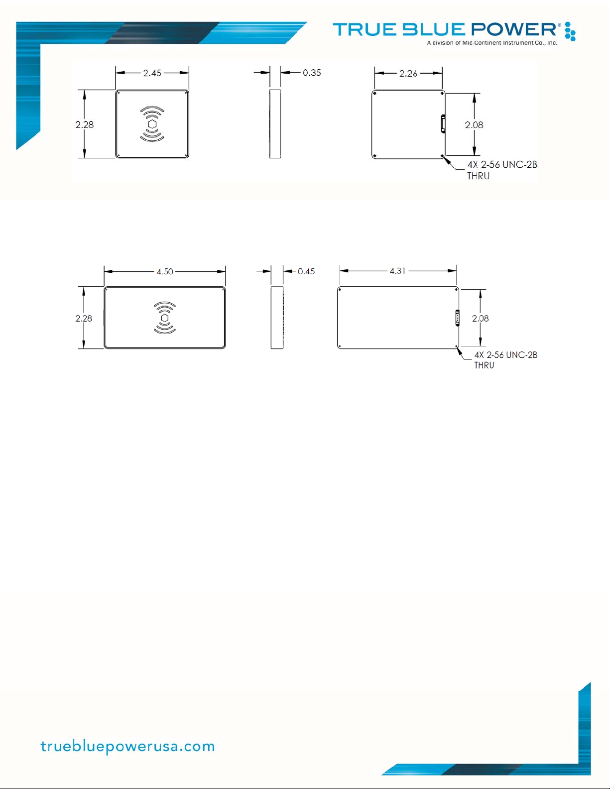
Figure 1.2
6430015-2 Drawing
Figure 1.3
6430015-3 Drawing
5 Manual Number 9019726 • Revision A, February 15, 2022
Page 7
r
–
A
TECHNICAL SPECIFICATIONS
TWC15 Models and Type
Part Number:
6430015-1
6430015-2
6430015-3
Description:
Thin wireless charger – 1 coil
Compact wireless charger – 1 coil
Triple coil wireless charge
Table 1.1
3 coils
Electrical Attributes
Input Voltage 12-32 VDC
Input Power 26 watts max; 2.2 amps @ 14 VDC / 0.9 amps @ 28 VDC
Output Power 15 watts maximum
Table 1.2
Physical Attributes
Weight:
-1:
-2:
-3:
Dimensions
-1:
-2:
-3:
3.4 oz. (96 g)
3.0 oz. (85 g)
5.9 oz. (167 g)
4.50 inches wide X 2.28 inches deep X 0.21 inches high
(114.3 mm wide x 57.9 mm deep x 5.3 mm high)
2.45 inches wide X 2.28 inches deep X 0.35 inches high
(62.2 mm wide x 57.9 mm deep x 8.9 mm high)
4.50 inches wide X 2.28 inches deep X 0.45 inches high
(114.3 mm wide x 57.9 mm deep x 11.4 mm high)
Charging Port Type Qi Compatible Wireless Charging
Maximum Device Height
3/8” (0.375”) / 9.5 mm
bove Charging Port
Connector Kit MCIA P/N 9019739-1
Mounting Under mount, flush mount
Table 1.3
Qualifications
Certification FAA TSO-C71
Environmental Qualification RTCA DO-160G Environmental Category
See Section 5.2
Table 1.4
Wireless Power Consortium (WPC) Standard
-1/-2:
-3:
Compliant to WPC 1.2.2 Standard
Compliant to WPC 1.2.4 Standard
Table 1.5
6 Manual Number 9019726 • Revision A, February 15, 2022
Page 8
SECTION 2 PRE-INSTALLATION CONSIDERATIONS
COOLING
No external cooling is required. The unit will become warm when in use. This is normal and within
operational parameters. No special mounting considerations are required; however, mounting to a
metal surface can help dissipate any heat generated and extend the life of the product.
EQUIPMENT LOCATION
The TWC15 wireless chargers are designed for mounting flexibility, allowing for installation in the
cockpit or in the cabin. They are designed for mounting typically directly underneath a panel that
will generally be in a horizontal orientation so that devices to be charged (phones, tablets, etc.) will
not move during steady flights. Clearance should be provided for the mating connector which may
require an additional inch beyond the rear of the unit.
ROUTING OF CABLES
Avoid sharp bends in cabling and routing near aircraft control cables. Avoid close proximity and
contact with aircraft structures, avionics equipment or other obstructions that could chafe wires
during flight and cause undesirable effects.
LIMITATIONS
Environmental qualifications were verified per RTCA DO-160, Revision G in lieu of those identified
within the minimum performance standards (MPS) of the TSO. The TWC15 wireless chargers
meet the DC power input requirements of TSO-C71; however, there is no direct output of DC
power as that function is replaced by wireless charging.
The conditions and tests for TSO approval of this article are minimum performance standards.
Those installing this article, on or in a specific type or class of aircraft, must determine that the
aircraft installation conditions are within the TSO standards, specification of the article and
deviations as listed above. TSO articles must have separate approval for installation in an aircraft.
The article may be installed only according to 14 CFR part 43 or the applicable airworthiness
requirements.
The wireless chargers are exciting new interfaces for charging electronic devices. The TWC15
products have been tested with and supports a wide variety of devices now emerging in the open
market. However, compatibility with all devices may not be guaranteed. True Blue Power continues
to be proactive in evaluating new devices and strives to continually improve the product as needed
to serve the vast majority of Qi Compatible personal electronic devices (PEDs).
7 Manual Number 9019726 • Revision A, February 15, 2022
Page 9
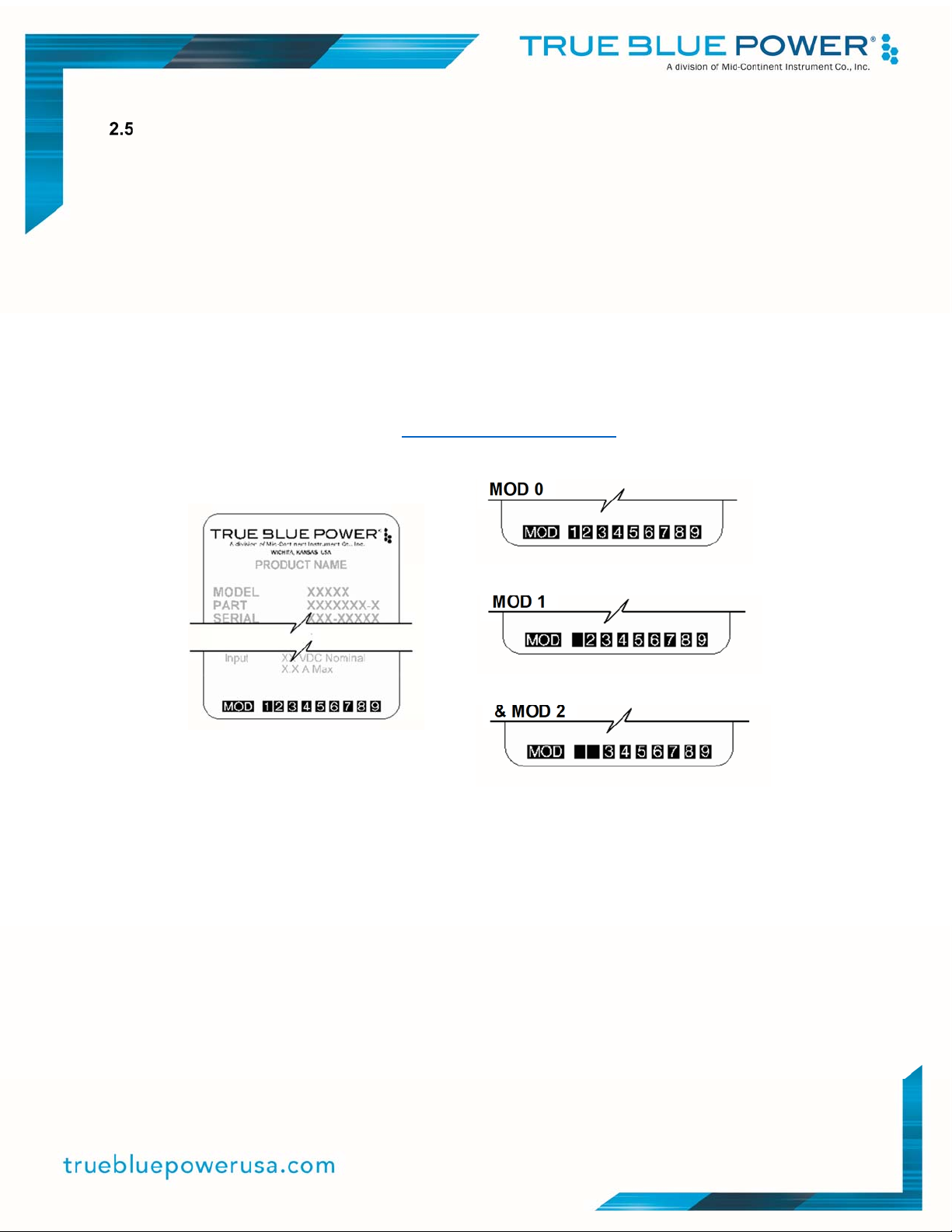
MODIFICATIONS
This product has a nameplate that identifies the manufacturer, part number, description,
certification(s) and technical specifications of the unit. It also includes the “MOD” or modification
number representing notable changes in the hardware design of the unit.
Modification (MOD) 0 is the initial release of the product and is identified on the nameplate by the
lack of marking on the MOD numbers 1 through 9 (i.e. 1-9 are visible). All subsequent
modifications are identified on the nameplate by the marking/blacking out of that particular MOD
number (i.e. for MOD 1, the number 1 is not visible and 2-9 are visible - see Figure 2.2.1 for
examples). MODs do not have to be sequentially inclusive and may be applied independent of
each other.
For additional details regarding specific changes associated with each MOD status refer to the
product published Service Bulletins at www.truebluepowerusa.com.
MOD 0
MOD 1
MOD 1
& MOD 2
Figure 2.2.1
Nameplate and MOD Status Example
8 Manual Number 9019726 • Revision A, February 15, 2022
Page 10
SECTION 3 INSTALLATION
GENERAL INFORMATION
This section contains interconnect diagrams, mounting dimensions and other information
pertaining to the installation of the TWC15 family of Qi Compatible Wireless Chargers. After
installation of cabling and before installation of the equipment, ensure that power and ground are
applied to the proper pins specified in Section 3.3.2, Pin Assignment Information.
UNPACKING AND INSPECTING EQUIPMENT
When unpacking this equipment, make a visual inspection for evidence of any damage that may
have occurred during shipment.
PARTS
3.3.1 Included Parts
A. Qi Compatible Wireless Charging Port MCIA P/N 6430015-( )
B. Installation Manual MCIA P/N 9019726
C. Connector Kit MCIA P/N 9019739-1
Mating Connector, 4-pin
Pins (6) (4 required, 2 spares)
Screws, #2-56 x 1/4 flat-head (4)
Screws, #2-56 x 3/16 pan-head (4)
3.3.2 Installer Supplied Parts
A. Cable Harness Wire See Section 3.4.1 for specifications
B. Circuit Breaker Recommendation 3 amp (2 amp may be sufficient for 28V aircraft)
CABLE HARNESS
Construct the cable harness following the instructions outlined below and per Figure 3.1.
Refer to Section 2: Pre-Installation Considerations, for routing precautions.
3.4.1 Wire Gauge Selection
Use of PTFE, ETFE, TFE, Teflon or Tefzel insulated wire is recommended for aircraft use.
The wire harness should utilize 20-24 AWG stranded wire. Refer to table 3.1 below. This table is
provided to aid in the consideration of voltage drop due to harness length. Any other wiring
standards that are applicable to the installation should also be considered.
Wire Gauge Wire Length
20 AWG stranded wire 24 ft
22 AWG stranded wire 14 ft
24 AWG stranded wire 9 ft
Table 3.1
Wire Gauge and Length
9 Manual Number 9019726 • Revision A, February 15, 2022
Page 11
3.4.2 Pin Assignment Information and Location
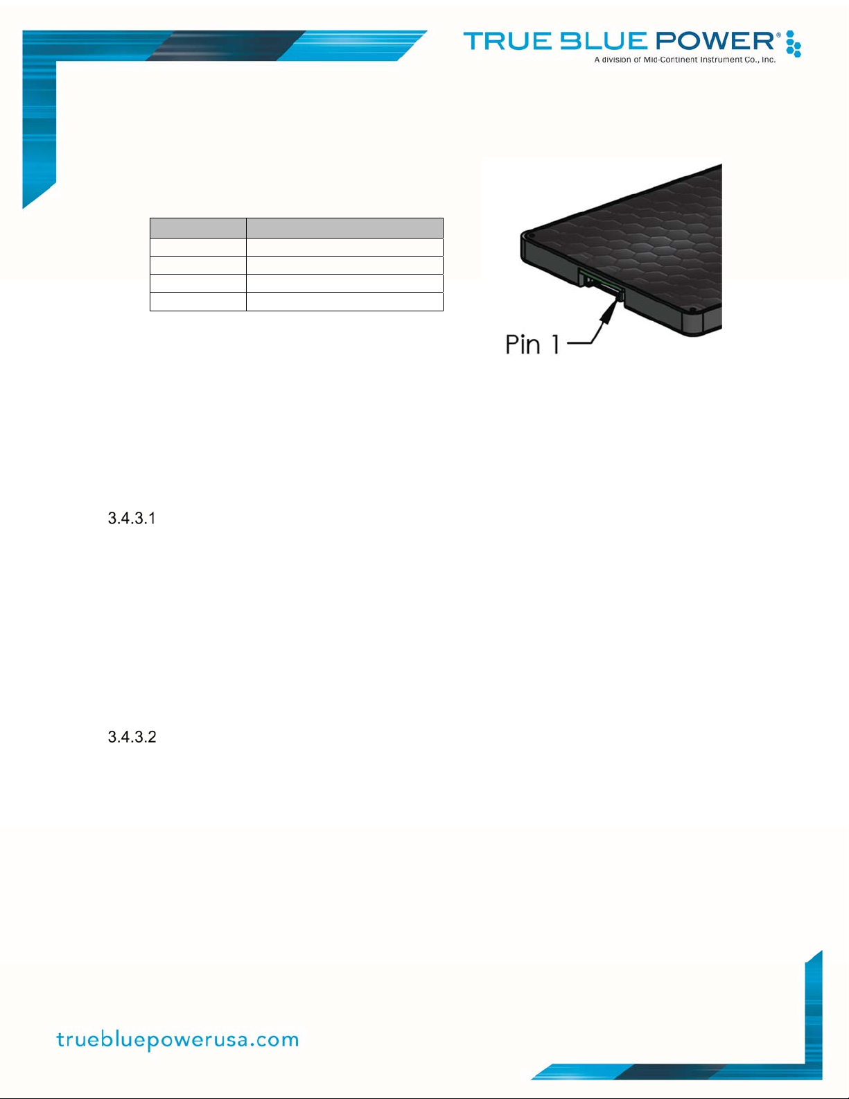
See Table 3.2 for pinout definition and Figure 3.1 for pin locations.
Pin Number
1 Aircraft Power (12-32 VDC)
2 Ground
3 Status
4 Enable
Signal
Table 3.2
Wireless Charger Pin Assignment
Figure 3.1
Wireless Charger Pin Locations
Note: Pins should be crimped using Molex Hand Crimp Tool 213309-1000. See the Molex Hand
Crimp Tool User Manual for crimp procedures.
3.4.3 Wiring Connections
Enable Pin
The TWC15 enable pin will automatically turn on the wireless charger power supply if it is floating
or not connected to power (12-32 VDC). If the wireless charger is to be enabled whenever power
is provided, the enable pin does not need to be connected. However, if the aircraft installation
includes the capability to enable/disable the wireless charger, the enable pin can be wired
accordingly; if the enable pin is open it will enable input power; if connected to aircraft power (1232 VDC) it will disable input power. Controlling the enable can be performed through an external
100K Ω series resistor if desired. If controlling the enable is performed from external electronics
operating at 5V, the external series resistor should be 2.2K Ω or less.
Status Indication
The status output is designed to drive an external LED with minimum additional components. A
LED connected between this output and 28V will light with 32 mA of current. For lower LED
current (less brightness) add an external resistor in series with your LED. The status can survive a
continuous short to 28V.
For a more complex flight monitoring systems, the status line is an open-drain output switching to
ground with a 1 Watt 866 Ω resistor. If interfacing to 5 volt electronics, a 10K Ω resistor pull-up to
an external 5V will provide levels between 5V (Status is Off) and 0.4V (Status is on) to interface to
other circuits.
10 Manual Number 9019726 • Revision A, February 15, 2022
Page 12
3.4.4 Harness Verification
Note:
The TWS15 High Power Wireless Chargers have built-in reverse polarity protection for the power
connector. If Pins 1 and 2 are swapped, the unit will not be damaged, but will also not function.
Once the cable harness is prepared, prior to connecting the TWC15, activate the aircraft power
bus and use a multimeter to verify that aircraft power and ground are supplied with appropriate
voltage on the proper pins within the mating harness.
INSTALLATION
The TWC15 can be installed in many different ways and locations, noting that in order for the TWC15
to charge wireless devices, the panel thickness + device (phone, tablet, etc.) case combined
thickness should not exceed 0.375”. Below are typical mounting methods:
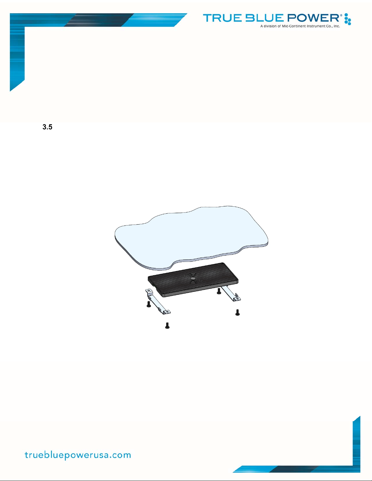
Undermount panel concepts with brackets attaching to the aircraft panel per Figures 3.2 and 3.3.
Undermount panel with screws attaching directly to charger per Figure 3.4.
Flush mount with screws attaching bottom of charger to recessed panel per Figure 3.7.
Many other options are available for mounting the TWC15 wireless chargers depending on your
aircraft’s available mounting locations and orientations.
Figure 3.2 Undermount Through Hole Bracket Concept
(-1 Configuration Shown)
11 Manual Number 9019726 • Revision A, February 15, 2022
Page 13
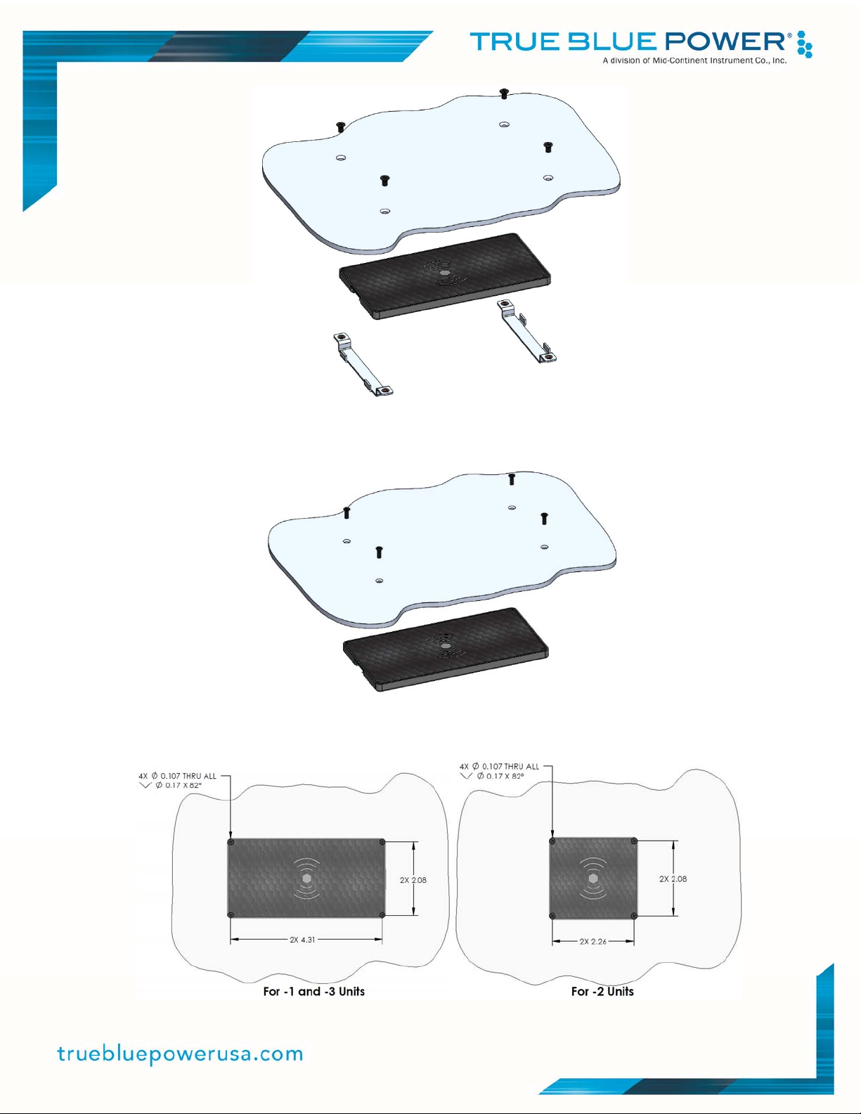
Figure 3.3 Undermount With Threaded Bracket Concept
(-1 Configuration Shown)
Figure 3.4 Undermount Direct to Charger
(-1 Configuration Shown)
Figure 3.5
Undermount Direct Mounting to TWC15 Dimensions
12 Manual Number 9019726 • Revision A, February 15, 2022
Page 14
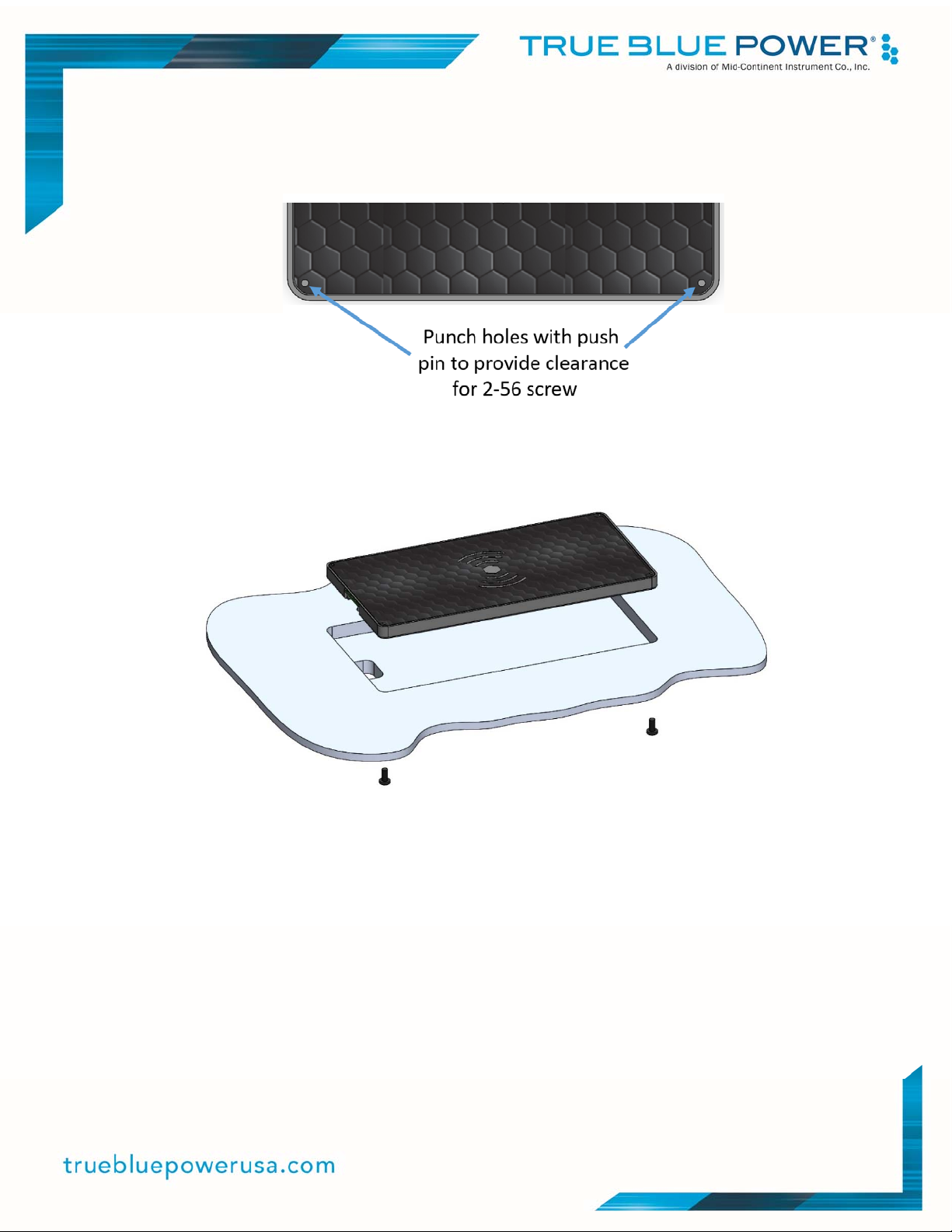
Mounting TWC15 units below the panel using a direct mount to the wireless charger requires
countersinking holes (see Figure 3.5 above) for a #2 screw. Additionally, the label on top of the
wireless charger has 4 small gray dots in each corner. A push pin can be used to punch
through the label to allow the 2-56 screws (qty 4) to attach from above per Figure 3.6.
Figure 3.6
Threaded Hole Locations for 2-56 Threaded Holes
Figure 3.7 Flush Mount
(-1 Configuration Shown)
Mounting TWC15 units flush (from above) requires providing a recess height equivalent to the
height of the charger. Cutouts need to be made in the panel to allow for connection of the 4pin connector; 4 drilled holes are also required to provide attachment from below with 2-56
screws.
13 Manual Number 9019726 • Revision A, February 15, 2022
Page 15
SECTION 4 OPERATION
UNIT ARCHITECTURE
The TWC15 Series Wireless Chargers convert an aircraft (DC) input voltage (from 12 to 32 volts)
to a wireless charger that can charge personal electronic devices compatible with the Qi wireless
specification.
The unit is designed as a DC-to-DC converter output regulated to meet the Qi standard that
regulates wireless charging up to 15 watts. The TWC15 units provide several protections to
assure continued safe operation of your aircraft.
PROTECTIVE FEATURES
4.2.1 Short Circuit Protection
The TWC15 units are capable of surviving a short circuit event without permanent damage. The
unit goes into an over-current condition so that the average current is significantly reduced and the
device is protected.
4.2.2 Power Surge
The TWC15 units have transient voltage suppressor circuitry included to protect the wireless
chargers.
4.2.3 Reverse Polarity
The TWC15 units have reverse polarity protection; no damage to the unit will occur if the power
and return lines are connected incorrectly.
4.2.4 Over-Load Protection
The TWC15 monitors the power draw individually on each charging coil. If the requested power
from the personal electronic device is too high, the charger will indicate a FAULT on the status line.
4.2.5 Low Input voltage Shutdown
If the input voltage applied to the TWC15 drops below 12 VDC the unit will shut down until the
applied voltage returns to an operational level within range.
4.2.6 Over-Temperature
When the internal temperature of the TWC15 exceeds designed thresholds, the unit will shut down
and stop providing power.
4.2.7 Foreign Object Detect (FOD)
If foreign objects (items like coins, paper clips, etc.) are placed above the wireless coil charging
surface (with or without a personal electronic device present), it will indicate a FAULT on the status
line.
14 Manual Number 9019726 • Revision A, February 15, 2022
Page 16
OPERATIONAL MODES AND ALARM CONDITIONS
The TWC15 High Power Wireless Chargers provide external status via connector pin #3. Table
4.1 provides indications for all operational modes and alarm conditions.
Operational Mode Status Indication
-1/-2 Units
Standby
Charging
ChargeComplete
ShortCircuit
PowerSurge
LowInputVoltageShutdown
Over‐Temperature
Alarm:Over‐LoadProtection
Alarm:ForeignObjectDetect
1000mson,500msoff 1000mson,500msoff
Off/NoIndication
Off/NoIndication
Off/NoIndication
Off/NoIndication
Off/NoIndication
Table 4.1
Status Indications
On
On
On
Status Indication
-3 Units
On
500mson,500msoff
Off/NoIndication
Off/NoIndication
Off/NoIndication
Off/NoIndication
200mson,200msoff
200mson,200msoff
CHARGER OPERATION
Be sure to adhere to the following precautions when charging your Personal Electronic Device
(PED):
A. Do not use a case with a magnetic or iron plate.
B. Do not use a case with a pop socket.
C. Do not use a device with a thick (> 3/16”) protective case.
D. Do not place any foreign objects between your device and the wireless charger’s
surface, including metal pads, credit cards, keys, coins or metal.
E. The protective phone case (thickness) and the position of your device on the wireless
charger will affect the charging speed. The farther it is placed above and from the
center of the wireless charger, the slower the charging speed will be.
Connecting to the TWC15 wireless chargers is relatively straightforward. Be sure to place your
PED above the wireless charger, making note of the optimal location for that charger. The -3 unit
(triple coil) has a much larger area for PED charging. See Figures 4.1, 4.2 and 4.3.
15 Manual Number 9019726 • Revision A, February 15, 2022
Page 17
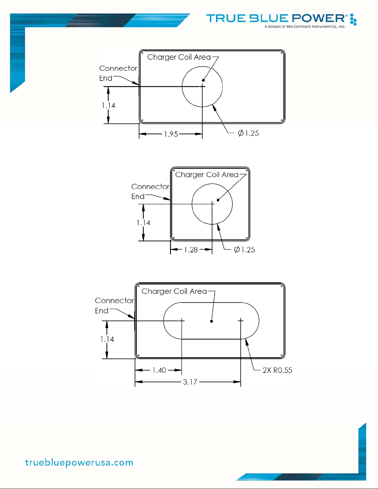
Figure 4.1
Charging Optimal Area (-1)
Figure 4.2
Charging Optimal Area (-2)
Figure 4.3
Charging Optimal Area (-3)
16 Manual Number 9019726 • Revision A, February 15, 2022
Page 18
gory
)
SECTION 5 CONFORMANCE
INSTRUCTIONS FOR CONTINUED AIRWORTHINESS
No periodic scheduled maintenance or calibration is necessary for continued airworthiness of the
TWC15 series Wireless Chargers. If the unit fails to perform to specifications, the unit must be
removed and serviced by Mid-Continent Instruments and Avionics or their authorized designee.
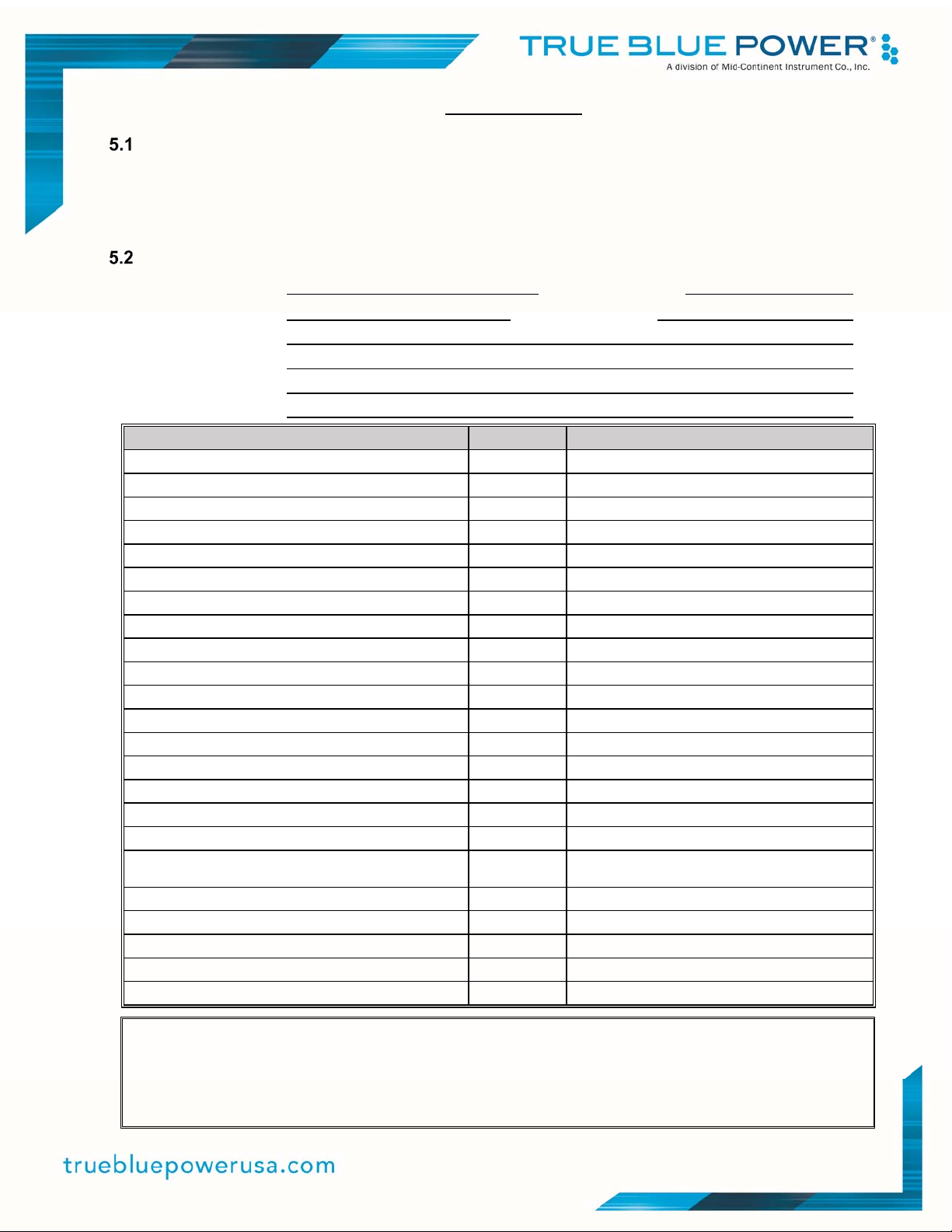
ENVIRONMENTAL QUALIFICATON STATEMENT
MODEL NUMBER: TWC15 Series PART NUMBER: 6430015-( )
DESCRIPTION: Wireless Charger CERTIFICATION: FAA TSO-C71
MANUFACTURER: True Blue Power, a division of Mid-Continent Instrument Co., Inc.
ADDRESS: 9400 E. 34th St. North, Wichita, KS 67226, USA.
SPECIFICATION: Test Specification (TS) 809 Test Data Sheet (TDS) 809
STANDARD: RTCA DO-160, Rev G, dated 12/08/10
CONDITIONS SECTION DESCRIPTION OF TEST
Temperature and Altitude 4
Temperature Variation 5
Humidity 6
Operational Shock and Crash Safety 7
Vibration 8
Explosion 9
Waterproofness 10
Fluids 11
Sand and Dust 12
Fungus 13
Salt Spray 14
Magnetic Effect 15
Power Input 16
Voltage Spike 17
Audio Frequency Conducted Susceptibility 18
Induced Signal Susceptibility 19
Radio Frequency Susceptibility 20
Category R; Curves C, C1
Category C4
Category S2
Category B
Category B
Category X
Category X
Category X
Category X
Category X
Category X
Category Z
Category B(XX)
Category B
Category R
Category X
Category X
Emission of Radio Frequency Energy 21 Category ML (-1)
Lightning Induced Transient Susceptibility 22
Lightning Direct Effects 23
Icing 24
ESD 25
Fire, Flammability 26
REMARKS:
Section 4: Category C4 with excursions as declared by the manufacturer:
4.6.1: Altitude adjusted from 35k to 55k feet.
Section 7: Category B with excursions as declared by the manufacturer:
7.2.1: Operational Shock adjusted from 11ms, 6g to 11ms, 15g
7.3.1: Crash Safety Impulse adjusted from 11ms, 20g to 11ms, 30g
7.3.3: Crash Safety Sustained adjusted from 20g to 30g
Cate
Category X
Category X
Category X
Category A
Category X
BL (-2, -3
17 Manual Number 9019726 • Revision A, February 15, 2022
 Loading...