


Revision Q • Oct 6, 2020
FOREWORD
This manual provides information intended for use by persons who, in accordance with current
regulatory requirements, are qualified to install this equipment. If further information is required, please
contact:
True Blue Power
c/o Mid-Continent Instrument Co., Inc.
Attn: Customer Service Dept.
9400 E. 34th St. N.
Wichita, KS 67226 USA
Phone 316-630-0101
Fax 316-630-0723
www.truebluepowerusa.com
www.mcico.com
We welcome your comments concerning this manual. Although every effort has been made to keep it
free of errors, some may occur. When reporting a specific problem, please describe it briefly and
include the manual part number, the paragraph/figure/table number and the page number. Send your
comments to:
True Blue Power
c/o Mid-Continent Instrument Co., Inc.
Attn: Technical Publications
9400 E. 34
Wichita, KS 67226 USA
Phone 316-630-0101
Fax 316-630-0723
© Copyright 2015
Mid-Continent Instrument Co., Inc.
th
St. N.
Download the current
version of this
installation manual
using your smartphone
or tablet.
1 Manual Number 9016798 • Revision Q, October 6, 2020

TABLE OF CONTENTS
SECTION 1 GENERAL DESCRIPTION 4
1.1 PURPOSE 4
1.2 PHYSICAL
1.3 FUNCTIONAL
1.4 TECHNICAL
SECTION 2 PRE-INSTALLATION CONSIDERATIONS 6
2.1 COOLING 6
2.2 EQUIPMENT
2.3 ROUTING
2.4 LIMITATIONS 7
2.5 MODIFICATIONS 7
DESCRIPTION 4
DESCRIPTION 4
SPECIFICATIONS 5
LOCATION 6
OF CABLES 6
SECTION 3 INSTALLATION 11
3.1 GENERAL 11
3.2 PRE-INSTALLATION
INSPECTION 11
3.3 PARTS 11
3.4 INSTALLATION 12
SECTION 4 OPERATION 21
4.1 DESCRIPTION 21
4.2 THEORY
4.3 INSTALLED
OF OPERATION 21
OPERATION 24
4.4 MAINTENANCE 25
4.5 PERFORMANCE 27
SECTION 5 CONFORMANCE 30
5.1 TEST AND VERIFICATION INTERVALS 30
5.2 COMPONENT
5.3 STORAGE
MAINTENANCE MANUAL 30
INFORMATION 30
5.4 DISPOSAL 31
5.5 ENVIORNMENTAL
QUALIFICAION STATEMENT 32
2 Manual Number 9016798 • Revision Q, October 6, 2020

REVISION HISTORY
Rev Date Detail Approved
1 04/30/2009 Preliminary release. BAW
2 12/02/2009 Updated information. BAW
A 03/11/2010 Production release. BAW
B 04/15/2010 Revised Figure 3.3 Installation Diagram. BAW
Added MCI P/N 54-2007-1 to diode options in
C 05/18/2010
Section 3.3.2. Add Section 4.3.5 and related
information regarding MD835-2 version.
D 10/12/2010 Update unit picture with True Blue Power label. MKN
E 01/13/2011 Updated to include optional annunciator switch. JDS
F 04/14/2011 Added 9017201 5V Module as an optional part. BAW
G 07/27/2011
Added additional installation instructions for
9017201 5V Module.
Update manual to add references to True Blue
Power division of Mid-Continent Instrument Co.,
Inc. Identify new model number “TS835-( )” while
H 07/06/2012
maintaining unit part number references as
“MD835-( )”. Added information associated with
new -5 version and Mod 1 improvements. Updated
certification from FAA TSO C179 to C179a.
Add ETSO to Table 1.2. Updated Section 2.2 and
J 11/15/2012
2.4 for equipment location limitations. Removed
4.2.6. Updated 4.2.7. Add 4.2.8 regarding
software/complex hardware.
K 01/6/2014
L 02/26/2015
Updated document for vented version that applies
to all 835 units.
Add Mod 3: Extended filtering for high-transient
load current.
Change Environmental Qualification table: For
M 12/06/2016
CONDITION “Lightning Induced Transient
Susceptibility” change DESCRIPTION OF TEST to
A3H3L3.
Update 3.2 and 5.3 with information regarding state
N 11/22/2017
of charge for shipping and recharge intervals for
storage. Added cold test clarification. Minor format
and reference updates.
P 05/14/2020
Q 10/06/2020
Update style and brand to meet Marketing and
Engineering guidelines.
Updated section 5.5 Radio Frequency
Susceptibility.
BAW
MKN
BAW
BAW
JDS
CAS
KW
BAW
DLR
VAA
3 Manual Number 9016798 • Revision Q, October 6, 2020

SECTION 1 GENERAL DESCRIPTION
1.1 PURPOSE
The TS835 series Emergency Power Supply (EPS) is designed to supply DC power to the aircraft
emergency bus when the main power bus has been de-energized. This emergency power can be
utilized to maintain operation of required equipment in the event of a primary system power loss.
During normal aircraft operation, the TS835 EPS will utilize the aircraft’s primary power bus to
recharge or maintain existing charge at full capacity.
1.2 PHYSICAL DESCRIPTION
The TS835 EPS consists of a single chassis with a 13-pin ARINC-style connector for electrical
interface. Units with modification (MOD) 2 include a factory replaceable fuse that limits the output
current of the EPS. The unit is designed to be mounted in a ¼-ATR aircraft equipment rack. The end
plate of the unit also provides an alignment hole that mates with the mounting rack. A handle on the
front of the unit allows ease of removal and a convenient carrying method. There is an adjustment on
the front of the unit for setting the variable 3.0-5.5VDC output for the -5 version of the product.
1.3 FUNCTIONAL DESCRIPTION
During typical operation, the TS835 utilizes input power from the primary aircraft power supply to
charge and/or maintain the charge on the internal battery cells. In the event of primary aircraft power
loss, the TS835 will automatically supply power to the associated external loads without interruption.
4 Manual Number 9016798 • Revision Q, October 6, 2020

1.4 TECHNICAL SPECIFICATIONS
Electrical Attributes
Power Input 20 to 32 VDC, 5.2A max
20A max total
Power Output
Primary: 24.5 VDC nominal; Auxiliary: 3.0-5.5VDC
adjustable (5A max)
Battery Capacity 4.5 Ah nominal @ 1C rate
Maintenance Perform capacity check every 2 years
Reliability 10 year expected life (80% initial capacity retained)
Table 1.1
Physical Attributes
Weight 4.8 pounds (2.16 kg)
Dimensions
(see Figure 2.2)
12.7 inches long max. (+1 inch for handle)
3.1 inches high max. (excluding rear tab)
2.3 inches wide max.
Mating Connector ITT Cannon DPXB-13-33S-0001 or equivalent
Mounting 1/4 ATR Rack
Table 1.2
Qualifications
Certification
Performance Qualification
FAA TSO-C179a
EASA TSO (ETSO) C179a
RTCA DO-311 Minimum Operational Performance
Standards for Rechargeable Lithium Battery Systems
RTCA DO-160G See Section 5.5
Environmental Qualification
With MD835 5V Module (P/N 9017201) installed: DO160E, Section 20 (HG); DO-160F, Section 22 [A4G44]
Table 1.3
5 Manual Number 9016798 • Revision Q, October 6, 2020

SECTION 2 PRE-INSTALLATION CONSIDERATIONS
2.1 COOLING
No internal or external cooling of the unit is required. The unit is designed to operate over a wide
temperature range and is designed with internal thermal monitoring and protection circuits. See
Section 4: Operation for more details.
2.2 EQUIPMENT LOCATION
The TS835 EPS is designed for mounting flexibility, allowing for installation with no requirement for
temperature or pressure control. Although not required, optimum performance and life can be
achieved by mounting the TS835 in a temperature controlled section of the aircraft. In addition to
altitude and temperature tolerance, the unit is also designed to withstand high levels of condensing
humidity. However, installation locations where the unit could be subject to standing or direct water
exposure should be avoided. Tested and certified mounting includes the use of a standard ¼-ATR
avionics mounting rack. Access to the rear connector may be needed for installation but the nature of
the rack allows for convenient removal and installation of the unit from the front.
Failure mode, effects, and criticality analysis of the TS835 has shown that the potential for the release
of toxic or flammable gases as a result of over charge and over discharge conditions is extremely
improbable. However, if the unit does not have the add-on vent kit and exhaust hose, the unit should
be installed in a well-ventilated (positive flow) compartment for additional risk mitigation. The unit shall
not be installed in compartments where lines, tanks or equipment containing fuel, oil or other
flammable fluids are present; nor shall it be installed adjacent to engine firewalls or sources of ignition.
2.3 ROUTING OF CABLES
The wires and cable bundle associated with the unit are heavy gauge wire and carry significant power.
Be aware of routing cables near other electronics or with other wire bundles that may be susceptible to
high energy flow.
Avoid sharp bends in cabling and exhaust hose. Avoid routing near aircraft control cables. Also avoid
proximity and contact with aircraft structures, avionics equipment, or other obstructions that could
chafe wires and hoses during flight, and cause undesirable effects. The interconnect cables and
exhaust hose should not run adjacent to heaters, engine exhausts, or other heat sources.
6 Manual Number 9016798 • Revision Q, October 6, 2020
2.4 LIMITATIONS
The conditions and tests for TSO approval of this article are minimum performance standards. Those
installing this article, on or in a specific type or class of aircraft, must determine that the aircraft
installation conditions are within the TSO standards. TSO articles must have separate approval for
installation in an aircraft. The article may be installed only according to 14 CFR part 43 or the
applicable airworthiness requirements.
See Section 4.5 for Performance Specifications and potential limitations and ratings under various
environmental and application installations. Also see Section 2.2 for limitations associated with
equipment installation location.
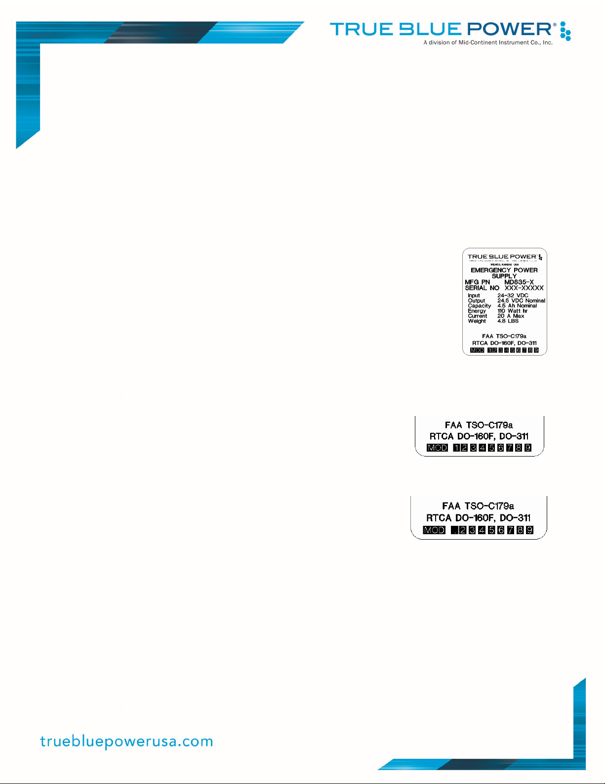
2.5 MODIFICATIONS
Each model TS835 (part number MD835-( )) has a nameplate that identifies
the manufacturer, part number, description, certifications and technical
specifications of the unit. It also includes the “MOD” or modification number
representing notable changes in the revision history of the unit (See Table 2.2).
The following are descriptions of the current modification releases of the
TS835 EPS.
MOD 0
Modification (MOD) 0 is identified on the nameplate by the lack of marking on the MOD numbers 1
through 9 (i.e. 1-9 are visible).
Mod 0 is the initial release of the TS835 EPS.
MOD 1
Modification (MOD) 1 is identified on the nameplate by the marking/blacking out of MOD number 1 (i.e.
1 is not visible and 2-9 are visible).
Mod 1 of the TS835 EPS contains the following changes from MOD 0:
-Updated TSO from C179 to C179a
-The external installation of CR1 diode per Installation Wiring Diagrams is NOT required (optional)
-The 3.0 amp maintenance fast charge feature has been removed
-Standard charge rate during both operation and maintenance has been increased from 0.8 amps to
3.5 amps
-Adjustable 5 volt auxiliary power output is available for TS835-5 model
-Connector has been modified to accept multiple mating connector configurations for -1 and -5 models
7 Manual Number 9016798 • Revision Q, October 6, 2020

MOD 2
Modification (MOD) 2 is identified on the nameplate by the marking/blacking out of MOD number 2 (i.e.
1 and 2 are not visible; 3-9 are visible).
Mod 2 of the TS835 EPS contains the following changes from MOD 1:
-End plates and connecter are sealed to prevent discharge gases from escaping these locations.
-Case has a ‘vent’ hole, covered by a label, for gases to escape in the event of a catastrophic
overcharge. The label can be removed and an MCIA vent kit (p/n 9017983), and customer supplied
high temperature silicone hose, can be installed for controlled venting.
MOD 3
Modification (MOD) 3 is identified on the nameplate by the marking/blacking out of MOD number 3 (i.e.
1, 2 and 3 are not visible; 4-9 are visible).
Mod 3 of the TS835 EPS contains the following changes from MOD 2:
-Extended filtering for high-transient load current.
8 Manual Number 9016798 • Revision Q, October 6, 2020
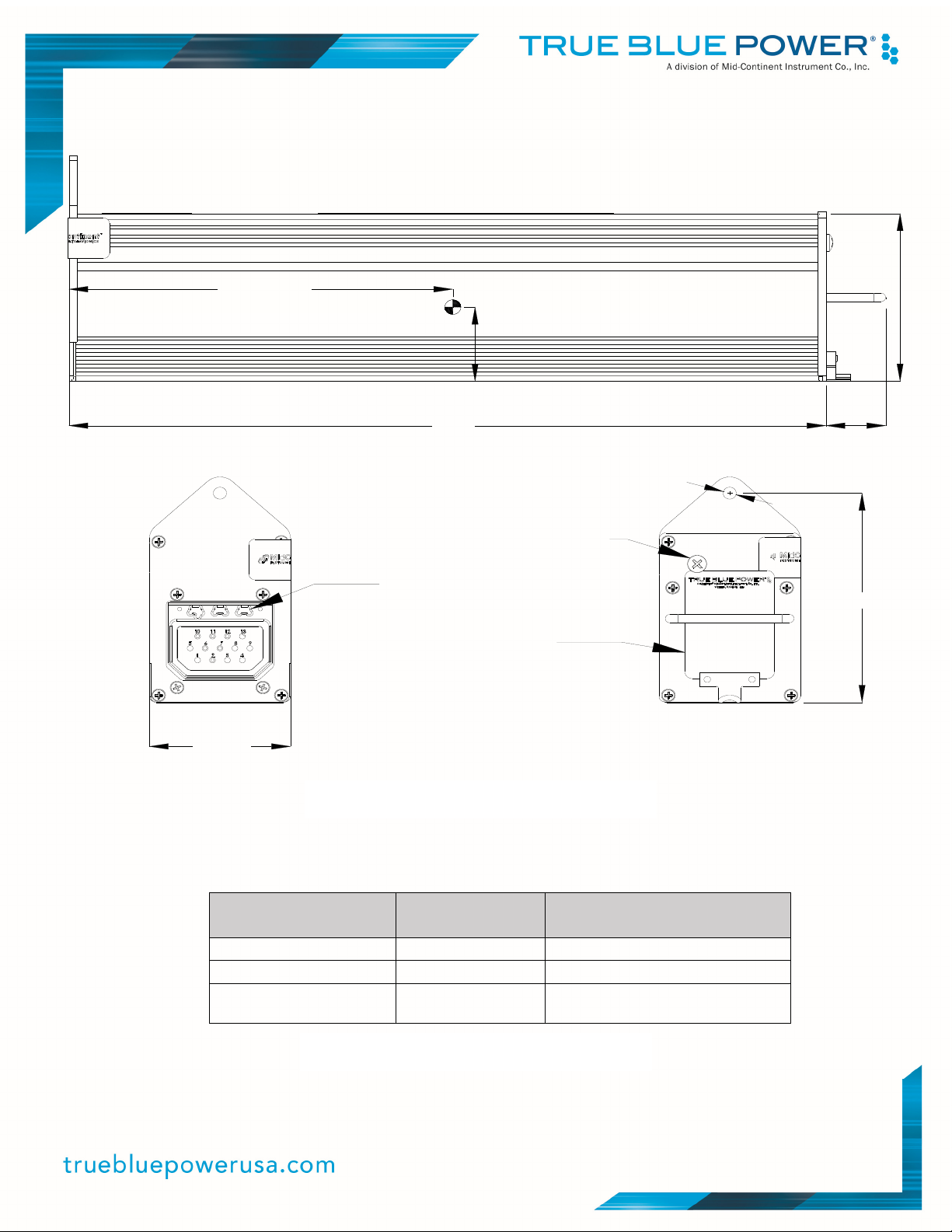
6.45 CG (ref)
1.37 CG (ref)
3.1
2.365
12.68
Ø.221 Alignment hole
Auxiliary
output
Connector
keying.
Nameplate
adjustment
(-5 only)
Figure 2.2 TS835 Outline Drawing
1.000
3.87
Model Number
Mid-Continent
Part Number
Identifying Feature
TS835-1 MD835-1 Standard model
TS835-2 MD835-2 Fuse bypass option
Additional auxiliary output (3-
TS835-5 MD835-5
Table 2.2 Model and Part Numbers
9 Manual Number 9016798 • Revision Q, October 6, 2020
5.5VDC)

Pin #
A Power input from aircraft
B Power output to emergency bus
C Power input from MD835 Pin 11
D Test (out) to MD835 Pin 2
E Test (in) to MD835 Pin 6
F Power output to MD835 pin 10
G Aircraft ground
Connector Pinout
Figure 2.3
MD835 Control Switch Annunciator Outline Drawing and Pinout
Specifications
Power Input 28 VDC 15 amps max
Lighting LEDs
Weight 0.33 lbs
Temperature -55°C to 70 °C
Altitude 0 to +55,000 Ft.
Connector MS3102E16S-1P
Mating Connector MS3106F16S-1S
Color Bezel and Case: Black
Arm, Off, Test Labels: Opaque and Backlit White
STBY Annunciator: Backlit Amber on discharge
TEST Annunciator: Backlit Green (pass); no light (fail)
Table 2.3 MD835 Annunciator Specifications
10 Manual Number 9016798 • Revision Q, October 6, 2020

SECTION 3 INSTALLATION
3.1 GENERAL
This section contains mounting, electrical connections and other information required for installation.
These instructions represent a typical installation and are not specific to any aircraft.
3.2 PRE-INSTALLATION INSPECTION
A. Unpacking: Carefully remove the TS835 EPS from the shipping container. The shipping
container and packing are designed specifically for the transit of lithium batteries and
approved by international transportation agencies. These materials should be retained for
use should these units require future shipment.
B.
C. Inspect for Damage: Inspect the shipping container and units for any signs of damage
sustained in transit. If necessary, return the units to the factory using the original shipping
container and packing materials. File any claim for damages with the carrier.
D.
E. NOTE: The unit is shipped with approximately a 30% state-of-charge (if shipped by air) or
a 50% state-of-charge (if shipped by ground) to extend storage life and prevent loss of
capacity. Perform a complete charge on the TS835 using the procedures listed in this
manual upon receipt (prior to storage and again prior to installation/use).
3.3 PARTS
Included Parts
A. MD835-( ) Emergency Power Supply
B. 20A mini blade fuse, installed (MCI p/n 9016763 or equivalent)
C. Installation Manual (MCI p/n 9016798)
D. CR1 diode kit (MCI p/n 9017207, Mod 0 units only)
Installer Supplied Parts
A. Rack: ¼ ATR (MCI p/n 5120-107-C01 or equivalent)
B. Mating Connector: 13-pin ARINC (MCI p/n 9016600-2, -4, -5 or equivalent)
C. Emergency Fuse Bypass Switch (-2 version only):
Two position (off-on, capable of appropriate current for applied load)
(Panel Controls)
D. MCI Control Switch Annunciator (MCI p/n 9017176)
E. Annunciator Mating Connector: 7-pin circular (MCI p/n 9017119 or equivalent)
- OR, alternative option -
F. Panel Switch: Three position (off-on-momentary, capable of 20A minimum)
G. Test Annunciator: 327 lamp or equivalent
11 Manual Number 9016798 • Revision Q, October 6, 2020

Optional Parts
(For Emergency Power “On” Annunciation)
(This feature is included in the MCI Control Switch Annunciator p/n 9017176)
A. Diodes: 1N5614 (qty of 2), or equivalent
B. Annunciator: 327 lamp or equivalent
(To add 5VDC Auxiliary Power Output to -1 or -2 versions)
(This feature includes CR1 diode and Mating Connector)
C. MD835 5V Module (MCI p/n 9017201)
(To attach a vent hose to the MD835 unit; this is only for units made after 1/15/14)
D. Vent kit, MCI p/n 9017983. Use with ¾” ID x 1” OD min. high temp silicone tubing.
3.4 INSTALLATION
Install the EPS in the aircraft in accordance with the aircraft manufacturer’s instructions and the
following steps:
HARNESS PREPARATION
A. If using the MD835 5V Module (MCI p/n 9017201)
i. Prepare aircraft wiring with mating connector in accordance with Installation Wiring
Diagram Figure 3.5
ii. MD835 5V Module includes the Mating Connector shown in Figure 3.2
B. If using the MD835 Control Switch Annunciator (MCI p/n 9017176)
i. Prepare aircraft wiring with mating connectors and appropriate interconnects per
Figure 3.3 and 2.3
C. If installing an MD835-( ) MOD 0
i. The CR1 Diode identified in the Installation Wiring Diagrams is REQUIRED as an
external installation component for Mod 0 units which do not use the MD835 Control
Switch Annunciator or the MD835 5V Module.
ii. Prepare aircraft wiring with mating connector in accordance with Installation Wiring
Diagram Figure 3.3
iii. See RACK PREPARATION and Figure 3.7 below for CR1 diode mounting instructions.
D. If installing an MD835-( ) MOD 1, MOD 2, or MOD 3
i. Prepare aircraft wiring with mating connector in accordance with Installation Wiring
Diagram Figure 3.3
ii. The CR1 Diode is optional for Mod 1, Mod 2 and Mod 3 units and allows the emergency
loads or bus to be powered through the main bus when the battery is removed from the
installation.
iii. The CR1 Diode is included as part of the MD835 5V Module or Control Switch
Annunciator if used. If not used, instructions for installing the CR1 diode can be found in
Step C.ii above.
12 Manual Number 9016798 • Revision Q, October 6, 2020

RACK PREPARATION
A. Select location in accordance with Section 2 and mount the ¼ ATR rack according to the
aircraft manufacturer’s recommended specification. (See sample of ¼ ATR rack in Figure
3.6. Other racks may vary.)
B. Refer to the Unit Connector Figure 3.1 and Mating Connector Figure 3.2 to ensure that the
three half-hex alignment pins are installed correctly to mate with the alignment holes in the
unit connector. Note: there are three possible configurations as shown in the figures
referring to the MD835-( ) versions and their corresponding alignment pins.
C. If used, install the MD835 5V Module in the ¼ ATR rack according to MCI P/N 9017201
drawing. See Figure 3.8.
D. If required, install CR1 diode onto rack. Firmly mount diode to a thermally conductive
surface/heatsink. An electrical insulator which is thermally conductive must be placed
between the diode and heatsink (included with unit in CR1 diode kit). Mounting the diode to
the side of the ATR rack is an acceptable location. See figure 3.7 for an example.
PANEL PREPARATION
A. Plan for parts in a location accessible to the pilot or crew during flight, typically located in
the instrument panel or other position in the cockpit.
B. Install the MD835 Control Switch Annunciator, or other 3-way switch and test annunciation
lamp, in the instrument panel. For the MD835-2 unit, install the user supplied Emergency
Fuse Bypass switch in the instrument panel. Installation of the Emergency Power On
annunciation lamp is optional (included with MD835 Control Switch Annunciator). See Figure
3.3, 3.4 or 3.5.
If using the MD835 Control Switch Annunciator (MCI p/n 9017176)
i. Cut the instrument panel using the bezel dimensions and hole locations shown in
Figure 2.3.
ii. Set the brightness of the ARM/OFF/TEST backlight for night time viewing using the
adjustment on the side of the unit
If the MD835 Control Switch Annunciator is not used
i. Parts must be provided and installed which include a panel switch (S1), a power
diode (CR1), and an annunciator (DS2) per Section 3.3 and Figure 3.3.
C. For optional indication of active battery output power (Emergency Power On)
i. Parts CR2, CR3, DS2, and R1 are required to be incorporated into the wiring harness
and panel installation per Figure 3.3.
ii. These parts are included internally as part of the MD835 Control Switch Annunciator.
13 Manual Number 9016798 • Revision Q, October 6, 2020

FINAL INSTALLATION
A. Install the mating harness into the ¼ ATR rack. If MD835 5V Module is installed, adjust
trimpot on Module for desired Auxiliary Power Supply output (3.0-5.5V).
B. Slide the MD835-( ) into the ¼ ATR rack ensuring that the large, spring-loaded alignment
pin mates with the Index Hole on the rear flange of the unit. Hand-tighten the spring nut of
the rack onto the locking tab of the unit to secure. If the MD835 5V Module is installed, the
mating connector may need to be aligned to the MD835. Loosen MD835 5V Module
screws, install MD835 into ¼ ATR rack, tighten top two screws, remove MD835, and then
tighten remaining screws to secure MD835 5V Module.
C. For MD835-5 version, set the output voltage (3.0-5.5V) of the Auxiliary Power Supply by
gently turning the adjustment screw accessed through the front of the unit. See Figure 2.2.
D. If using the MCI vent kit p/n 9017983, remove the label from the MD835 case marked ‘Vent
Cover’. Install the vent, with the supplied gasket between the vent and the case. Fasten
the vent with the supplied screws using a medium strength thread locker. Install a user
supplied ¾” ID x 1” OD minimum high temperature silicone tubing. Use a clamp to attach
the silicone hose to the vent. Make sure tubing is securely fastened, and no kinks or sharp
bends exists anywhere in the silicone tubing.
E. NO INTERNAL OR EXTERNAL COOLING OF THE UNIT IS REQUIRED.
14 Manual Number 9016798 • Revision Q, October 6, 2020

(
y)
MD835-1, -5 MD835-2
Pin 1 (reserved)
Pin 2 Test Switch
Pin 3 (reserved)
Pin 4 (reserved)
Pin 5 3-5.5VDC Aux Out (-5 only)
Pin 6 Test Output
Pin 7 Power Ground (optional)
Pin 8 (reserved)
Pin 9
Pin 10 24-32 VDC In
Pin 11 20-26 VDC Out
Pin 12 Power Ground
Pin 13 (reserved)
Connector Pinout
Fuse Bypass (-2 only), OR
5V Enable
-5 onl
no te: unus ed/ reser ved pi ns
may no t be p op ulat ed
Figure 3.1 Pinout and Unit Connector
MCI P/N 9016600-2 MCI P/N 9016600-4 MCI P/N 9016600-5
(for MD835-1 or -5) (for MD835-2) (for MD835-5 (optional))
Figure 3.2 Mating Connectors
15 Manual Number 9016798 • Revision Q, October 6, 2020

10
11
12
15A
4
S1
3
CR1
1
6
2
9
7
S2
DS2
EMER
POWER
BATTERY
TEST
EMERGENCY
FUSE BYPASS
(-2 VERSION)
ON/ARMED
OFF
TEST
5
DS1
CR2
EMER
POWER
2
CR3
R1
200 OHM
10 W
ON
ESSENTIAL
BUS
EMERGENCY
BUS
CR1 - 1N3620
CR2 & CR3 - 1N5614
DS1 & DS2 - 327 LAMPS
(OR EQUIVALENTS)
MASTER
BATTERY
RELAY
AIRCRAFT
POWER
1 CR1 IS REQUIRED FOR MOD 0 UNITS
CR1 IS OPTIONAL FOR MOD 1 AND ABOVE
(SEE SECTION 3.3.1 AND NOTE 4 BELOW)
2 INSTALL CR2, CR3, DS1, AND R1 IF ANNUNCIATION OF EMERGENCY POWER ON IS REQUIRED.
(SEE SECTION 3.3.3 AND NOTE 4 BELOW)
3 S1 IS ON-OFF-MOMENTARY SWITCH.
4 THIS PART OF THE CIRCUIT IS INCLUDED IN THE MCI MD835 SWITCH ANNUNCIATOR P/N 9017176
5 INSTALLER SUPPLIED SWITCH (S2) FOR -2 FUSE BYPASS VERSION
6 USE AWG 16 WIRE FOR POWER AND GROUND.
ALL OTHER LINES CAN BE AWG 22 WIRE.
Figure 3.3
Installation Wiring Diagram
MD835-1 and MD835-2
16 Manual Number 9016798 • Revision Q, October 6, 2020

15A
4
S1
3
10
CR1
1
11
6
2
9
5
13
5
7
12
EMER
POWER
BATTERY
DS2
TEST
LIGHTING BUS /
DIMMING CONTROL
RELAY
ON/ARMED
OFF
TEST
ESSENTIAL
BUS
5V LIGHTING LOAD
DS1
CR2
EMER
POWER
2
CR3
R1
200 OHM
10 W
6
ON
ESSENTIAL
BUS
EMERGENCY
BUS
CR1 - 1N3620
CR2 & CR3 - 1N5614
DS1 & DS2 - 327 LAMPS
(OR EQUI VALENTS)
MASTER
BATTERY
RELAY
AIRCRAFT
POWER
1
CR1 IS REQUIRED FOR MOD 0 UNITS
CR1 IS OPTIONAL FOR MOD 1 AND ABOVE
(SEE SECTION 3.3.1 AND NOTE 4 BELOW)
2 INSTALL CR2, CR3, DS1, AND R1 IF ANNUNCIATION OF EMERGENCY POWER ON IS REQUIRED.
(SEE SECTION 3.3.3 AND NOTE 4 BELOW)
3 S1 IS ON-OFF-MOMENTARY SWITCH.
4 THIS PART OF THE CIRCUIT IS INCLUDED IN THE MCI MD835 SWITCH ANNUNCIATOR P/N 9017176
5 9 AND 13 CONNECTED I NTERNALLY. EI THER CAN BE USED FOR 5V INPUT/ENABLE.
6 SUGGESTED 5V INSTALLATION. INSTALLER SUPPLIED COMPONENTS.
7 USE AWG 16 WIRE FOR POWER AND GROUND.
ALL OTHER LINES CAN BE AWG 22 WIRE.
Figure 3.4
Installation Wiring Diagram
MD835-5
17 Manual Number 9016798 • Revision Q, October 6, 2020

10
11
12
5
1
CR1
1
2
6
2
5
4
3
6
9017201
6-POLE
TERMINAL
BLOCK
4
S1
3
EMER
POWER
BATTERY
DS2
TEST
5VDC OUT
CR1 IS INCLUDED IN THE MCI MD835 5V MODULE P/N 9017201.
1
(SEE SECTION 3.3.3)
2 INSTALL CR2, CR3, DS1, AND R1 IF ANNUNCIATION OF EMERGENCY POWER ON IS REQUIRED.
(SEE SECTION 3.3.3 AND NOTE 4 BELOW)
3 S1 IS ON-OFF-MOMENTARY SWITCH.
ON/ARMED
OFF
TEST
CR2
2
CR3
R1
200 OHM
10 W
15A
DS1
EMER
POWER
ON
ESSENTIAL
BUS
EMERGENCY
BUS
CR2 & CR3 - 1N5614
DS1 & DS2 - 327 LAMPS
(OR EQUIVALENTS)
MASTER
BATTERY
RELAY
AIRCRAFT
POWER
4 THIS PART OF THE CIRCUIT IS INCLUDED IN THE MCI MD835 SWITCH ANNUNCIATOR P/N 9017176
THIS PART OF THE CIRCUIT IS INCLUDED IN THE MCI MD835 5V MODULE P/N 9017201
5
(PORTIONS OF INTERNAL CIRCUITRY NOT SHOWN)
6 USE AWG 16 WIRE FOR POWER AND GROUND.
ALL OTHER LINES CAN BE AWG 22 WIRE.
(3) Power
(2) 20-26VDC
Out
Ground
(4) Test
Switch
(5) Test
Indicator
(1) 28VDC
IN
(6) 5VDC Out
(See Note 5)
2.7-5.5VDC
Adjustable Output
Figure 3.5 Installation Wiring Diagram
MD835-1 With 9017201 5V Module
18 Manual Number 9016798 • Revision Q, October 6, 2020

(14.43)(1.67)
(12.50)
2.35
Spring Nut
1.50
Alignment Pin
4X
0.175 THRU
100
Ø
9.002.40
0.337
(4.45)
(0.38)
(3.89)
(0.48)
Figure 3.6
Installation Rack Drawing
Per P/N 5120-107-C01
DPXB Cut-Out
per ARINC 404
19 Manual Number 9016798 • Revision Q, October 6, 2020

Item Qty Description
1 1 Screw 4-40x7/16 Pan Phil Blk Patch
2 1 Washer Lock #4 Split SS
3 1 Washer Flat #4x0.315 OD, 0.025 thk
4 1 Diode, 400V, 60A, TO-247
5 1 Pad, Insulating, SilPad 900S
6 1 Nut 4-40 Hex
Figure 3.7
Example Installation of CR1 Diode
(p/n 54-2007-1) into Rack
Figure 3.8
Installation of 5V Module
(p/n 9017201) into Rack
20 Manual Number 9016798 • Revision Q, October 6, 2020

SECTION 4 OPERATION
4.1 DESCRIPTION
The True Blue Power TS835 Emergency Power Supply is designed to supply backup power to any
load desired in the case of primary power loss in an aircraft. It utilizes rechargeable lithium iron
nanophosphate chemistry to provide 20.0-28.0VDC and 4.5 Ampere-hours of capacity at the 1C rate
(see “Performance” below). It utilizes a 13-pin ARINC-style connector and is designed to be installed
in a standard ¼ ATR equipment rack.
4.2 THEORY OF OPERATION
The TS835 Emergency Power Supply system provides a nominal voltage of 24.5VDC and a fuselimited maximum power output of 20 amps. The TS835-5 model also provides an additional auxiliary
output that is adjustable (3.0-5.5VDC). The unit is designed to receive a 20-32VDC input from the
aircraft.
Maintaining Charge
In normal operation, the unit continuously monitors the input voltage from the aircraft’s
essential bus and only provides battery power when the input is lost. The unit uses the aircraft
power to maintain a full charge on the battery cells. This is not a constant load on the aircraft.
The charging circuit only activates when the voltage on the cells drops below a set value.
When in this recharging mode, the load on the aircraft system is typically less than 0.3A, but
can be as high as 5.5A if recharging an empty battery (~3.5A) and powering the heater (~1.7A)
in a cold environment. When the aircraft voltage drops below 24V, the battery will stop charging
in order to minimize the load on the main power system.
Discharge
In order to produce battery power, the unit must first have input power applied, then removed.
(4.2.4. Automatic Shut-off) When the input voltage to the unit is applied and drops below
21.5V, the unit will begin supplying power to the associated load. The output voltage can range
from 28.0 to 20.0VDC during a discharge cycle. However, the output voltage is typically
between 24-25V during the majority of the discharge time (after the first 5% is discharged and
then until about 15% of the battery’s capacity is remaining). The unit will shut itself off when the
voltage provided by the internal cells reaches approximately 19.5V. This is to prevent
permanent damage to the unit or individual cells. At the end point voltage of 19.5V, the battery
has approximately 1% of remaining power available. Therefore this precautionary shut off does
not significantly detract from the amount of available power that might be supplied to the load in
an emergency.
21 Manual Number 9016798 • Revision Q, October 6, 2020

Auxiliary Power Output
For the TS835-5 model, the Auxiliary Power Output is available and typically used for lighting of
required equipment during an emergency. The output is adjustable from 3.0V to 5.5V and
provides up to 5A of current. While the auxiliary power is available during both normal and
emergency operation, an equivalent installation to that shown in Figure 3.5 is recommended
such that it is only connected to the required load when primary aircraft power is lost.
If the aircraft power should return to normal levels, the battery will cease to provide an output
when the aircraft voltage exceeds the battery voltage. The unit will begin recharging the cells (if
needed) when the aircraft power returns to 24V or higher.
Automatic Shut-off
This feature allows the unit to prevent accidental or excessive self discharge when the aircraft
is not in use. When the input voltage drops below 21.5V and the load is below 150mA for a
period of 5 minutes (or no load exists), then the unit will turn itself off and the output power is
no longer available. The unit can be activated either with an input voltage greater than 22V or
by activating the test feature. This safety and functional feature prevents downtime of the
aircraft by ensuring that the unit is charged and ready for operation prior to each flight.
Remote Test
The unit has a self-test feature that can be accessed remotely through a pair of pins on the
connector. When activated via a switch from the panel, the circuit will close and light an
annunciator if the unit passes the built-in self-test routine. This indicates a minimum of 80% of
the unit’s current capacity is available and also verifies that the heater and temperature
monitoring is operational.
Battery Performance and Capacity
Based on new nanoscale materials initially developed at MIT, low impedance nanophosphate
electrode technology provides significant performance advantages over alternative high power
technologies. A standard measure of rechargeable battery capacity involves both the currentfor-time performance (i.e. amp-hours) and also the “C” rate.
Many typical lead acid batteries, and some lithium systems as well, are defined at a 1/20
(0.05) or 1/10
th
(0.1) C-rate. This is defined as the constant load that can be applied over 20 or
10 hours, respectively. For example, a battery rated at 5 Ah at a 0.1 C-rate can deliver 0.5A for
10 hours (0.5A x 10 hours = 5Ah). However, that same system typically does not perform
linearly at higher C-rates. As an example, a 5Ah lead acid battery rated at 0.1C can typically
support approximately a 3.6A load for 1 hour (equal to a 1C capacity of 3.6Ah). The capacity is
defined by a logarithmic function of load versus time. Therefore, loads applied to this type of
battery which exceed the rated C-rate quickly decrease the time available. Applying a 5A load
to a 5Ah battery rated at 0.1C does not last 1 hour, rather would last approximately 36 minutes.
Doubling the load to 10A for the same system would last less than half the time, or
approximately 15 minutes.
th
22 Manual Number 9016798 • Revision Q, October 6, 2020

One of the significant advantages to the lithium nanophosphate technology is its constant
capacity versus load (see Figure 4.2). The TS835 is rated for 4.5Ah at the 1C rate. This will
support a 4.5A load for 1 hour of operation. However, its constant capacity versus load
capability means that at double the load, or 9.0A, the battery still maintains the linear (instead
of logarithmic) relationship of load versus time, producing 30 minutes (or 0.5 hours) of power
(9.0A x 0.5 hours = 4.5Ah at 2C rate). Similar results can be found at the maximum power
rating of the TS835. For a 20A load (or approximately a 4.5C rate), the battery will last
approximately 13.5 minutes (4.5Ah / 20A = 0.225 hours = 13.5 minutes). Ultimately, this allows
a much longer lasting battery at all load levels.
The battery cells are stable and perform well over temperature. While comparable technologies
suffer significantly from the effects of high temperature, the lithium cells used in the TS835 can
retain more than 90% of their capacity after 200+ full discharge cycles at 60°C.
True Blue Power’s use of lithium nanophosphate cells translates to less long term maintenance
costs. At the 1C rated load of 4.5A, data from the cell manufacturer demonstrates that 80% of
the original capacity is retained after 7000+ complete discharge and recharge cycles. While the
emergency use of the TS835 system in an aviation application may only experience a few
complete discharges in its lifetime, its cycle life also translates to calendar life. The cell
manufacturer asserts a projection of more than 10 years of usable life in the field.
Heater
Although the cells are designed to operate at low temperatures, the unit also incorporates a
heater to provide additional performance at even lower temperatures. A temperature
monitoring circuit is incorporated in the cell pack that is used to activate the heater when
ambient temperature drops below approximately 0°C. (The heater draws about 1.7A when in
use.) This prevents the cell electrolyte from freezing during discharge or charging at extremely
low temperatures.
A temperature monitor in the circuit also checks for any over-temperature condition that could
arise from either the cells or the heater. A fault would result in the unit shutting down to prevent
damage to the pack.
The replaceable fuse in the unit prevents damage to equipment in the event of a short circuit at
the load.
Software and Complex Hardware
No software or complex hardware is incorporated in the design of this product.
23 Manual Number 9016798 • Revision Q, October 6, 2020

4.3 INSTALLED OPERATION
The following are operating instructions for using the TS835 Emergency Power Supply when installed
in an aircraft.
Remote Test
The remote test activation switch installed in the panel (MCI p/n 9017176 or installer provided)
has three positional settings: OFF (latched), ARM (latched), and TEST (momentary). On the
MD835 Control Switch Annunciator, the ARM/OFF/TEST display is opaque white for daytime
viewing and backlit (dimmable) for night time viewing. Brightness can be set on the side of the
annunciator during installation.
To test the TS835 (typically required by the aircraft operation manual prior to dispatch), press
and hold the three-way switch into the Test position. When installed correctly (per Figure 3.3)
the test annunciation light will illuminate. Release the switch. This indicates that the TS835 has
a minimum of 80% of the unit’s current capacity available and also verifies that the heater and
temperature monitoring is operational. This indicates that the battery has a minimum of 80%
capacity available and is qualified for use. On the MD835 Control Switch Annunciator, the
green “TEST” annunciation light will appear.
For most accurate results, the remote test procedure should be to select the TEST position on
the panel switch from the OFF position prior to activating the system (see Section 4.3.2.) and
prior to applying power to the essential aircraft bus.
When operating at cold temperature (below 0°C), it is possible that the self test will fail until the
battery has warmed up due to the internal heater function or aircraft ambient heating.
Activation
To activate or “arm” the system prior to flight, place the three-way activation switch in the ARM
or ON position. This will apply power to the unit, allowing it to maintain its maximum charge
capability and to provide uninterrupted power to the loads on the emergency bus should
primary aircraft power fail. If installed, the optional “Emergency Power On” feature provides
annunciation of when the battery is in use/discharging. This feature is included in the MD835
Control Switch Annunciator and is indicated by an amber “STBY” annunciation.
Disarm
By placing the three-way activation switch in the OFF position, the input voltage to the unit will
be disconnected, disabling both the ability of the battery to charge or discharge. The activation
switch should always be kept in the OFF position when not in use to prevent accidentally
discharging the battery.
24 Manual Number 9016798 • Revision Q, October 6, 2020

Resetting the Automatic Shut-off
The unit is designed to shut down within 5 minutes to prevent unwanted discharge in the event
that input power is lost and the load is below 150mA. In order to reactivate the unit for charging
or discharge, restore an input voltage of 22-32V or briefly activate the test feature and then
return the switch to the ARM position. Either action will reset the automatic timer and allow the
unit to function properly
Emergency Fuse Bypass (TS835-2 ONLY)
The TS835-2 has a fuse bypass feature available. When installed, a panel mounted switch
allows the pilot or crew to route battery power around the internal fuse of the TS835. This
would allow the emergency bus to remain powered in the event that primary aircraft power fails
and the internal fuse of the TS835 was open.
Auxiliary Power Output
An auxiliary power output is available for the TS835 that simultaneously provides the primary
24.5V nominal output as well as a separate adjustable 3.0-5.5V lighting output. This can be
provided by adding the MD835 5V Module (p/n 9017201) to the TS835-1 or TS835-2 models or
is a built-in feature of the TS835-5 model. This output is available during normal operation
(aircraft power available) and emergency operation. However, it is recommended that an
external relay be provided on the 5V output so that it only provides power to the emergency
lighting bus load when aircraft power has failed. (See Figure 3.4)
4.4 MAINTENANCE
.
Because the cells are designed to maintain their charge-holding capability over time, True Blue Power
is recommending a two-year maintenance cycle. The two-year check includes a full charge, discharge,
and recharge while evaluating the discharge time against minimum requirements. Additionally, at any
time when the capacity of the unit is in question or after being utilized in an in-flight emergency
situation, True Blue Power recommends conducting this procedure.
Standard Charging
A. If 28V power is applied to the primary input pin (power on pin 10, ground on pin
12), a standard charge will take approximately 1.5 hours for a fully discharged unit
(up to 8 hours for Mod 0). The current draw should be 0.15 - 3.5A throughout the
charge cycle. Use of a power supply capable of 5A is recommended to provide full
charge current.
B. When the current draw of the unit reaches 0.15A or below, the unit is fully
charged.
25 Manual Number 9016798 • Revision Q, October 6, 2020

Fast Charging (Mod 0 units only)
By grounding an additional pin on the connector during charging (pin 4), the unit can be put
into ‘fast charge’ mode. This allows the unit to draw up to 3A and fully charge the battery cells
in approximately 2 hours. The unit must be removed from the airplane to utilize the fast charge
procedure.
A. To manually fast charge a unit, apply a ground to pin 4 to enable the fast charge
mode.
B. Apply 28.9 ±0.1VDC of power to the input pin (pin 10) and connect the ground to
pin 12. THE POWER SUPPLY MUST BE SET TO A CONSTANT CURRENT OF
3.0A. The unit will draw 3.0A of power until the batteries have been charged to the
voltage set limit. At that time, the current draw will begin to decrease and the
voltage of the cells will remain constant. (CCCV method – constant current,
constant voltage)
C. When the current draw of the power supply reaches approximately 1.0A or below,
complete the charge cycle by removing the ground to pin 4 and follow step
4.4.1.B. above. (Do not allow the unit to remain in fast charge mode for extended
periods of time once the current draw reaches this low level.)
Capacity Verification
To test the unit for capacity verification, apply the following procedure @ 15°-40°C:
A. Charge the unit using either the Standard Charge or Fast Charge method
described in Section 4.4.1 and 4.4.2, respectively.
B. Apply 28.0V to the input pin.
C. Provide constant current load to the output (pin 11) of 4.5A. (Tek Power TP3711 A
or equiv.)
D. Remove the input power.
E. Monitor the time required from removal of input power until the unit stops
providing output power to the load.
F. To be approved for service in standard applications, the unit must provide 48
minutes of output power per the required procedure listed above.
NOTE: For a specific aircraft installation and certification, this value can be altered
based on the particular load supported and the time necessary for regulatory or
application need.
G. Recharge the unit per Section 4.4.1 or 4.4.2.
26 Manual Number 9016798 • Revision Q, October 6, 2020

4.5 PERFORMANCE
Two of the many advantages of lithium battery technology are the relatively constant output voltage
over time and the linear performance of capacity at multiple load levels. The performance of the
TS835 in these regards is demonstrated in Figures 4.1 and 4.2, respectively.
Actual capacity of the TS835 Emergency Power Supply may vary considerably depending on
temperature, charge status, and battery condition. Low temperatures can temporarily degrade battery
capacity. If the unit is stored below -18°C (0°F) for 3 hours or more prior to dispatch, refer to Figure 4.3
for required warm-up time and available capacity. The warm-up procedure requires input power to be
applied and the activation switch to be in the On/Arm position.
The TS835 is designed for high cycle life and long calendar life. However, all batteries degrade in
performance over time, even when correctly maintained. Figure 4.4 demonstrates cycle life at various
temperatures. A poorly maintained battery will suffer accelerated degradation in excess of the
guidelines given in this document. Extended storage in a highly discharged state or at high ambient
temperatures (above +35°C) may permanently damage a battery or reduce its performance. Complete
charging is required every six months if not in use.
27 Manual Number 9016798 • Revision Q, October 6, 2020

Figure 4.1 Nominal Battery Capacity and Voltage Output
Figure 4.2 Nominal Battery Capacity versus Load
28 Manual Number 9016798 • Revision Q, October 6, 2020

Figure 4.3 Nominal Battery Capacity versus Warm-up Time
Figure 4.4 Cycle Life versus Temperature
29 Manual Number 9016798 • Revision Q, October 6, 2020

SECTION 5 CONFORMANCE
5.1 TEST AND VERIFICATION INTERVALS
A remote (in-panel) test (see Section 4.3.1) should be performed prior to flight to verify the state of
charge of the battery. Should the test not pass, the unit should be removed and either recharged or
capacity checked (per Section 4.4.3). If the unit continues to fail the remote test, it should be returned
to the manufacturer for maintenance.
Routine testing and capacity verification should be performed on a bi-annual schedule (every 24
months) from date installed. See Section 4.4 for maintenance and test procedures.
For short uses of the unit in the aircraft, the aircraft system will recharge the unit on its own. An inpanel test can help determine whether the unit requires removal and recharge.
A full capacity check (Section 4.4) should be performed any time there is concern regarding the
capacity of the unit. Mid-Continent recommends removal of the unit and performance of a full capacity
test any time after having incurred an in-flight loss of power or subsequent activation and use of the
TS835 Emergency Power Supply.
5.2 COMPONENT MAINTENANCE MANUAL
The cells, electronics, fuse, and other components that comprise the TS835 EPS, are not user
replaceable items. Therefore, data is not available from the manufacturer to conduct field repairs in the
case of a faulty or expired product.
Estimated life and recommended replacement interval for the internal battery cells can extend up to 10
years. In the event that the unit exhibits failure, insufficient capacity, or expired life, contact True Blue
Power for overhaul, exchange, or replacement.
5.3 STORAGE INFORMATION
In normal use, the TS835 EPS utilizes the input power supplied to maintain the proper charge voltage
and sustain the battery cells at peak capacity. Although the chemistry of the cells used in the TS835
maintain an extremely low relative self-discharge rate, all batteries will slowly self-discharge if left
unused for long periods. In addition, self-discharge rates are directly related to the storage
temperature. Higher storage temperatures will result in faster self-discharge rates. Recommended
maximum storage temperature is 30° (86°F). Exposure to higher storage temperatures for sustained
periods of time are possible, but may increase the self-discharge rate or result in some loss of
capacity.
Rechargeable lithium ion batteries must be stored in a dry, well-ventilated area. They must not be kept
in the same area as highly flammable materials. The unit can be stored in the same area as other
battery chemistries. The TS835 does not emit or absorb any gas during storage, transportation, or
during normal operating conditions.
30 Manual Number 9016798 • Revision Q, October 6, 2020

SHELF LIFE: As lithium-ion batteries are limited to being shipped at a maximum of 30% state of
charge (SOC), the battery shall be fully charged upon receipt. Batteries that are stored shall be
fully recharged at a minimum every 6 months, following the procedure set forth in Section 4.4.1
or 4.4.2. If the storage time is unknown, a battery should be recharged prior to reaching 20V.
STORAGE TEMPERATURE: Exposure to temperatures above 30°C (86°F) for sustained
periods of time are possible, but may increase the self-discharge rate or result in some
permanent loss of capacity. Storage temperatures above 50ºC (122°F) are to be avoided.
5.4 DISPOSAL
NOTE: All lithium ion batteries are classified by the federal government as non-hazardous
waste and are safe for disposal as normal municipal waste. However, these batteries do
contain recyclable materials and recycling options available in your local area should be
considered when disposing of this product. Do not incinerate.
CAUTION
31 Manual Number 9016798 • Revision Q, October 6, 2020

5.5 ENVIORNMENTAL QUALIFICAION STATEMENT
MODEL NUMBER: TS835-( ) PART NUMBER: MD835-( )
DESCRIPTION: Emergency Power Supply CERTIFICATION: FAA TSO-C179a
MANUFACTURER: True Blue Power, a division of Mid-Continent Instrument Co., Inc.
ADDRESS: 9400 E. 34th St. North, Wichita, KS 67226, USA.
SPECIFICATION: Test Specification (TS) 443 Test Data Sheet (TDS) 443
STANDARD: RTCA DO-160, Rev F, dated 12/06/2007 and Rev G, dated 12/08/10
CONDITIONS SECTION DESCRIPTION OF TEST
Temperature and Altitude 4 Category F2
Temperature Variation 5 Category S2
Humidity 6 Category B
Operational Shock and Crash Safety 7 Category B
Vibration 8 Fixed Wing: Category R; Curves C, C1
Rotorcraft: Category U; Curve G
Rotorcraft: Category U2; Curve F, F1
Explosion 9 Category E
Waterproofness 10 Category X
Fluids 11 Category X
Sand and Dust 12 Category S
Fungus 13 Category F
Salt Fog 14 Category S
Magnetic Effect 15 Category Z
Power Input 16 Category Z(XX)
Voltage Spike 17 Category A
Audio Frequency Conducted Susceptibility 18 Category Z
Induced Signal Susceptibility 19 Category ZC
Radio Frequency Susceptibility 20 Category YY
Emission of Radio Freq Energy 21 Category H
Lightning Induced Transient Susceptibility 22 Category A3H3L3
Lightning Direct Effects 23 Category X
Icing 24 Category X
ESD 25 Category A
Fire, Flammability 26 Category X
REMARKS:
Section 4: Category F2 with excursions as declared by the manufacturer:
4.5.3 Short-Time Operating High Temp: +85°C
4.5.4 Operating High Temp: +85°C
4.6.2 Decompression: +8,000 feet
4.6.3 Overpressure: -15,000 feet
32 Manual Number 9016798 • Revision Q, October 6, 2020
 Loading...