

True Blue Power TI250 Installation Manual
Revision J • May 4, 2020

FOREWORD
This manual provides information intended for use by persons who, in accordance with current
regulatory requirements, are qualified to install this equipment. If further information is required,
please contact:
True Blue Power
c/o Mid-Continent Instrument Co., Inc.
Attn: Customer Service Dept.
9400 E. 34th St. N.
Wichita, KS 67226 USA
Phone 316-630-0101
Fax 316-630-0723
www.truebluepowerusa.com
www.mcico.com
We welcome your comments concerning this manual. Although every effort has been made to
keep it free of errors, some may occur. When reporting a specific problem, please describe it
briefly and include the manual part number, the paragraph/figure/table number and the page
number. Send your comments to:
True Blue Power
c/o Mid-Continent Instrument Co., Inc.
Attn: Technical Publications
9400 E. 34
Wichita, KS 67226 USA
Phone 316-630-0101
Fax 316-630-0723
© Copyright 2017
Mid-Continent Instrument Co., Inc.
th
St. N.
Download the current
version of this
installation manual
using your
smartphone or tablet.
1 Manual Number 9018067 • Revision J, May 4, 2020

TABLE OF CONTENTS
SECTION 1 GENERAL DESCRIPTION 4
1.1 INTRODUCTION 4
1.2 TECHNICAL
SECTION 2 PRE-INSTALLATION CONSIDERATIONS 6
2.1 COOLING 6
2.2 EQUIPMENT
2.3 ROUTING
2.4 LIMITATIONS 6
2.5 MODIFICATION 7
SECTION 3 INSTALLATION 8
SPECIFICATIONS 5
LOCATION 6
OF CABLES 6
3.1 GENERAL INFORAMATION 8
3.2 UNPACKING
3.3 CABLE
AND INSPECTING EQUIPMENT 8
HARNESS 8
3.4 MOUNTING 13
3.5 INSTALLATION
3.6 INSTALLATION
COMPLETION 13
CAUTION 14
SECTION 4 OPERATION 15
4.1 ELECTRICAL PERFORMANCE 15
4.2 PROTECTIVE
FEATURES 15
SECTION 5 CONFORMANCE 17
5.1 INSTRUCTIONS FOR CONTINUED AIRWORTHINESS 17
5.2 ENVIRONMENTAL
QUALIFICATION STATEMENT 17
2 Manual Number 9018067 • Revision J, May 4, 2020

REVISION HISTORY
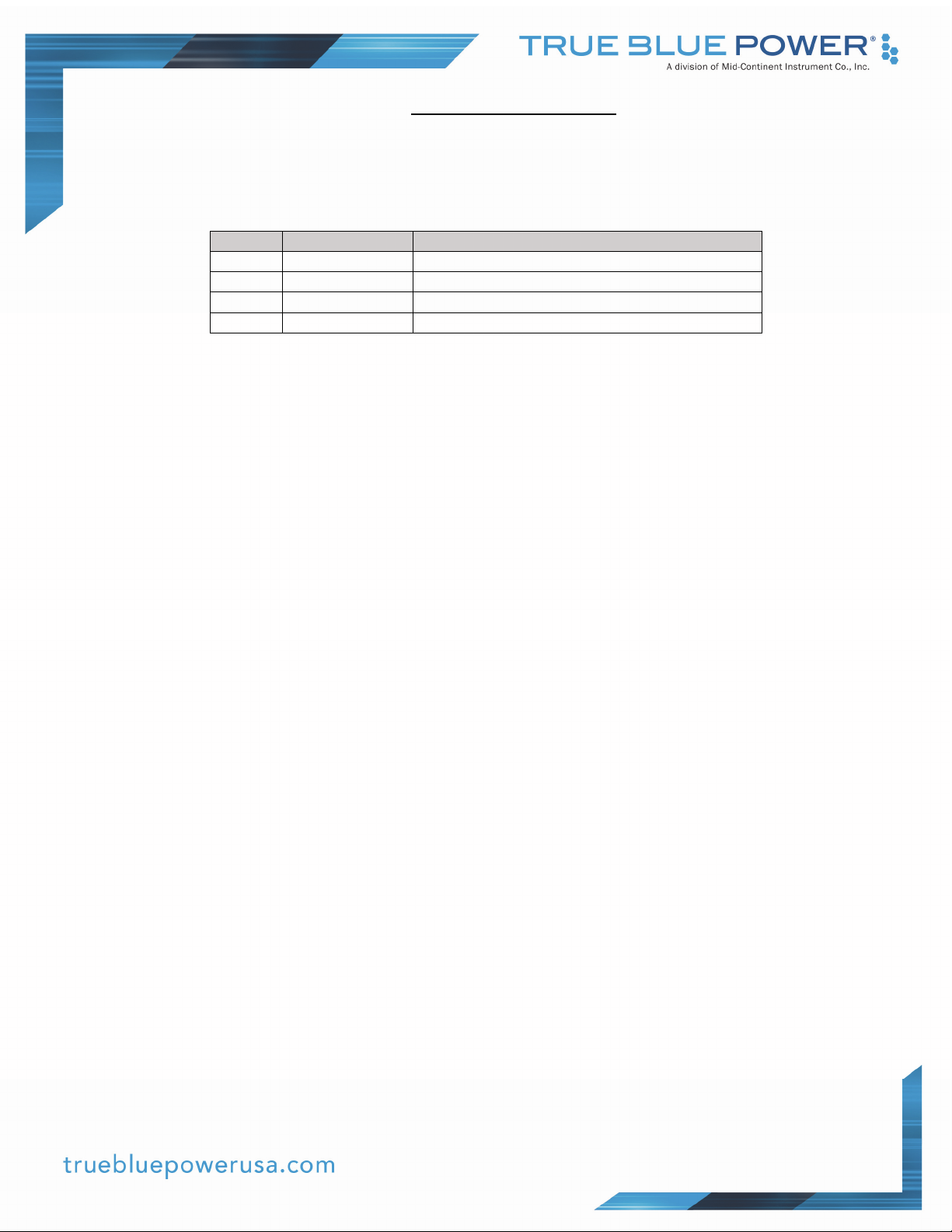
Rev Date Detail Approved
A 12/10/2013 Initial release BAW
B 02/11/2014 Revised Technical Specifications BMC
C 05/27/2014 Revised Section 3.3.1, Wire Gauge Selection BMC
D 01/02/2015 Added TI254 and TI256 models BMC
E 05/11/2015 Added -4 Configuration BMC
F 06/16/2015 Updated -4 Configuration specifications BMC
G
01/06/2017
Update connector Pinout Table to agree with the input
voltage in the Specification Table.
CAS
H 07/26/2019 Updated altitude in Table 1.3 and Qualification sheet. VAA
J 05/04/2020 Updated style and brand to meet Marketing and
Engineering guidelines.
DLR
3 Manual Number 9018067 • Revision J, May 4, 2020
SECTION 1 GENERAL DESCRIPTION
1.1 INTRODUCTION
The model TI250 Series Static Electrical Power Inverter is a lightweight power inverter that
translates a 20 to 36 VDC input to three various output options:
Model Part Number Output
TI250 6430250-1 115 VAC, 60 Hertz
TI254 6430250-2 115 VAC, 400 Hertz
TI256 6430250-3 115/26 VAC, 400 Hertz
TI256 6430250-4 115/26 VAC, 400 Hertz with sync capability
All three configurations provide 250 watts (VA) of power. The alternating current output is defined
as a pure sine wave with less than 2% of total harmonic distortion for clean, noise-free, harmonicfree power to supply loads of corresponding voltage, power and frequency. For the TI250, the
115VAC, 60 Hertz (Hz) is suitable for nearly any common commercial or consumer load rated for a
nominal input of 110-120VAC. The TI254 and TI256 are designed for 115VAC outputs with an AC
frequency of 400 Hz for common avionics and related equipment, with the TI256 also providing an
additional independent 26VAC output and optional dual-unit synchronization. The TI250 Series
Static Inverter is FAA certified to TSO C73 and tested to rigorous environmental standards and
levels of RTCA DO-160. The small size and light weight in conjunction with its installation flexibility
(inside or outside the pressure vessel) make it an ideal choice for aircraft power needs while
reducing the challenges associated with other similar products.
Highlighted features include short circuit protection, overload capability, low voltage shut-down,
temperature monitoring, a self-resettable over-temperature disable, a remote on/off function, and a
fault indication output. The TI250 Series has the same connector of legacy designs plus ground
fault interrupter protection. The rugged extrusion that houses the unit is designed to help dissipate
heat and provide mechanical strength against vibration or other possibilities of damage. The TI250
Series is engineered to run cooler and requires no active cooling, featuring a fanless design, which
saves energy, reduces weight and allows flexible installation locations. At only 2.5 pounds or less,
it is lighter and smaller than competing inverters. Additionally, the primary stage of the TI250
Series utilizes current mode control for increased reliability and safety.
4 Manual Number 9018067 • Revision J, May 4, 2020
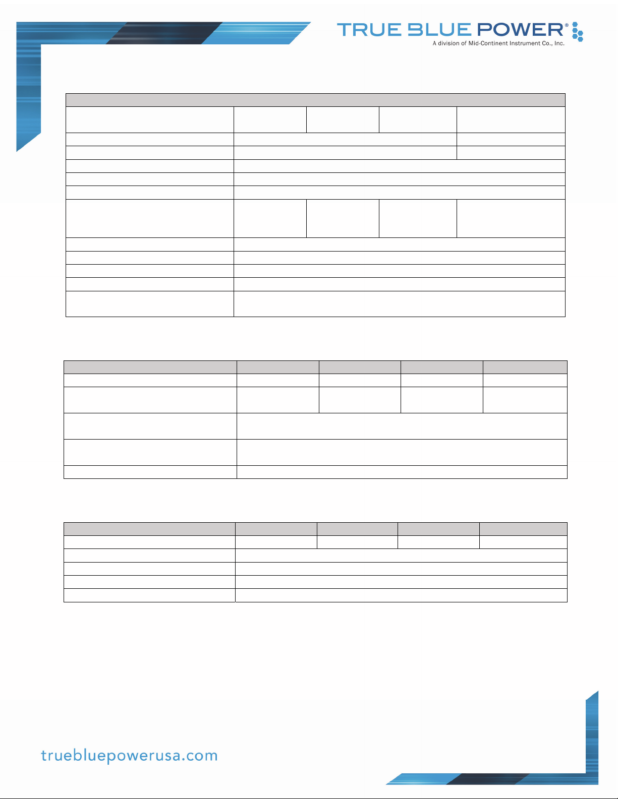
1.2 TECHNICAL SPECIFICATIONS
Electrical Attributes
Model
TI250
Model
TI254
Model TI256 Model TI256
Input Voltage 28VDC nominal; 20-36VDC 18-36VDC
Input Current (full load) 10 amps nominal; 15 amps max 20A max
Input Current (no load) 150 milliamps
Input Current (ON/OFF = OFF) 50 milliamps
Recommended Circuit Breaker 15 amps
Output Voltage
115VAC
±3% at 60
Hertz ±0.1%
115VAC
±3% at 400
Hertz ±0.1%
115/26VAC
±3% at 400
Hertz ±0.1%
115/26VAC
±3% at 400
Hertz ±0.1%
Output Power 250 watts (250 VA at power factor = 1)
Output Waveform Single phase, pure sine wave
Power Factor -0.8 to +0.8
Efficiency 87 – 90% nominal
Total Harmonic Distortion
(THD)
Table 1.1
Less than 2%
Physical Attributes
Model TI250 Model TI254 Model TI256 Model TI256
Weight:
Dimensions:
(not including connector mate)
Mating Connector (and cable
clamp):
2.2 lbs
(1 kg)
6.7 inches long x 6.0 inches wide x 2.0 inches high
(171 mm long x 152 mm wide x 51 mm high)
MS3106A-18-9S (MCI P/N 9016905-1, -2)
2.2 lbs
(1 kg)
2.6 lbs
(1.15 kg)
2.6 lbs
(1.15 kg)
Mounting: Base mount – orientation not critical
Table 1.2
Qualifications
Model TI250 Model TI254 Model TI256 Model TI256
Certification: FAA TSO-C73
Environmental Qualification: RTCA DO-160G Environmental Category; See Section 5.2
Altitude: -15,000 feet to +70,000 feet
Temperature: -55°C to +70°C (-67°F to +158°F)
Table 1.3
5 Manual Number 9018067 • Revision J, May 4, 2020
 Loading...