

Page 1
Revision D • May 4, 2020
Page 2
FOREWORD
This manual provides information intended for use by persons who, in accordance with current
regulatory requirements, are qualified to install this equipment. If further information is required,
please contact:
True Blue Power
c/o Mid-Continent Instrument Co., Inc.
Attn: Customer Service Dept.
9400 E. 34th St. N.
Wichita, KS 67226 USA
Phone 316-630-0101
Fax 316-630-0723
www.truebluepowerusa.com
www.mcico.com
We welcome your comments concerning this manual. Although every effort has been made to
keep it free of errors, some may occur. When reporting a specific problem, please describe it
briefly and include the manual part number, the paragraph/figure/table number and the page
number. Send your comments to:
True Blue Power
c/o Mid-Continent Instrument Co., Inc.
Attn: Technical Publications
9400 E. 34
th
St. N.
Wichita, KS 67226 USA
Phone 316-630-0101
Fax 316-630-0723
Download the current
version of this
installation manual
using your
© Copyright 2017
Mid-Continent Instrument Co., Inc.
smartphone or tablet.
1 Manual Number 9018787 • Revision D, May 4, 2020
Page 3
TABLE OF CONTENTS
SECTION 1 GENERAL DESCRIPTION 4
1.1 INTRODUCTION 4
1.2 TECHNICAL
SECTION 2 PRE-INSTALLATION CONSIDERATIONS 6
2.1 COOLING 6
2.2 EQUIPMENT
2.3 ROUTING
2.4 LIMITATIONS 6
2.5 MODIFICATION 7
SECTION 3 INSTALLATION 8
SPECIFICATIONS 5
LOCATION 6
OF CABLES 6
3.1 GENERAL INFORMATION 8
3.2 UNPACKING
3.3 CABLE
AND INSPECTING EQUIPMENT 8
HARNESS 8
3.4 MOUNTING 13
3.5 INSTALLATION
3.6 INSTALLATION
CAUTIONS 14
COMPLETION 14
SECTION 4 OPERATION 16
4.1 ELECTRICAL PERFORMANCE 16
4.2 PROTECTIVE
4.3 RATED
OUTPUT AT ALTITUDE 17
FEATURES 16
SECTION 5 CONFORMANCE 18
5.1 INSTRUCTIONS FOR CONTINUED AIRWORTHINESS 18
5.2 ENVIRONMENTAL
QUALIFICATION STATEMENT 18
2 Manual Number 9018787 • Revision D, May 4, 2020
Page 4
REVISION HISTORY
Rev Date Detail Approved
A 08/18/2017 Initial release. CAS
B 09/14/2018 Added information for 230V and 400Hz models. CAS
C 11/08/2019 Added notes to 3-phase section, 0.3A input at no load CAS
D 05/04/2020
Updated style and brand to meet Marketing and
Engineering guidelines.
DLR
3 Manual Number 9018787 • Revision D, May 4, 2020
Page 5
SECTION 1 GENERAL DESCRIPTION
1.1 INTRODUCTION
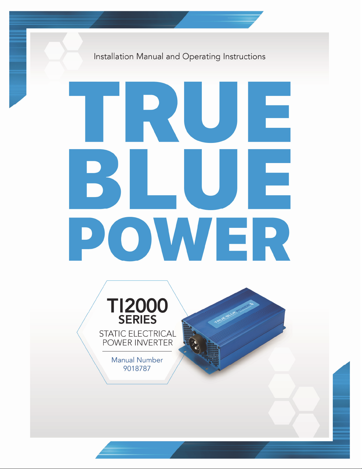
The model TI2000 Series Static Electrical Power Inverter is a lightweight power inverter that
translates a 20 to 36 VDC input to a variety of application options:
Configurations
Model Part Number Output Typical Application
TI2000 6432000-1 115 VAC, 60 Hz General Purpose 115V cabin power
TI2002 6432000-2 230 VAC, 50 Hz General purpose 230V cabin power
TI2004 6432000-4 115 VAC, 400 Hz General purpose 400 Hz aircraft power
Table 1.1
All configurations of the Model TI2000 Series provide 2000 watts (VA) of output power. The
alternating current output is defined as a pure sine wave with less than 3% of total harmonic
distortion for clean, noise-free, harmonic-free power to supply loads of corresponding voltage,
power and frequency. For the TI2000, the 115 VAC 60 hertz (Hz) is suitable for nearly any
common commercial or consumer load rated for a nominal input of 115 VAC. The TI2002 is
designed for a 230VAC output with an AC frequency of 50 Hz for international equipment. The
TI2004 is designed to meet 115VAC 400Hz for aircraft system uses.
The TI2000 Series Static Inverter is FAA certified to TSO C73 and tested to rigorous environmental
standards and levels of RTCA DO-160G. The small size and light weight in conjunction with its
installation flexibility (inside or outside the pressure vessel) make it an ideal choice for aircraft
power needs while reducing the challenges associated with other similar products.
Highlighted features include short circuit protection, overload capability, low voltage shut-down,
temperature monitoring, a self-resettable over-temperature disable, and a remote on/off function.
The rugged extrusion that houses the unit is designed to help dissipate heat and provide
mechanical strength against vibration or other possibilities of damage. Two independent fans allow
for a smaller unit and quiet operation, and keep the internal components cool extending the life of
the unit.
4 Manual Number 9018787 • Revision D, May 4, 2020
Page 6
1.2 TECHNICAL SPECIFICATIONS
Electrical Attributes
6432000-1 6432000-2 6432000-4
Input Voltage: Rated 28VDC nominal; 20-36VDC certified.
Input Power: 80 amps @ 28VDC and 2000W; 0.3 amps at no load
Output Voltage:
115VAC ±3% at 60
Hz ±0.5% (single
phase)
230VAC ±3% at 50
Hz ±0.5% (single
phase)
Output Power: 2000 watts (2000 VA at power factor = 1)
Output Waveform: Single phase pure sine wave
Power Factor: -0.8 to +0.8
Efficiency: 93% nominal
Total Harmonic
Distortion (THD):
< 3%
Table 1.2
Physical Attributes
Weight: 7.7 pounds (not to exceed +5%)
Dimensions:
(not including connector
mate)
Mating Connector (and cable
clamp):
12.00 inches long x 6.32 inches wide x 3.46 inches
high
MCI P/N 9018784-1 and 9018550-2
Mounting: Base mount – orientation not critical
115VAC ±3% at
400 Hz ±0.5%
(single phase)
Table 1.3
Qualifications
Qualification: FAA TSO-C73
Environmental Qualification:
RTCA DO-160G Environmental Category; See Section
5.2
Altitude: 55,000 ft.
Temperature: -55°C to +70°C (-67°F to +158°F)
Table 1.4
5 Manual Number 9018787 • Revision D, May 4, 2020
Page 7

SECTION 2 PRE-INSTALLATION CONSIDERATIONS
2.1 COOLING
No external cooling is required. The unit is equipped with two internal DC fans. Restriction to
airflow can cause overheating of the unit and limit performance or reduce the expected life of the
product. Make sure to provide adequate clearance on both ends of the unit with the hexagonal
openings to allow for proper circulation. In general, four to six inches of clearance on both ends of
the unit should be acceptable. Mounting the unit to a metal surface can also help reduce the
effects of temperature within the unit but is not required.
2.2 EQUIPMENT LOCATION
The TI2000 Series Static Inverter is designed for mounting flexibility, allowing for installation inside
or outside the pressure vessel with no requirement for temperature control. In addition to altitude
and temperature resistance, the unit is also designed to withstand high levels of condensing
humidity.
Installation locations where the unit could be subject to standing or direct water exposure should
be avoided. The unit can be mounted in any orientation. Clearance should be provided for the
mating connector and may require as much as five inches past the unit connector to allow for back
shell access to the connector.
2.3 ROUTING OF CABLES
The wires and cable bundle associated with the unit are heavy gauge wire and carry significant
power. Be aware of routing cables near other electronics or with other wire bundles that may be
susceptible to high energy flow.
Avoid sharp bends in cabling and routing near aircraft control cables. Also avoid proximity and
contact with aircraft structures, avionics equipment, or other obstructions that could chafe wires
during flight and cause undesirable effects.
2.4 LIMITATIONS
The TI2000 Series of static electric power inverters is certified to FAA TSO-C73 with the following
limitations identified:
1. Alternating current (AC) output is provided at 115 volts and 60 Hertz in lieu of 115 volts and
400 Hertz as identified in the MPS of the TSO. This applies to the TI1200 models.
Performance complies fully with all tests and requirements of the MPS of the TSO
accordingly.
2. Alternating current (AC) output is provided at 230 volts and 50 Hertz in lieu of 115 volts and
400 Hertz as identified in the MPS of the TSO. This applies to the TI1202 models.
3. Alternating current (AC) output is provided at 115 volts and 400 Hertz as identified in the
MPS of the TSO. This applies to the TI2004.
4. Equivalent environmental qualification was verified per RTCA DO-160G in lieu of those
identified within the MPS of the TSO.
5. Output power is limited at high altitude and temperature per Figure 4.1.
6 Manual Number 9018787 • Revision D, May 4, 2020
Page 8
The conditions and tests for TSO approval of this article are minimum performance standards.
Those installing this article, on or in a specific type or class of aircraft, must determine that the
aircraft installation conditions are within the TSO standards, specification of the article, and
deviations as listed above. TSO articles must have separate approval for installation in an aircraft.
The article may be installed only according to 14 CFR part 43 or the applicable airworthiness
requirements.
2.5 MODIFICATION
This product has a nameplate that identifies the manufacturer, part number, description,
certification(s) and technical specifications of the unit. It also includes the “MOD” or modification
number representing notable changes in the hardware design of the unit.
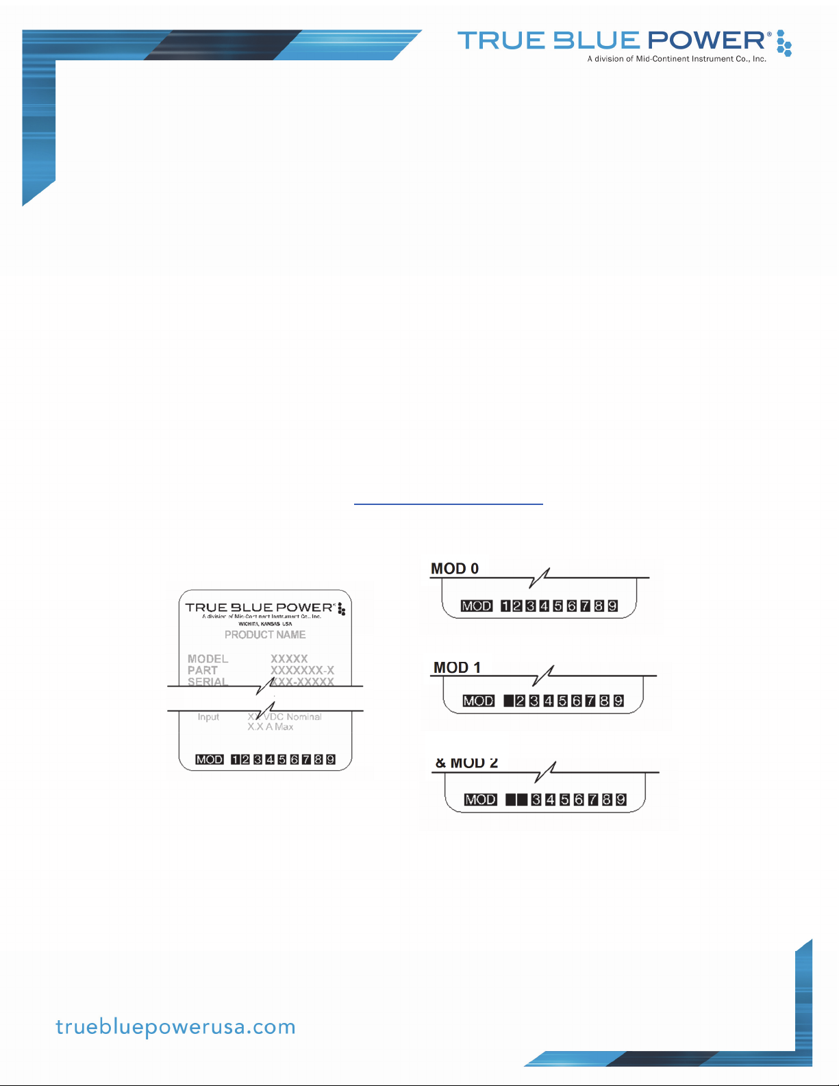
Modification (MOD) 0 is the initial release of the product and is identified on the nameplate by the
lack of marking on the MOD numbers 1 through 9 (i.e. 1-9 are visible). All subsequent
modifications are identified on the nameplate by the marking/blacking out of that particular MOD
number (i.e. for MOD 1, the number 1 is not visible and 2-9 are visible - see Figure 2.1 for
examples). MODs do not have to be sequentially inclusive and may be applied independent of
each other.
For additional details regarding specific changes associated with each MOD status refer to the
product published Service Bulletins at www.truebluepowerusa.com.
MOD 0
MOD 1
MOD 1
& MOD 2
Figure 2.1
Nameplate and MOD Status Example
7 Manual Number 9018787 • Revision D, May 4, 2020
Page 9
SECTION 3 INSTALLATION
3.1 GENERAL INFORMATION
This section contains interconnect diagrams, mounting dimensions and other information
pertaining to the installation of the TI2000 Series Static Inverter. After installation of cabling and
before installation of the equipment, ensure that power is applied only to the pins specified in the
interconnect diagram.
3.2 UNPACKING AND INSPECTING EQUIPMENT
When unpacking this equipment, make a visual inspection for evidence of any damage that may
have occurred during shipment. The following parts should be included:
A. Static Inverter MCI P/N 6432000-( )
B. Installation Manual MCIA P/N 9018787
Available Equipment:
A. Mating Connector (& cable clamp) MCI P/N 9018784-1 and 9018550-2
Equipment not provided:
A. Cable Harness Wire See Section 3.3 for specifications
B. Mounting Hardware four (4) ¼-20 pan head screws
¼” lock washers (optional)
3.3 CABLE HARNESS
Construct the cable harness with regards to the instructions below, and using the Connector Pinout
of Figure 3.3, Table 3.3, and Wiring Diagram of Figure 3.4.
Refer to Section 2: Installation Considerations in regards to routing precautions.
Wire Gauge Selection
Use of PTFE, ETFE, TFE, Teflon, or Tefzel insulated wire is recommended for aircraft use.
The following wire gauges are recommended for each of the pins in the connector:
Pin A and G - 6 AWG stranded
Pin B and D - 24 AWG stranded
Pin C and E - 14 AWG stranded
Pin F - 16-24 AWG stranded
8 Manual Number 9018787 • Revision D, May 4, 2020
Page 10
Pin Assignment Information
3.3.2.1 Input Power
(Pin A) Positive DC input – +20 to 36 VDC. Connect to the aircraft 28 VDC bus.
(Pin G) Negative DC input – Internally the VDC Return pin is connected to the
inverter enclosure. Connect to aircraft ground.
Note: Two common methods for the connecting the negative DC input of power
devices in aircraft are:
1. The negative lead connects from the device to the negative power bus.
2. The negative lead connects from the device to the negative power bus, and a
second lead connects to the aircraft structure close to the power device.
The TI2000 Series passes DO-160G Section 21 conducted emissions testing using
both methods as listed in Section 5.2 of this report.
3.3.2.2 Inverter Output
(Pin C) AC Output – 115VAC, 60Hz, 400Hz or 230VAC, 50Hz. Used for powering
devices where terrestrial/utility power designations are used, this would be
connected as “Line” or “Hot”.
(Pin E) AC Return – Used for powering devices where terrestrial/utility power
designations are used, pin E can be connected as “Neutral”.
3.3.2.3 Circuit Breakers on Inverter Output
Installation of circuit breakers on the DC input and AC output is recommended.
Select values appropriate for the application requirements, with particular
consideration for the chosen wire sizes.
3.3.2.4 Three-Phase Communication
(Pin B and Pin D) RS485P and RS485N – Use a twisted pair to connect these to the
master unit (Phase A unit) to synchronize operation as a three-phase system.
3.3.2.5 Inverter Remote On/Off Controll (see section 4.2.1)
(Pin F) Remote ON/OFF Enable Control – Connecting this pin to DC Return (pin G)
will enable the AC output of the inverter. Install a switch to allow remote on/off
control of the unit. This pin is internally pulled to 11VDC with a limit of 1mA.
3.3.2.6 Fault Status
(Pin H) Fault – Grounded output signal, typically connected to an indicating LED or
lamp, showing that the unit is experiencing a fault condition
9 Manual Number 9018787 • Revision D, May 4, 2020
Page 11
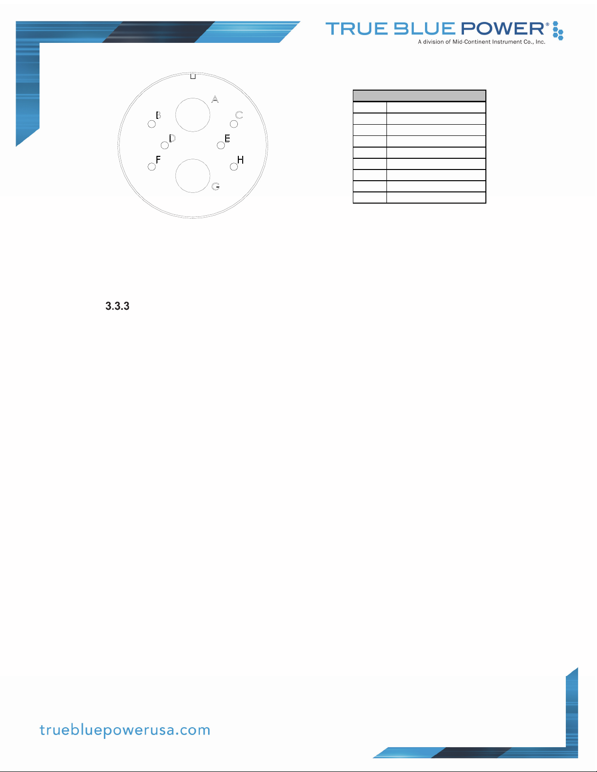
Figure 3.1 Table 3.1
Pinout View of Unit Connector Connector Pinout
Use with GFI, Noisy Electronics, and Other Earth/Neutral Situations
The TI2000 series of inverters is fully electrically isolated from the DC input as indicated by
TSO-C73, and provides a balanced AC output where AC output and AC return are not
associated with the inverter case ground. This is different from terrestrial AC systems
where Neutral is connected to ground at an AC distribution transformer at the power mains.
Some consumer items contain internal power supplies that require an Earth-Neutral
connection for their noise filters to work properly. Similarly, some GFI protection will not
function properly if there is not an Earth/Neutral connection or if there is noise between
Earth and Neutral.
If consumer video electronics exhibit noise interference, if touch-screen devices exhibit
erratic touch-screen operation, or if added GFI systems exhibit false-tripping, then it is
recommended to place a capacitor between the inverter AC return (pin E) and the inverter
chassis ground or airframe. This capacitor can be located anywhere between the inverter
output and the further-most AC outlet. A film capacitor, metalized polyester or metalized
polypropylene with a value between 0.047uF and 0.1uF rated for at least 200VAC (for
115VAC inverter output voltage) or 300VAC (for 230VAC inverter output voltage) can be
used.
Connector Pinout
Pin #
A 20-36VDC Input
B RS485P
C VAC Out put
D RS485N
E Output Return
F Remote On/Off
G VDC Return
H Fault
10 Manual Number 9018787 • Revision D, May 4, 2020
Page 12
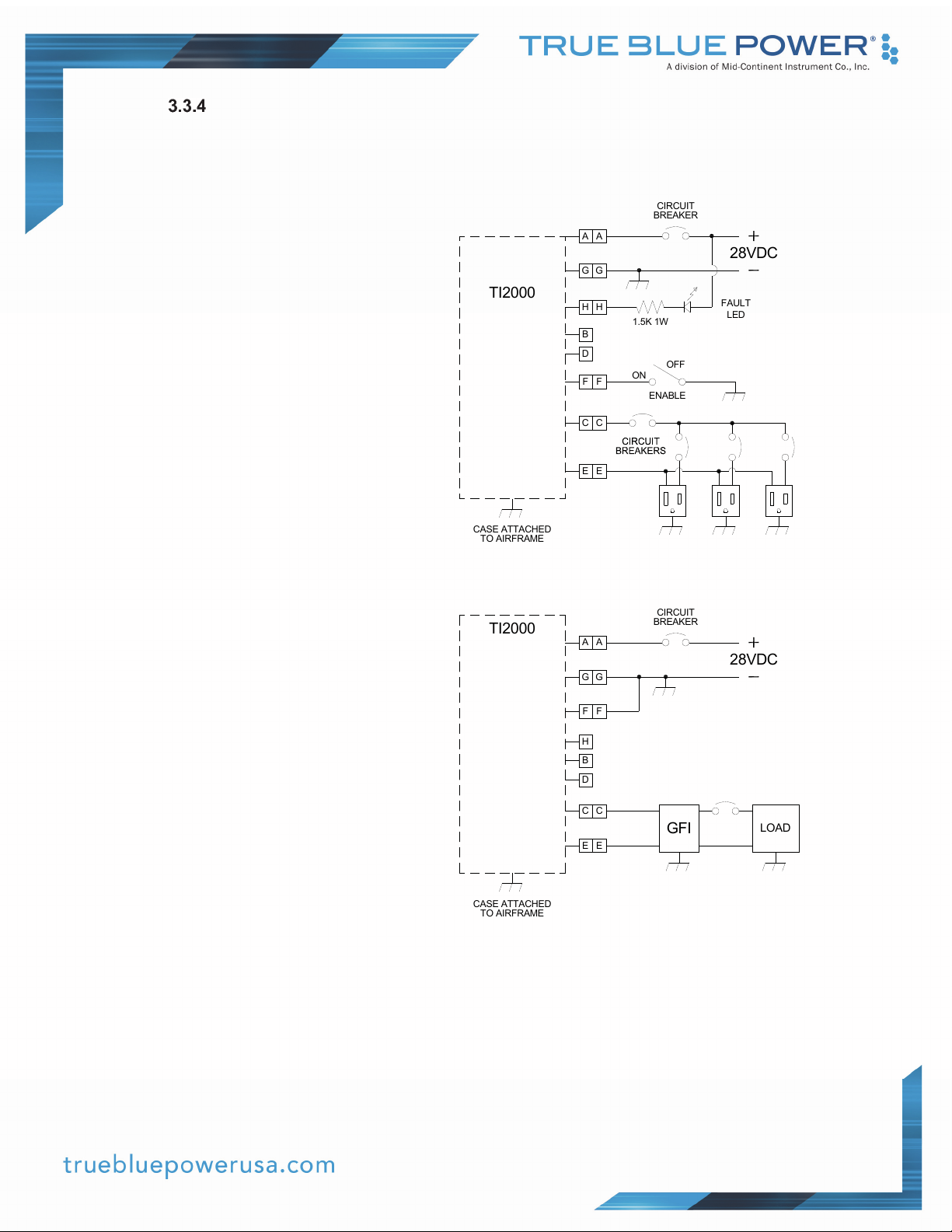
Wiring Examples
The wiring diagrams of Figure 3.4 provides general examples of typical installations. The
configuration of individual aircraft installations may vary.
CIRCUIT
BREAKER
A
TI200
A
G
G
0
H
H
B
D
F
C
E
1.5K 1W
OFF
O
N
F
C
E
ENABL
E
28VDC
FAULT
LED
CASE ATTACHED
TO AIRFRAME
TI200
0
CASE ATTACHED
TO AIRFRAME
CIRCUIT
BREAKER
A
A
28VDC
G
G
F
F
H
B
D
C
C
E
E
GFI
LOA
D
Figure 3.2
Example Wiring Diagrams
11 Manual Number 9018787 • Revision D, May 4, 2020
Page 13
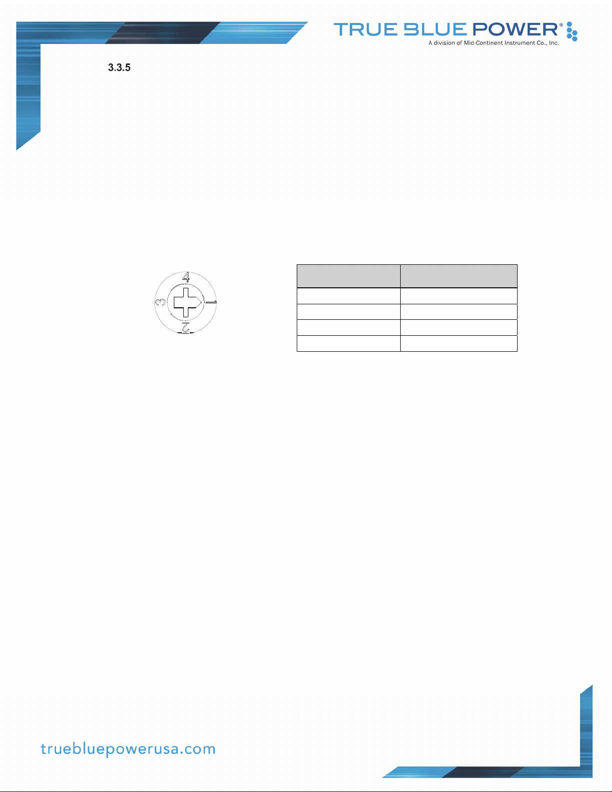
Three-Phase Configuration
The TI2000 series of inverters are capable of operating in a three-phase configuration by
using three units interconnected as shown in figure 3.4. Connect the RS485P and RS485N
pins to each unit, and set the unit phase switch to the correct positions. The switch is
located behind the decal cover located in the middle of the fan intake side of the unit as
shown in figure 3.5. The switch must be set before applying power. For single-phase / solo
operation, the switch must remain in position 1.
For three-phase operation, REMOTE ON must be permanently connected to DC return.
System must be controlled through the application of DC power to the three units
simultaneously. External monitoring of individual units FAULT outputs and/or power
outputs is recommended to ensure all three phases are operating normally.
Phase Switch Phase
1 Single Phase (Solo)
2 Phase A (Master)
3 Phase B (Slave)
4 Phase C (Slave)
Figure 3.3 Table 3.2
Phase Switch Phase Configuration
12 Manual Number 9018787 • Revision D, May 4, 2020
Page 14
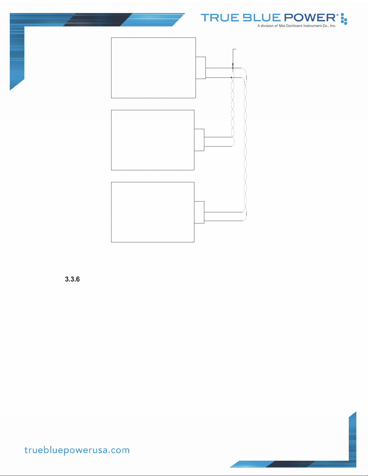
Signal s B and D of 3 phases
TI2000
Phase A
(Master)
Switch in Positi on 2
B
D
att ached t ogether
T. P.
Harness Verification
With the TI2000 Series Static Inverter disconnected, activate the aircraft power bus that
supplies the unit and use a multi-meter to verify that aircraft power and ground with
appropriate voltage is on the pins within the mating harness.
3.4 MOUNTING
TI2000
Phase B
(Slave)
Swi tc h i n Posi t i on 3
TI2000
Phase C
(Slave)
Swi tc h i n Posi t i on 4
B
D
T. P.
B
D
Figure 3.4
Example Three Phase Interconnection
Refer to Section 2: Installation Considerations in regards to equipment location.
The TI2000 Series Static Inverter is designed for base mounting only (in any orientation). Four ¼20 mounting holes should be provided in the aircraft in accordance with Figure 3.5. Secure the unit
with four ¼-20 pan head Phillips screws, or equivalent. A lock-washer under the head of each
screw is recommended.
13 Manual Number 9018787 • Revision D, May 4, 2020
Page 15

3.5 INSTALLATION CAUTIONS
CAUTION
The TI2000 is not protected against reverse polarity on the input 28VDC. Verify the voltage polarity
on the connector before connecting to the TI2000 for the first time.
The TI2000 inverter does not have the ability to phase sync the output to other AC power sources.
Do not connect the output of the TI2000 to any other inverter or AC source or damage to the
TI2000 will result.
NOTE – Digital meters measure AC voltage with a very high impedance. As noted in Section 3.3.3,
the TI2000 has a balanced AC output that is not referenced to the chassis. If a digital meter is used
to measure the AC output to chassis, the reading will correspond to approximately half of the
inverter rated output voltage. This reading may vary depending upon the presence of an optional
noise capacitor (Section 3.3.3), permanently wired accessories, or presence of an external GFI.
However, this voltage is not a problem and is a result of using a high-impedance meter to measure
AC voltages.
3.6 INSTALLATION COMPLETION
Prior to operating the unit in the aircraft, it is recommended to verify the output and functionality of
the unit. In order to prevent accidental damage to other systems, it is best not attach the output to
other equipment or power busses prior to verification.
Verify the output of the unit at the terminating end of the cable with a multi-meter to ensure proper
voltage and polarity. Once verified, installation can be completed and functionality of the remote
on/off feature (if used) should be checked.
14 Manual Number 9018787 • Revision D, May 4, 2020
Page 16
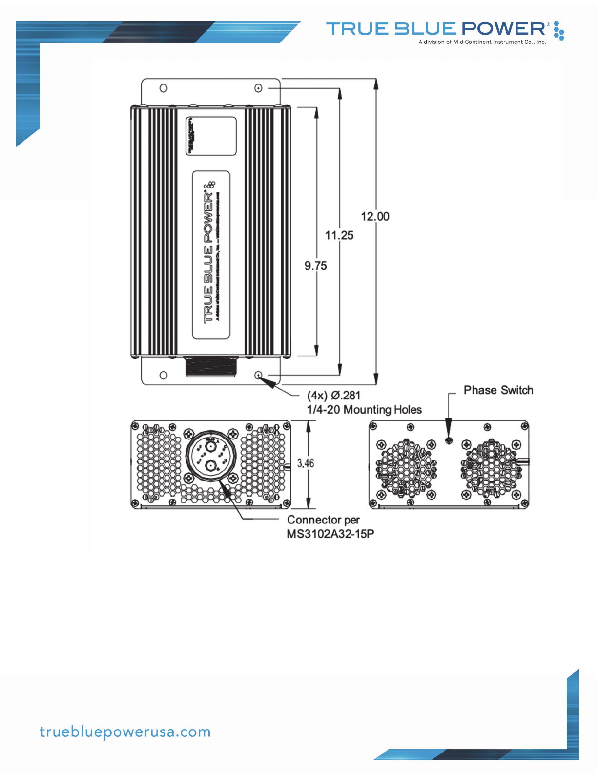
Fan Air Exhaust at connector End Fan Air Intake at this end of Inverter
Figure 3.5
TI2000 Series Outline Drawing
15 Manual Number 9018787 • Revision D, May 4, 2020
Page 17
SECTION 4 OPERATION
4.1 ELECTRICAL PERFORMANCE
The TI2000 Series Static Inverter converts a direct current (DC) voltage input to a regulated, pure
sine wave alternating current (VAC) output. Different models provide for outputs of 115 VAC 60 or
400 Hz, and 230 VAC 50 Hz. The unit is capable of providing 2000 watts to power a variety of
aircraft accessories including laptops, personal electronics, onboard systems, and many others
(See Table 1.2 for tolerance ranges).
The unit is designed as a two-stage, solid-state switch-mode power supply. The power
transformation utilizes a first-stage push-pull methodology followed by an H-bridge AC forming
second stage. The primary stage utilizes ‘current-mode’ control providing instantaneous load
protection as an advantage over legacy designs that incorporate ‘voltage-mode’ controllers. The
alternating current is frequency controlled using a crystal oscillator reference.
4.2 PROTECTIVE FEATURES
Remote On/Off
The TI2000 Series Static Inverter incorporates a remote on/off feature that allows the user
to enable or disable the output of the unit. By providing a ground on the appropriate pin
(See Table 3.3) the user, via a remote mounted switch or similar method, can enable the
output of the unit. The unit can be similarly disabled by removing the ground signal (open
circuit) to the same pin.
Over-Voltage
When the input voltage exceeds the operating range of the unit (See Table 1.1; absolute
maximum input of 36VDC) the unit senses an over-voltage condition and disables the
output. The unit will dynamically monitor the input voltage such that if the input returns to
within the normal operating range, the output will be enabled and allow the unit to operate
normally.
Under-Voltage
When the input voltage drops below the operating range of the unit (See Table 1.1;
absolute minimum input of 20VDC) the unit senses an under-voltage condition and disables
the output. The unit will monitor the input voltage such that if the input returns to within the
normal operating range, the output will be enabled and allow the unit to operate normally.
Over-Temperature
The TI2000 Series incorporates an internal temperature sensing device that provides
monitoring and feedback to the control circuits. When the unit senses an internal condition
that exceeds maximum temperature, the inverter output is disabled and the internal cooling
fans will continue to operate. The unit output will be enabled when the temperature returns
to within acceptable limits. This over-temperature reset occurs automatically without any
external intervention required.
16 Manual Number 9018787 • Revision D, May 4, 2020
Page 18
Short Circuit and Over-Current
The TI2000 Series is capable of surviving a short circuit or over-current event without
permanent damage or effect to long-term reliability. The unit can provide over its rated
power output up to 110% of rating or 2200 VA continuously. The power output is limited by
temperature, input voltage and altitude as shown in Figure 2.1.
At full short circuit, the unit can momentarily provide 3200 VA. After 2 seconds, the AC sine
wave output is clipped and the inverter will only draw around 10 amps from the 28V input. If
the short circuit is removed within 8 seconds, the inverter will return to full power, otherwise
the output will shut off until the enable or the power input is cycled off and on again.
Temperature Regulated Cooling
The unit is equipped with two internal brushless DC fans for cooling to extend the power
range and long-term life. The fans are activated at a specified point determined by the
continuous monitoring of the internal temperature. The fans operate very quietly to reduce
the audible noise in any environment. The two fans provide independent redundancy for
protection of the unit in the event that one becomes inoperative.
4.3 RATED OUTPUT AT ALTITUDE
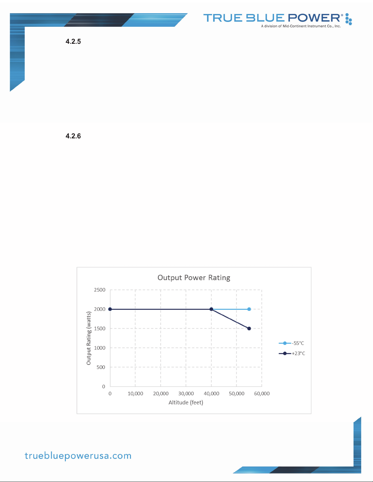
The output power rating is affected by the combination of altitude and temperature, per Figure 4.1.
Above 40,000 feet, an ambient temperature above 23°C will limit the output to less than full power.
In all cases, the protection within TI2000 will automatically power off the unit to prevent any
damage should any condition cause high internal temperatures.
Figure 4.1 – Output Power Rating
17 Manual Number 9018787 • Revision D, May 4, 2020
Page 19
SECTION 5 CONFORMANCE
5.1 INSTRUCTIONS FOR CONTINUED AIRWORTHINESS
No periodic scheduled maintenance or calibration is necessary for continued airworthiness of the
TI2000 Series Static Inverter. If the unit fails to perform to specifications, the unit must be removed
and serviced by Mid-Continent Instruments and Avionics or their authorized designee.
.
5.2 ENVIRONMENTAL QUALIFICATION STATEMENT
MODEL NUMBER: TI2000, TI2002, TI2004 PART NUMBER: 6432000-( ) Series
DESCRIPTION: Static Electrical Power Inverter CERTIFICATION: FAA TSO-C73
MANUFACTURER: True Blue Power, a division of Mid-Continent Instrument Co., Inc.
ADDRESS: 9400 E. 34th St. North, Wichita, KS 67226, USA.
SPECIFICATION: Test Specification (TS) 710 Test Data Sheet (TDS) 710
STANDARD: RTCA DO-160, Rev G, dated 12/08/10
CONDITIONS SECTION DESCRIPTION OF TEST
Temperature and Altitude 4 Category F2
Temperature Variation 5 Category S2
Humidity 6 Category B
Operational Shock and Crash Safety 7 Category B
Vibration 8 Category U; Curve G
Explosion 9 Category X
Waterproofness 10 Category X
Fluids 11 Category X
Sand and Dust 12 Category X
Fungus 13 Category X
Salt Spray 14 Category X
Magnetic Effect 15 Category Z
Power Input 16 Category B(XX)
Voltage Spike 17 Category B
Audio Frequency Conducted Susceptibility 18 Category R
Induced Signal Susceptibility 19 Category X
Radio Frequency Susceptibility 20 Category X
Emission of Radio Frequency Energy 21 Category B
Lightning Induced Transient Susceptibility 22 Category X
Lightning Direct Effects 23 Category X
Icing 24 Category X
ESD 25 Category A
Flammability 26 Category X
REMARKS:
18 Manual Number 9018787 • Revision D, May 4, 2020
 Loading...