

True blue power TC2000 Series Installation Manual And Operating Instructions
Installation Manual and Operating Instructions
Model TC2000 Series
Static Electrical Power Converter
True Blue Power
Mid-Continent Instrument Co., Inc.
dba Mid-Continent Instruments and Avionics
9400 E. 34
Wichita, KS 67226 Manual Number 9019049
PH (800) 821-1212 FX (316) 630-0723 Rev C March 8, 2018
th
®
is a division of Mid-Continent Instrument Co., Inc.
Street N.

FOREWORD
This manual provides information intended for use by persons who, in accordance with current
regulatory requirements, are qualified to install this equipment. If further information is required,
please contact:
True Blue Power
c/o Mid-Continent Instrument Co., Inc.
Attn: Customer Service Dept.
9400 E. 34th Street N.
Wichita, KS 67226 USA
PH (316) 630-0101
FX (316) 630-0723
www.truebluepowerusa.com
www.mcico.com
We welcome your comments concerning this manual. Although every effort has been made to
keep it free of errors, some may occur. When reporting a specific problem, please describe it
briefly and include the manual part number, the paragraph/figure/table reference and the page
number. Send your comments to:
True Blue Power
c/o Mid-Continent Instrument Co., Inc.
Attn: Technical Publications
9400 E. 34th Street N.
Wichita, KS 67226 USA
PH (316) 630-0101
FX (316) 630-0723
All products produced by Mid-Continent Instrument, Co., Inc., including those identified as MidContinent Instruments and Avionics or True Blue Power, are designed and manufactured in
Wichita, KS, USA.
Copyright 2017
Mid-Continent Instrument Co., Inc.
Rev C, March 8, 2018 2 Manual Number 9019049

REVISION DETAIL
Revision Date Approved Detail
A 12/28/2017 BAW Initial release
B 01/26/2018 BAW
C 03/08/2018 JRC
Corrected formatting issues. Incorporated FAA
comments.
Changed paragraph 3.3.2.3 pin ‘E’ to pin ‘A’. Added
note page 5 on ground regulatory requirements.
Rev C, March 8, 2018 3 Manual Number 9019049

TABLE OF CONTENTS
SECTION 1 GENERAL DESCRIPTION .................................................................................. 5
1.1 INTRODUCTION ............................................................................................................ 5
1.2 TECHNICAL SPECIFICATIONS .................................................................................... 5
SECTION 2 PRE-INSTALLATION CONSIDERATIONS ........................................................ 6
2.1 COOLING ....................................................................................................................... 6
2.2 EQUIPMENT LOCATION ............................................................................................... 6
2.3 ROUTING OF CABLES .................................................................................................. 6
2.4 LIMITATIONS ................................................................................................................. 6
SECTION 3 INSTALLATION PROCEDURES ........................................................................ 8
3.1 GENERAL INFORMATION ............................................................................................ 8
3.2 UNPACKING AND INSPECTING EQUIPMENT ............................................................ 8
3.3 CABLE HARNESS ......................................................................................................... 8
3.3.1 Wire Gauge Selection ............................................................................................. 8
3.3.2 Pin Assignment Information .................................................................................... 9
3.3.3 Example Wiring Diagrams ..................................................................................... 10
3.3.4 Harness Verification .............................................................................................. 10
3.4 MOUNTING .................................................................................................................. 12
3.5 INSTALLATION COMPLETION ................................................................................... 13
3.6 INSTALLATION CAUTION ........................................................................................... 13
SECTION 4 OPERATION ..................................................................................................... 14
4.1 ELECTRICAL PERFORMANCE .................................................................................. 14
4.2 PROTECTIVE FEATURES .......................................................................................... 14
4.2.1 Remote On/Off ...................................................................................................... 14
4.2.2 Over-Temperature ................................................................................................. 14
4.2.3 Short Circuit And Over-Current ............................................................................. 14
SECTION 5 CONFORMANCE .............................................................................................. 15
5.1 INSTRUCTIONS FOR CONTINUED AIRWORTHINESS ............................................ 15
5.2 ENVIRONMENTAL QUALIFICATION STATEMENT ................................................... 15
Rev C, March 8, 2018 4 Manual Number 9019049
1.1 INTRODUCTION
The model TC2000 Series Static Electrical Power Converter is a lightweight power converter that
translates an aircraft alternating current (AC) input of 115 volts at 360-800 Hertz to a 28 volt
direct current (DC) output. Additionally the TC2000 can be bench operated on AC Mains with
115 or 230 volts at 47-65 Hz input and provide a 28 volt direct current (DC) output (see Note 1
below).
The wide input operating voltage and frequency make the TC2000 suitable for nearly any
common business or commercial aircraft which provides 100-125 VAC between 360-800 Hertz.
The output of 71 amps @ 28 VDC produces 2000 watts of power to supply avionics,
instrumentation, seating, personal charging, lighting, and many other applications. The TC2000
Series Static Converter is FAA certified to TSO-C71 and tested to rigorous environmental
standards and levels of RTCA DO-160G. The small size and light weight in conjunction with its
installation flexibility (inside or outside the pressure vessel) make it an ideal choice for aircraft
power needs while reducing the challenges associated with other similar products.
Highlighted features include short circuit protection, overload capability, low voltage shut-down,
temperature monitoring, a self-resettable over-temperature disable and a remote on/off function.
The TC2000 Series has a robust Military-rated circular connector, and the rugged extrusion that
houses the unit is designed to help dissipate heat and provide mechanical strength against
vibration or other possibilities of damage. Two independent fans allow for a smaller unit and
quiet operation, and keep the internal components cool extending the life of the unit.
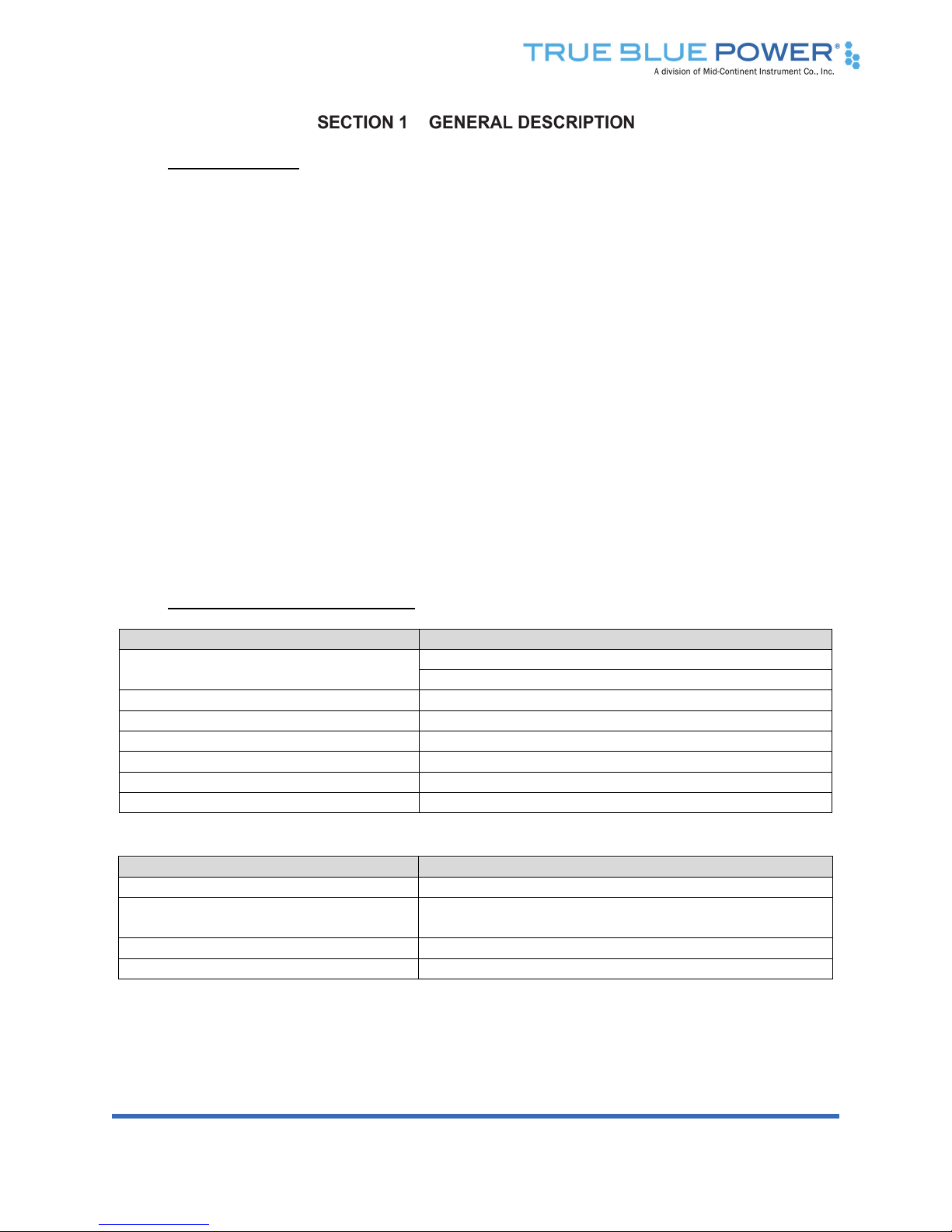
1.2 TECHNICAL SPECIFICATIONS
Electrical Attributes: Model TC2000
Input Voltage
Aircraft: 115VAC nominal, 360-800 Hz.
AC Mains: 115VAC or 230VAC, 47 to 65 Hz. (
Input Current (full load) 22 Amps nominal; 28 Amps max
Input Current (unit off) 2 Amps
Recommended Input Circuit Breaker 30 Amps (for 115VAC aircraft use)
Output Voltage 28VDC ± 0.5 VDC
Output Power 2000 watts (28VDC @ 71 Amps rated)
Efficiency 88% nominal
Table 1.1
Physical Attributes: Model TC2000
Weight: 9.9 lbs [4,49 kg]
Dimensions:
(not including connector mate)
14.00 inches x 6.32 inches x 3.46 inches (LxWxH)
[35,5 x 16,1 x 8,8 cm]
Mating Connector (and cable clamp): MCI P/N 9018993-1 and 9018550-2
Mounting: Base mount – orientation not critical
Table 1.2
Note 1: The TC2000 has not been tested to UL, CE, or other ground regulatory requirements. Powering from AC mains
is intended for testing or temporary use only.
Note 1)
Rev C, March 8, 2018 5 Manual Number 9019049
 Loading...