


Revision J • September 21, 2020
FOREWORD
This manual provides information intended for use by persons who, in accordance with current
regulatory requirements, are qualified to install this equipment. If further information is required,
please contact:
True Blue Power
c/o Mid-Continent Instrument Co., Inc.
Attn: Customer Service Dept.
9400 E. 34th St. N.
Wichita, KS 67226 USA
Phone 316-630-0101
Fax 316-630-0723
www.truebluepowerusa.com
www.mcico.com
We welcome your comments concerning this manual. Although every effort has been made to
keep it free of errors, some may occur. When reporting a specific problem, please describe it
briefly and include the manual part number, the paragraph/figure/table number and the page
number. Send your comments to:
True Blue Power
c/o Mid-Continent Instrument Co., Inc.
Attn: Technical Publications
9400 E. 34
Wichita, KS 67226 USA
Phone 316-630-0101
Fax 316-630-0723
© Copyright 2017
Mid-Continent Instrument Co., Inc.
th
St. N.
Download the current
version of this
installation manual
using your
smartphone or tablet.
1 Manual Number 9018047 • Revision J, September 21, 2020

TABLE OF CONTENTS
SECTION 1 GENERAL DESCRIPTION 4
1.1 INTRODUCTION 4
1.2 PHYSICAL
1.3 UNIT
1.4 TECHNICAL
1.5 IMPORTANT
SECTION 2 PRE-INSTALLATION CONSIDERATIONS 9
2.1 COOLING 9
2.2 EQUIPMENT
2.3 ROUTING
2.4 LIMITIATIONS 10
2.5 MODIFICATION 10
ATTRIBUTES 4
ARCHITECTURE 4
SPECIFICATIONS 5
SAFETY INFORMATION 7
LOCATION 9
OF CABLES 9
SECTION 3 INSTALLATION 11
3.1 GENERAL 11
3.2 PRE-INSTALLATION
INSPECTION 11
3.3 PARTS 11
3.4 INSTALLATION 12
SECTION 4 OPERATION 16
4.1 DESCRIPTION 16
4.2 OPERATIONAL
4.3 ACTIVE
MONITORING 18
MODES 16
SECTION 5 CONFORMANCE 19
5.1 DISPATCH VERIFICATION AND IN-FLIGHT MONITORING 19
5.2 ROUTINE
5.3 COMPONENT
5.4 STORAGE
5.5 END
MAINTENANCE 19
MAINTENANCE 21
INFORMATION 21
OF LIFE 22
5.6 DISPOSAL 22
5.7 ENVIRONMENTAL
QUALIFICATION STATEMENT 23
2 Manual Number 9018047 • Revision J, September 21, 2020
REVISION HISTORY
Rev Date Detail Approved
A 10/17/2013 Initial release. BAW
B 12/10/2013 Miscellaneous revisions to grammar and content. BAW
C 10/23/2015 Updates for MOD 1 monitoring signal definitions and other
BAW
miscellaneous revisions.
D 03/21/2016 Updates for MOD 2 battery operational characteristics;
BAW
added QTR 1727 and DO-160 Sections 10, 12 to Appendix
1 EQF.
E 04/22/2016 Added Modifications section (2.6). WVC
F 06/23/2017 Added 6430017-2 and associated references; revised
WVC
weight to 16.0 lbs; clarified battery storage charge interval.
G 11/01/2017 Removed technical content not required for Installation and
WVC
Operating Instructions.
H 05/04/2020 Updated style and brand to meet Marketing and
DLR
Engineering guidelines. Section 1.5.1, updates to title and
symbols. Inserted Section 5.7, Environmental Qualification
Statement.
J 09/21/2020 Added 6430017-3 and -4 and associated references. VAA
3 Manual Number 9018047 • Revision J, September 21, 2020

SECTION 1 GENERAL DESCRIPTION
1.1 INTRODUCTION
The TB17 series Advanced Lithium-ion Battery, part numbers 6430017-( ), is designed to deliver
high current capability to start piston and light turbine aircraft engines and successively, provide
DC power capacity to the primary electrical bus in the event of generator function loss. The TB17
®
is a sophisticated power system that utilizes state-of-the-art Nanophosphate
lithium-ion battery
cell technology which provides improvements in performance, safety, life and weight when
compared to traditional or competing aircraft batteries. Consideration given to key electrical and
mechanical design principles yield compliance with regulatory standards and meet or exceed
industry expectations. The TB17 is a complete battery solution that provides significant value and
benefit to an aircraft designer, owner and operator.
The TB17 requires professional use and maintenance to deliver maximum performance and value
as designed. This manual contains information related to the specifications, installation, operation,
storage, scheduled maintenance and other related topics associated with the proper care and use
of this product.
1.2 PHYSICAL ATTRIBUTES
The TB17 is a single, integrated component contained in a metal enclosure with positive and
negative power terminals and a 7-pin circular communication connector. The top of the enclosure
supports the use of a hold-down bar for typical aircraft mounting. There is a 1-inch diameter vent
port on top of the unit for an exhaust connection that directs any released emissions appropriately.
1.3 UNIT ARCHITECTURE
The unit is comprised of three primary functional pieces:
Battery modules
“Switch” board; a printed circuit board assembly to control charging and discharging
“Control” board; a printed circuit board assembly to serve as the battery management
system
Each battery module consists of twenty-eight (28) cells, arranged in four strings of seven parallel
cells connected in series. Two modules are connected in series to provide the total battery output.
The modules are designed identically and each includes multiple temperature monitors and a
heater. The cells are connected with welded bus bars which contain an individual fuse for each cell
in the module.
The Switch board incorporates the ability to enable and disable charging or discharging depending
on the health of the battery and associated conditions. It also contains a charge limiting function
and current monitoring.
4 Manual Number 9018047 • Revision J, September 21, 2020
The Control board is the battery management system. The discrete logic circuitry monitors the
battery functions and protects against such conditions as short circuit, over-temperature, overdischarge and others. The Control board also generates the battery status signals that are
accessed through the 7-pin communication connector for cockpit monitoring and heater
functionality control.
Additional components in the unit include Resistance Temperature Detectors (RTDs) that produce
analog electrical signals accessible through the 7-pin connector for redundant temperature
monitoring. There are two RTDs in the 6430017-1/-3 units and one in the 6430017-2/-4 units
(hereafter referred to as -1, -2, -3, and -4, respectively).
1.4 TECHNICAL SPECIFICATIONS
Electrical Attributes
Software / Complex Hardware None
Power Input 28.8 volts DC Nominal, 34A Max
Power Output 26.4 volts DC Nominal, Continuous Current 500A;
Power Peak Current (I
Power Rated Current (I
) 840A;
PP
) 600A
PR
Battery Capacity 17 amp hours (Ah) @ 23°C
Table 1.1
Physical Attributes
Weight
Dimensions (see Figure 1.1)
(not including vent and
connectors)
16.0 pounds (7.2 kg) -1 and -2 configurations
17.1 pounds (7.5 kg) -3 and -4 configurations
7.22 x 7.37 x 6.01 inches -1 and -2 configurations
[183 x 187 x 153 mm]
7.22 x 9.33 x 6.01 inches -3 and -4 configurations
[183 x 237 x 153 mm]
Power Terminals (for -1 and -2) M8 x 1.25 x 10mm deep thread, 13mm hex bolt
Quick Disconnect Power
Receptacle (for -3 and -4)
2-pin per MIL-PRF-18148/3 form factor (MS3509)
Communication Connector 7-pin circular
Mounting Hold down bar (0.31 inch holes on 7.9 inch centers)
Table 1.2
Qualifications
Certification FAA/TSO-C179a; EASA/ETSO-C179a
Performance Qualification RTCA/DO-311 Minimum Operational Performance
Standard for Rechargeable Lithium Battery Systems
RTCA/DO-347 Certification Test Guidance For Small
and Medium Sized Rechargeable Lithium Batteries and
Battery Systems (partial)
Environmental Qualification RTCA DO-160G; See Section 5.7
Table 1.3
5 Manual Number 9018047 • Revision J, September 21, 2020
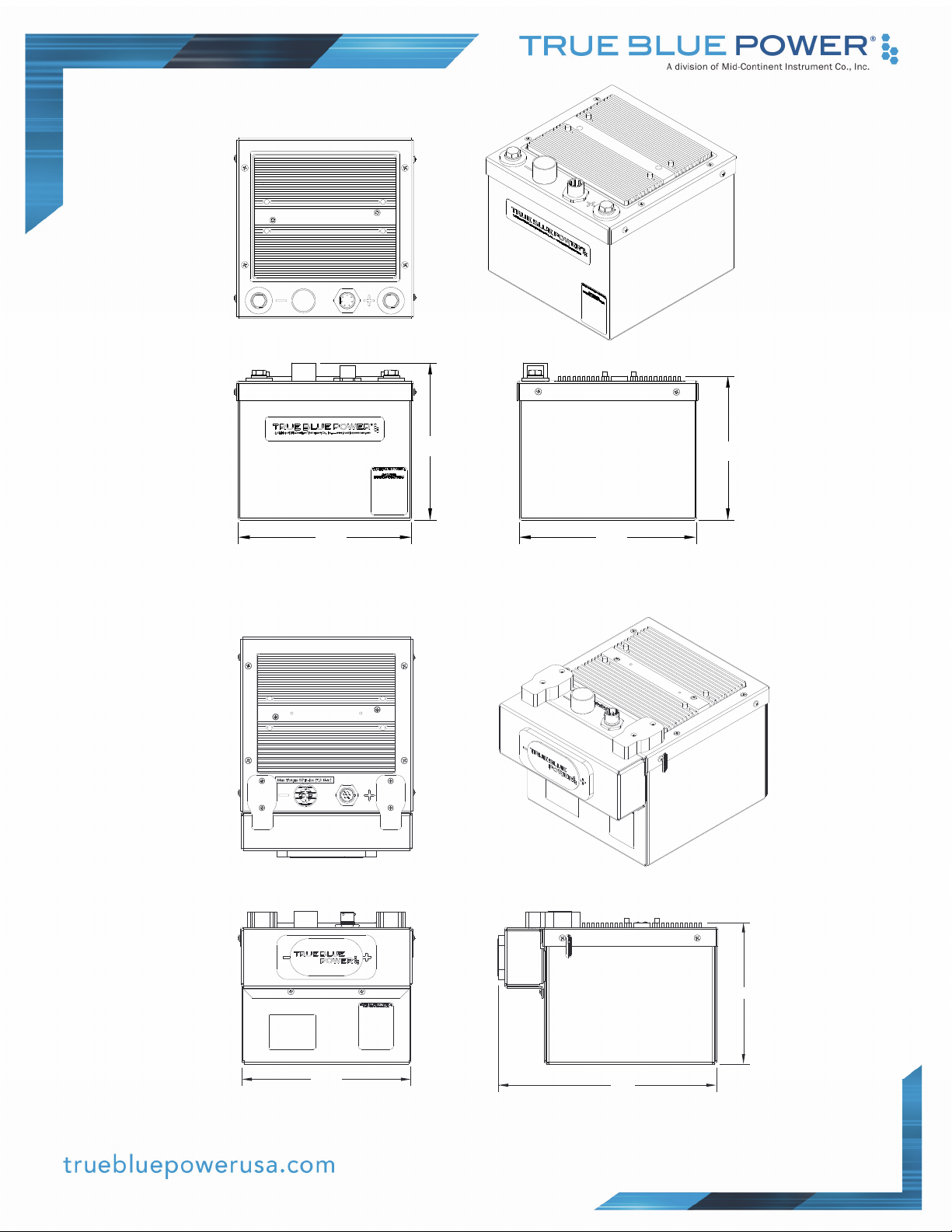
6.56
7.22
Figure 1.1
-1 and -2 Unit Outline Drawing
6.01
7.37
7.22
6.01
9.33
Figure 1.2
-3 and -4 Unit Outline Drawing
6 Manual Number 9018047 • Revision J, September 21, 2020
W
W
1.5 IMPORTANT SAFETY INFORMATION
Read this safety information BEFORE maintaining or servicing the battery.
Symbol Definition
This section describes the precautions necessary for safe operations. The following safety
symbols have been placed throughout the guide.
ARNING
Warnings identify conditions or practices that could result in personal injury.
CAUTION
Cautions identify conditions or practices that could result in damage to the equipment.
Handling Precautions
ARNING
The battery’s energy is high enough to sustain an ARC flash. Always wear safety glasses,
fire retardant smocks, and use insulated tools when servicing the battery.
• Remove metal items such as rings, bracelets, and watches when working with battery
packs. A battery could produce a short circuit current high enough to weld jewelry to
metal and cause a severe burn.
• Always use appropriate Electrostatic Discharge (ESD) protection while working with the
battery pack.
• All connections for battery pack testing must include appropriate short-circuit protection.
• The battery pack service area shall be properly ventilated and egress paths shall be
unobstructed.
• Specialized breathing filters are not required under normal use.
• Always use insulated tools.
• Never smoke or allow a spark or flame near the battery pack.
• Use caution to reduce the risk of dropping a metal tool on the battery. Dropping a tool
could spark or short circuit the battery pack.
• Turn all accessories off before removing the ground terminal.
7 Manual Number 9018047 • Revision J, September 21, 2020

Additional Precautions
The following design and operation factors are required for safe use.
CAUTION
• It is not acceptable to combine or use any battery cells or modules other than those
approved by True Blue Power within this battery pack.
There are no limitations in storing or using this battery in the vicinity of other battery
chemistries. This battery does not emit or absorb any gas during storage, transportation
or during normal operating conditions.
Batteries must not be installed with the output terminals reversed. A reversed battery
could be charged by other batteries in the circuit during discharge; or discharged by the
charging system during charge.
Battery terminals must be covered with non-conductive protective devices to avoid any
possibility of shorting during handling, shipping or storage.
Shipping
True Blue Power lithium-ion cells and batteries are designed to comply with all applicable
shipping regulations as prescribed by industry and regulatory standards. This includes
compliance with the UN recommendations on the Transport of Dangerous Goods, IATA
Dangerous Goods Regulations, and applicable U.S. DOT regulations for the safe transport
of lithium-ion batteries and the International Maritime Dangerous Goods Code. In
accordance with IATA and per UN 3480, PI 965, Section 1A and 1B, the TB17 series
Advanced Lithium-ion Battery will be shipped with a state of charge (SOC) not to exceed
30% of rated capacity. This battery is classified as a Class 9 Dangerous Good. If the
battery requires shipment, please contact the manufacturer for additional instructions on
proper procedures.
CAUTION
NOTE: The unit is shipped with approximately 30% state-of-charge (SOC).
Upon receipt the battery shall be fully charged using the procedures listed in this
manual (prior to storage and again prior to installation/use).
Upon receipt the battery shall be fully charged. Batteries that are stored shall be fully
recharged at a minimum every 6 months, following the procedure set forth in Section 5.2.2.
For more detailed storage instructions refer to Section 5.4.
8 Manual Number 9018047 • Revision J, September 21, 2020

SECTION 2 PRE-INSTALLATION CONSIDERATIONS
2.1 COOLING
No internal or external cooling of the unit is required. The unit is designed to operate over a wide
temperature range and includes internal thermal monitoring and protection circuits. See Section 4
for more details.
2.2 EQUIPMENT LOCATION
The TB17 Advanced Lithium-ion Battery is designed for mounting flexibility, allowing for installation
with no requirement for temperature or pressure control. Although not required, optimum
performance and life can be achieved by mounting the TB17 in a temperature controlled section of
the aircraft. In addition to altitude and temperature tolerance, the unit is designed to withstand high
levels of condensing humidity. However, installation locations where the unit could be subject to
standing or direct water exposure should be avoided. The unit should be mounted in the upright
position (vent on top).
Failure mode, effects, and criticality analysis of the TB17 has shown that the potential for the
release of toxic or flammable gases as a result of any potential condition is extremely
improbable. However, for additional risk mitigation, the unit is designed with a vent which should
be connected and diverted overboard in the event of such an occurrence. Details for vent
installation are provided in Section 3. The unit should not be installed in compartments where lines,
tanks or equipment containing fuel, oil or other flammable fluids are present. Installation near
potential sources of ignition should be avoided.
Consideration should be given to how the status and reporting functions of the battery will be
displayed within the aircraft. At a minimum, critical parameters determined at the time of
certification should be available to the pilot and/or crew. Additionally, existing aircraft systems
which are designed to work with traditional batteries may need alteration in order to accommodate
the slight change in voltage output of this lithium-ion battery and the communication capabilities
available.
2.3 ROUTING OF CABLES
The power terminal wires associated with the unit are heavy gauge wire and carry significant
power. Be aware of routing cables near other electronics or with other wire bundles that may be
susceptible to high energy flow.
Avoid sharp bends in both the power cables and the signal cabling and be cautious of routing near
aircraft control cables. Also avoid proximity and contact with aircraft structures, avionics
equipment, or other obstructions that could chafe wires during flight and cause undesirable effects.
Cables should not run adjacent to heaters, engine exhausts, or other heat sources. The signal
cable bundle wires are recommended to be no smaller than 24 gauge.
9 Manual Number 9018047 • Revision J, September 21, 2020

2.4 LIMITIATIONS
The conditions and tests for TSO approval of this article are minimum performance standards.
Those installing this article, on or in a specific type or class of aircraft, must determine that the
aircraft installation conditions are within the TSO standards. TSO articles must receive additional
installation approval prior to being operated on each aircraft. The article may be installed only
according to 14 CFR Part 43 or the applicable airworthiness requirements.
See Section 2.2 for limitations associated with equipment installation location.
2.5 MODIFICATION
This product has a nameplate that identifies the manufacturer, part number, description,
certification(s) and technical specifications of the unit. It also includes the “MOD” or modification
number representing notable changes in the hardware design of the unit.
Modification (MOD) 0 is the initial release of the product and is identified on the nameplate by the
lack of marking on the MOD numbers 1 through 9 (i.e. 1-9 are visible). All subsequent
modifications are identified on the nameplate by the marking/blacking out of that particular MOD
number (i.e. for MOD 1, the number 1 is not visible and 2-9 are visible - see Figure 2.1 for
examples). MODs do not have to be sequentially inclusive and may be applied independent of
each other.
For additional details regarding specific changes associated with each MOD status refer to the
product published Service Bulletins at www.truebluepowerusa.com.
MOD 0
MOD 1
MOD 1
& MOD 2
Figure 2.1
Nameplate and MOD Status Example
10 Manual Number 9018047 • Revision J, September 21, 2020

SECTION 3 INSTALLATION
3.1 GENERAL
This section contains mounting, electrical connections and other information required for
installation. These instructions represent a typical installation and are not specific to any aircraft.
3.2 PRE-INSTALLATION INSPECTION
Unpacking: Carefully remove the TB17 battery from the shipping container. The shipping
container and packing are designed specifically for the transit of lithium batteries and approved by
international transportation agencies. These materials should be retained for use should the unit
require future shipment.
Inspect for Damage: Inspect the shipping container and unit for any signs of damage sustained in
transit. If necessary, return the unit to the factory using the original shipping container and packing
materials. File any claim for damages with the carrier.
3.3 PARTS
Included Parts
A. TB17 Advanced Lithium-ion Battery MCIA P/N 6430017-( )
B. Hold-down bar assembly MCIA P/N 9018087
C. Installation and operation manual MCIA P/N 9018047
Available Parts
A. Connector Kit MCIA P/N 9018048
i. Power terminal lugs
ii. Communications connector kit
B. Quick Disconnect Kit MCIA P/N 9018048-1
i. Power connector kit
ii. Communications connector kit
C. Connector Kit, 90º MCIA P/N 9018259
i. Power connector lugs
ii. Communications connector kit, 90º
D. Quick Disconnect Kit, 90º MCIA P/N 9018259-1
i. Power connector kit
ii. Communications connector kit, 90º
E. Vent Kit MCIA P/N 9018049
i. High temp vent hose (48”)
ii. Vent clamps (x2)
F. MD41-1817 Annunciator Control Unit MCIA P/N MD41-1817
Installer Supplied Parts
A. Wires
B. Appropriate hold-down hardware
11 Manual Number 9018047 • Revision J, September 21, 2020

W
3.4 INSTALLATION
ARNING
The power terminals of the TB17 are always active and energized.
DO NOT SHORT TERMINALS AT ANY TIME!
Extreme care and caution should be applied when handling and connecting to the unit. Danger of
short circuit and subsequent arc flash, electrical burns or equipment damage can occur if not
handled properly.
If planning to operate two or more TB17 units in parallel, it is recommended to use -2 or -4 models.
Install the TB17 in the aircraft in accordance with the aircraft manufacturer’s instructions and the
following steps:
Harness Preparation
Prepare aircraft wiring with mating connectors in accordance with the proper Wire Size and
Type (Table 3.1), Connector Locations () and Pin Identification Diagrams (Figure 3.1 and
Table 3.2). Terminal bolts for negative and positive terminals torque should not exceed 65
in-lbs (7.3 Nm).
Use of PTFE, ETFE, TFE, Teflon or Tefzel insulated wire is recommended for aircraft use.
Recommended wire sizes and types are identified in Table 3.1 below. *Note: Wire gauge
size for power connections is dependent on the particular aircraft installation, taking into
consideration cable length, load profile, etc.
Wire Gauge Wire Type Connector Pins
000 AWG * Stranded Copper Power +/18-24 AWG Stranded Copper Comm (7-pin) A-G
Wire Size and Type
Table 3.1
Wire Size and Type
12 Manual Number 9018047 • Revision J, September 21, 2020

NegativeTerminal
VentPort
CommConnector
PositiveTerminal
Label
Nameplate
Figure 3.1
Connector Locations
13 Manual Number 9018047 • Revision J, September 21, 2020

A
F
B
G
C
E
D
Figure 3.2 Table 3.2
Communications Connector Communications Connector Pinout
Quick Disconnect Adapter
If using the -2 or -4 units, prepare aircraft wiring with mating connectors in accordance with
the proper Wire Size and Type (Table 3.1), Connector Locations (Figure 3.3) and Quick
Disconnect Power Receptacle (Figure 3.4).
Comm Connector
Negative/
Ground Pin (-)
Positive/
Power Pin (+)
Vent Port
Quick Disconnect
Power Receptacle
Pin Pin Function
Figure 3.3 Figure 3.4
Connector Locations Quick Disconnect
Power Receptacle
Power Receptacle
(2-pin)
+28VDC power in
-aircraft ground
14 Manual Number 9018047 • Revision J, September 21, 2020

Securing the Unit
The TB17 is designed to be secured in the aircraft using hold-down tie rods. The hold-down
bar, TBP P/N 9017867 can be attached to the TB17 using tie down rods. The hold-down
bar contains two holes, 0.310 inches (7.9 mm) in diameter, located 7.9 inches (200.7 mm)
apart. Tie-down rods are inserted through the holes and tightened to approximately 20 inlbs (2.5 Nm).
Figure 3.5
Hold-Down Bar Attachment Method
Vent Installation
It is recommended that the TB17 be operated with the vent tube in place when installed in
the aircraft. The vent is located on the top of the unit, has a diameter of 1.0 inch (25.4 mm)
and is 0.75 inches (19 mm) tall. Use the vent tube and attachment hardware as supplied in
the Vent Kit, P/N 9018049. Contact True Blue Power for potential alternatives. The vent
tube should be properly and securely attached to an aircraft exit point which would allow
any gaseous emissions to be vented overboard. The TB17 produces no emissions during
normal operation. Emissions will only be present in the event of a battery failure. Be sure to
locate the vent where emitted gases would not be directed toward any of the aircraft’s air
intake points.
15 Manual Number 9018047 • Revision J, September 21, 2020

SECTION 4 OPERATION
4.1 DESCRIPTION
The True Blue Power TB17 Advanced Lithium-ion Battery is designed to supply power for starting
an aircraft engine and providing emergency backup power to aircraft systems in the event of
primary power generation loss. It utilizes rechargeable Nanophosphate lithium-ion cells to deliver
approximately 26.4 volts DC and 17 Ampere-hours (Ah) of capacity. It utilizes positive and
negative power terminals and supplies battery status and communication through a 7-pin circular
connector.
4.2 OPERATIONAL MODES
The TB17 operates in two modes. Sleep Mode reduces power consumption to conserve battery
capacity. When the TB17 is in sleep mode, the internal battery heaters are inactive,
communication signals are inactive, and the battery is not charging or discharging. The TB17 will
transition to Active Mode when it senses a charging voltage of 100mV ± 30mV greater than the
battery voltage or senses an external load greater than 25mA. The unit will recycle hourly and test
for these conditions in order to remain active or transition to Sleep Mode. Additionally, grounding
the heater enable switch (-2 and -4 units only) will also transition the battery into Active Mode.
Providing Aircraft Power
When the aircraft’s power generation systems are offline or fail, the unit will provide
immediate power to the equipment/loads on the associated power bus. As the unit’s
capacity is used, the voltage will begin to drop until the unit is fully depleted. A fully charged
unit will initially provide approximately 28 volts. Depending on the load, the TB17 battery
will provide an average of approximately 25.5 volts for the duration of discharge. In order to
avoid depleting the unit’s power and ensure availability for the next flight, be sure to turn off
all aircraft systems, lights and accessories after a flight. If the unit is depleted, see Section
5.2 Maintenance for charging instructions.
Discharge will be disabled once voltage drops below 20VDC. The battery will accept
charge current if the battery voltage is above 12.5VDC. If battery voltage drops below
12.5VDC, it must be returned to manufacturer for repair.
16 Manual Number 9018047 • Revision J, September 21, 2020

Heating
The TB17 has the ability to be operational at temperatures down to -40°C (-40°F) utilizing
the internal, self-powered heater. The TB17 is designed to support an engine start with no
special considerations down to approximately -5°C (23°F), depending upon the engine start
profile. Below this temperature, the performance of the unit begins to decrease in current
and energy delivery as the electrolyte in the cells begins to thicken and the internal
impedance increases to retard ion flow. In order to address this, each battery module
contains an individual heater which is powered by the cells themselves, even at very low
temperatures. Refer to Table 4.1 for specific conditions governing heater operation.
Heater Operation Condition -1/-3 Units -2/-4 Units
Battery is in Sleep Mode Heater is disabled Heater is disabled
Battery is in Active Mode Heater is enabled See below
Heater enable pin is grounded (-2/-4 Units
N/A Heater is enabled
only)
Heater enable pin is open (-2/-4 Units only).
N/A Heater is disabled
Note: Battery may be in Sleep Mode or
Active Mode
Table 4.1
Heater Operation Condition
When the heater is enabled, it is active/on when the temperature of the battery is below
+10°C. The heater will automatically turn off when it reaches +15°C. The unit will continue
to monitor its temperature and turn the heater on again as needed any time the
temperature drops below +10°C and the heater is enabled. This will continue during flight
as needed. Pre-heat time will vary depending on temperature but can be fully warmed in 12
minutes or less after turning the heaters on. Refer to Figure 4.1 for heating time (to +15°C)
based on ambient temperature.
TB17BatteryHeatingProfile
20
10
0
‐10
‐20
Temperature(°C)
‐30
‐40
02468101214
Time(Minutes)
Figure 4.1
Battery Heating Profile
17 Manual Number 9018047 • Revision J, September 21, 2020
‐40CAmbient
‐20CAmbient
0CAmbient

Normal Operating
A fully charged unit can provide up to 500 amps continuously until the battery is depleted. If
the discharge current is greater than 500 amps, the battery will then limit discharge to 15
seconds.
Engine Start
The TB17 battery can provide current beyond 500A and up to 840A for up to 15 seconds
such as when starting the aircraft engine. The low internal impedance of the
Nanophosphate lithium-ion chemistry allows extremely high current delivery while
maintaining higher voltage than traditional battery types. This equates to a higher total
power delivery, producing quicker starts, more start attempts if needed and a higher
remaining battery capacity following engine start.
Maintaining Charge
After engine start, the unit recharges and maintains charge by accepting power from the
aircraft power generation system. During charging, the battery can draw up to 37.5A before
the charge limiting activates and then restricts the input to a maximum of 34A. Even at the
charge limit rate of 34A, a fully depleted unit will completely recharge in about 30 minutes.
In typical applications, the unit is likely to be fully re-charged from the aircraft power
generation system within several minutes following an engine start.
4.3 ACTIVE MONITORING
When in Active Mode, the TB17 presents multiple status indications to the aircraft for display and
monitoring on appropriate systems. These are supplied as discrete analog signals. The various
outputs and their definition are supplied below:
FAIL (Pin A): A steady signal on pin A indicates a non-recoverable error.
FAULT (Pin A): An alternating signal (on for 0.3 seconds; off for 0.3 seconds)
indicates a recoverable error.
Heater (Pin B): A steady signal on pin B indicates that the heater is active.
Charge (Pin C): A steady signal on pin C indicates the battery is charging and that it
is less than 95% SOC (state of charge).
Test (Pins A,B,C): A steady signal on pins A, B, and C will activate for three (3)
seconds when the unit initially enters Active Mode.
18 Manual Number 9018047 • Revision J, September 21, 2020

W
SECTION 5 CONFORMANCE
5.1 DISPATCH VERIFICATION AND IN-FLIGHT MONITORING
The TB17 typically serves two primary purposes on an aircraft: engine start and emergency
backup power.
Dispatch for Engine Start: In order to attempt an engine start, the user should verify that
the FAULT signal is not active. It is also recommended that the HEATER signal not be
active for an engine start.
Dispatch for Emergency Backup Power: If the aircraft has a minimum backup power
requirement for loss of aircraft electrical generation in emergency operation, the user
may need to verify battery capacity prior to flight (see Section 5.2.3). Once battery
capacity is verified as sufficient within the maintenance interval, subsequent dispatches
for emergency backup power can be confirmed by verifying that the CHARGE indicator
is not active.
During flight, the TB17 is capable of providing a number of status indications and battery health
monitoring information to the cockpit or crew through its communication outputs (see section 4.3).
In-Flight Monitoring: Typically, all annunciations from the unit should be inactive during
flight. However, CHARGE and HEATER signals may be observed depending on the
state of the unit and do not represent a hazard or loss of function. An indication of the
FAULT signal or independent monitoring of the RTD sensors could require action.
Consult your aircraft flight manual for details.
5.2 ROUTINE MAINTENANCE
The TB17 requires scheduled maintenance based on calendar life of the battery. Maintenance as
described in this section shall be conducted every 24 months from date of original aircraft delivery
or subsequent new battery installation. The battery shall be recharged every 6 months when not
use.
ARNING
The terminals of the TB17 are always active and energized. EXTREME care and
caution should be applied when handling the unit. Danger of short circuit, electrical
burns or equipment damage can occur if not handled properly. Be EXTREMELY
cautious to avoid shorting terminals, dropping metal objects, hardware or tools on top
of or down into the battery. REMOVE ALL JEWELRY before working with the TB17.
19 Manual Number 9018047 • Revision J, September 21, 2020

Visual Inspection
A. Verify that proper communication is being presented to the cockpit to validate the TB17
is transmitting data appropriately. To perform this, be sure that aircraft power is off (and
has been off for more than 1.0 hour – this is to assure that the battery is in sleep mode).
Turn the aircraft power on (this places a load on the TB17 and places it into active
mode) and verify that the three communication signals are present for 3 seconds.
B. Remove the unit from the aircraft. Visually inspect the exterior of the battery casing for
signs of damage or wear. Verify that the lid is secure and not loose. Verify that no
damage has occurred which would prevent the battery from maintaining its air-tight
seal. If any wear is apparent which has not compromised the case, inspect the battery
area of the aircraft for any signs of improper installation.
C. Visually inspect the power terminals and Communication connector. Verify that no
connectors are loose and there are no signs of damage, wear or corrosion.
D. If any of the above conditions are present, the unit must be evaluated and tested for
repair or replacement by an authorized repair facility.
Charging
In order to charge the unit on the ground for capacity checks, recharges or extending
storage, follow the steps listed below:
A. Set the power supply to a constant voltage of 28.8VDC.
(If using a Christie RF80-K, see Alternate Method at the end of this section)
B. Limit the maximum current of the power supply to 17A.
C. Charge the battery until the charge current tapers to less than 0.7A.
Alternate Method:
A. Using a Christie RF80-K, set the Mode Switch to “CHARGE” and the Charge Method
Switch to 12 (CONSTANT POTENTIAL / CELLS LEAD ACID). Adjust charge current to
17A.
B. With this method, the voltage will start at approximately 26VDC and a current of 17A.
It will rise to approximately 28.8VDC as the current drops.
C. Charge the battery until the charge current tapers to less than 0.7A.
20 Manual Number 9018047 • Revision J, September 21, 2020

Capacity Check
A. Ensure that the unit is charged per Section 5.2.2 Charging.
B. Apply a constant current load of 17A to discharge the battery pack. (Capacity check
should be conducted at 23°C ±3°C (64-82°F) for accurate results.)
C. Monitor the time (in minutes and seconds) from initially applying the constant current
load
in Step B until the unit has discharged down to 20.0VDC on the output.
D. Calculate the capacity in amp-hours (Ah):
Capacity (Ah) = (amps) x (hours) = (17 amps) x (Discharge time)
Discharge time (in hours) = discharge minutes / 60
E. The battery must be capable of supporting the aircraft’s emergency electrical load for
the required amount of time. One typical measurement for minimum capacity is 80% of
original capacity (i.e. 17Ah x 80% = 13.6Ah). However, this can vary by application and
could require more or less capacity to meet regulatory minimums.
Return to Service
A. Recharge the unit per section 5.2.2.
B. Measure and verify that the voltage on the unit’s power terminals is greater than 27.6
VDC. A unit shall never be returned to service if the voltage is less than this value.
C. Re-install the unit in the aircraft, including securing it via proper hold-downs, mating the
electrical connections, and verifying proper vent attachment.
D. Record service action in aircraft log book.
5.3 COMPONENT MAINTENANCE
The cells, electronics, and other components that comprise the TB17 Advanced Lithium-ion
Battery are not user serviceable or replaceable items. Therefore, data is not available from the
manufacturer to conduct field maintenance.
5.4 STORAGE INFORMATION
In normal use, the TB17 utilizes the aircraft power to maintain the proper charge voltage and
sustain the battery cells at peak capacity. Although the chemistry of the cells used in the TB17
maintain an extremely low relative self-discharge rate, all batteries will slowly self-discharge if left
unused for long periods. In addition, self-discharge rates are directly related to the storage
temperature. Higher storage temperatures will result in faster self-discharge rates.
Rechargeable lithium ion batteries must be stored in a dry, well-ventilated area. They must not be
kept in the same area as highly flammable materials. The unit can be stored in the same area as
other battery chemistries. The TB17 does not emit or absorb any gas during storage,
transportation, or during normal operating conditions.
21 Manual Number 9018047 • Revision J, September 21, 2020

CAUTION
SHELF LIFE: Per domestic and international shipping requirements, lithium-ion batteries
may be shipped as low as 30% state of charge (SOC). Therefore, the battery is required to
be fully recharged upon receipt. Batteries that are stored shall be fully recharged at a
minimum every 6 months, following the procedure set forth in Section 5.2.2. If the storage
time is unknown, a battery should be recharged prior to reaching 20V.
STORAGE TEMPERATURE: Exposure to temperatures above 30°C (86°F) for sustained
periods of time is possible, but may increase the self-discharge rate or result in some
permanent loss of capacity. Storage temperatures above 50ºC (122°F) are to be avoided.
5.5 END OF LIFE
Estimated life for the TB17 Advanced Lithium-ion Battery is expected to exceed six (6) years. The
unit has reliably demonstrated over 13,000+ engine starts and subsequent charge cycles. The
cells themselves are designed for a useful life of up to ten (10) calendar years.
The following conditions will help maintain or extend the life and performance of your product:
Avoid significant exposure to high temperatures (above 30°C/86°F) during operation or
storage
Avoid long periods (greater than 7 days) at a state of full discharge
Avoid long periods of storage (greater than 6 months) without recharge
End of life is represented by the inability of the unit to meet the minimum capacity requirement of
the aircraft as tested during capacity verification per Section 5.2.3. In the event that the unit
exhibits failure, insufficient capacity or expired life, contact True Blue Power for repair, exchange or
replacement. Visit www.truebluepowerusa.com for more information.
5.6 DISPOSAL
NOTE: All lithium ion batteries are classified by the United States government as nonhazardous waste and are safe for disposal as normal municipal waste. However, these
batteries do contain recyclable materials and recycling options available in your local area
should be considered when disposing of this product. Dispose of in accordance with local
and federal laws and regulations. Do not incinerate.
22 Manual Number 9018047 • Revision J, September 21, 2020

5.7 ENVIRONMENTAL QUALIFICATION STATEMENT
MODEL NUMBER: TB17 Series PART NUMBER: 6430017-( )
DESCRIPTION: Advanced Lithium-ion Aircraft Battery CERTIFICATION: FAA TSO-C179a
MANUFACTURER: True Blue Power, a division of Mid-Continent Instrument Co., Inc.
ADDRESS: 9400 E. 34th St. North, Wichita, KS 67226, USA.
SPECIFICATION: Test Specification (TS) 116 Test Data Sheet (TDS) 416
STANDARD: RTCA DO-160, Rev G, dated 12/08/10
CONDITIONS SECTION DESCRIPTION OF TEST
Temperature and Altitude 4 Category F1
Temperature Variation 5 Category S2
Humidity 6 Category B
Operational Shock and Crash Safety 7 Category B
Vibration 8 Fixed Wing: Category S; Curve C
Rotorcraft: Category U; Curve G
Explosion 9 Category H
Waterproofness 10 Category W
Fluids 11 Category F
Sand and Dust 12 Category S
Fungus 13 Category F
Salt Fog 14 Category S
Magnetic Effect 15 Category Z
Power Input 16 Category B(RI)
Voltage Spike 17 Category A
Audio Freq Conducted Susceptibility 18 Category B
Induced Signal Susceptibility 19 Category ZC
Radio Frequency Susceptibility 20 Category RR
Emission of Radio Freq Energy 21 Category L
Lightning Induced Transient
Susceptibility
22 Category A3J4L3
Lightning Direct Effects 23 Category X
Icing 24 Category X
ESD 25 Category A
Fire, Flammability 26 Category C
REMARKS:
Section 4: Category F1 with excursions as declared by the manufacturer:
4.5.4: Operating High Temp +70°C
4.6.2: Decompression +8,000 feet
Section 11: Fluid classes include fuels, hydraulic fluids, lubricating oils, solvents/cleaning fluids, de-icing and sullage.
23 Manual Number 9018047 • Revision J, September 21, 2020
 Loading...