

Page 1
IN DEX
TRUE RESIDENTIAL
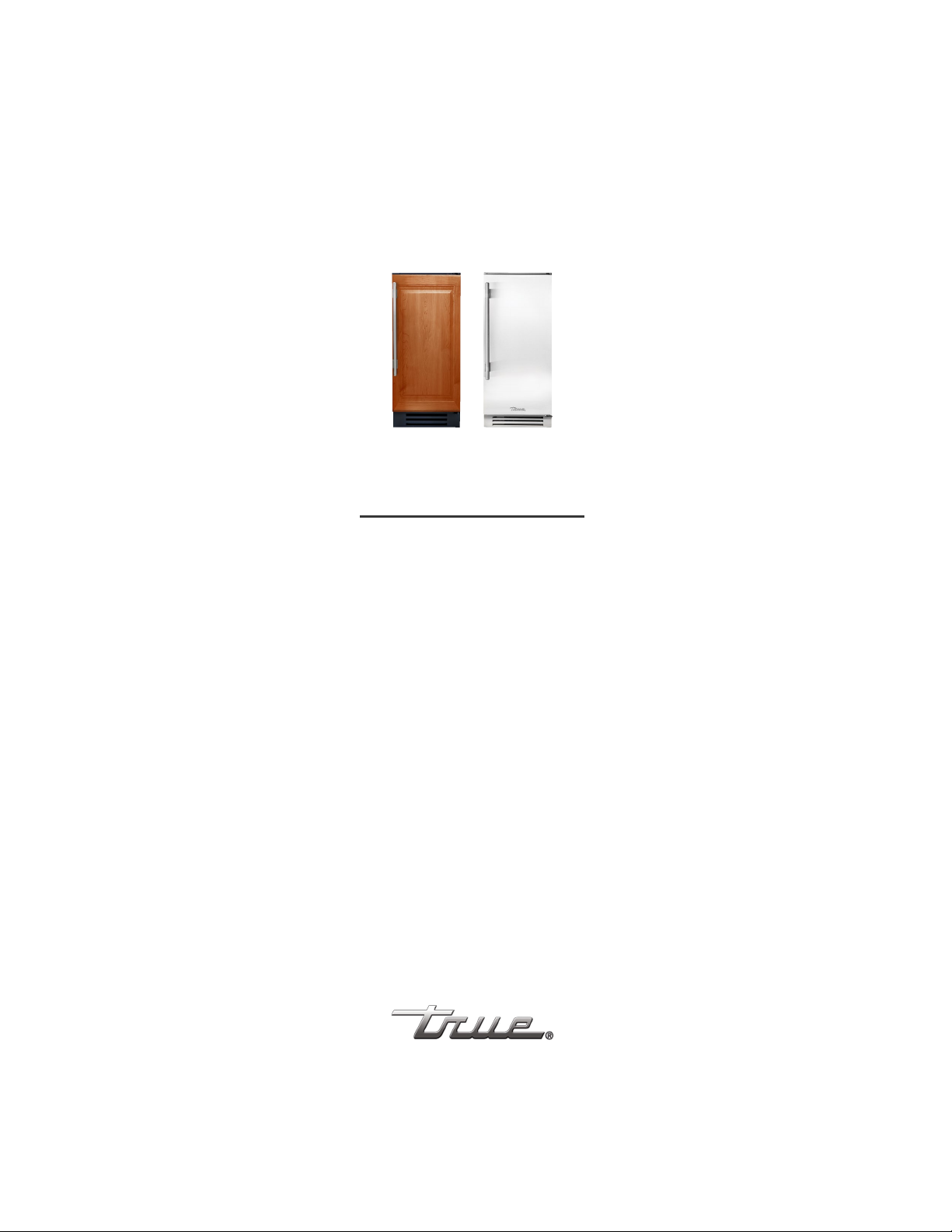
15 INCH CLEAR ICE MACHINE MODELS
INSTALLATION GUIDE AND USER’S MANUAL
®
Page 2
As a family-owned business, we believe in the importance of service,
so we’ve always made sure that good help isn’t hard to find, whether
that means providing design inspiration or product information. For 70
years, we’ve been pioneers in cold, but we’ve also been leaders in warm
customer service and support. We hope that this guide offers you what
you need for the True Residential
®
products in your customers’ (or your
own) homes. If you don’t see what you’re looking for, please contact True
customer service at 888-616-8783 or info@true-residential.com or you
may also visit our website at true-residential.com
Page 3

Commercial refrigeration refined for the home, envied in the industry,
and crafted—gorgeously—in America.
Page 4

C ON T E N T S
INSTALLATION CHECKLIST 1
15 INCH TRUE ICETM MACHINE MODELS 3
FEATURES OF THE TRUE ICETM MACHINE 6
OWNERSHIP 6
SAFETY PRECAUTIONS 6
PROPER DISPOSAL AND CFC DISPOSAL 7
WARNING & SAFETY LABELS 7
UNCRATING 8
ELECTRICAL SPECIFICATIONS 9
INSTALLATION SPECIFICATIONS 12-16
OVERLAY PANEL INSTALLATION 17-18
INSTALLING DOOR STOP 19
PLUMBING CONNECTIONS 19
LEVELING ICE MACHINE 20
WATER SUPPLY 20
DRAIN CONNECTION 21
WATER FILTER 22
POSITION THE UNIT 22
PUMPING HEIGHTS 23-24
DRAIN ALARM (DRN) 25
TRUE PRECISION CONTROL® OPERATION AND TRUE ICE™ MACHINE COMPONENTS 27
BEFORE OPERATING 28
ICE MAKING SEQUENCE 29
POWER AND BIN LIGHT 30
CUBE SIZE ADJUSTMENT 30
BIN THERMOSTAT / ICE LEVEL ADJUSTMENTS 31
BREAKER RESET 31
WATER QUALITY SETTING 31
GENERAL MAINTENANCE 34
WATER SHUTTERS, ICE CHUTE, AND PUMP CLEAN-OUT CAP 35
SPRAY BAR DISASSEMBLY 36
WATER FILTER REPLACEMENT AND REPLACEMENT PARTS 37
CONDENSER CLEANING INSTRUCTIONS 37
STAINLESS STEEL EQUIPMENT CARE AND CLEANING 38
DESCALING AND SANITIZING 38-39
EXTERIOR CLEAN, WINTERIZING AND RESTART INSTRUCTIONS 39
FREQUENTLY ASKED QUESTIONS 41
WARRANTY 42-43
Page 5

Page 6

INSTALLATION CHECKLIST
Use this checklist during installation to ensure that no part of the process has been overlooked.
Has an authorized True dealer or licensed installer inspected stainless steel surfaces for imperfection?
(Cosmetic defects are covered by a limited 30-day warranty)
Have all packaging materials and tape been removed?
Is the water temperature always between 40˚F (4˚C) and 100˚F (38˚C)?
Is the power cord plugged into a properly grounded three-prong outlet in accordance
with all applicable electrical codes?
Have the water supply and drain connections been made?
Has the ice machine drain line been routed into an open drain with no more than eight feet (2.4 m) of rise
and 100 feet (33 m) of run?
Is the unit leveled properly with all leveling legs making contact with the floor?
Has the door stop been installed? (If required)
Are panels attached securely and properly aligned? (Overlay cabinets only)
Has the machine been set for the local water quality?
Has the water filter been installed?
Is the water supply turned on?
Have the connections been checked for water leaks?
Is the machine turned on and working properly?
Have the first two batches of ice been discarded?
Does the machine shut off when ice is held against the thermostat tube?
Has the customer reviewed the unit’s operation in this manual?
Has the customer reviewed the schedule of maintenance of the machine?
15 INCH TRUE ICETM MACHINE INSTALL GUIDE
1
Page 7

2
TRUE RESIDENTIAL
®
Page 8
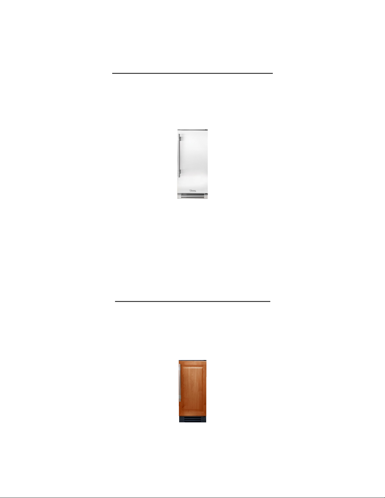
15 INCH STAINLESS STEEL
STAINLESS STEEL DOOR (SS)
TM
15 INCH TRUE
TUI-15-R/L-SS-B
ICE MACHINE
15 INCH OVERLAY PANEL
SOLID PANEL READY DOOR (OP)
TM
15 INCH TRUE
TUI-15-R/L-OP-B
ICE MACHINE
15 INCH TRUE ICETM MACHINE INSTALL GUIDE
3
Page 9

4
TRUE RESIDENTIAL
®
Page 10

FEATURES OF THE ICE MACHINE
OWNERSHIP
SAFETY PRECAUTIONS
5 - 9
PROPER DISPOSAL AND CFC DISPOSAL
WARNING & SAFETY LABELS
UNCRATING
ELECTRICAL SPECIFICATIONS
15 INCH TRUE ICETM MACHINE INSTALL GUIDE
5
Page 11

FEATURES OF THE TRUE™ ICE MACHINE
SAFETY PRECAUTIONS
• Produces up to 70 pounds of ultra-clear gourmet
ice cubes per day.
• Stores 28 pounds of ice cubes.
• Three-Character LED display tells you what your
machine is doing.
• Auto-clean sequence for walk-away cleaning
simplicity.
• Cleaning time remaining is shown on the display.
• Drain pump standard on all models.
• Built-in water filter insures that no parts are
exposed to unfiltered water.
• Fourteen-Color LED bin light.
• High quality ice scoop and built-in scoop holder
included.
• Automatic filter change reminder.
• UL approved for outdoor use.
• Industry-leading True Warranty on page 42.
• This ice machine must be properly installed
and located in accordance with the installation
instructions before it is used.
• Do not allow children to climb, stand or hang
on the ice machine. They could damage the ice
machine and seriously injure themselves.
• Do not store or use gasoline or other flammable
vapors and liquids in the vicinity of this or any
other appliance.
• Keep hands away from the “pinch point” areas and
gaps between the doors and cabinet. Small areas
are not necessarily safe.
• Unplug the ice machine before cleaning behind
the kickplate or making repairs.
• Setting power switch to OFF only removes power
from the refrigeration system, it does not remove
power from other circuits. To fully power-down the
machine it must be unplugged.
OWNERSHIP
TO INSURE THAT YOUR UNIT WORKS PROPERLY
FROM THE FIRST DAY, IT MUST BE INSTALLED
PROPERLY.
NOTE: WE HIGHLY RECOMMEND A TRAINED
INSTALLER, PLUMBER OR ELECTRICIAN INSTALL
YOUR TRUE RESIDENTIAL® ICE MACHINE. THE
COST OF A PROFESSIONAL INSTALLATION IS
MONEY WELL SPENT.
Before you start to install your True Residential® Ice
Machine, carefully inspect it for freight damage. If
damage is discovered, immediately file a claim with
the delivery freight carrier. True is not responsible for
damage incurred during shipment.
Any questions about the installation please
contact your True dealer or True Technical Service
Department at 844-746-9423. Please have your
model and serial numbers available when you call our
Service Department.
NOTE: WE STRONGLY RECOMMEND
THAT ANY SERVICING BE PERFORMED
BY A QUALIFIED INDIVIDUAL.
WARNING: PROPER INSTALLATION REQUIRES
CONNECTION TO THE WATER SUPPLY, A DRAIN
AND A DEDICATED ELECTRICAL CIRCUIT. THESE
CONNECTIONS ARE THE RESPONSIBILITIES OF
THE INSTALLER. IMPROPER CONNECTIONS CAN
RESULT IN PERSONAL INJURY, PROPERTY DAMAGE
AND IMPROPER OPERATION. THE ICE MACHINE
MUST BE INSTALLED ACCORDING TO ALL
APPLICABLE NATIONAL, STATE AND LOCAL
CODES AND REGULATIONS.
6
TRUE RESIDENTIAL
®
Page 12
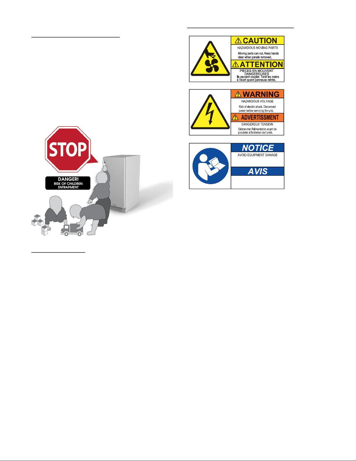
PROPER DISPOSAL OF
THE OLD ICE MACHINE
Child entrapment and suffocation are not problems
of the past. Junked or abandoned ice machines are
still dangerous, even if they will sit for “just a few
days.” If you are getting rid of your old ice machine,
please follow the instructions below to help prevent
accidents.
BEFORE YOU THROW AWAY YOUR OLD ICE MACHINE, TAKE
OFF THE DOORS.
WARNING & SAFETY LABELS
CAUTION:
Located on the
back of the unit.
WARNING:
Located on the
back of the unit.
NOTICE:
Do not operate without a lter installed. Replace
lter annually. Reset “FLT” reminder by holding
CLEAN and LIGHT buttons for 5 seconds.
No opere sin el ltro instalado. Reemplace el
ltro una vez al año. Reinicie el recordatorio
“FLT” manteniendo presionados los botones
CLEAN y LIGHT por 5 segundos.
Behind front
door next to
water filter.
CFC DISPOSAL
Your old ice machine may have a cooling system that
used CFCs (chlorofluorocarbons). CFCs are believed
to harm stratospheric ozone. If you are throwing away
your old ice machines, make sure the CFC refrigerant
is removed for proper disposal by a qualified service.
If you intentionally release this CFC refrigerant you
can be subject to fines and imprisonment under
provisions of the environment legislation.
15 INCH TRUE ICETM MACHINE INSTALL GUIDE
7
Page 13
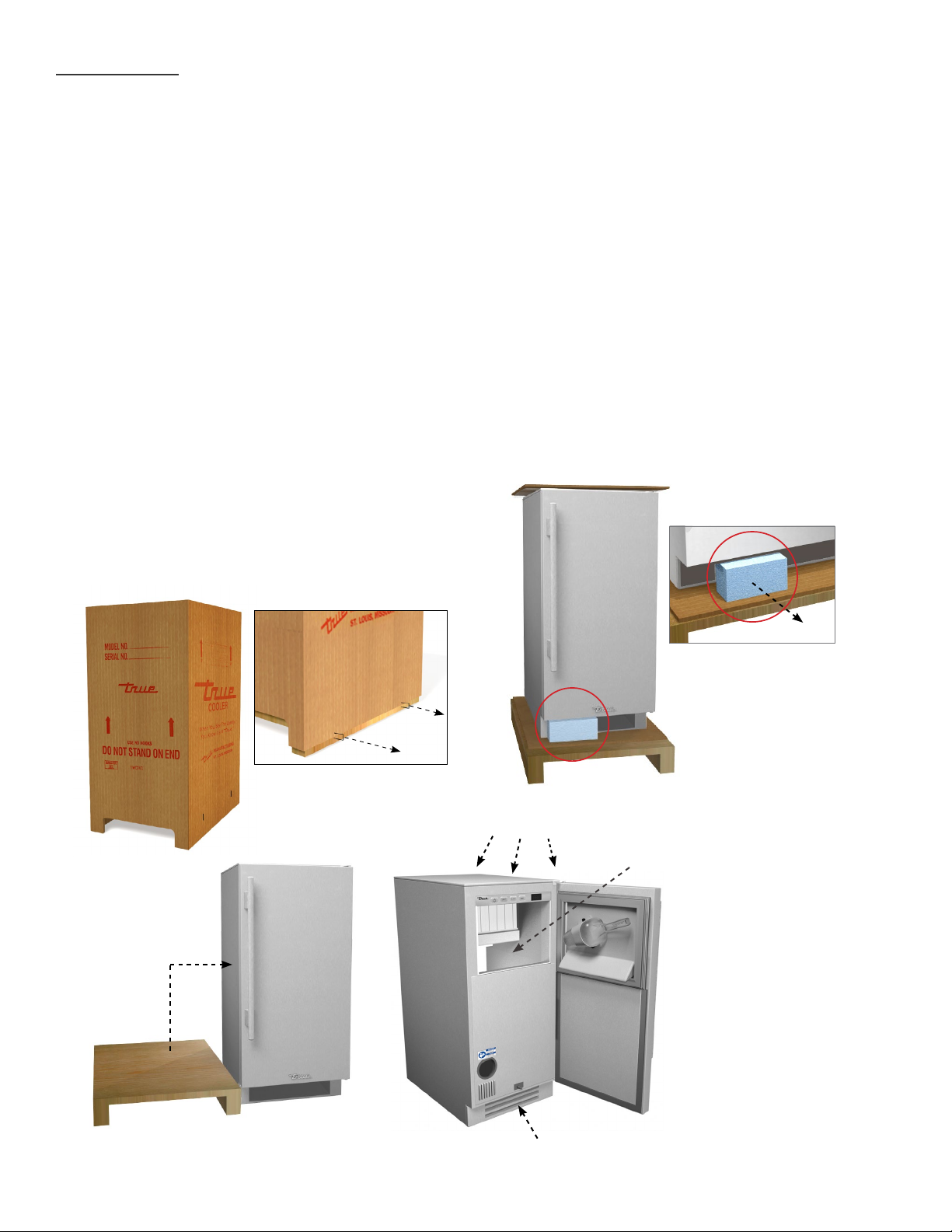
UNCRATING
Required Tools:
• Cutting utensil (utility knife)
• Hammer
• Crowbar
• Phillips screwdriver
INSPECT FOR CONCEALED DAMAGE. AGAIN,
IMMEDIATELY FILE A CLAIM WITH THE FREIGHT
CARRIER IF THERE IS DAMAGE.
The following procedure is recommended for
uncrating the unit:
Move your unit as close to the final location as
possible before removing the wooden skid.
A. Remove staples securing cardboard box to the
wooden skid. Then discard any outer packaging
(cardboard, clear plastic). Cut off all strapping.
B. IMPORTANT: Remove Styrofoam block before
removing ice machine from pallet.
C. Remove skid by carefully lifting the ice machine
off and place skid aside.
D. Open the unit and remove any packing material.
Styrofoam, tape, and any other material used for
shipping purposes.
E. Remove kickplate located inside ice bin. The
kickplate attaches to the front of the ice machine
with magnets.
B
A
PACKING MATERIAL
D
C
REMOVE KICKPLATE
E
FROM ICE BIN
8
TRUE RESIDENTIAL
KICKPLATE INSTALLED
®
Page 14

ELECTRICAL SPECIFICATIONS
WARNING: THIS APPLIANCE MUST BE PROPERLY
GROUNDED. DO NOT, UNDER ANY CIRCUMSTANCES,
CUT OR REMOVE THE THIRD (GROUND) PRONG
FROM THE POWER CORD. FOR PERSONAL SAFETY,
THIS APPLIANCE MUST BE PROPERLY GROUNDED.
The electrical outlet must be within three feet of
the center of the back wall of the ice maker’s final
location. Outlet must be flush with wall and comply
with local electrical codes.
Before your new unit is connected to a power supply,
check the incoming voltage with a volt meter. If
anything less than 100% of the rated voltage for
operation is noted, correct immediately.
The power cord of this appliance is equipped with
a three-prong (grounding) plug which mates with
a standard three-prong (grounding) wall outlet to
minimize the possibility of electric shock hazard from
this appliance. A 115V AC, 60 Hz, 15 amp circuit
breaker and electrical supply are required.
Have the wall outlet and circuit checked by a qualified
electrician to make sure the outlet is properly
grounded.
If the outlet is a standard
two-prong outlet, it is your personal
responsibility and obligation to have
it replaced with the properly
grounded three-prong wall outlet.
Do not use an extension cord or
two-prong adaptor. Electrical ground
is required on this appliance.
The unit should always be plugged into its own
individual electrical outlet which has a voltage rating
that matches the rating plate. This provides the best
performance and also prevents overloading house
wiring circuits which could cause a fire hazard from
overheated wires. Never unplug your ice machine by
pulling on the power cord. Always grip plug firmly and
pull straight out from the outlet.
Repair or replace immediately all power cords that
have become frayed or otherwise damaged. Do not
use a cord that shows cracks or abrasion damage
along its length or at either end. When moving the ice
machine away from the wall, be careful not to roll over
or damage the power cord.
The unit is approved by UL for outdoor installation.
15 INCH TRUE ICETM MACHINE INSTALL GUIDE
9
Page 15

10
TRUE RESIDENTIAL
®
Page 16

INSTALLATION SPECIFICATIONS
OVERLAY PANEL INSTALLATION
INSTALLING DOOR STOP
PLUMBING CONNECTIONS
11 - 25
LEVELING ICE MACHINE
WATER SUPPLY
DRAIN CONNECTION
WATER FILTER
PUMPING HEIGHTS
DRAIN ALARM (DRN)
15 INCH TRUE ICETM MACHINE INSTALL GUIDE
11
Page 17
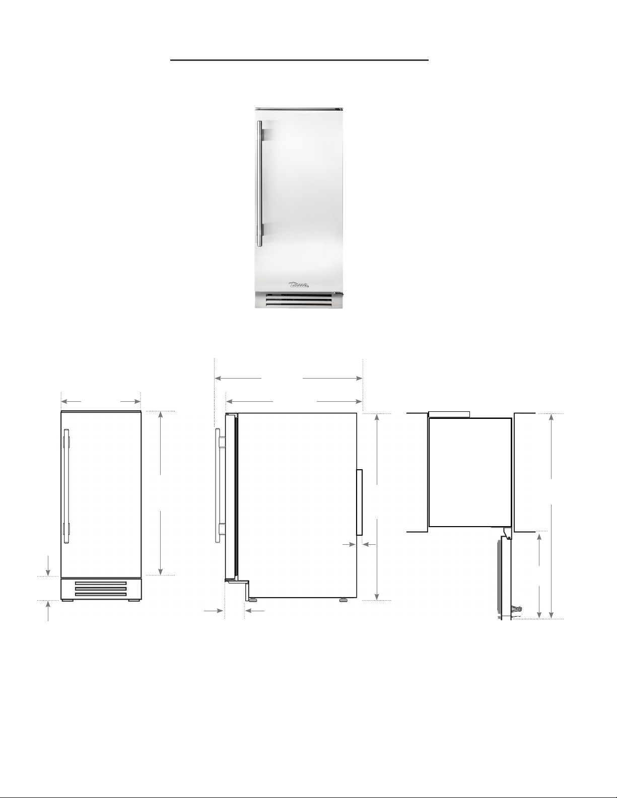
15 INCH STAINLESS STEEL
ICE MACHINE TUI-15-R/L-SS-B
A
7/8
"
14
B
¾
"
25
7/8
"
23
FRONT
FRONT
VIEW
VIEW
OF
30
ICE MACHINE
3/16
"
4
11/16
"
3
SIDE
SIDE VIEW
VIEW
OF
ICE MACHINE
34
½
"
1
C
TOP VIEW
TOP
OF
VIEW
ICE MACHINE
¼
"
SURROUNDING CABINETRY
16
7/8
"
37
SURROUNDING CABINETRY
¼
"
12
TRUE RESIDENTIAL
Dimensions may vary by ± 1/8"
®
Page 18
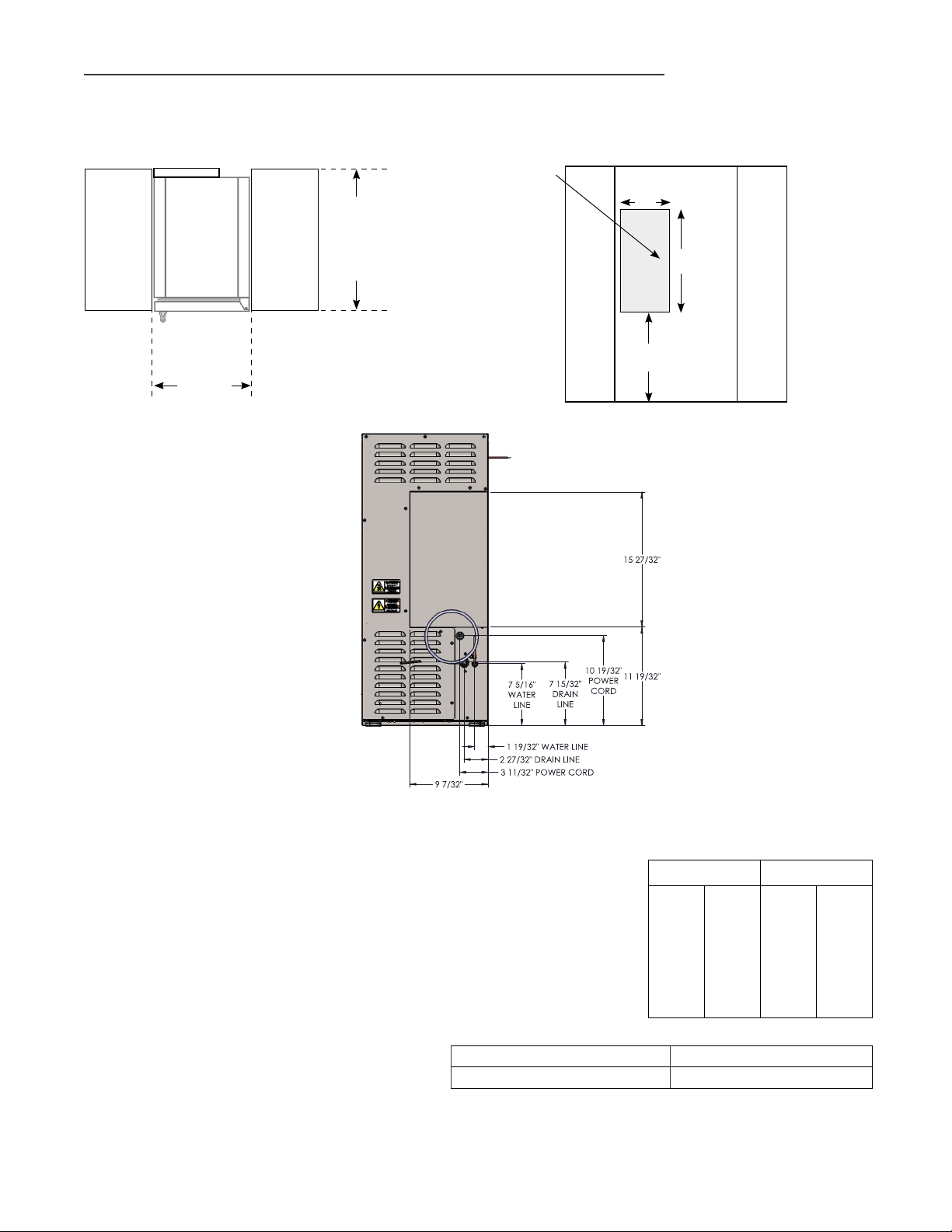
INSTALLATION SPECIFICATIONS - STAINLESS SOLID DOOR
True’s Stainless Solid Door units are designed to be inserted into a cabinet opening or free standing.
Below are recommended minimum dimensions for rough opening.
Avoid running
TOP VIEW
OF UNIT
BETWEEN
CABINETRY
ROUGH
OPENING
WIDTH
15"(min.)
ROUGH
OPENING
DEPTH
24" (min.)
wires or
plumbing in
this area.
SURROUNDING CABINETRY
BACK VIEW
OF
ICE MACHINE
9"
11½"
16"
SURROUNDING CABINETRY
FRONT
VIEW OF
CABINETRY
OPENING
CAUTION: DO NOT ALLOW THE ICE MACHINE
TO BE EXPOSED TO TEMPERATURES
BELOW 32°F (0°C) AS THIS WILL CAUSE
ANY WATER IN THE MACHINE TO FREEZE.
FAILURES CAUSED BY EXPOSURE TO
FREEZING TEMPERATURES ARE NOT
COVERED BY THE WARRANTY.
ALLOWABLE TEMPERATURES AND PRESSURES
MINIMUM MAXIMUM
AIR TEMPERATURE 40˚ F 4˚ C 100˚ F 38˚ C
WATER TEMPERATURE 40˚ F 4˚ C 100˚ F 38˚ C
WATER PRESSURE
* Max Ice Production 70 lbs/day
** Rated Ice Production 57 lbs/day
* Performance Rated at 70°F air / 50°F water / 30 psig water pressure.
Performance Rated at 90°F air / 70°F water / 30 psig water pressure.
**
15 INCH TRUE ICETM MACHINE INSTALL GUIDE
20
PSI
1.4
BAR
80
PSI
5.5
BAR
13
Page 19
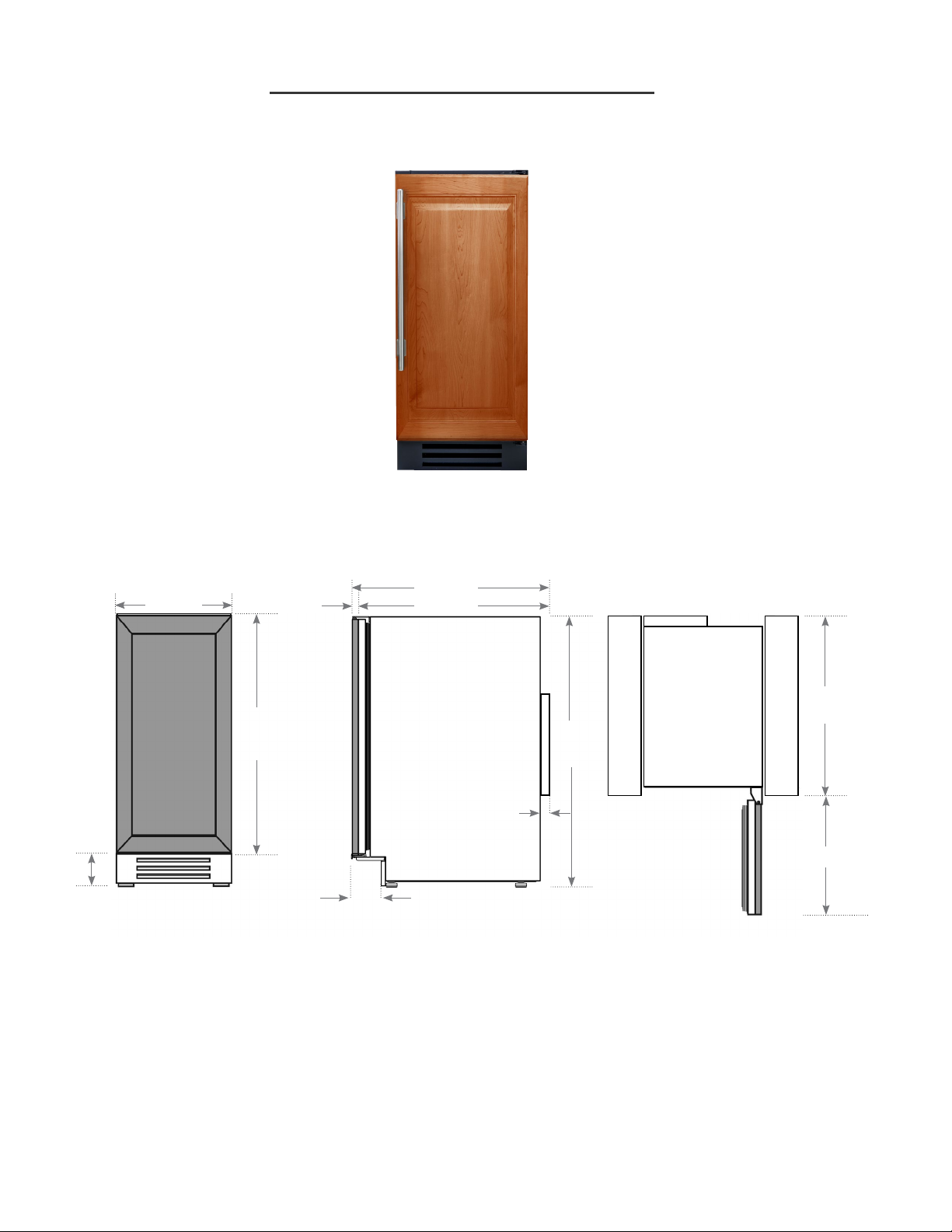
15 INCH OVERLAY PANEL
ICE MACHINE TUI-15-R/L-OP-B
A
7/8
"
14
B
7/8
"
¾
"
23
23
1/8
"
C
FRONT
VIEW
OF
ICE
29
SIDE VIEW
OF
¾
"
ICE MACHINE
34
¼
"
TOP VIEW
OF
ICE MACHINE
21
5/8
"
MACHINE
SURROUNDING CABINETRY
½
"
1
1/8
"
4
*3
¾
"
SURROUNDING CABINETRY
¼
"
16
Dimensions may vary by ± 1/8"
*Including 3/4" thick panel (provided by others)
NOTE: UNIT IS SHOWN WITH OPTIONAL PANEL / HANDLE PROVIDED BY OTHERS.
14
TRUE RESIDENTIAL
®
Page 20
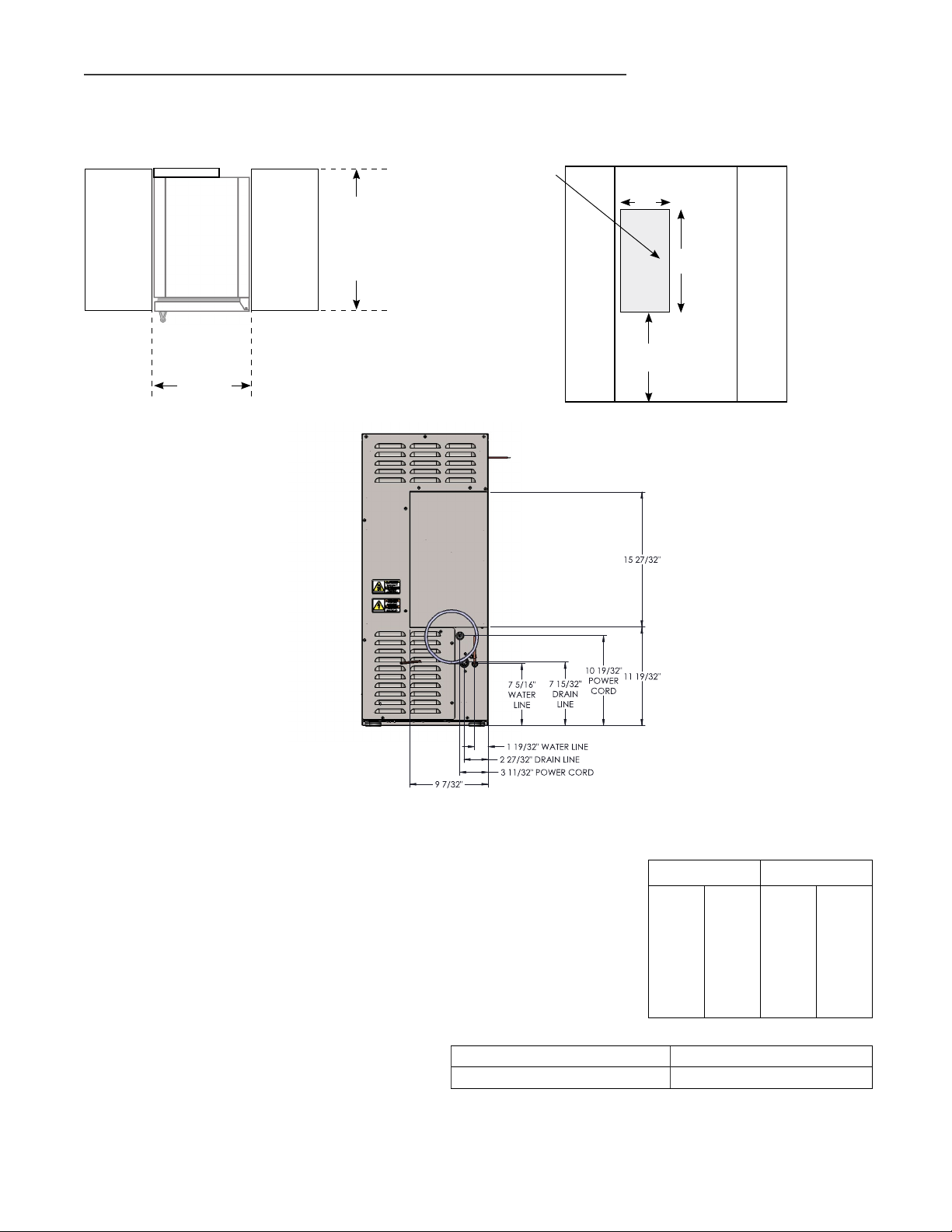
INSTALLATION SPECIFICATIONS - SOLID PANEL READY
True’s Solid Panel Ready Door units are designed to be inserted into a cabinet opening or free standing.
Below are recommended minimum dimensions for rough opening.
Avoid running
TOP VIEW
OF UNIT
BETWEEN
CABINETRY
ROUGH
OPENING
WIDTH
15"(min.)
ROUGH
OPENING
DEPTH
24" (min.)
wires or
plumbing in
this area.
SURROUNDING CABINETRY
BACK VIEW
OF
ICE MACHINE
9"
11½"
16"
FRONT
VIEW OF
CABINETRY
OPENING
SURROUNDING CABINETRY
CAUTION: DO NOT ALLOW THE ICE MACHINE
TO BE EXPOSED TO TEMPERATURES
BELOW 32°F (0°C) AS THIS WILL CAUSE
ANY WATER IN THE MACHINE TO FREEZE.
FAILURES CAUSED BY EXPOSURE TO
FREEZING TEMPERATURES ARE NOT
COVERED BY THE WARRANTY.
ALLOWABLE TEMPERATURES AND PRESSURES
MINIMUM MAXIMUM
AIR TEMPERATURE 40˚ F 4˚ C 100˚ F 38˚ C
WATER TEMPERATURE 40˚ F 4˚ C 100˚ F 38˚ C
WATER PRESSURE
* Max Ice Production 70 lbs/day
** Rated Ice Production 57 lbs/day
* Performance Rated at 70°F air / 50°F water / 30 psig water pressure.
Performance Rated at 90°F air / 70°F water / 30 psig water pressure.
**
15 INCH TRUE ICETM MACHINE INSTALL GUIDE
20
PSI
1.4
BAR
80
PSI
5.5
BAR
15
Page 21
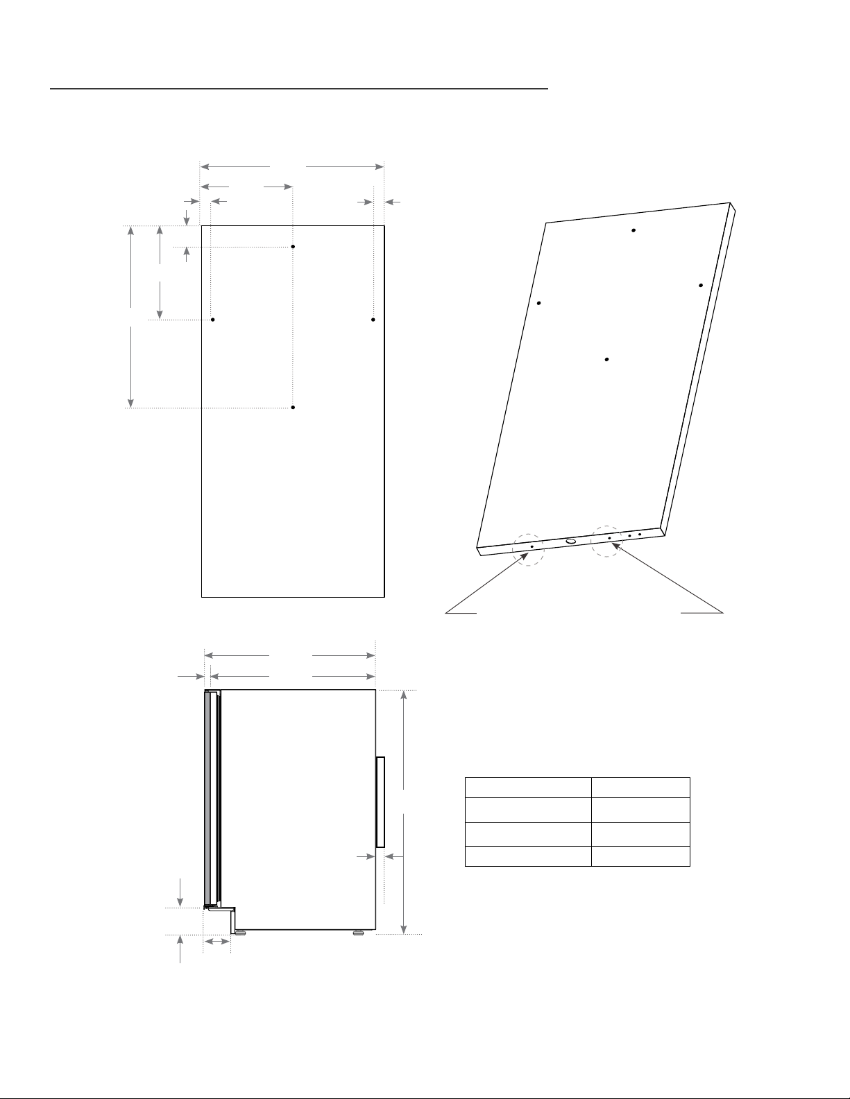
INSTALLATION SPECIFICATIONS - SOLID PANEL READY
CUSTOM PANEL INSTALLATION
5/8
"
SOLID DOOR
29/32
½
"
7
5/32
"
13
1
"
21/32
7
"
14
5/16
"
BACK VIEW OF SOLID
OVERLAY PANEL
29/32
"
PANEL BRACKETS (988675) MOUNT
IN THESE TWO LOCATIONS TO
HOLD BOTTOM OF OVERLAY PANEL
7/8
"
23
¾
"
23
1/8
"
SOLID DOOR PANEL DIMENSIONS
SIDE
VIEW
34
¼
"
Door Panel Width 14 5/8
Door Panel Height 29 23/32
Door Panel Depth 3/4" max
½
"
1
1/8
"
4
¾
*3
"
Door Panel Weight 10 lb. max.
"
"
16
TRUE RESIDENTIAL
*Including 3/4" thick panel (provided by others)
®
Page 22
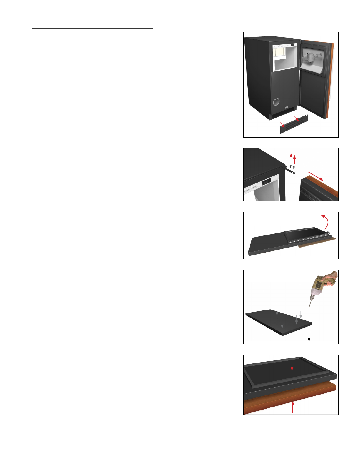
OVERLAY PANEL INSTALLATION
Required Tools:
•
Phillips Screwdriver
•
3/ 8" Wrench
•
1/8" Drill Bit
•
Three (3) Screws #6
SEE PAGE 16 FOR OVERLAY PANEL DIMENSIONS
BEFORE INSTALLING.
FOR EASY OVERLAY INSTALLATION, ICE MACHINE
DOOR REMOVAL IS REQUIRED.
1. Open front door and pull kickplate forward
to remove.
2. To remove door, back out two bottom hinge
screws with a 3/8" wrench. Secure door while
removing screws. Remove two Phillips screws
from the top hinge. Save all these screws for later
reinstall.
1
2
Remove screws
from top and
bottom hinge
3. Lay door on a safe solid surface. Lay cardboard
or other safe material down before working on
th e door.
4. Remove door gasket from the inside of the door
frame. Place gasket to the side for later reinstall.
5. There are pre-marked areas on the front of the
door. Drill these pre-marked holes with 1/8" drill
bit. Make sure to drill all the way through the
do o r.
NOTE: IF HANDLE IS BEING USED ON OVERLAY,
INSTALL IT BEFORE STEP 8 (SEE IMAGE A ON
PAGE 22). FOR BEST INSTALLATION, SCREWS
ATTACHING HANDLE SHOULD BE RECESSED.
6. It is recommended to clamp the door front on
top of the overlay before drilling pilot holes and
installing anchor screws. The clamp ensures the
overlay panel and door stay aligned with each
other while installing. Once panel is clamped in
place, pilot holes may be drilled into the panel
from the rear side of the door. Mark to only drill
1/2" into rear side of door.
3 & 4
5
6
15 INCH TRUE ICETM MACHINE INSTALL GUIDE
17
Page 23
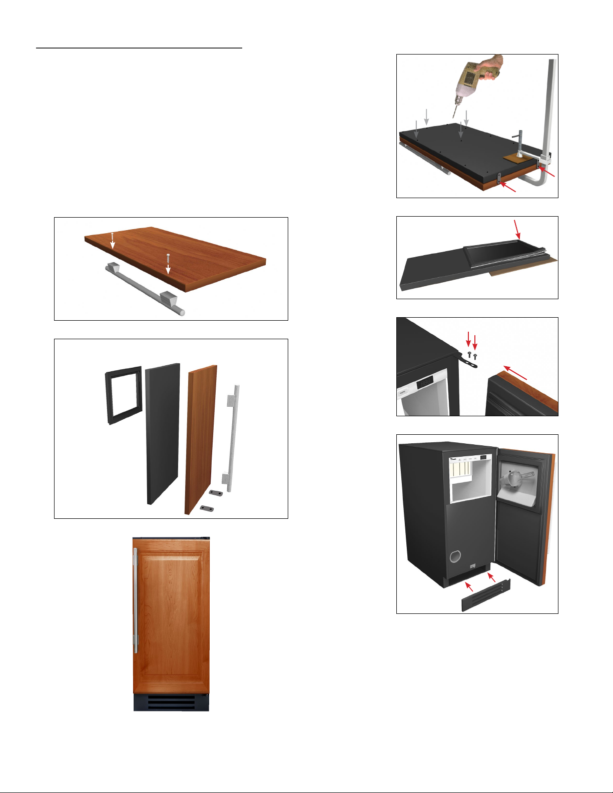
OVERLAY PANEL INSTALLATION
7. O nce all holes are pre-drilled, use the appropriate
specified screws to secure the overlay panel onto
the front of the ice machine door. Be sure to
attach the bottom of the panel to the door using
the brackets.
8. Reinstall all components in reverse order. Door
gasket snaps back into place. Overlay panel and
door stay aligned with each other while installing.
IMAGE A
Door Layers - General View
DOOR
OVERLAY PANEL
7
8
Reinstall screws
on top and
bottom hinge
GASKET
HANDLE
18
TRUE RESIDENTIAL
OVERLAY PANEL
®
Page 24
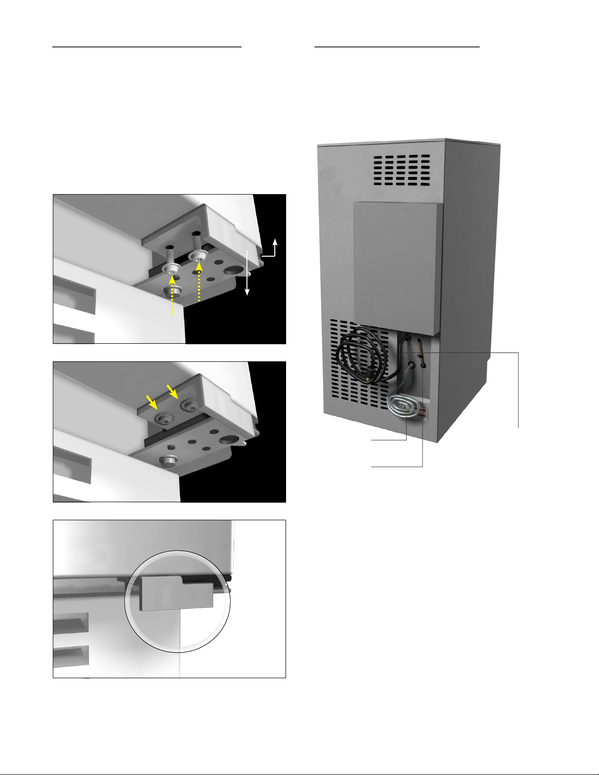
INSTALLING THE DOOR STOP
PLUMBING CONNECTIONS
All units are provided with an optional door stop.
When installed, the door stop will restrict the door
from opening past approximately 120º to prevent
damage to surrounding cabinetry. To install the
door stop, use the two screws provided and secure
the bracket to the bottom of the door on the same
side as the hinge.
Hinge
Door stop
The ice machine must be installed with adequate
clearance for water and drain connections at the rear
of the unit. Prepare the water supply line and drain
connections before installing your ice machine.
Cabinet door
Kickplate
Door stop
Installed
DRAIN HOSE
WATER IN LET
POWER CORD
15 INCH TRUE ICETM MACHINE INSTALL GUIDE
19
Page 25
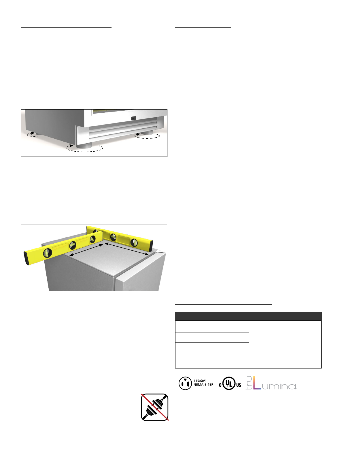
LEVELING ICE MACHINE
WATER SUPPLY
1. Set unit in its final location. Be sure there is
adequate ventilation in your room.
2. Proper leveling of your True unit is critical to
operating success. Effective drainage and door
operation will be affected by leveling. Adjust leg
levelers on the front and back of the cabinet if
needed to level the unit.
3. The unit should be leveled from the top of the unit
front to back and side to side with a level. If the
ice machine is not level adjust the stainless steel
leg levelers. The leg levelers can be adjusted by
turning to reach the desired leveling height as
shown in the illustration above.
Locate the water supply.
The water supply line should be connected to the
house supply with an easily accessible shut-off valve
between the water supply and the ice machine. A
reverse osmosis system can be used, provided there
is constant water pressure of 20 psi (1.4 bar) to 80
psi (5.5 bar) supplied to the ice machine at all times.
A copper line is not recommended for this application.
CAUTION: WATER PRESSURE MUST BE BETWEEN
20 PSI (1.4 BAR) AND 80 PSI (5.5 BAR).
A REVERSE OSMOSIS SYSTEM CAN BE USED,
PROVIDED THE WATER PRESSURE STAYS
WITHIN THE REQUIRED RANGE ABOVE. IF THE
WATER PRESSURE EXCEEDS THE MAXIMUM
PRESSURE, INSTALL A WATER PRESSURE
REGULATOR.
A cold water supply line must be supplied to the ice
machine. Use 1/4" OD copper, braided stainless steel
or PEX tubing and compression fittings (not included).
The incoming water temperature must remain between
40°F (4°C) and 100°F (38°C).
4. Free plug and cord from back of ice machine
(do not plug in).
5. The unit should be placed close enough to
the electrical supply so that extension cords
are never used.
6. Once installed in final location, attach kickplate to
the magnets on the front of the unit.
WARNING: COMPRESSOR WARRANTIES ARE VOID
IF THE UNIT IS MORE THAN SEVEN FEET (2.1 M)
FROM PLUG-IN CONNECTION OR IF AN
EXTENSION CORD IS USED.
Do not connect the ice machine to a hot water supply.
Be sure all hot water restrictors installed for other
equipment are working, such as check valves on sink
faucets, dishwashers, etc.
Insulate the water supply line to prevent condensation.
ELECTRICAL & PLUMBING
ELECTRICAL PLUMBING
Voltage: 115/60/1
Min Circuit Ampacity (amps): 15
Power Cord Length: 8'
Annual kWh Consumption:
9.5 kwh/100 lb
Water Supply: 1/4 inch OD copper,
braided stainless steel or PEX
tubing and compression fittings (not
included)
Drain Pump Connection: Supplied
with 8 ft. of 3/ 8 inch OD plastic
tubing
20
TRUE RESIDENTIAL
®
Page 26
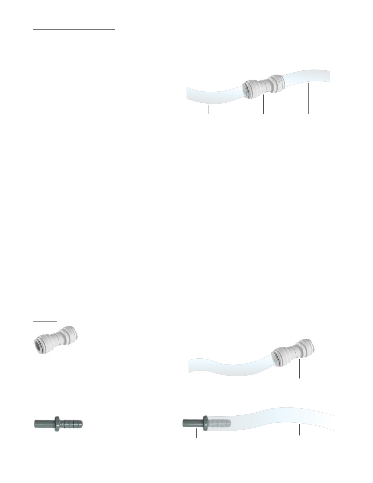
DRAIN CONNECTION
OPTION 1
CAUTION: NO MATTER WHAT DRAIN
OPTION IS USED WE SUGGEST
THOROUGHLY INSPECTING ALL
CONNECTIONS AFTER INSTALLED TO
ASSURE THERE ARE NO LEAKS.
The True Ice™ machine has a built-in drain pump
that will pump water up to a drain point, such as
a sink.
• Eight feet of 3/8" O.D. plastic tubing is
supplied with the ice machine.
• The drain pump has a maximum rise of 8
feet (2.4 m) and a maximum run of 100 feet
(33 m).
If higher than 8 feet, an optional pump may
be required.
• The floor drain must be large enough to
accommodate drainage from all drain lines.
• The drain pump discharge line must terminate
at an open site drain.
Extending current 3/8” O.D. drain line.
• To do this install, use provided 3/8” O.D.
union adapter.
3/8” O.D. HOSE
(8 ft. provided)
3/8” union
adapter
(Provided)
3/8” O.D. HOSE
(Additional not
provided)
CAUTION: THIS MUST NOT BE EXTENDED
MORE THEN 100 FOOT RUN OR HIGHER
THAN AN 8 FOOT RISE.
OPTION 2
Adapting provided 8 foot 3/8” O.D. drain line to
1/2” I.D. / 5/8” O.D. drain line.
• To do this connect 3/8” union adapter to
current drain line. (Make sure drain line is cut
at perfect 90º degree angle before installing
union adapter).
OTHER DRAIN CONNECTIONS
To accommodate your installation we have also
provided a few pieces which allow for different
drain configurations:
Fitting 1 - 3/8” to 3/8” union adapter
CAUTION: FOR CONNECTION TO WORK
AS DESIGNED, TUBING SHOULD BE
CUT AT PERFECT 90º DEGREE ANGLE
BEFORE INSTALLING ON UNION ADAPTER.
Fitting 2 - 3/8” O.D. to 1/2” ID barb fitting.
• Push smooth end of barb fitting into the
3/8” O.D. union adapter & then connect
1/2” I.D. / 5/8” O.D. to barbed end of plastic
fitting securely.
NOTE: 1/2” I.D. / 5/8” O.D. TUBING NOT
PROVIDED.
CAUTION: IF THIS OPTION IS CHOSEN, THE
MAXIUM PUMP RISE IS 4 FOOT.
3/8” O.D. HOSE
(Provided)
3/8” push to
1/2” I.D. barb
(Provided)
3/8” union
adapter
(Provided)
5/8” O.D. HOSE
(Not provided)
15 INCH TRUE ICETM MACHINE INSTALL GUIDE
21
Page 27

WATER FILTER
The built-in water filter is designed to filter sediment,
remove unpleasant taste and odor and inhibit scale.
The life expectancy of the filter is twelve months for low
scale water and six months if the water has a high level
of scale. The ice machine monitors how long the filter
has been in operation and will display “FLT” when the
filter needs to be replaced. See water filter replacement
instructions on page 37.
Replacement water filters are available through your
True dealer.
CAUTION: INSTALL THE WATER FILTER BEFORE
TURNING ON THE WATER SUPPLY TO THE ICE
MACHINE.
CAUTION: DO NOT ALLOW THE ICE MACHINE TO
BE EXPOSED TO TEMPERATURES BELOW 32°F
(0°C) AS THIS WILL CAUSE ANY WATER IN THE
MACHINE TO FREEZE. FAILURES CAUSED BY
EXPOSURE TO FREEZING TEMPERATURES ARE
NOT COVERED BY THE WARRANTY.
POSITION THE UNIT
Once the unit has been leveled and connected to a
drain, the water supply can be connected and turned
on. The unit can then be plugged in and energized.
Once these steps are complete, slide the unit into its
final desired position, presumably inside the cabinetry.
You should then proceed to the “BEFORE OPERATING”
step on page 25.
22
TRUE RESIDENTIAL
®
Page 28
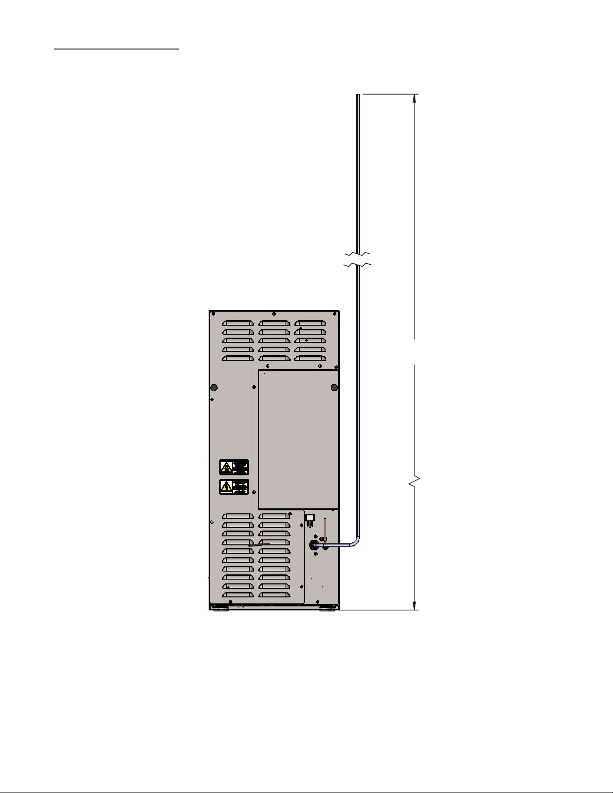
(8FT MAX)
WITH 3/8" O.D. HOSE
PUMPING HEIGHTS
STANDARD PUMP
96"
15 INCH TRUE ICETM MACHINE INSTALL GUIDE
23
Page 29
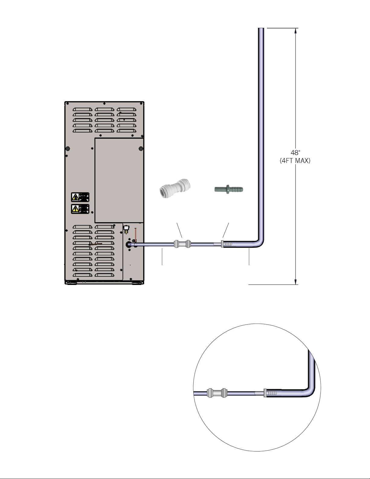
3/8” union
adapter
(Provided)
3/8” push to
1/2” I.D. barb
(Provided)
3/8” O.D. HOSE
(Provided)
STANDARD PUMP WITH
3/8" O.D. HOSE TO 5/8” O.D. HOSE
5/8” O.D. HOSE
(Not provided)
24
TRUE RESIDENTIAL
®
Page 30

DRAIN ALARM (DRN)
• The control will automatically signal and shut off
the water supply in the event of a drain failure.
• If a clogged drain clears the display will read
“DRN -OFF”.
CAUTION: ADHERE TO LOCAL AND STATE
PLUMBING CODES.
DO NOT EXCEED THE MAXIMUM PLUMBING
HEIGHTS FOR THE GIVEN SETUP. THE DRAIN
ALARM IS INITIATED BY THE CONTROL
BOARD IN THE EVENT OF IMPROPER
DRAINAGE.
VERIFY THE ICE MAKER DRAINS THROUGH
TWO CYCLES WITHOUT ANY ALARM DURING
INSTALLATION.
15 INCH TRUE ICETM MACHINE INSTALL GUIDE
25
Page 31

26
TRUE RESIDENTIAL
®
Page 32

TRUE PRECISION CONTROL® OPERATION AND
TRUE ICE™ MACHINE COMPONENTS
BEFORE OPERATING
POWER AND BIN LIGHT
27- 31
ICE MAKING SEQUENCE AND CUBE SIZE ADJUSTMENT
BIN THERMOSTAT / ICE LEVEL ADJUSTMENTS
BREAKER RESET
WATER QUALITY SETTING
15 INCH TRUE ICETM MACHINE INSTALL GUIDE
27
Page 33
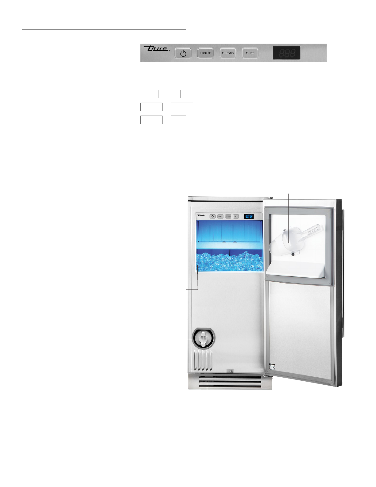
TRUE PRECISION CONTROL® OPERATION
1. Power Button
2. Bin Light
3. Initiate Cleaning Sequence
4. Adjust Cube Size
5. Display
ADDITIONAL CONTROL FEATURES:
Press
LIGHT
1 2 3 4 5
to change bin light color. See instructions on page 30.
CLEAN
CLEAN
“HSC” (High Scale) settings for incoming water.
TRUE ICE
ICE MACHINE DISPLAYS:
• OFF – Machine is off (unplug unit to
remove power to all components)
• ICE – Making ice
• HAr – Harvesting ice
• FUL – Bin is full
• FLT – Replace water filter
• BIg = 1, 2, 3, 4, 5 – Cube size setting
“1” = smallest, “5” = largest
• CLn – Cleaning Sequence
• Add – Add cleaning chemicals
(during cleaning sequence)
• Er1 – Failure of thermistor 1
• Er2 – Failure of thermistor 2
• drn – Drain pump failure
• Hot / 1* – Ambient too hot
• Hot / 2* – System too hot
• Cld / 1* – Ambient too cold
• Cld / 2* – System too cold
• LSC – Machine is set for low-scale water
• HSC – Machine is set for high-scale water
LIGHT
+
SIZE
+
™
MACHINE COMPONENTS
SERIAL
NUMBER
WATER
FILTE R
= Reset “FLT” (Filter Replacement Reminder).
= Toggle between the “LSC” (Low Scale) and
REMOVABLE KICKPLATE
FOR EASY CLEANING
ICE SCOOP AND
SCOOP HOLDER
* Display will alternate between messages. For
example, the display will show “Hot” then
“1”, continuing to alternate back and forth.
28
TRUE RESIDENTIAL
®
Page 34

BEFORE OPERATING
ICE MAKING SEQUENCE
To insure ice quality, please clean and sanitize
this machine prior to first use. To ensure proper
operation, follow the installation checklist at the
front of this manual.
NOTE: COSTS ASSOCIATED WITH ADJUSTMENTS,
CLEANING AND SANITIZING PROCEDURES
IN THIS GUIDE ARE NOT COVERED BY THE
WARRANTY.
WARNING: DO NOT USE THE ICE MACHINE TO
STORE ANYTHING OTHER THAN ICE.
WARNING: DO NOT OPERATE EQUIPMENT THAT
HAS BEEN MISUSED, NEGLECTED, DAMAGED,
ALTERED OR MODIFIED IN ANY WAY.
Your True Ice™ machine will produce one batch
of ice (24 cubes) roughly every 30 minutes. The
following steps occur during ice making:
HARVEST / FILL – The ice machine always begins
in the harvest mode. Display will read “HAr.” During
harvest all the ice cubes are melted free from the
evaporator. The ice machine does this by warming
up the evaporator with warm refrigerant. During
harvest the ice machine will also fill with water and
drain off any excess/residual ice making water. At
start up the harvest will last two minutes.
ICE MAKING – During ice making the display will
read “ICE.” Water is sprayed into the inverted ice
cups while the evaporator is cooled. This causes
ultra-clear ice cubes to form inside each ice cup.
The compressor, condenser fan and water pump
all operate during this mode. The ice machine
automatically adjusts the freeze time based on the
ambient air temperature.
FULL BIN – The ice machine shuts off automatically
when the bin is full of ice. A full bin is detected
when ice touches the bin thermostat tube. The
machine will come back on when ice is no longer in
contact with the thermostat tube.
15 INCH TRUE ICETM MACHINE INSTALL GUIDE
29
Page 35

POWER
SIZE
CUBE SIZE ADJUSTMENT
• Press the power button once to begin ice
making operation. Press the button a second
time to turn the ice machine off.
• When unit is plugged in, the control board
goes through a sequence of checks to verify all
sensors are working properly.
• The drain system is energized when power is
supplied to the unit. It automatically turns on
when it senses water in the drain tube.
• Display will show “OFF” until the power button
is pressed.
• If the unit powers the drain pump but the drain
remains clogged for five minutes, the display will
show “drn” and cut power to the unit.
• If unit is too cold (below 50˚F), too hot, or
if the temperature probe is unplugged or
has failed, the unit shuts down and displays
an error message.
Pressing the
button repeatedly allows you to
toggle between the available cubes sizes.
There are five cube sizes possible, where
“1” = smallest, “5” = largest.
NOTE: CUBE SIZE VARIATION IS RELATIVELY SMALL.
WHEN SET TO “1”, THE CUBES WILL BE HOLLOW, LIKE
A THIMBLE OR SHOT GLASS. WHEN SET TO “5”, THE
CUBES WILL BE SOLID. ALWAYS LET THE MACHINE
MAKE TWO BATCHES OF ICE BEFORE RESETTING THE
THICKNESS.
BIN LIGHT
Use the
•
PRESS THE
•
HOLD THE
LIGHT
button as follows:
LIGHT
BUTTON REPEATEDLY TO
CYCLE THROUGH THE 14 PRESET DESIGNER
COLORS.
LIGHT
BUTTON FOR FIVE SECONDS
TO TOGGLE THE BIN LIGHT ON OR OFF.
30
TRUE RESIDENTIAL
®
Page 36
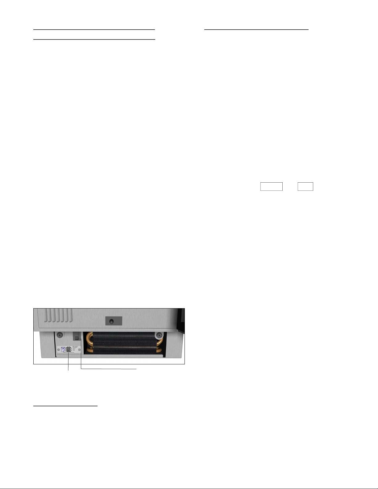
BIN THERMOSTAT / ICE LEVEL
AD JU S TM ENT
The bin thermostat senses when ice has reached
the top of the bin and shuts the machine off.
The thermostat is adjusted at the factory for
room-temperature operation and normally will not
require adjustment.
To check the operation of the bin thermostat, hold
three ice cubes in contact with the thermostat tube
in the bin. The machine should stop making ice
within five minutes. Display will read “FUL”. Then
remove the ice cubes. The machine should then
restart within five minutes.
If necessary, the level of ice in the bin can be
adjusted by turning the bin thermostat screw. This
screw is located just behind the kickplate on the
left side of the machine. Turn the screw clockwise
to raise the ice level, counter-clockwise to lower the
ice level.
Bin thermostat / Ice level adjustment is located
behind front kickplate. Remove front kickplate.
Use a standard screwdriver:
WATER QUALITY SETTING
Your True Ice™ machine may operate differently
depending on the water quality setting of the
machine. To determine your water quality, it is
recommend to purchase a water quality test kit from
a local source.
LOW SCALE (“LSC” ON THE DISPLAY):
When set to LSC, the machine will make ice more
quickly, harvest more quickly and will require a filter
change every 12 months.
HIGH SCALE (“HSC” ON THE DISPLAY):
When set to HSC, the machine will allow more time
for freezing and harvesting ice to compensate for
the presence of scale. The water filter should be
replaced more frequently.
Press and hold the
CLEAN
simultaneously for three seconds to toggle between
the LOW SCALE (“LSC”) and HIGH SCALE (“HSC”)
water quality settings on the machine. Set unit
to LSC when the total dissolved solids (TDS) are
below 300 mg/L. Set unit to “HSC” when the total
dissolved solids (TDS) are above 300 mg/L.
and
SIZE
buttons
RAISE ICE LEVEL - Turn adjustment clockwise to
raise ice level.
LOWER ICE LEVEL - Turn adjustment counterclockwise to lower ice level.
ICE LEVEL ADJUSTMENT
BREAKER SWITCH
BREAKER RESET
The breaker switch is located behind the kickplate.
If the unit trips, flip the switch down. To reset, flip
the switch up.
15 INCH TRUE ICETM MACHINE INSTALL GUIDE
31
Page 37

32
TRUE RESIDENTIAL
®
Page 38

33 - 43
GENERAL MAINTENANCE
WATER SHUTTERS, ICE CHUTE, AND PUMP CLEAN-OUT CAP SPRAY
BAR DISASSEMBLY
WATER FILTER REPLACEMENT AND REPLACEMENT PARTS
CONDENSER CLEANING
STAINLESS STEEL CLEANING INSTRUCTIONS
DESCALING AND SANITIZING
WINTERIZING INSTRUCTIONS AND RESTART
FREQUENTLY ASKED QUESTIONS
WARRANTY
15 INCH TRUE ICETM MACHINE INSTALL GUIDE
33
Page 39

GENERAL MAINTENANCE
You are responsible for maintaining the ice machine
in accordance with the instructions in this manual.
Maintenance procedures are not covered by the
warranty.
WARNING: IF YOU DO NOT UNDERSTAND THE
PROCEDURES OR SAFETY PRECAUTIONS THAT
MUST BE FOLLOWED, CALL YOUR LOCAL TRUE
SERVICE REPRESENTATIVE TO PERFORM THE
MAINTENANCE PROCEDURES FOR YOU.
True recommends that you perform the following
maintenance procedures a minimum of once every
six months to ensure reliable, trouble-free operation.
1. EXTERIOR CLEANING:
Perform as needed. Follow the stainless steel
cleaning instructions listed on page 38 to insure
your machine always looks like new.
2. DESCALING AND SANITIZING:
Perform every six months. Follow the
instructions on pages 38-39 or the instructions
on the inside of the ice machine door.
3. WATER FILTER REPLACEMENT:
Replace the water filter a minimum of every
twelve months. More frequent replacement
may be required if you have poor water quality.
Follow the instructions on page 37.
4. CONDENSER CLEANING:
For optimum operation, clean your condenser
every six months using the instructions on
p a ge 37.
Maintenance Weekly Semi-Annual Annual
Clean Cabinet Exterior
Sanitize Ice Machine
Descale Ice Machine
Clean Condenser Coil
Change the
Water Filter
Check Ice Quality
x x x
x x x x
x x x x
x x x
x x x
x x x x x
After Prolonged
Shutdown
At Start-Up
34
TRUE RESIDENTIAL
®
Page 40
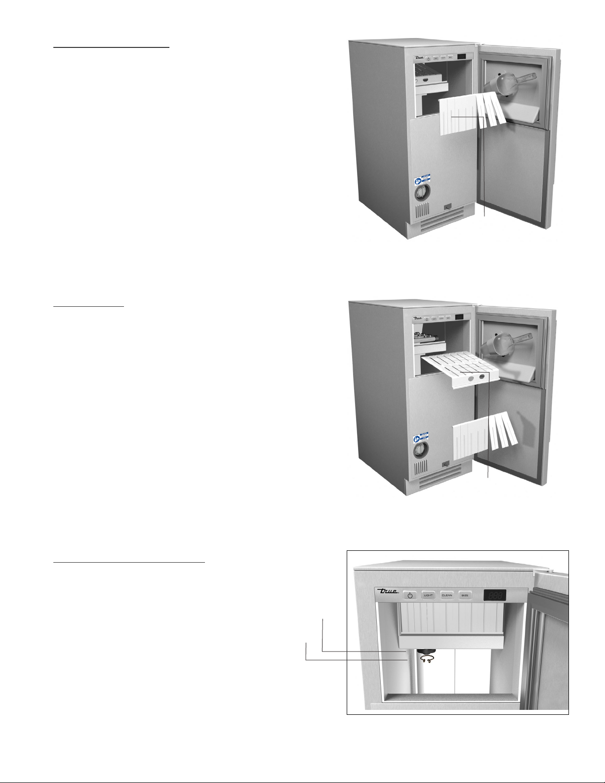
WATER SHUTTERS
Water shutters prevent spraying water from
escaping the evaporator compartment.
Removing water shutters for cleaning:
1. Lift shutter shaft out of recesses on either
end of shaft.
2. To reinstall, insert ends of shaft into
recesses above either side of evaporator
compartment opening.
ICE CHUTE
The ice chute is seated over the spray nozzles
and allows ice to fall into the bin. It must be
firmly positioned over the spray bar, with the front
edge inside the water trough. Spray nozzles must
align with the slots in the ice chute or spray water
will fall into the bin.
WATER SHUTTERS
1. Grab chute and lift up to remove.
2. To reinstall ice chute, grab chute and position
over water spray nozzles. Make sure front
edge is inside of water trough.
PUMP CLEAN-OUT CAP
1. Remove clamp.
2. Pull down clean-out cap.
3. To reinstall, slide cap over hole
underneath pump. Replace clamp.
ICE CHUTE
CAP
CLAMP
15 INCH TRUE ICETM MACHINE INSTALL GUIDE
35
Page 41
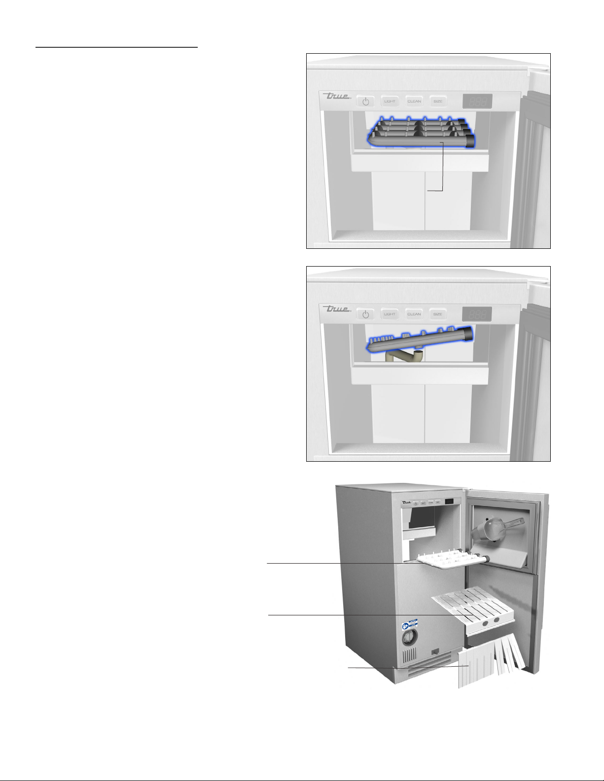
SPRAY BAR DISASSEMBLY
The spray bar is located in the water trough and
supplies water to the individual ice making cups.
Water from the pump sprays through the nozzles,
located on the upper portion of the tubes.
Removing spray bar for cleaning:
1. Grab spray bar with one hand and the water
supply hose (located below spray bar) with the
other hand.
2. Carefully pull the two apart.
3. To reinstall spray bar attach the water supply
hose to the bottom of the spraybar assembly.
Re-seat the spray bar in the evaporator
compartment.
SPRAY BA R
36
TRUE RESIDENTIAL
SPRAY BA R
ICE CHUTE
WATER SHUTTERS
®
Page 42
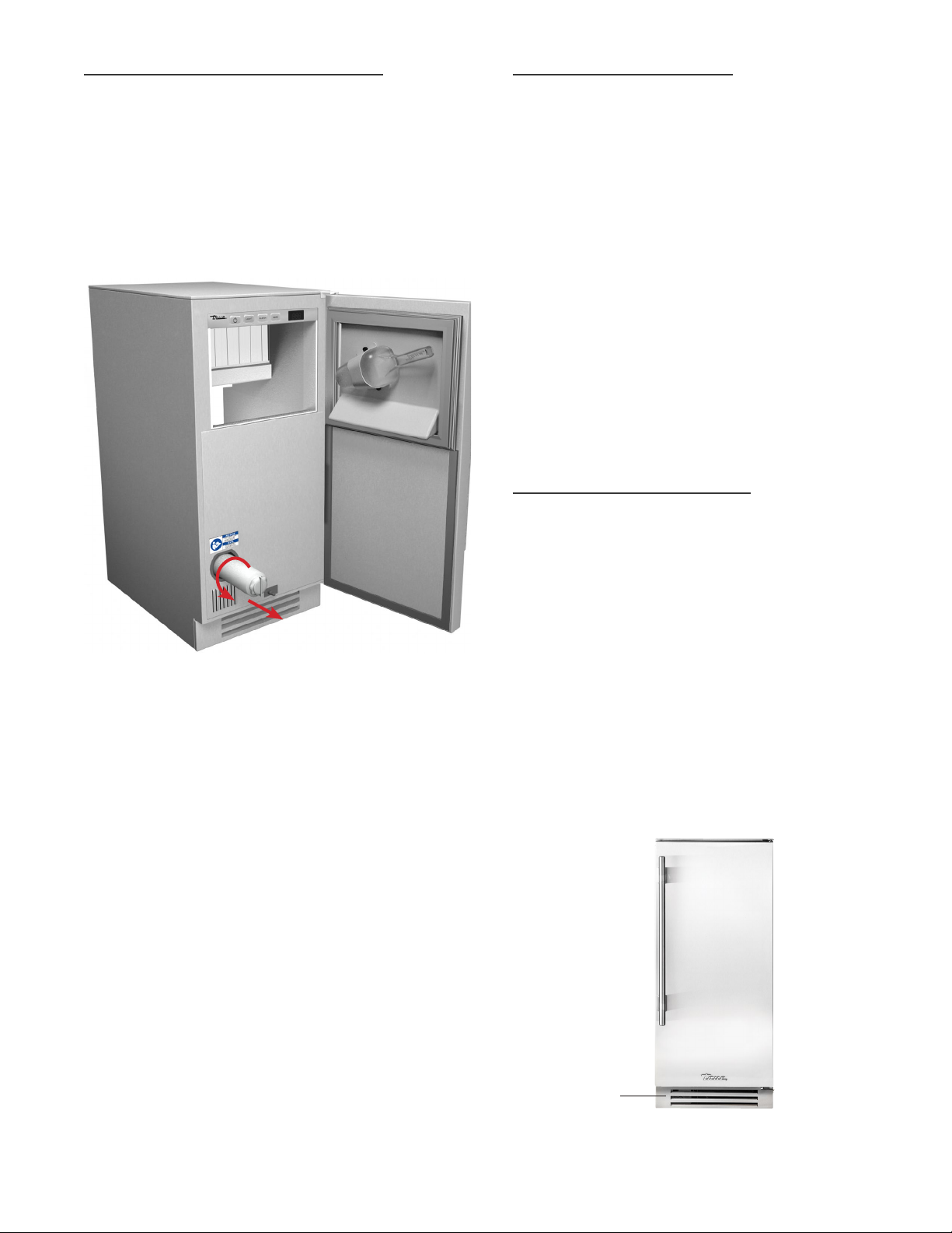
WATER FILTER REPLACEMENT
REPLACEMENT PARTS
The built-in water filter is designed to filter
sediment, remove unpleasant taste and odor and
inhibit scale. The filter is shipped inside the ice
machine and must be installed prior to running the
ice machine. Install the filter by inserting it into the
opening on the front of the machine and twisting it
clockwise to lock it in place.
True maintains a record of the serial number
for your unit. If at any time during the life of
your unit, a part is needed, you may obtain
that part by furnishing the model number and
serial number to the company from whom you
purchased your machine.
For replacement parts contact your True dealer
or call True parts department at 1-800-424-TRUE.
Inquires can be sent to:
(636)240-2400 • toll free (888)616-8783
CONDENSER CLEANING
INSTRUCTIONS
• Keeping the condenser coil clean will minimize
required service and lower electrical cost.
THE ICE MACHINE WILL NOT MAKE ICE IF THE
WATER FILTER IS NOT INSTALLED.
The life expectancy of the filter is twelve months for
low-scale water and six months if the water has a
high level of scale. The ice machine monitors how
long the filter has been in operation and will display
“FLT” when the filter needs to be replaced.
Replacement water filters are available through your
True dealer.
CAUTION: DO NOT ALLOW THE ICE MACHINE TO
BE EXPOSED TO TEMPERATURES BELOW 32˚F
(0˚C) AS THIS WILL CAUSE ANY WATER IN THE
MACHINE OR IN THE WATER FILTER TO FREEZE.
FAILURES CAUSED BY EXPOSURE TO FREEZING
TEMPERATURES ARE NOT COVERED BY THE
WA R RAN T Y.
• The condenser coil should be cleaned by
removing dust and other build-up from the
tube assembly with vacuum or a clean rag.
1. Remove kickplate.
2. Vacuum or use clean rag to remove dust
build-up from coil.
3. Re-install kickplate.
KI CKP L ATE
15 INCH TRUE ICETM MACHINE INSTALL GUIDE
37
Page 43

STAINLESS STEEL EQUIPMENT CARE AND CLEANING
CAUTION: DO NOT USE ANY STEEL WOOL,
ABRASIVE OR CHLORINE BASED PRODUCTS TO
CLEAN STAINLESS STEEL SURFACES.
STAINLESS STEEL OPPONENTS
There are three basic things which can break down
your stainless steel’s passivity layer and allow
corrosion to rear its ugly head.
1. Scratches from wire brushes, scrapers, and steel
pads are just a few examples of items that can be
abrasive to stainless steel’s surface.
2. Deposits left on your stainless steel can leave
spots. You may have hard or soft water depending
on what part of the country you live in. Hard water
can leave spots. Hard water that is heated can
leave deposits if left to sit too long. These deposits
can cause the passive layer to break down and
rust your stainless steel.
All deposits left from food prep or service should
be removed as soon as possible.
3. Chlorides are present in table salt, food, and
water. Household and industrial cleaners are the
worst type of chlorides
to use.
NOTE: THE USE OF STAINLESS STEEL
CLEANERS OR OTHER SUCH SOLVENTS IS NOT
RECOMMENDED ON PLASTIC PARTS. WARM
SOAP AND WATER WILL SUFFICE.
8 STEPS THAT CAN HELP PREVENT RUST ON STAINLESS
STEEL:
1. USING THE CORRECT CLEANING TOOLS
Use non-abrasive tools when cleaning your stainless steel
products. The stainless steel’s passive layer will not be
harmed by soft cloths and plastic scouring pads. Step 2
tells you how to find the polishing marks.
2. CLEANING ALONG THE POLISH LINES
Polishing lines or “grain” are visible on some stainless
steels. Always scrub parallel to visible lines on some
stainless steels. Use a plastic scouring pad or soft cloth
when you cannot see the grain.
3. USE ALKALINE, ALKALINE CHLORINATED OR NON-
CHLORIDE CONTAINING CLEANERS
While many traditional cleaners are loaded with chlorides,
the industry is providing an ever increasing choice of nonchloride cleaners. If you are not sure of your cleaner’s
chloride content contact your cleaner supplier. If they
tell you that your present cleaner contains chlorides,
ask if they have an alternative. Avoid cleaners containing
quaternary salts as they can attack stainless steel, causing
pitting and rusting.
RECOMMENDED CLEANERS FOR CERTAIN SITUATIONS /
ENVIRONMENTS OF STAINLESS STEEL
A. Soap, ammonia and detergent medallion applied
with a cloth or sponge can be used for routine
cleaning.
B. Arcal 20, Lac-O-Nu Ecoshine applied provides
barrier film for fingerprints and smears.
C. Cameo, Talc, Zud First Impression is applied by
rubbing in the direction of the polished lines for
stubborn stains and discoloring.
D. Easy-off and De-Grease It oven aid are excellent
for removals on all finishes for grease-fatty acids,
blood and burnt-on foods.
E. Any good commercial detergent can be applied
with a sponge or cloth to remove grease and oil.
F. Benefit, Super Sheen, Sheila Shine are good for
restoration / passivation.
4. WATER TREATMENT
To reduce deposits, soften the hard water when possible.
Installation of cer tain filters can remove corrosive and
distasteful elements. Salts in a properly maintained water
softener can be to your advantage. Contact a treatment
specialist if you are not sure of the proper water
treatment.
5. MAINTAINING THE CLEANLINESS OF YOUR F OOD
EQUIPMENT
Use cleaners at the recommended strength (alkaline
chlorinated or non-chloride). Avoid build-up of hard
stains by cleaning frequently. When boiling water with
your stainless steel equipment, the single most likely cause
of damage is chlorides in the water. Heating any cleaners
containing chlorides will have the same damaging effects.
6. RINSE
When using chlorinated cleaners you must rinse and wipe
dry immediately. It is better to wipe standing cleaning
agents and water as soon as possible. Allow the stainless
steel equipment to air dry. Oxygen helps maintain the
passivity f ilm on stainless steel.
7. HYDROCHLORIC ACID (MURIATIC ACID) SHOULD NEVER
BE USED ON STAINLESS STEEL
38
TRUE RESIDENTIAL
®
8. REGULARLY RESTORE/PASSIVATE STAINLESS STEEL
Page 44
DESCALING AND SANITIZING
Please follow the instructions below when descaling
and sanitizing your machine.
Hold the
CLEAN
button for three seconds to initiate
the automatic descaling sequence. The descaling
sequence begins by harvesting all the ice from
the evaporator. Once the harvest is complete, the
machine will beep and display “Add” indicating it is
time to add cleaning chemicals to the unit.
After the chemicals have been added, the machine
will go through a sequence of rinse and drain cycles
to descale the machine and drain all the descaling
chemicals from the unit. Once complete, the
machine will resume whatever it was doing to prior
to descaling. If the machine was making ice prior
to pressing the
making. If the machine was off before
CLEAN
button, it will resume ice
CLEAN
was
pressed, it will turn off when descaling is complete.
NOTE: THE DESCALING SEQUENCE CAN BE
CANCELED BY HOLDING THE
CLEAN
BU T T ON
FOR THREE SECONDS.
A full descaling should be performed every six
months. Descaling also involves removing key ice
machine parts and rinsing them and the inside of
the machine with ice machine descaler.
Sanitizing the ice machine is done to remove any
biological contamination that may have occurred.
That process is identical to the descaling process
above except that a sanitizing agent is used in place
of the descaling chemicals.
WARNING: WEAR RUBBER GLOVES AND EYE
PROTECTION WHEN HANDLING ICE MACHINE
DESCALER OR SANITIZER.
PERFORM THE FOLLOWING STEPS EVERY SIX
MONTHS TO FULLY DESCALE OR SANITIZE
YOUR MACHINE.
PERFORM THE HIGHLIGHTED STEPS WHEN ONLY
A LIGHT DESCALING OR SANITIZING IS NEEDED.
DESCALING
1. Remove the ice from bin.
2. Press and hold the
three seconds.
3. When machine says “Add”, pour 6 fl. oz. of
undiluted True Ice™ Machine Descaler into the
spray compartment behind the water shutters.
4. Wait until the rinsing is complete (30 minutes).
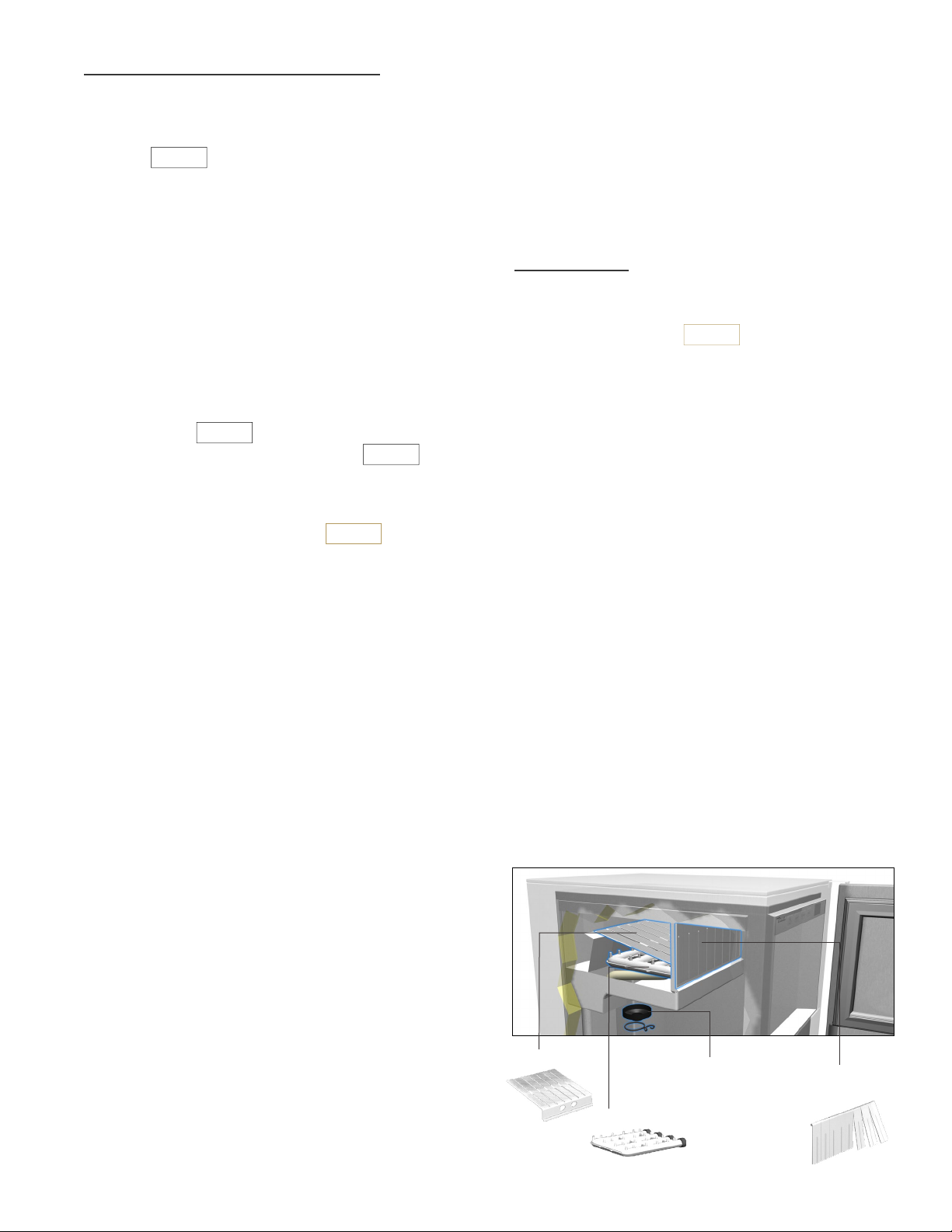
5. Remove the four ice machine parts
illustrated below.
6. Create a descaling solution by mixing 10 fl. oz.
of undiluted True Ice™ Machine Descaler with 1
gallon of water.
7. Using 1/2 of solution, clean removed parts with
a brush then soak them for 20 minutes.
8. Use the remaining solution to descale the ice
bin, the door, the door gasket, the inside of
spray compartment, and the top of evaporator.
9. Rinse all parts with clean water.
CLEAN
button for
CAUTION: DO NOT MIX DESCALER AND
SANITIZER TOGETHER.
ICE CHUTE
PUMP CLEAN-OUT CAP
SPRAY BA R
15 INCH TRUE ICETM MACHINE INSTALL GUIDE
WATER
SHUTTERS
39
Page 45

SANITIZING
WINTERIZING INSTRUCTIONS
1. Mix 1.5 fluid ounces (3 tablespoons) of 5.25%
hypochlorite solution (chlorine bleach) with 3
gallons of warm water.
2. Use 1/2 of the solution to sanitize the removed
parts. Soak the parts in the solution. Do not
rinse the parts after sanitizing.
3. Use the remaining solution to sanitize the
interior surfaces of the machine and the bin.
Do not rinse the sanitized areas.
4. Replace all components.
5. Press and hold the
three seconds.
6. When the machine says “Add”, pour 2 teaspoons
of 5.25% hypochlorite solution (chlorine bleach)
into the spray compartment.
7. When the cleaning cycle is complete, the
machine will resume its previous mode
(either OFF or ICE).
CLEAN
button for
Use the following instructions to prepare your ice
machine for storage or winterization:
1. Descale and sanitize the ice making system per
the instructions on page 39-40.
2. Turn off the water supply.
3. Disconnect the incoming water line from
the back of the unit.
4. Remove the water filter by twisting it counter
clockwise and pulling it out of the unit.
5. Drain the evaporator compartment by removing
the pump clean-out cap per the instructions on
page 35.
6. Switch off and unplug the ice machine.
7. Pour 1 gallon of propylene glycol
(RV antifreeze) into the bin drain to
fill the drain pump.
8. Immediately rinse off and dry any exterior areas
where sanitizing solution may have spilled.
EXTERIOR CLEAN
Wipe with a damp cloth to remove dust and dirt. Use
a solution of mild dish soap and water if a greasy
residue persists. Wipe dry with a clean,
soft cloth. Never use abrasives, chlorinated or
citrus-based cleaners on exterior panels.
RESTART INSTRUCTIONS
Use the following instructions to restart your ice
machine after winterization:
1. Install a new water filter in the unit.
2. Reconnect the incoming water line
and turn on the water supply.
3. Plug in the unit.
4. Descale the ice machine per the instructions on
page 39.
5. Press the power button to start ice making.
NOTE: THE FRESH WATER THAT IS INTRODUCED
DURING DESCALING AND START-UP WILL FLUSH
THE PROPYLENE GLYCOL DOWN THE DRAIN.
40
TRUE RESIDENTIAL
®
Page 46

FREQUENTLY ASKED QUESTIONS
CLEAN
Q. WHY IS THE MACHINE RUNNING BUT NOT MAKING ANY ICE?
A. The machine will run but not make ice if there is no
water supplied to the machine. Check to make sure the
water is turned on and that the water filter is installed
properly.
Q. WHY DOES THE MACHINE SAY “FUL” BUT THE ICE BIN ISN’T
FULL?
A. This is caused by an improperly adjusted thermostat.
Adjust the thermostat as needed using the instructions
on page 31.
Q. WHY IS THERE WARM AIR COMING FROM THE BOTTOM/FRONT
OF THE ICE MACHINE (KICKPLATE AREA)?
A. This is normal as heat dissipation is part of the ice
making process for this machine.
Q. WHY IS THE ICE MACHINE MAKING LESS ICE THAN BEFORE?
A. If the ambient temperature or the water temperature
goes up significantly, the amount of ice the machine
can make will go down. Likewise if the condenser coil
becomes obstructed or dirty, ice production will drop.
For optimal ice production, make sure the front of the
condenser coil, located behind the kickplate, is clean.
Q. WHY DOESN’T THE MACHINE MAKE ICE AFTER I PUT IT
THROUGH A CLEAN CYCLE?
A. After cleaning, the machine will resume doing whatever
it was doing before cleaning. If you want it to make ice
after a clean, make sure it is in the ICE mode when you
press the
button to start cleaning.
Q. WHY IS MY ICE MACHINE NOT MAKING FULL CUBES?
A. Your unit may need to be descaled and/or water filter
may need to be changed.
15 INCH TRUE ICETM MACHINE INSTALL GUIDE
41
Page 47

TRUE ICETM MACHINE WARRANTY
LIMITED 30-DAY COSMETIC WARRANTY
Stainless steel doors and handles are warranted to
be free from defective materials and workmanship
for a period of thirty (30) days from the date of
original retail purchase. Any defects must be
reported to the selling dealer within thirty (30) days
from the date of original retail purchase. This limited
warranty excludes any type of freight / concealed
damage.
THREE-YEAR PARTS & LABOR WARRANTY
TRUE warrants to the original purchaser of every
new True Ice™ machine, the cabinet and all parts
thereof, to be free from defects in material and
workmanship under normal and proper use and
maintenance as specified by TRUE and upon proper
installation and start-up in accordance with the
instruction packet supplied with each TRUE unit.
TRUE’s obligation under this warranty is limited to
a period of three (3) years from the date of original
installation or thirty-nine (39) months after shipment
date from TRUE, whichever occurs first.
SIX-YEAR SEALED SYSTEM WARRANTY - PARTS & LABOR
TRUE warrants its hermetically sealed system:
compressor, evaporator coil, condenser coil, drier,
metering device and connecting tubing to be free
from defects in both material and workmanship
under normal and proper use and maintenance
service for a period of six (6) years from the date
of original installation but not to exceed six (6)
years and three (3) months after shipment from the
manufacturer, whichever occurs first.
WARRANTY CLAIMS
All claims for labor or parts must be made directly
through TRUE. All claims should include: model
number and serial number of ice machine, proof
of purchase, and date of installation. In case of
warranted compressor, the compressor model tag,
or picture of tag must be returned to TRUE along
with the above listed information. Warranty labor
claim is subject to denial if failed part is requested
for return and it is not returned.
WHAT IS NOT COVERED BY THIS WARRANTY
TRUE’s sole obligation under this warranty is limited
to either repair or replacement of parts, subject to
the additional limitations below.
This warranty neither assumes nor authorizes any
person to assume obligations other than those
expressly covered by this warranty. This warranty
does not cover failures related to the water supply,
problems in the plumbing going to the unit, or
external drain line malfunctions. Also not covered
are failures resulting from ambient conditions
that are outside the limits specified in the owners
manual.
NO CONSEQUENTIAL DAMAGES
TRUE is not responsible for economic loss, profit
loss or special, indirect or consequential damages,
including without limitation, losses or damages
arising from ice loss or ice replacement costs,
normal maintenance,
after-install adjustments or cleaning or water
damage claims whether or not on account of
refrigeration failure.
TERMS APPLICABLE TO EACH WARRANTY
Any part covered under the above warranties that
is determined by TRUE to have been defective
within the time frame is limited to the repair or
replacement, including labor charges, of defective
parts or assemblies. The labor warranty shall
include standard straight time labor charges only
and reasonable travel time, as determined by TRUE.
42
TRUE RESIDENTIAL
®
Page 48

WARRANTY IS NOT TRANSFERABLE
This warranty is not assignable and applies only
in favor of the original purchaser / user to whom
delivered. Any such assignment or transfer shall
void the warranties herein made and shall void
all warranties, express or implied, including
any warranty or merchantability or fitness for a
particular purpose.
IMPROPER USAGE
TRUE assumes no liability for parts or labor
coverage for component failure or other damages
resulting from improper usage or installation or
failure to clean and / or maintain product as set
forth in the users manual provided with the unit.
IMPROPER ELECTRICAL CONNECTIONS
TRUE is not responsible for the repair or
replacement of failed or damaged components
resulting from electrical power failure, high or
low voltage, use of extension cords, or improper
grounding of the unit.
NO IMPLIED WARRANTY
There are no other warranties, expressed, implied
or statutory except the 30-day cosmetic, three-year
parts and labor and six-year sealed system warranty
as described above. These warranties are exclusive
and in lieu of all other warranties, including implied
warranty and merchantability or fitness for a
particular purpose. There are no warranties that
extend beyond the description on the face hereof.
ALTERATION OR NEGLECT
TRUE is not responsible for the repair or
replacement of any parts that TRUE determines
have been subjected, after the date of manufacture,
to alteration, neglect, abuse, misuse, accident,
damage during transit or installation, fire, flood, or
act of God.
Some states do not allow the exclusion or limitation
of consequential damages or a limitation on how
long an implied warranty lasts, so the above
exclusion or limitation may not apply to you. This
warranty gives you specific legal rights and you may
have other rights that vary from state to state.
OUTSIDE U.S. / CANADA
This warranty does not apply to, and TRUE is not
responsible for, any warranty claims made on
products sold or used outside the United States or
Canada.
15 INCH TRUE ICETM MACHINE INSTALL GUIDE
43
Page 49

N O T E S
Page 50

CONTACT US
AL
•
9749 89
•
7/15
www.true-residential.com
(636)240-2400 • toll free (888)616-8783
2001 East Terra Lane
O’Fallon, MO 63366
 Loading...