

Page 1
TRUE
food service equipment, inc.
CONGRATULATIONS!
You have just purchased the finest commercial refrigerator
available. You can expect many years of trouble-free operation.
TABLE OF CONTENTS
SAFETY INFORMATION
Safety Precautions 1
Proper Disposal, Connecting Electricity, & Adapter Plugs 2
INSTALLATION
Ownership, Uncrating, & How to Connect to Electricity 3
Wire Gauge Chart 4
Locating and Leveling 5
Installation of Legs or Castors 6
SETUP
Standard Accessories 7
OPERATION
Startup 7
Mechanical Temperature Controls Sequence of Operation 8
Electronic Temperature Controls Sequence of Operation 14
INSTALLATION MANUAL
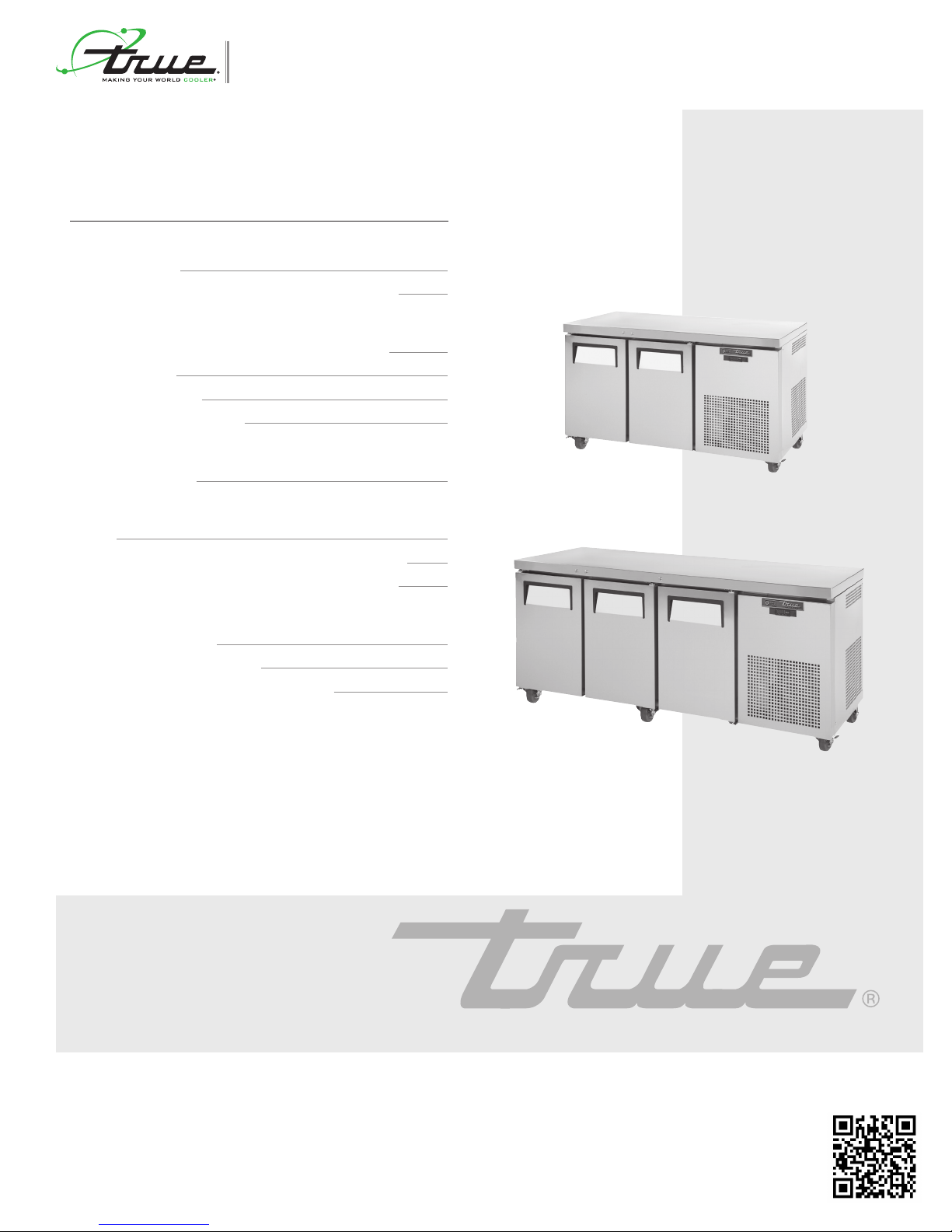
tgu
TGU-2-HC
MAINTENANCE, CARE, CLEANING
Cleaning Condenser Coil 23
Important Warranty Information 24
Stainless Steel Equipment Care and Cleaning 25
TGU-3-HC
INSTALLATION MANUAL
TRUE FOOD SERVICE EQUIPMENT, INC.
2001 East Terra Lane • O’Fallon, Missouri 63366-4434
(636)-240-2400 • FAX (636)-272-2408 • INT'L FAX (636)272-7546 • (800)-325-6152
Parts Department (800)-424-TRUE • Parts Department FAX# (636)-272-9471
Web: www.truemfg.com
gastronorm undercounters
975554
AC · MISC1914 · 05. 04 .20 17 ·975554
Page 2
TRUE
tgu/tgw
www.truemfg.com
NOTICE TO CUSTOMER
Loss or spoilage of products in your refrigerator/
freezer is not covered by warranty. In addition to
following recommended installation procedures
you must run the refrigerator/freezer 24 hours
prior to usage.
SAFETY INFORMATION
How to Maintain Your True Refrigerator to Receive the Most Efficient and Successful Operation.
You have selected one of the finest commercial refrigeration units made. It is manufactured under strict quality controls with only the best
quality materials available. Your TRUE cooler when properly maintained will give you many years of trouble-free service.
WARNING: Use this appliance for its intended purpose as described in this Owner Manual.
TO LOCATE REFRIGERANT TYPE, SEE SERIAL LABEL INSIDE CABINET. This cabinet may contain fluorinated greenhouse
gas covered by the Kyoto Protocol (please refer to cabinet’s inner label for type and volume, GWP of 134a= 1,300. R404a= 3,800).
FOR HYDROCARBON REFRIGERATION ONLY (R-290) SEE BELOW:
• DANGER - Risk of fire or explosion. Flammable refrigerant used. Do not use mechanical devices to defrost refrigerator. Do not
puncture refrigerant tubing.
• DANGER - Risk of fire or explosion. Flammable refrigerant used. To be repaired only by trained service personnel. Do not puncture
refrigerant tubing.
• CAUTION - Risk of fire or explosion. Flammable refrigerant used. Consult repair manual/owner’s guide before attempting to service
this product. All safety precautions must be followed.
• CAUTION - Risk of fire or explosion. Dispose of properly in accordance with federal or local regulations. Flammable refrigerant used.
• CAUTION - Risk of fire or explosion due to puncture of refrigerant tubing; follow handling instructions carefully. Flammable refrigerant
used.
• CAUTION - Keep clear of obstruction all ventilation openings in the appliance enclosure or in the structure for building-in.
SAFETY PRECAUTIONS
When using electrical appliances, basic safety precautions should be
followed, including the following:
• This refrigerator must be properly installed and located in
accordance with the Installation Instructions before it is used.
• Do not allow children to climb, stand or hang on the shelves
in the refrigerator. They could damage the refrigerator and
seriously injure themselves.
• Do not touch the cold surfaces in the freezer compartment
when hands are damp or wet. Skin may stick to these
extremely cold surfaces.
• Do not store or use gasoline or other flammable vapors and
liquids in the vicinity of this or any other appliance. Do not store
explosive substances such as aerosol cans with a flammable
propellant in this appliance.
• Keep f ingers out of the “pinch point” areas; clearances between
the doors and between the doors and cabinet are necessarily
small; be careful closing doors when children are in the area.
• Unplug the refrigerator before cleaning and making repairs.
• Setting temperature controls to the 0 position does not
remove power to the light circuit, perimeter heaters, or
evaporator fans.
NOTE: We strongly recommend that any servicing be preformed
by a qualified technician.
1
Page 3

TRUE
208-230/60/1
tgu/tgw
www.truemfg.com
WARNING!DANGER
RISK OF CHILD
ENTRAPMENT
PROPER DISPOSAL OF THE REFRIGERATOR
Child entrapment and suffocation are not problems of the past.
Junked or abandoned refrigerators are still dangerous… even if they
will sit for “just a few days.” If you are getting rid of your old refrigerator, please follow the instructions below to help prevent accidents.
BEFORE YOU THROW AWAY YOUR OLD
REFRIGERATOR OR FREEZER:
• Take off the doors.
• Leave the shelves in place so that children may not easily climb
inside.
APPLIANCE DISPOSAL
When recycling appliance please make sure that the refrigerants are
handled according to local and national codes, requirements and
regulations.
REFRIGERANT DISPOSAL
Your old refrigerator may have a cooling system that uses “Ozone
Depleting” chemicals. If you are throwing away your old refrigerator,
make sure the refrigerant is removed for proper disposal by a qualified service technician. If you intentionally release any refrigerants you
can be subject to fines and imprisonment under provisions of the
environmental regulations.
USE OF EXTENSION CORDS
NEVER USE AN EXTENSION CORD! TRUE will not war-
ranty any refrigerator that has been connected to an extension cord.
REPLACEMENT PARTS
• Component parts shall be replaced with like components.
• Servicing shall be done by authorized service personnel, to
minimize the risk of possible ignition due to incorrect parts or
improper service.
• Lamps must be replaced by identical lamps only.
• If the supply cord is damaged, it must be replaced by a special
cord or assembly available from the manufacturer or its service
agent.
HOW TO CONNECT ELECTRICITY
DO NOT, UNDER ANY CIRCUMSTANCES, CUT OR
REMOVE THE GROUND PRONG FROM THE POWER
CORD. FOR PERSONAL SAFETY, THIS APPLIANCE
MUST BE PROPERLY GROUNDED.
The power cord from this appliance is equipped with a grounding
plug which minimizes the possibility of electric shock hazard.
Have the wall outlet and circuit checked by a qualified electrician to
make sure the outlet is properly grounded.
If the outlet is a standard 2-prong outlet, it is your personal responsibility and obligation to have it replaced with the properly grounded
wall outlet.
The refrigerator should always be plugged into it’s own individual
electrical circuit, which has a voltage rating that matches the rating
plate.
This provides the best performance and also prevents overloading
building wiring circuits which could cause a fire hazard from overheated wires.
Never unplug your refrigerator by pulling on the power cord. Always
grip plug firmly and pull straight out from the outlet.
Repair or replace immediately all power cords that have become
frayed or otherwise damaged. Do not use a cord that shows cracks
or abrasion damage along its length or at either end.
When removing the refrigerator away from the wall, be careful not
to roll over or damage the power cord.
If supply power cord is damaged it should be replaced with original
equipment manufacture parts. To avoid hazard this should be done
by a qualified service technician.
USE OF ADAPTER PLUGS
NEVER USE AN ADAPTER PLUG! Because of potential safety
hazards under certain conditions, we strongly recommend against the
use of an adapter plug.
The incoming power source to the cabinet including any adapters
used must have the adequate power available and must be properly
grounded. Only adapters listed with UL should be used.
NORTH AMERICA USE ONLY!
NEMA plugs
TRUE uses these types of plugs. If you do not have the right outlet
have a certified electrician install the correct power source.
NOTE: International plug configurations vary by voltage and country.
115/60/1
NEMA-5-15R
115/208-230/1
NEMA-14-20R
115/60/1
NEMA-5-20R
NEMA-6-15R
2
Page 4
TRUE
tgu/tgw
INSTALLATION
www.truemfg.com
OWNERSHIP
To ensure that your unit works properly from the first day, it must
be installed properly. We highly recommend a trained refrigeration
mechanic and electrician install your TRUE equipment. The cost of a
professional installation is money well spent.
Before you start to install your TRUE unit, carefully inspect it for
freight damage. If damage is discovered, immediately file a claim with
the delivery freight carrier.
TRUE is not responsible for damage incurred during shipment.
TOOLS REQUIRED
• Adjustable Wrench
• Phillips Screwdriver
• Level
UNCRATING
The following procedure is recommended for uncrating the unit:
A. Remove the outer packaging, (cardboard and bubbles or
styrofoam corners and clear plastic). Inspect for concealed
damage. Again, immediately file a claim with the freight carrier
if there is damage.
B. Move your unit as close to the final location as possible before
removing the wooden skid.
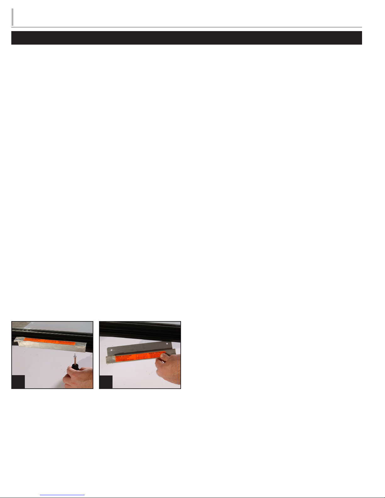
C. Remove door bracket on swinging glass door models (see
image 1-2). Do not throw the bracket or blocks away. For
future cabinet movement the bracket and blocks will need to
be installed so the glass door does not receive any damage.
(See image for bracket and shipping block removal)
ELECTRIC INSTALLATION & SAFETY
INFORMATION
• If the supply cord is damaged, it must be replaced by a special
cord or assembly available from the manufacturer or its service
agent.
• Lamps must be replaced by identical lamps only.
• Appliance tested according to the climate classes 5 and 7
temperature and relative humidity.
ELECTRICAL INSTRUCTIONS
A. Before your new unit is connected to a power supply, check the
incoming voltage with a voltmeter. If anything less than 100% of
the rated voltage for operation is noted, correct immediately.
B. All units are equipped with a service cord, and must be
powered at proper operating voltage at all times. Refer to
cabinet data plate for this voltage.
TRUE RECOMMENDS THAT A SOLE USE CIRCUIT BE
DEDICATED FOR THE UNIT.
WARNING: Compressor warranties are void if compressor burns
out due to low voltage.
WARNING: Power supply cord ground should not be removed!
WARNING: Do not use electrical appliances inside the food
storage compartments of the appliances unless they are of the type
recommended by the manufacturer.
NOTE: To reference wiring diagram, remove front louvered grill,
wiring diagram is positioned on the inside cabinet wall.
NOTE: KEYS FOR COOLERS WITH DOOR LOCKS
ARE LOCATED IN WARRANTY PACKETS.
1
2
3
Page 5

TRUE
tgu/tgw
WIRE GAUGE CHART
www.truemfg.com
115 Volt s Distance In Feet To Center of Load
Amps 20 30 40 50 60 70 80 90 100 120 140 160
2 14 14 14 14 14 14 14 14 14 14 14 14
3 14 14 14 14 14 14 14 14 14 14 14 12
4 14 14 14 14 14 14 14 14 14 12 12 12
5 14 14 14 14 14 14 14 12 12 12 10 10
6 14 14 14 14 14 14 12 12 12 10 10 10
7 14 14 14 14 14 12 12 12 10 10 10 8
8 14 14 14 14 12 12 12 10 10 10 8 8
9 14 14 14 12 12 12 10 10 10 8 8 8
10 14 14 14 12 12 10 10 10 10 8 8 8
12 14 14 12 12 10 10 10 8 8 8 8 6
14 14 14 12 10 10 10 8 8 8 6 6 6
16 14 12 12 10 10 8 8 8 8 6 6 6
18 14 12 10 10 8 8 8 8 8 8 8 5
20 14 12 10 10 8 8 8 6 6 6 5 5
25 12 10 10 8 8 6 6 6 6 5 4 4
30 12 10 8 8 6 6 6 6 5 4 4 3
35 10 10 8 6 6 6 5 5 4 4 3 2
40 10 8 8 6 6 5 5 4 4 3 2 2
45 10 8 6 6 6 5 4 4 3 3 2 1
50 10 8 6 6 5 4 4 3 3 2 1 1
230 Volts Distance In Feet To Center of Load
Amps 20 30 40 50 60 70 80 90 100 120 140 160
5 14 14 14 14 14 14 14 14 14 14 14 14
6 14 14 14 14 14 14 14 14 14 14 14 12
7 14 14 14 14 14 14 14 14 14 14 12 12
8 14 14 14 14 14 14 14 14 14 12 12 12
9 14 14 14 14 14 14 14 14 12 12 12 10
10 14 14 14 14 14 14 14 12 12 12 10 10
12 14 14 14 14 14 14 12 12 12 10 10 10
14 14 14 14 14 14 12 12 12 10 10 10 8
16 14 14 14 14 12 12 12 10 10 10 8 8
18 14 14 14 12 12 12 10 10 10 8 8 8
20 14 14 14 12 10 10 10 10 10 8 8 8
25 14 14 12 12 10 10 10 10 8 8 6 6
30 14 12 12 10 10 10 8 8 8 6 6 6
35 14 12 10 10 10 8 8 8 8 6 6 5
40 14 12 10 10 8 8 8 6 6 6 5 5
50 12 10 10 8 6 6 6 6 6 5 4 4
60 12 10 8 6 6 6 6 6 5 4 4 3
70 10 10 8 6 6 6 5 5 4 4 2 2
80 10 8 8 6 6 5 5 4 4 3 2 2
90 10 8 6 6 5 5 4 4 3 3 1 1
100 10 8 6 6 5 4 4 3 3 2 1 1
4
Page 6
TRUE
tgu/tgw
www.truemfg.com
LOCATING
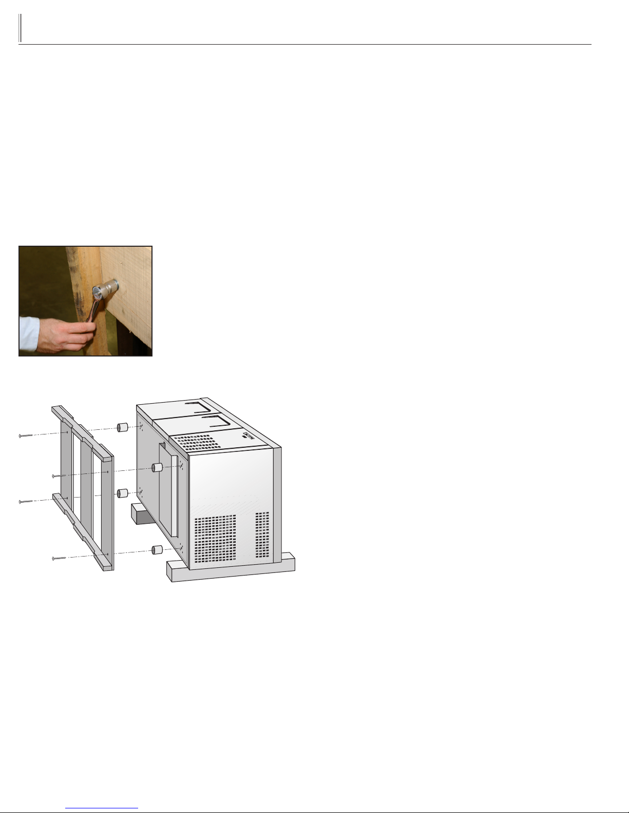
A. Remove packing material behind cabinet as a cushion. Carefully
lay the unit on its back to remove skid.
When lifting unit remember to leave the cabinet upright for 24 hours
before plugging into power source.
B. Remove skid by unscrewing all base rail anchor brackets. Place
skid to the side.
C. Carefully lift cabinet upright.
D. Applicance tested according to the climate classes 5 and 7 for
temperature and relative humidity.
Removing skid from bottom of
cabinet.
LEVELING
A. Set unit in its final location. Be sure there is adequate ventilation
in your room. Under extreme heat conditions, (100°F+,
38°C+), you may want to install an exhaust fan.
WARNING: WARRANTY IS VOID IF VENTILATION IS
INSUFFICIENT.
B. Proper leveling of your TRUE cooler is critical to operating
success (for non-mobile models). Effective condensate removal
and door operation will be effected by leveling.
C. The cooler should be leveled front to back and side to side with
a level.
D. Ensure that the drain hose or hoses are positioned in the pan.
E. Free plug and cord from inside the lower rear of the cooler
(do not plug in).
F. The unit should be placed close enough to the electrical supply
so that ex tension cords are never used.
NOTE: If the cabinet has a center leveling screw, castor, or leg,
make sure it is adjusted properly so it makes full contact with the
floor after the cabinet has been leveled.
WARNING: CABINET WARRANTIES ARE VOID
IF OEM POWER CORD IS TAMPERED WITH. TRUE
WILL NOT WARRANTY ANY UNITS THAT ARE
CONNECTED TO AN EXTENSION CORD.
5
Page 7
TRUE
tgu/tgw
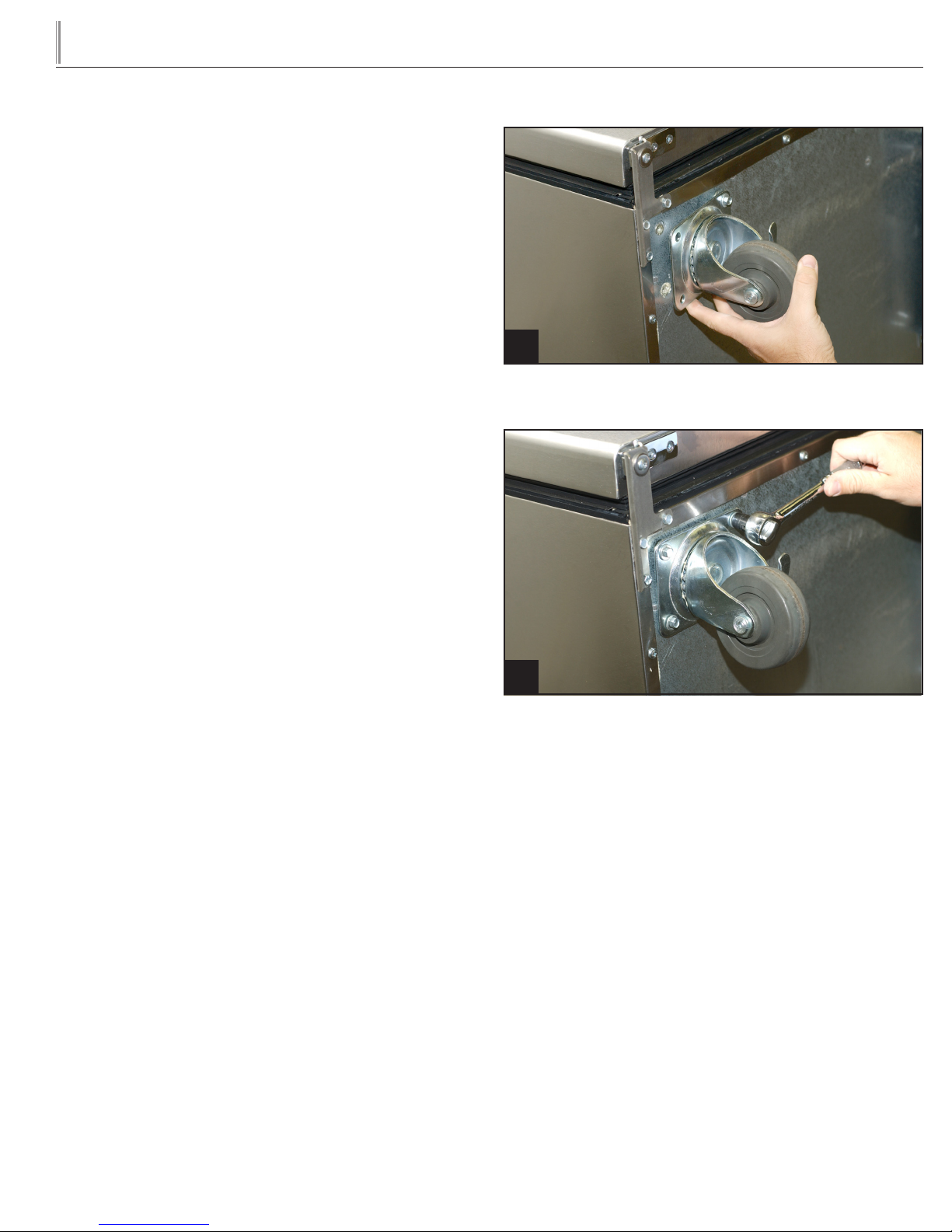
INSTALLATION OF CASTORS OR
OPTIONAL LEGS
SECURING CASTORS
To obtain maximum strength and stability of the unit, it is important
that you make sure each castor is secure. The bearing race on the
castor of the top edge of the leg must make firm contact with the rail.
UNIT LEVELING
Four leveling shims have been provided for leveling castored units
positioned on uneven floors. Shims must be positioned between rail
end and bearing race. TRUE recommends a four shim limit to any
single castor.
A. Turn the bearing race counter-clockwise until the cabinet is
level. Level front to back and side to side. (diagonally)
B. Install the desired number of shims, making sure the slot of the
shim is in contact with the threaded stem of the castor.
C. If more than one shim is used, turn the slot at a 90° angle so
they are not in line.
D. Turn the bearing race clockwise to tighten and secure the
castor by tightening the anchoring bolt with a 3/4 inch openend wrench, socket, or the tool provided.
www.truemfg.com
1
Thread four screws into castor in the underside of cabinet frame rail.
CAUTION
To avoid damage to lower rail assembly, slowly raise unit to upright
position after installing castors.
2
Anchor the four screws rmly to the base of the unit.
6
Page 8
TRUE
tgu/tgw
SETUP
STANDARD ACCESSORIES
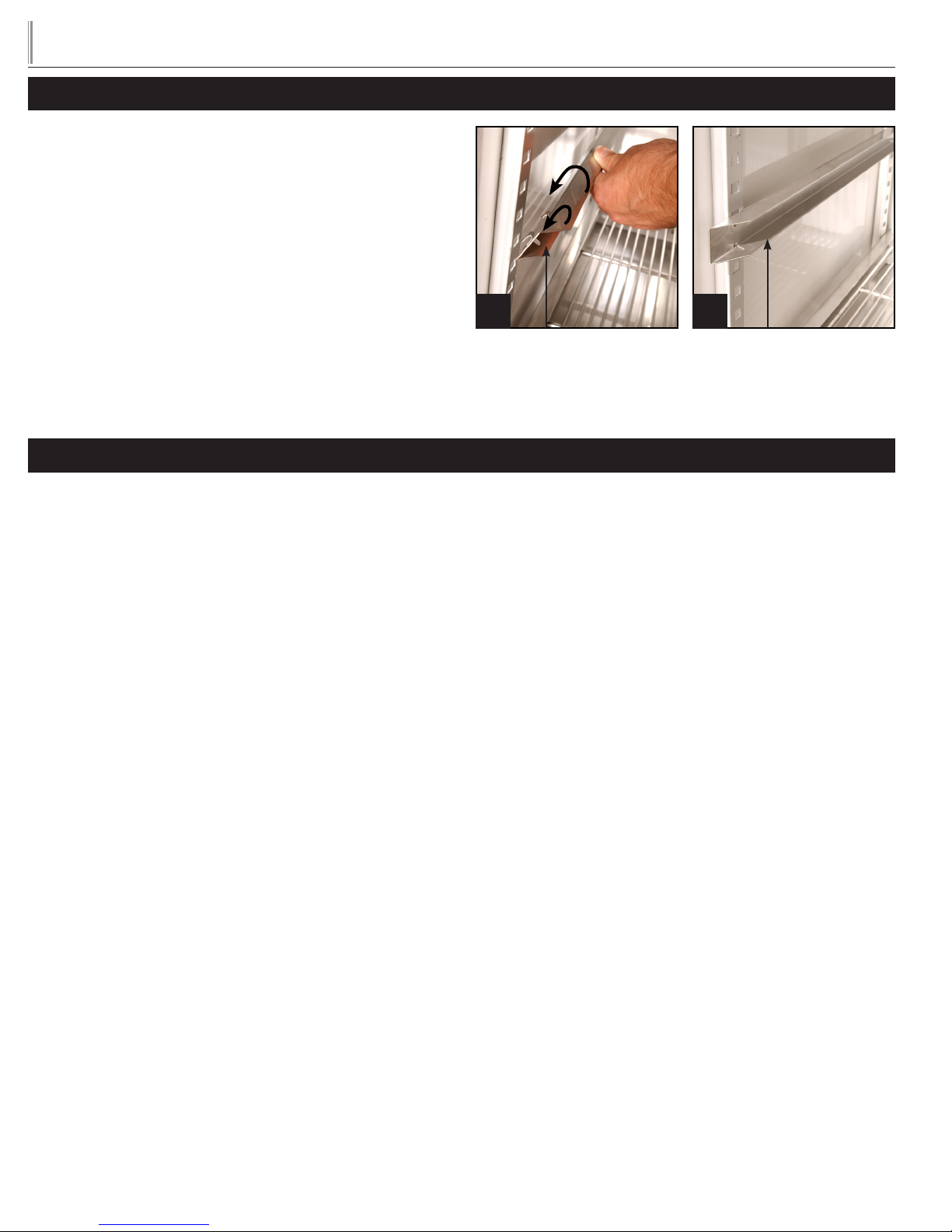
SHELVING INSTALLATION / OPERATION
STEP 1 - Position tray slide to align front to back (level) with rectan-
gular hole of the standard posts. Make sure tabs on the back-side of
the tray slide are facing down. Push in and slide down on both ends
so tabs are in the locked position. (See figure 1).
NOTE: Make sure that pan slide is level front to back within the
refrigerator or freezer.
STEP 2 - Repeat procedure with remaining tray slides.
NOTE: Figure 2 illustrates correct installation of tray slide.
OPERATION
1 2
Tray S lide
www.truemfg.com
Tray S lide
STARTUP
A. The compressor is ready to operate. Plug in the cooler.
B. Temperature controls are factory-set to give refrigerators
an approximate temperature of 35°F (1.7°C) and freezers
an approximate temperature of -10°F (-23.3°C). Allow unit
to function several hours, completely cooling cabinet before
changing the control setting.
Temperature Control Location and Settings.
• Temperature control type will vary upon model and age of
cabinet.
• Mechanical control or electronic control without display:
- Inside cabinet
- Behind cabinet
- Behind front or rear access grill
• Electronic control with display:
- In counter top
- In top louvered panel
- In or behind bottom louvered grill
See website for adjustments, sequence of operation, and more
information.
C. Excessive tampering with the control could lead to service
difficulties. Should it ever become necessar y to replace
temperature control, be sure it is ordered from your TRUE
dealer or recommended service agent.
D. Good air flow in your TRUE unit is critical. Be careful to
load product so that it neither presses against the back wall,
nor comes within four inches of the evaporator housing.
Refrigerated air off the coil must circulate down the back wall.
NOTE: If the unit is disconnected or shut off, wait five minutes
before starting again.
RECOMMENDATION - Before loading product we recommend
you run your TRUE unit empty for two to three days. This allows
you to be sure electrical wiring and installation are correct and no
shipping damage has occurred. Remember, our factory warranty does
not cover product loss!
7
Page 9
TRUE
tgu/tgw
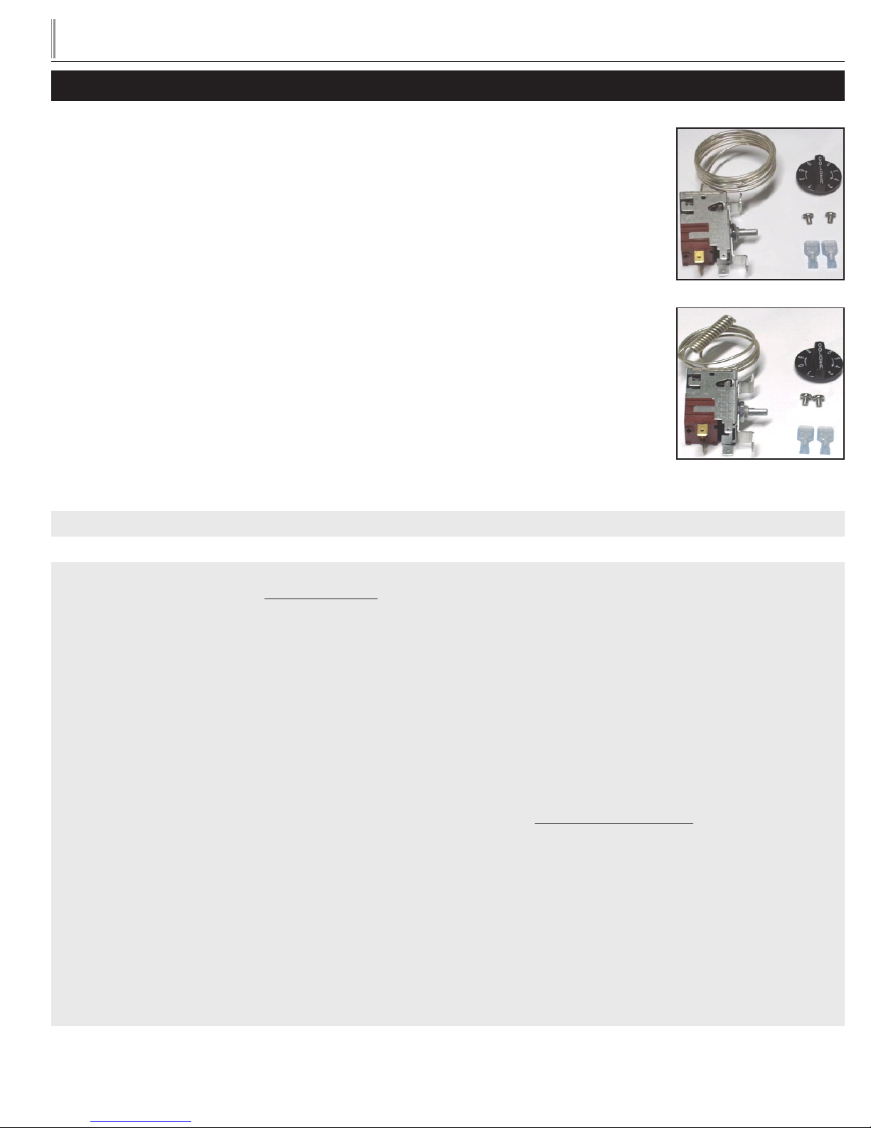
MECHANICAL TEMPERATURE CONTROLS
COIL SENSING
An evaporator coil sensing temperature control ensures that the evaporator coil will remain clear of frost
and ice by not allowing the compressor to restart until the coil temperature is above the freezing temperature. This is considered an off cycle defrost.
AIR SENSING
An air sensing temperature control used in a freezer application will require a defrost cycle with heaters to
ensure that the evaporator coil is kept clear of frost and ice.
www.truemfg.com
MECHANICAL TEMPERATURE CONTROL GENERAL SEQUENCE OF OPERATION
MECHANICAL CONTROL REFRIGERATOR GENERAL SEQUENCE OF OPERATION
1. Cabinet is plugged in.
a. Interior lights will illuminate on Glass Door Models only. If lights do not come on verify the light switch is in the “ON”
position. Solid door cabinets may or may not have lights that may be controlled by the door switch.
2. The compressor and evaporator fans will star t if the temperature control is calling for cooling. (If the compressor does not
start, verify that the temperature control is not in the “OFF” or “0” position.)
3. The temperature control may cycle the compressor and evaporator fan(s) on and off together.
a. The temperature control is sensing the evaporator coil temperature.
b. The temperature control should be set on the #4 or #5.
c. The warmest setting is #1, the coldest is #9, and #0 is the off position.
d. The thermometer is designed to read and display a cabinet temperature not a product temperature.
The thermometer may reflect the refrigeration cycle swings of up and down temperatures.
The most accurate temperature on a cabinet's operation is to verify the product temperature.
4. There is not a defrost timer as the temperature control will initiate the off-cycle defrost during each refrigeration cycle.
a. At this time, the compressor will and the evaporator fan(s) may turn off. Defrost heaters are not installed on refrigerators
and therefore will not be energized.
b. After the evaporator coil temperature has been reached, as determined by the temperature control, the compressor will
restart.
5. There may be a timer located on the condensing unit base. This timer is not used for a defrost event. The timer will change
the rotation of the reversing condenser fan motor.
8
Page 10

TRUE
tgu/tgw
MECHANICAL CONTROL FREEZER GENERAL SEQUENCE OF OPERATION
1. Cabinet is plugged in.
a. Interior lights will illuminate on glass door models only. If lights do not come on, verify the light switch is in
the “ON” position. Solid door cabinets may or may not have lights that may be controlled by the door switch.
2. The compressor only will start if the temperature control is calling for cooling. (If the compressor does not start, verify that
the temperature control is not in the “OFF” or “0” position or the cabinet is not in a defrost event.)
a. The evaporator fan(s) will remain off until a specific temperature of the evaporator coil is reached.
3. The temperature control may cycle the compressor and evaporator fan(s) on and off together.
a. The temperature control is sensing the air temperature.
b. The temperature control should be set on the #4 or #5.
c. The warmest setting is #1, the coldest is #9, and #0 is the off position.
d. The thermometer is designed to read and display a cabinet temperature not a product temperature.
The thermometer may ref lect the refrigeration cycle swings of up and down temperatures.
The most accurate temperature on a cabinet's operation is to verify the product temperature.
www.truemfg.com
4. The defrost timer will initiate defrost during specific times of day.
a. At this time, the compressor and evaporator fan(s) will turn off and the evaporator coil heater and drain tube heater will
be energized. Some cabinets may also change the rotation of the reversing condenser fan motor.
b. After the predetermined evaporator coil temperature has been reached or duration for defrost has expired, the
compressor will restart and the evaporator fan(s) will remain off until a specific temperature of the evaporator coil
is reached.
9
Page 11
TRUE
60
45
15
tgu/tgw
WHEN TO MAKE AN ADJUSTMENT TO A MECHANICAL TEMPERATURE CONTROL
We advise to make a mechanical temperature control adjustment only for a high altitude location.
HOW TO ADJUST A MECHANICAL TEMPERATURE CONTROL
www.truemfg.com
OPERATION INSTRUCTIONS:
REQUIRED TOOLS:
• Jewelers Screw Driver (Small Screw Driver)
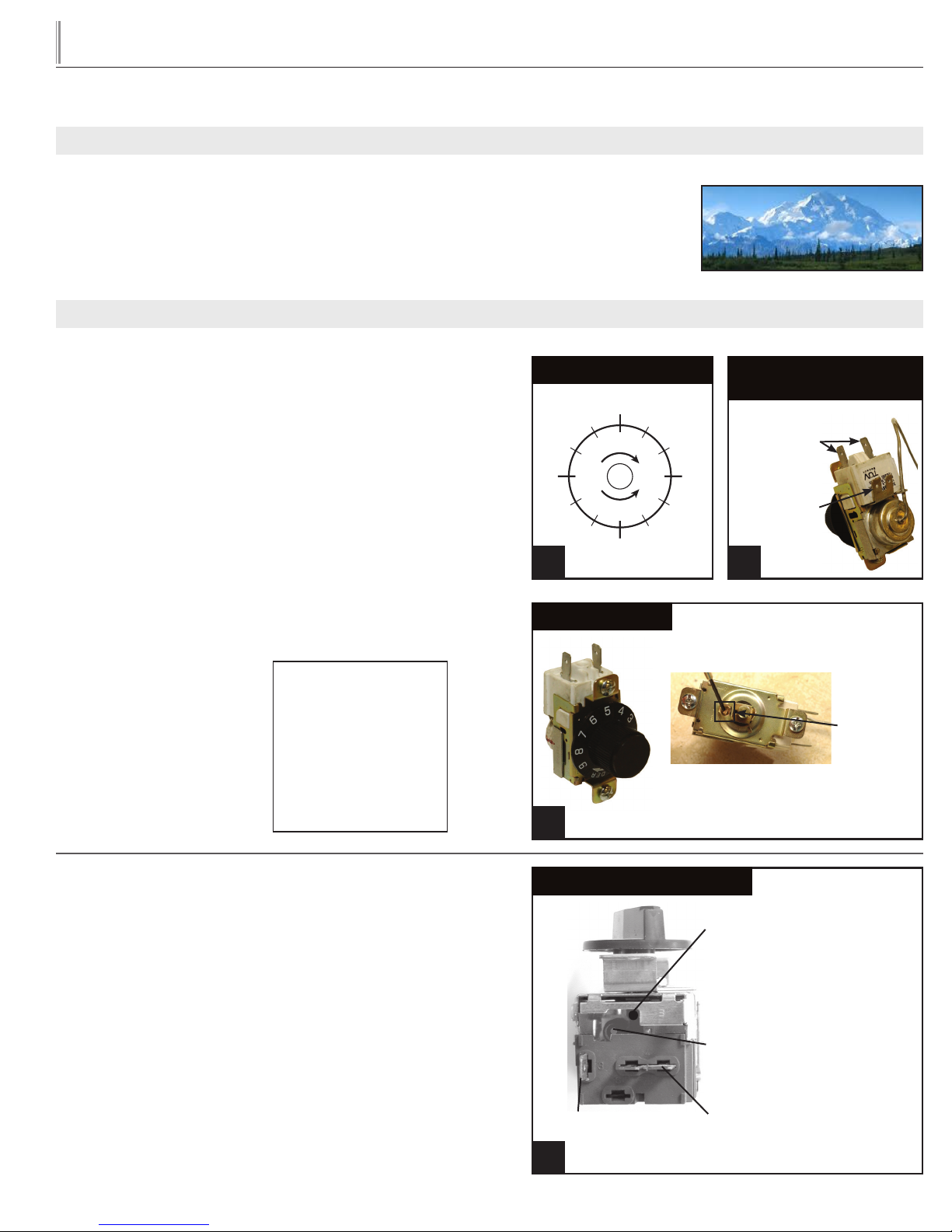
GE CONTROL INSTRUCTIONS:
The scale to the right may be used as a guide for measuring
degrees of rotation required for altitude correction. See Figure 1.
The arrows indicate direction of screw rotation. Turn calibration
screw clockwise to obtain warmer operating temperatures.
NOTE: Each 1/4 turn of the calibration screw is equal to
approximately 2 degrees F. Do not make more than 3/4 turn.
After making adjustment, measure temperature during three
cycles before adjusting again.
NOTE: Only adjust the screw
(small flathead) on the face of
the control (next to the cam).
See Figure 3.
Follow the Altitude Correction
Table to the right.
ALTITUDE CORRECTION TABLE:
CALIBRATION SCREW ADJUSTS
BOTH CUT-IN AND CUT-OUT
Altitude (Feet)
2000
3000
4000
5000
6000
7000
8000
9000
10,000
Clockwise Tur ns
7/60
11/60
15/60
19/60
23/60
27/60
30/60
34/60
37/60
Scale Guide for Measuring
55
50
40
35
5
M
R
A
W
C
O
L
D
30
10
E
R
R
E
20
25
1 2
Altitude Correction
3
Front of Temperature Control
To adjust the temperature control
take the control knob off to view the
cut-in screw. (See Photo Above)
Back of Temperature
Control
Compressor
Ter mi na ls
Ground
Ter mi na l
Calibration
Screw
INSTALLATION INSTRUCTIONS
DANFOSS TEMPERATURE CONTROL ADJUSTMENT
FOR HIGH ALTITUDE APPLICATIONS:
REQUIRED TOOLS:
• Allen Wrench (5/64")
• Torx Screw (T-7)
TERMS:
Cut-out - Temperature sensed by the controller that shuts the
compressor off.
Cut-in - Temperature sensed by the controller that turns the
compressor on.
Bottom of Temperature Control
Cut-out Adjustment
Screw Allen (5/64" or 2 mm.)
Cut-in Adjustment
Screw Torx (T-7)
Compressor
Connection
Compressor Connection
(double terminal)
1
10
Page 12
TRUE
tgu/tgw
INSTRUCTIONS: DANFOSS TEMPERATURE CONTROL ADJUSTMENT FOR
HIGH ALTITUDE APPLICATIONS
STEP 1 - Unplug cooler.
STEP 2 - Remove the screws that secure the temperature control to the inset box.
STEP 3 - To make these adjustments it may be necessary to remove the temperature control from the housing.
NOTE: You may have to remove the wires attached to the control. Take note as to which wire is on which spade terminal.
STEP 4 - Pull out gently from cabinet.
NOTE: Mechanical temperature controllers are affected when functioning at high altitude.
The cut-in and cut-out temperatures will be colder than when the controller functions closer to sea level.
STEP 5 - For high elevation installations, it may be necessary to “warm-up” the set points. To make the adjustment, inser t the
appropriate tool in each adjustment screw and turn 1/4 of a revolution clockwise (to the right). This procedure will adjust both the
cut-in and cut-out about 2˚F warmer.
www.truemfg.com
STEP 6 - Make sure to reconnect the wires to the proper spade terminal when reinstalling.
INSTALLATION INSTRUCTIONS
TEMPERATURE CONTROL ALTITUDE ADJUSTMENT:
REQUIRED TOOLS:
• Allen Wrench (5/64”)
• Torx Screw (T-7)
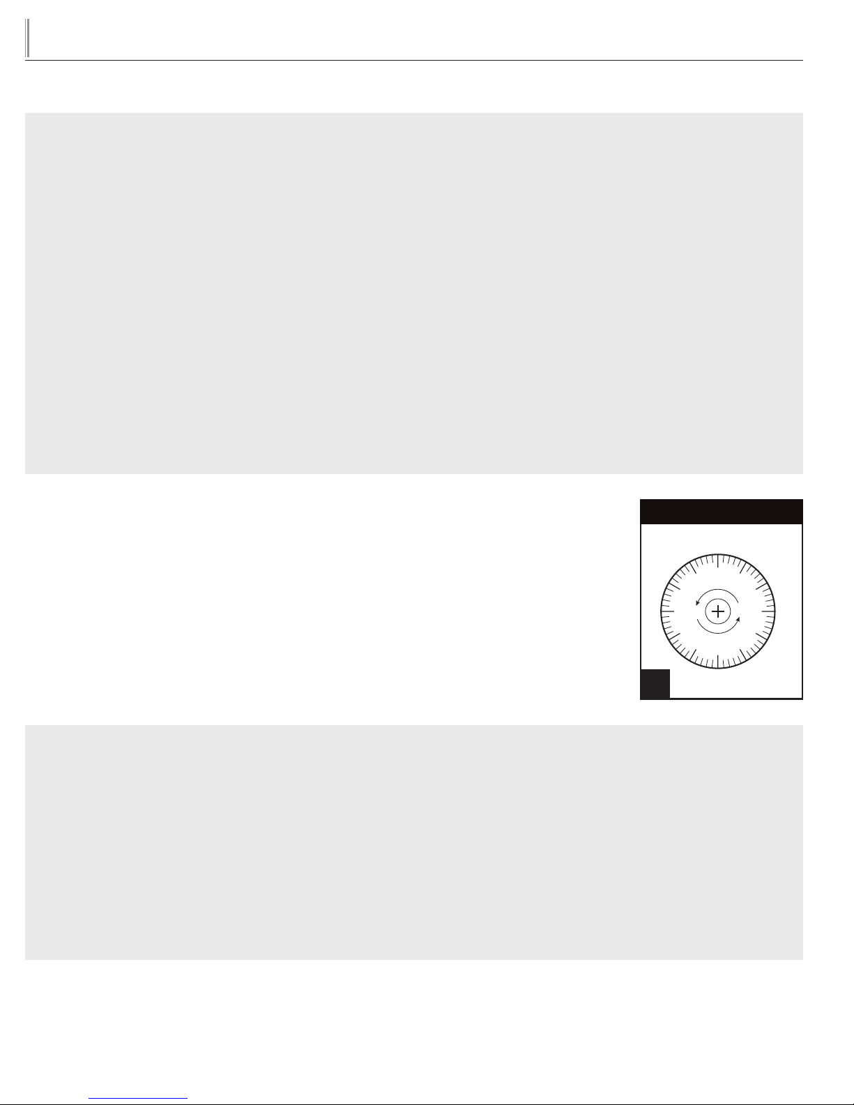
The scale to the right may be used as a guide for measuring degrees of rotation required for
altitude correction. The arrows indicate direction of screw rotation. See Figure 1.
IMPORTANT: Upright models ordered with “High Altitude” temperature controls are
pre-calibrated and do not require adjustment.
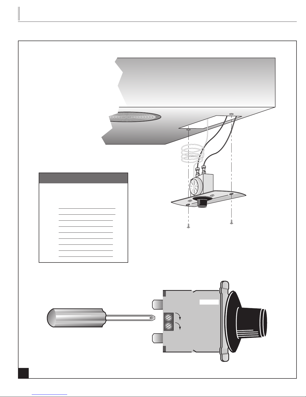
INSTRUCTIONS: CUTLER HAMMER TEMPERATURE CONTROL ALTITUDE ADJUSTMENT
STEP 1 - Unplug cooler.
STEP 2 - Turn the temperature control to the “9” position.
STEP 3 - Remove the screws that secure the mounting plate to the evaporator top. See Figure 2.
Scale Guide for Measuring
360
90
270
180
1
STEP 4 - Pull control down gently from housing.
STEP 5 - Turn screws counterclockwise (CCW).
STEP 6 - Reassemble to cooler housing and return the temperature control to the “5” position.
11
Page 13
TRUE
O
9
8
7
6
5
4
3
2
1
tgu/tgw
www.truemfg.com
CHART
CCW Adjustment
(based on 360°/
complete turn)Height
2000' 42°
3000' 78°
4000' 114°
5000' 150°
6000' 186°
7000' 222°
8000' 258°
9000' 294°
10,000' 330°
CUT
CUT
OUT
IN
BUL. NO.
COLDER
O
1
9
2
8
3
7
4
5
2
12
Page 14
TRUE
tgu/tgw
DEFROST CONTROLS
TIME INITIATED, TIME TERMINATED
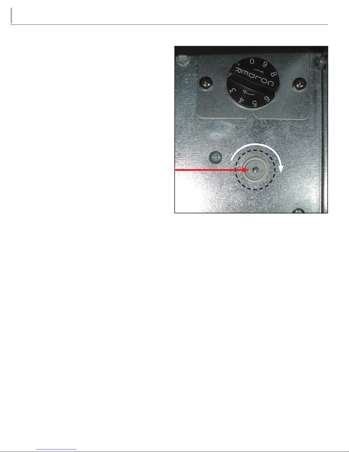
Timer Location: Defrost timer can be found directly below the
mechanical temperature control.
To adjust the defrost cycle time there is only one possible adjustment;
Once the cabinet has reach the design temperature, pick the time
of the day that you want the unit to defrost. Turn the actuating gear
clockwise until the contacts change position initiating the defrost
cycle. The next defrost cycle will occur 6-8 hours later, depending
upon model.
www.truemfg.com
13
Page 15
TRUE
tgu/tgw
www.truemfg.com
ELECTRONIC TEMPERATURE CONTROLS
LAE ELECTRONIC TEMPERATURE CONTROL GENERAL SEQUENCE OF OPERATION
t1 = Thermostat
t2 = Defrost
t3 = Display
t3 probe is not installed and / or activated in all applications
when t3 is not installed and / or activated, the display probe is t1.
LAE ELECTRONIC CONTROL GENERAL SEQUENCE OF OPERATION
1. Cabinet is plugged in.
a. Display will illuminate.
b. Interior light will illuminate on Glass Door Models only. Solid door cabinet lights are controlled by the door switch.
2. After the LAE control preprogrammed time delay of up to 6 minutes, the compressor and evaporator fan(s) will start if the
control is calling for cooling.
a. Control or condenser fans may be already pre-programmed from the factory so at the star t of every compressor cycle or
during a defrost cycle, the condenser fan(s) will reverse for 30 seconds to blow dirt off the condensing coil.
3. The LAE control will cycle the compressor but may also cycle evaporator fan(s) on and off determined by the Set-Point and
Differential temperatures.
a. The Set-Point is the adjustable preprogrammed temperature which shuts off the compressor and evaporator fan(s).
This is not the programmed cabinet temperature.
b. The Differential is the non adjustable preprogrammed temperature that is added to the Set-Point temperature that will
restart the compressor and evaporator fan(s).
c. The LAE control is designed to read and display a cabinet temperature not a product temperature.
This cabinet temperature may reflect the refrigeration cycle of the Set-Point and its Differential, or it may show an
average temperature.
The most accurate temperature on a cabinets operation is to verify the product temperature.
Example: If the Set-Point is -9°F/-23°C and the Differential is 10°F/5°C
The compressor and evaporator fan(s) will cycle off -9°F/-23°C and back on at 1°F/-18°C
4. The L AE control may be preprogrammed to initiate defrost by interval or at specif ic times of day.
a. At this time the “dEF” will appear on the display and compressor will turn off until a preprogrammed temperature or
duration is reached. During this time for freezers only, evaporator fan(s) will also turn off and the coil heater and drain tube
heaters will also be energized. Some cabinets may also change the rotation of the reversing condenser fan motor.
b. Af ter the preprogrammed temperature or duration for defrost has been reached there may be a short delay for both the
compressor and evaporator fans to restart. At this time “dEF” may still appear on the display for a short time.
(Set-Point) -9°F + 10 (Differential) = 1°F
Or
(Set-Point) -23°C + 5 (Differential) = -18°C
14
Page 16
TRUE
tgu/tgw
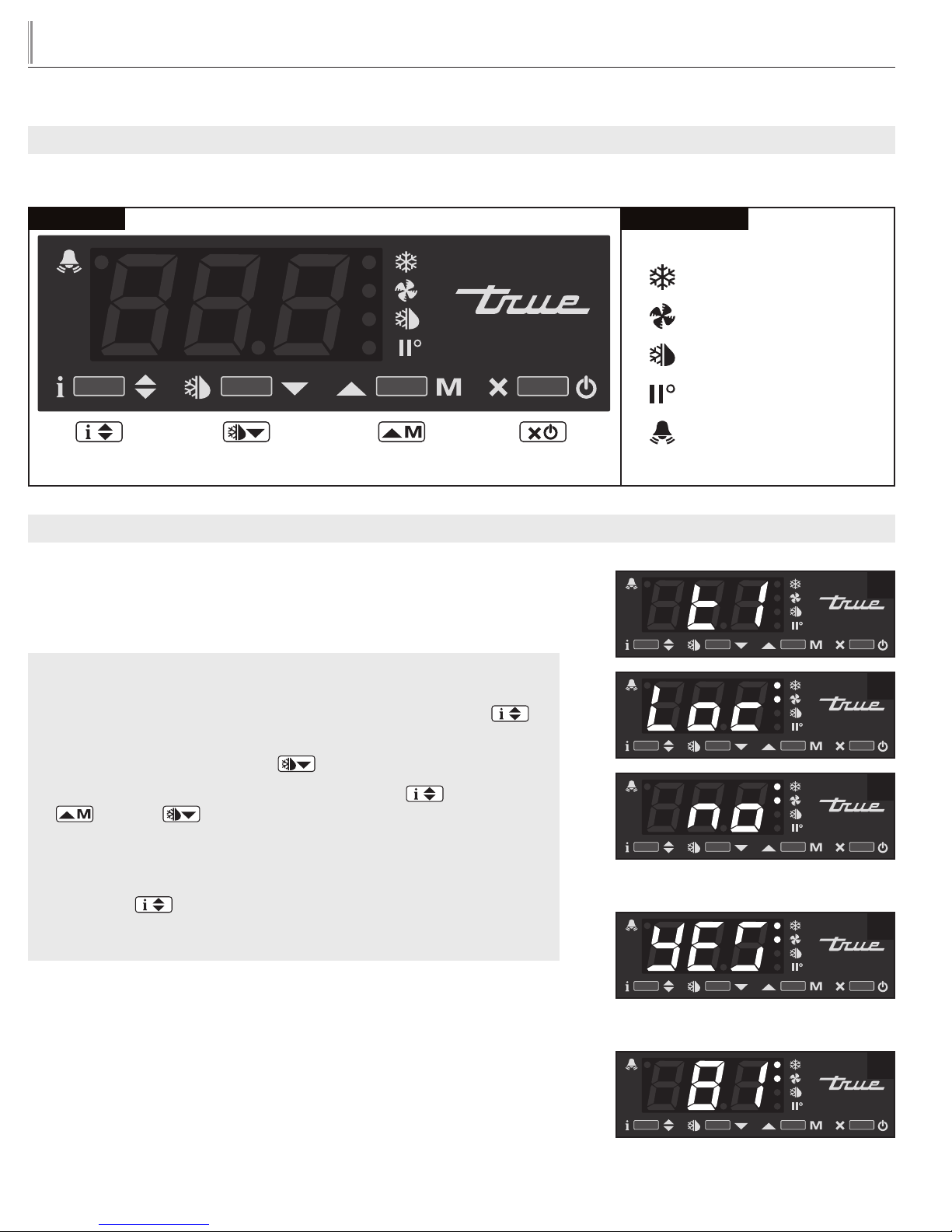
HOW TO DIAGNOSE AN LAE ELECTRONIC CONTROL
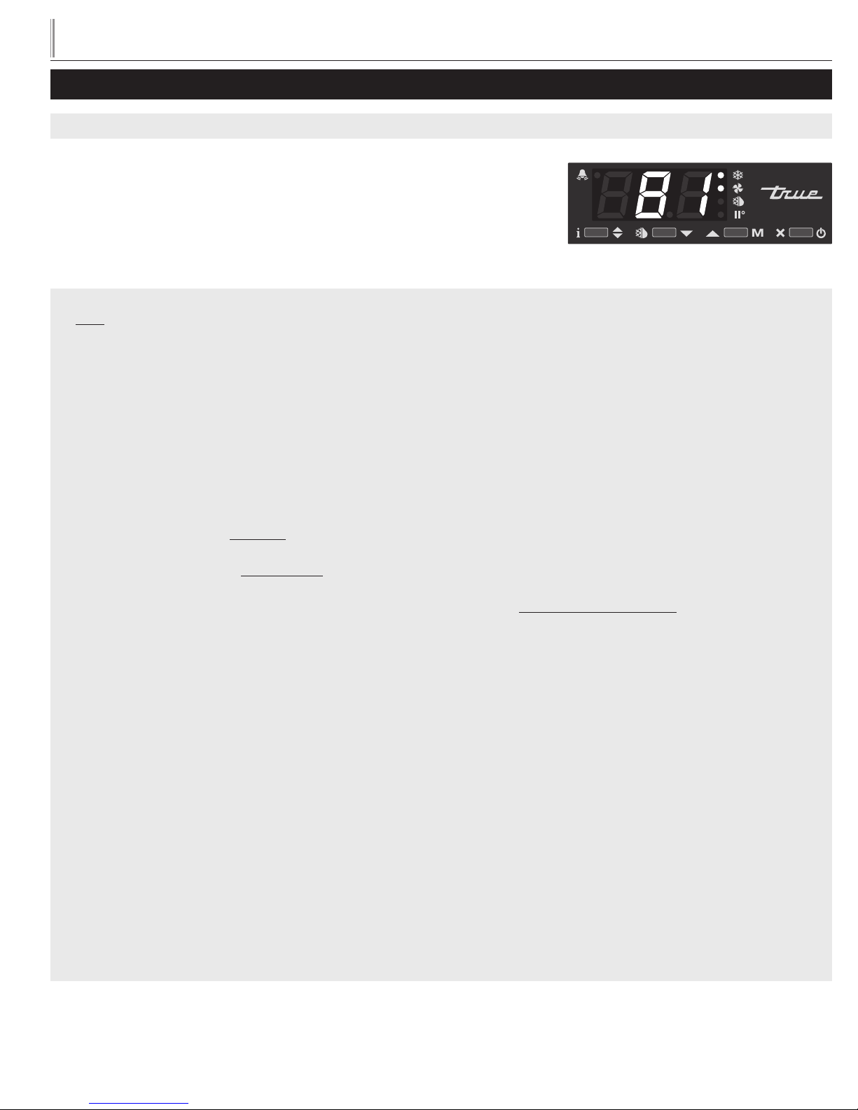
Indicator lights for Refrigeration/Heating Mode, Fan Operation, Defrost Mode.
www.truemfg.com
LAE Control
Info / Set Point
Button
USING THE LAE ELECTRONIC CONTROL
LOCKING AND UNLOCKING THE LAE CONTROLLER:
WHY: Locking of control is necessary to prevent changes to program that may affect
cabinet operation.
Manual Defrost /
Down Button
Manual Activation
Up Button
Stand- By
Button
LAE Control Icons
Compressor Running
Evaporator Fan Running
Cabinet in Defrost
Activation of 2nd Parameter Set
Alarm
1
HOW TO LOCK AND UNLOCK LAE CONTROLLER:
STEP 1 - To change lock setting press and release the Info button .
“t1” will appear. See image 1.
STEP 2 - Press the Down button until “Loc” appears. See image 2.
STEP 3 - While pressing and holding the Info button press the Up
or Down button to change the lock settings. If “no” appears,
the controller is unlocked. If “yes” appears, the controller is locked. See
images 3 and 4.
STEP 4 - Once the lock setting has been set correctly release the
info button . Wait 5 seconds for the display to show temperature.
See image 5.
2
3
Image 3: If “no” appears on screen,
the controller is unlocked.
4
Image 4: If “yes” appears on screen, the
controller is locked.
5
15
Page 17
TRUE
tgu/tgw
LAE Control
www.truemfg.com
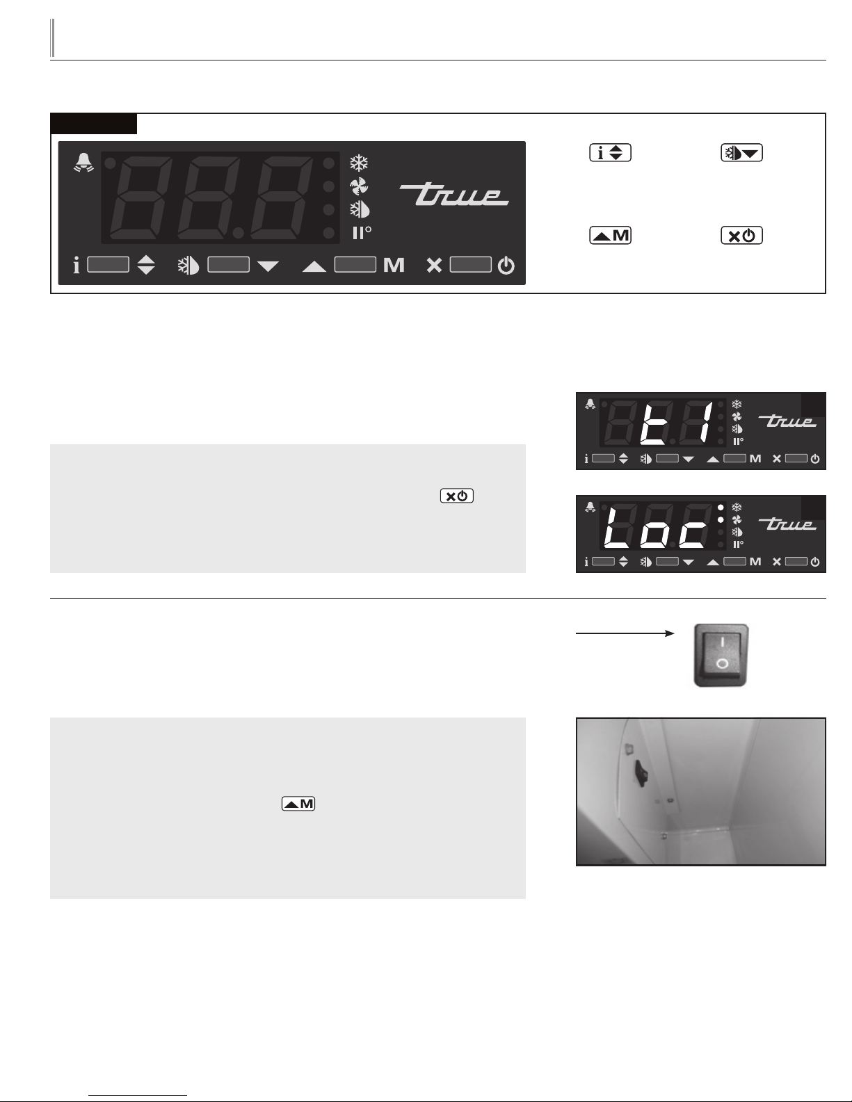
HOW TO TURN OFF THE LAE ELECTRONIC CONTROL:
May need to unlock control.
WHY: Turning off the control will deactivate all electrical components.
CAUTION: Turning off the control will not shut off power to the cabinet. Cabinet
must be unplugged prior to any repair.
HOW TO TURN OFF THE LAE ELECTRONIC CONTROL:
STEP 1 - To turn off control, press and hold the Stand-by button until
"OFF" appears. Release Stand-by button. See Image 2.
STEP 2 - To turn on control, repeat prior steps and a temperature will appear.
Info / Set Point
Button
Manual Activation
Up Button
Manual Defrost /
Down Button
Stand- By
Button
1
2
TURNING THE GLASS DOOR MODEL LIGHTS ON AND OFF:
May need to unlock control.
WHY: Light may be controlled by LAE Controller or interior light switch.
HOW TO TURN THE GLASS DOOR MODEL LIGHT ON
AND OFF:
STEP 1 - To control interior / sign lights by the LAE Controller, press and
release the Manual Activation button .
STEP 2 - To control interior / sign lights by the interior door switch, depress
the rocker switch to the “ON” position. Light switch is located on inside top
right of the ceiling.
ON Position
(Solid Door model lights are controlled by a
door switch)
16
Page 18
TRUE
tgu/tgw
LAE Control
www.truemfg.com
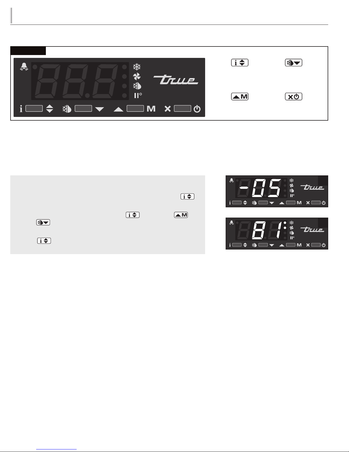
CHANGING THE "SET POINT":
May need to unlock control.
WHY: The set point is the temperature at which the compressor will shut off.
NOTE: The “set point” IS NOT the cabinet holding temperature.
HOW TO CHANGE THE “SET POINT”:
STEP 1 - To see the set point, press and hold the Info button .
See image 1.
STEP 2 - While still holding the Info button , press the Up or
Down button to change the “set point”.
STEP 3 - Once the “set point” has been set correctly release the Info
button . The display will show temperature. See image 2.
Info / Set Point
Button
Manual Activation
Up Button
Manual Defrost /
Down Button
Stand- By
Button
1
2
17
Page 19
TRUE
tgu/tgw
LAE Control
www.truemfg.com
Info / Set Point
Button
Manual Activation
Up Button
Manual Defrost /
Down Button
Stand- By
Button
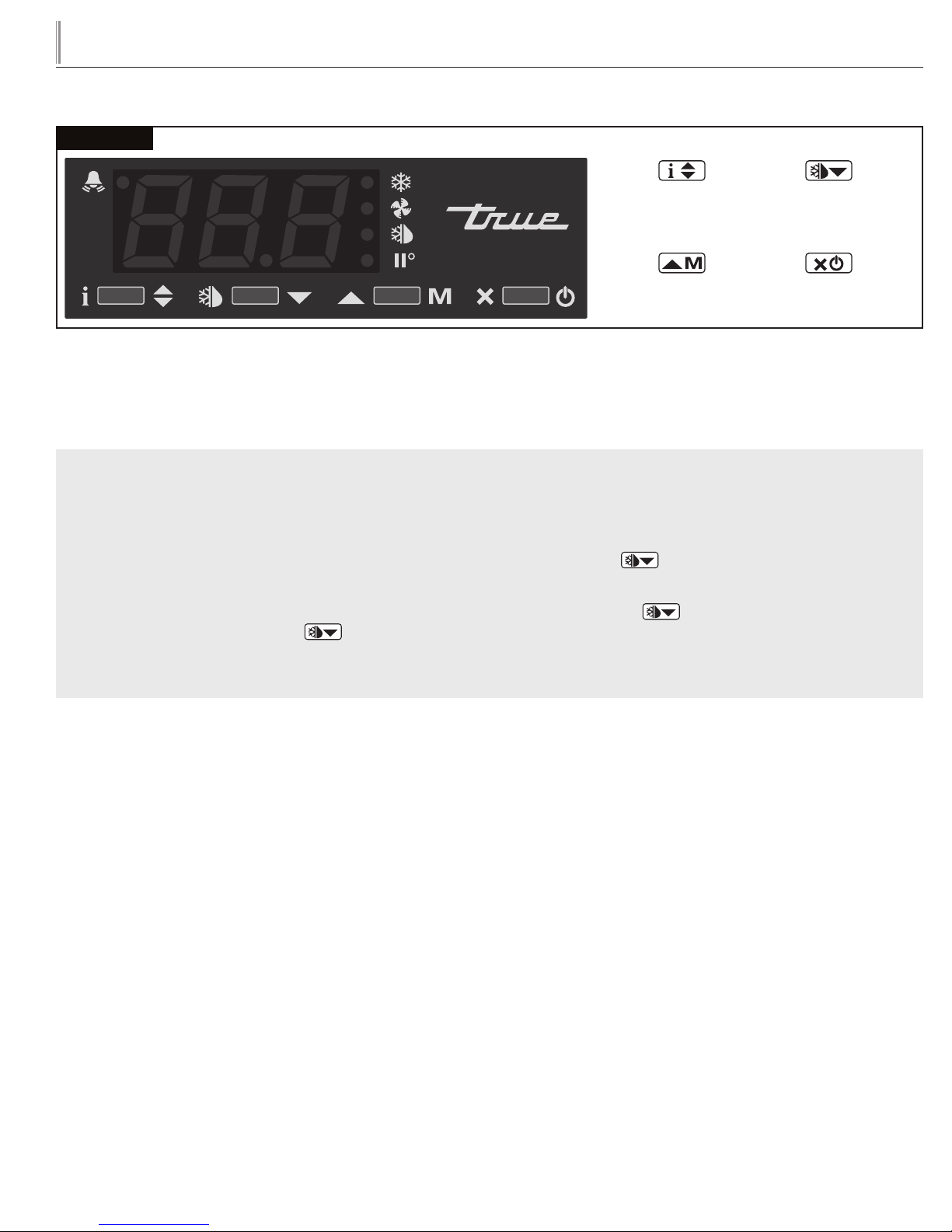
INITIATE A MANUAL DEFROST:
May need to unlock control.
WHY: A one time additional defrost may be necessary to clear accumulated frost / ice from evaporator coil.
HOW TO INITIATE A MANUAL DEFROST:
The method to initiate a manual defrost is determined by the Defrost Mode Parameter “DTM” preprogrammed in the controller.
REGULAR TIME DEFROST (TIM)
If controller is preprogrammed for “TIM”, press and release the Manual Defrost button until “dEF” appears.
REAL TIME CLOCK (RTC)
If controller is preprogrammed for “RTC” press the and hold the Manual Defrost button for 5 seconds until “dh1” appears.
Release the Manual Defrost button and then press and hold for an additional 5 seconds until “dEF” appears.
NOTE: Defrost will only terminate once a specific preset temperature or a preset time duration is reached.
18
Page 20
TRUE
tgu/tgw
LAE Control
www.truemfg.com
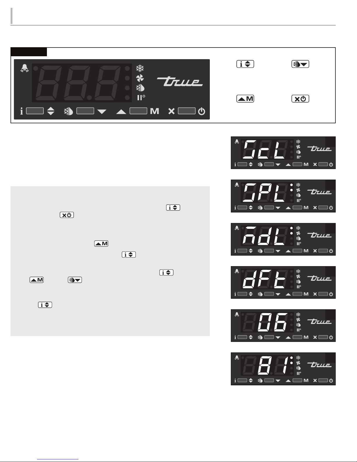
CHANGING “DEFROST INTERVALS”:
May need to unlock control.
This can only be changed if defrost mode parameter “DFM” is set for “TIM”.
WHY: The defrost interval is the time duration between defrost cycles. The defrost
interval time starts when the cabinet is supplied power or after a manual defrost.
HOW TO CHANGE “DEFROST INTERVALS":
STEP 1 - To see the set point, press and hold the Info button and the
Stand-by button at the same time.
NOTE: Depending on the version of control, one of three parameters will
appear: “ScL” image 1a, “SPL” image 1b, “MdL” image 1c.
Info / Set Point
Button
Manual Activation
Up Button
Manual Defrost /
Down Button
Stand- By
Button
1a
1b
1c
STEP 2 - Push the Up button until “dFt” appears. See image 2.
STEP 3 - Press and hold the Info button to see the defrost interval
time. See image 3.
STEP 4 - While pressing and holding the Info button , press the
Up or Down button to change the defrost interval times (higher
the number the less frequent the cabinet will defrost).
STEP 5 - Once the defrost interval time has been changed, release the Info
button .
STEP 6 - Wait 30 seconds for the display to show temperature.
See image 4.
2
3
4
19
Page 21
TRUE
tgu/tgw
LAE Control
www.truemfg.com
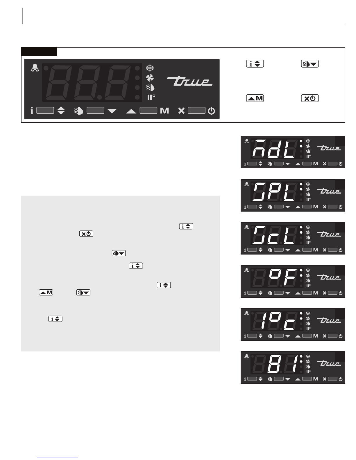
HOW TO CHANGE DISPLAY READOUT FROM
FAHRENHEIT TO CELSIUS:
May need to unlock control.
This can NOT be changed with the LAE model AR2-28 version of the control. See
page 32 for more information.
WHY: Changing readout will assist with customer application.
HOW TO CHANGE DISPLAY READOUT FROM
FAHRENHEIT TO CELSIUS:
STEP 1 - To change the display, press and hold the Info button and
the Stand-by button at the same time. “MdL” or “SPL” will appear.
See images 1a and 1b.
Info / Set Point
Button
Manual Activation
Up Button
Manual Defrost /
Down Button
Stand- By
Button
1a
1b
2
STEP 2 - Push the Down button until “ScL” appears. See image 2.
STEP 3 - Press and hold the Info button to see the “readout scale”.
See image 3.
STEP 4 - While pressing and holding the Info button , press the
up or down button to change the “readout scale".
See image 4.
STEP 5 - Once the “readout scale” has been changed, release the info
button .
STEP 6 - Wait 30 seconds for the display to show temperature.
See image 5.
3
4
5
20
Page 22
TRUE
tgu/tgw
LAE Control
www.truemfg.com
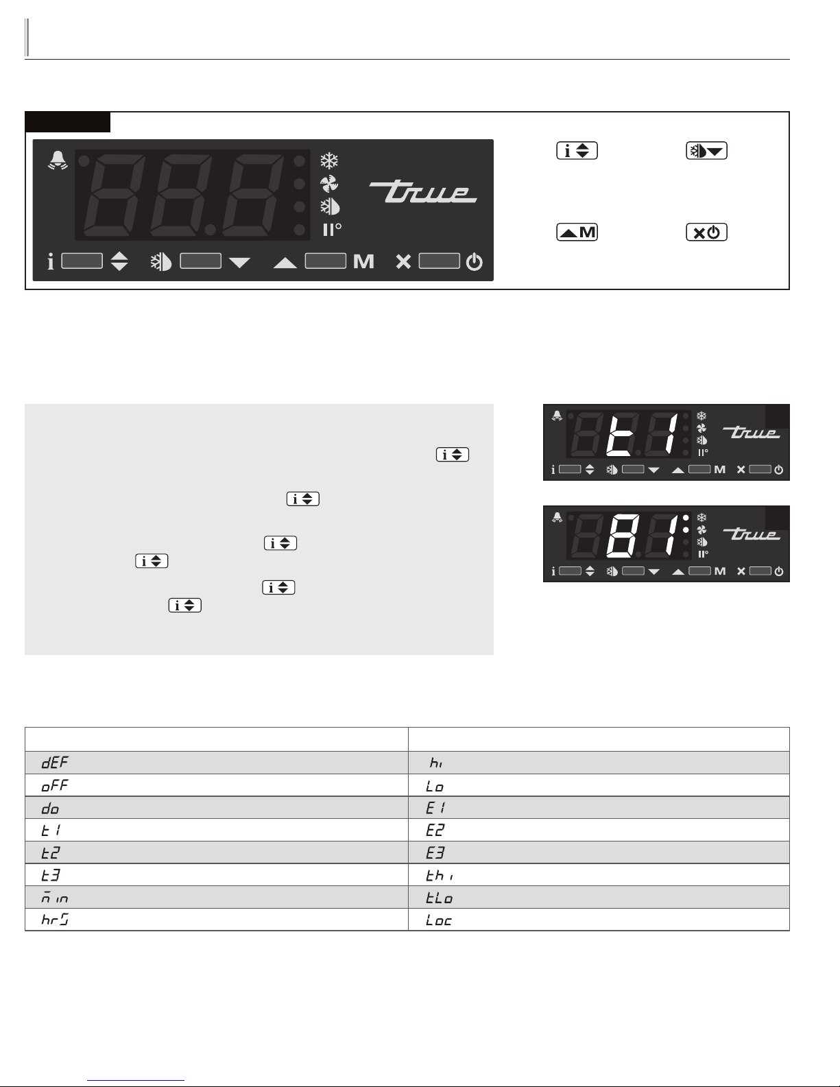
DISPLAYING TEMPERATURE PROBES, T1, T2, T3:
WHY: To display temperature probe readings in different locations of the cabinet.
HOW TO DISPLAY PROBE TEMPERATURES:
STEP 1 - To display T1 temperature, press and release the info button
. “t1” will appear. See image 1.
STEP 2 - Press and hold the info button . This is the temperature of
the T1 Probe. See image 2.
STEP 3 - By releasing the info button , “t2” will appear. Press and hold
the info button to display the temperature of the T2 probe.
Info / Set Point
Button
Manual Activation
Up Button
Manual Defrost /
Down Button
Stand- By
Button
1
2
STEP 4 - By releasing the info button again, “t3” will appear. Press and
hold the info button to display the temperature of the T3 probe. (If
probe T3 is not activated, “t3” will not appear of the display.)
DISPLAY CODES
DISPLAY
Defrost in progress Room high temperature alarm
Controller in stand-by Room low temperature alarm
Door open alarm Probe T1 failure
Instant Probe 1 temperature Probe T2 failure
Instant Probe 2 temperature Probe T3 failure
Instant Probe 3 temperature Maximum probe 1 temperature recorded
Minutes of the Real Time Clock Minimum probe 1 temperature recorded
Hours of the Real Time Clock Keypad state lock
21
Page 23
TRUE
SUBJECT TO CHANGE
tgu/tgw
www.truemfg.com
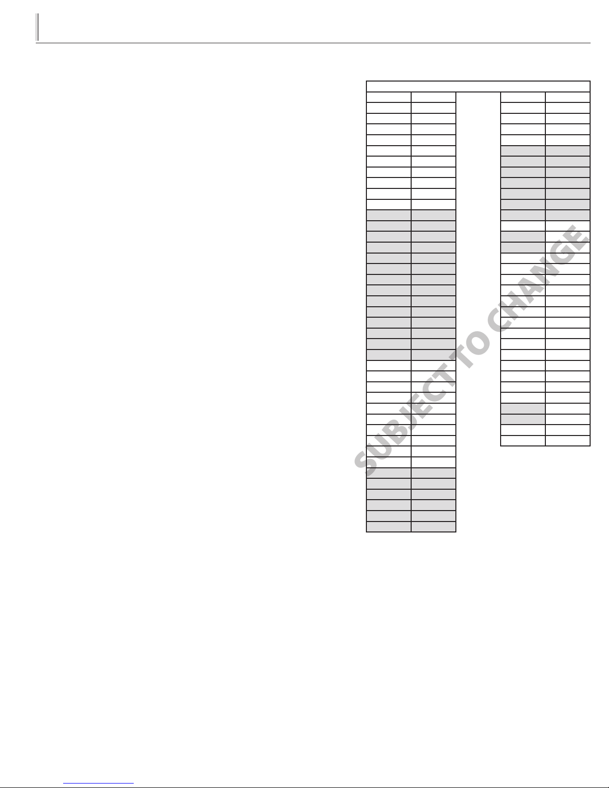
LAE CONTROLLER PARAMETER SETTINGS FOR CELSIUS
For LAE control model AR2-28 ONLY, ALL parameters with a formula
shown need to be converted for Celsius applications.
EXAMPLE:
If current SPL is set for 20 degrees F the formula is (X-32) / 1.8
(20-32) / 1.8 = -6.7 Celsius
AR2-28
SCL 1C ADO
SPL (X-32) / 1.8 AHM
SPH (X-32) / 1.8 AHT (X-32) / 1.8
SP (X-32) / 1.8 ACC
C-H IISM
HYS (X) / 1.8 IISL (X-32) / 1.8
CRT IISH (X-32) / 1.8
CT1 IISP (X-32) / 1.8
CT2 IIHY (X) / 1.8
CSD IIFC
DFM HDS
DFT IIDF
DH1 SB
DH2 DS
DH3 DSM
DH4 DI2
DH5 STT
DH6 EDT
DLI (X-32) / 1.8 LSM
DTO OA1
DTY OA2
DPD CD
DRN INP
DDM OS1 (X) / 1.8
DDY T2
FID OS2 (X) / 1.8
FDD (X-32) / 1.8 T3
FTO OS3 (X) / 1.8
FCM TLD
FDT (X) / 1.8 TDS
FDH (X) / 1.8 AVG
FT1 SIM
FT2 ADR
FT3
ATM
ALA (X-32) / 1.8
AHA (X-32) / 1.8
ALR (X) / 1.8
AHR (X) / 1.8
ATI
ATD
22
Page 24
TRUE
tgu/tgw
MAINTENANCE, CARE, CLEANING
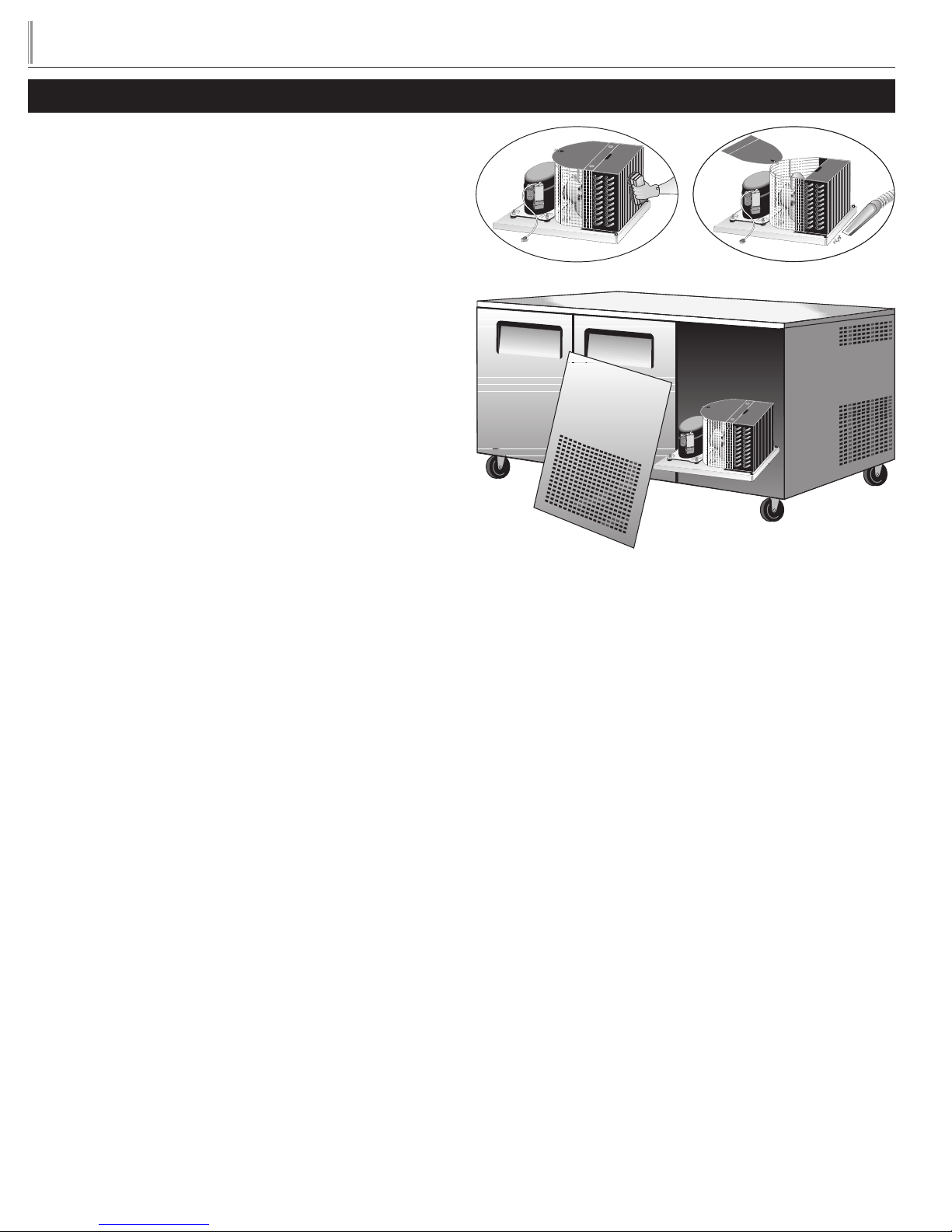
CLEANING THE CONDENSER COIL
When using electrical appliances, basic safety precautions should be
followed, including the following:
TOOLS REQUIRED
www.truemfg.com
• Phillips Screwdriver
• Stiff Bristle Brush
• Adjustable Wrench
STEP 1 - Disconnect power to unit.
STEP 2 - Remove the four Phillips screws to allow removal of the
front grill.
STEP 3 - Remove bolts anchoring compressor assembly to frame
rails and carefully slide out. (Tube connections are flexible)
STEP 4 - Clean off accumulated dirt from condensing coil with a
stiff bristle brush.
STEP 5 - Lift cardboard cover above fan at plastic plugs and carefully
clean condenser coil and fan blades.
STEP 6 - After brushing condenser coil vacuum dirt from coil, and
interior floor.
STEP 7 - Replace cardboard cover. Carefully slide compressor
assembly back into position and replace bolts.
STEP 8 - Reinstall louver assembly onto unit with appropriate
fasteners and clips. Tighten all screws.
STEP 9 - Connect unit to power and check to see if condenser is
running.
• Air Tank or CO2 Tank
• Vacuum Cleaner
23
Page 25
TRUE
Condenser
tgu/tgw
www.truemfg.com
IMPORTANT WARRANTY INFORMATION
Condensers accumulate dirt and require cleaning every 30 days.
Dirty condensers result in compressor failure, product loss, and lost
sales, which are not covered by warranty.
If you keep the Condenser clean you will minimize your ser vice
expense and lower your electrical costs. The Condenser requires
scheduled cleaning every thir ty days or as needed.
Air is pulled through the Condenser continuously, along with dust,
lint, grease, etc.
A dirty Condenser can result in NON-WARRANTEED part &
Compressor Failures, Product Loss, and Lost Sales.
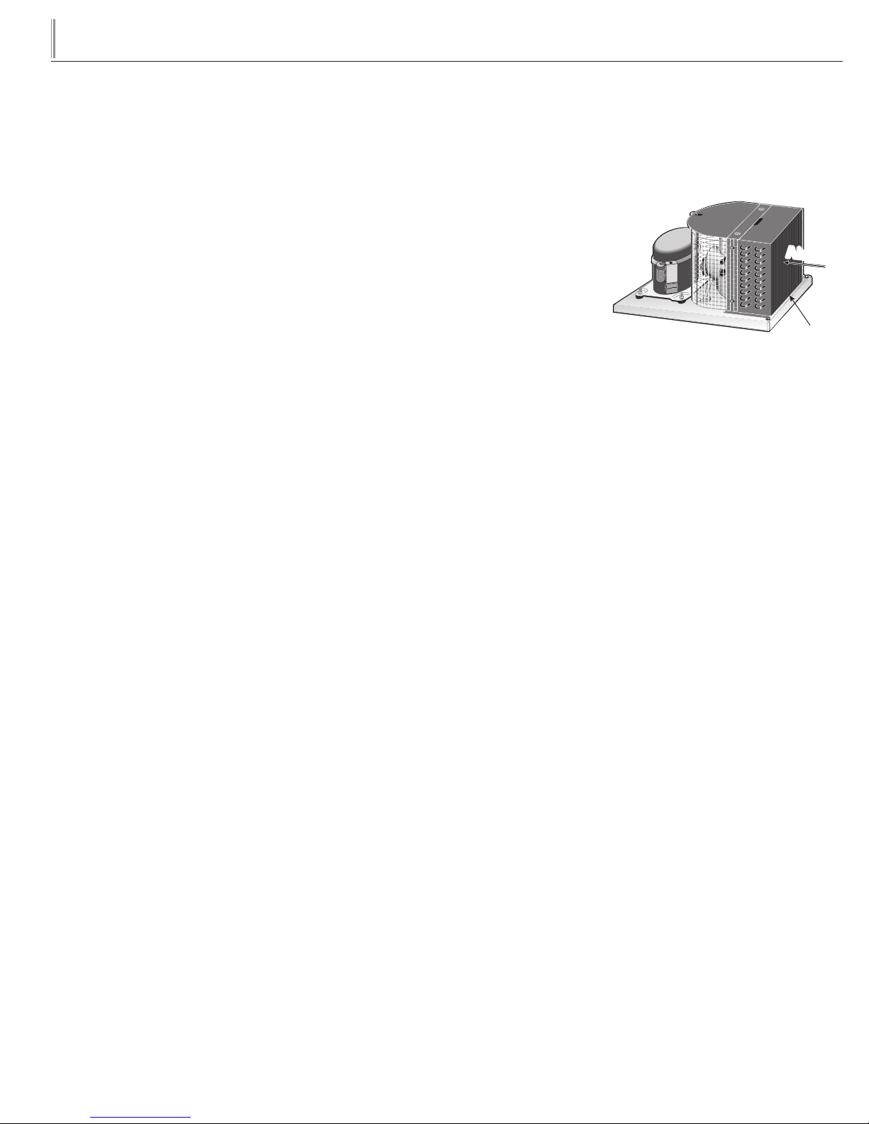
Proper cleaning involves removing dust from the Condenser. By using
a soft brush, or vacuuming the Condenser with a shop vac, or using
CO2, nitrogen, or pressurized air.
If you cannot remove the dirt adequately, please call your refrigeration service company.
On most of the reach-in units the condenser is accessible in the
rear of the unit. You must remove the cabinet grill to expose the
Condenser.
The Condenser looks like a group of vertical fins. You need to be able
to see through the condenser for the unit to function at maximum
capacity. Do not place filter material in front of condensing coil. This
material blocks air-flow to the coil similar to having a dirty coil.
THE CLEANING OF THE CONDENSER IS NOT
COVERED BY THE WARRANTY!
HOW TO CLEAN THE CONDENSER:
1. Disconnect the
electrical power to
the unit.
2. Remove the louvered
grill.
3. Vacuum or brush the
dirt, lint, or debris
from the finned
condenser coil.
4. If you have a signif icant dir t build up you can blow out the
condenser with compressed air.
(CAUTION MUST BE USED TO AVOID EYE INJURY.
EYE PROTECTION IS RECOMMENDED.)
5. When finished be sure to replace the louvered grill. The grill
protects the condenser.
6. Reconnect the electrical power to the unit.
If you have any questions, please call TRUE Manufacturing at 636-2402400 or 800-325-6152 and ask for the Service Depar tment. Direct
to Service Department 1(855)372-1368. Service Department
Availability Monday-Thursday 7:00 a.m. to 7:00 p.m., Friday 7:00 a.m.
to 6:00 p.m. and Saturday 8:00 a.m. to 12:00 p.m. CST.
Condensing Unit
Airflow
24
Page 26

TRUE
tgu/tgw
www.truemfg.com
STAINLESS STEEL EQUIPMENT CARE
AND CLEANING
CAUTION: Do not use any steel wool, abrasive or chlorine based
products to clean stainless steel surfaces.
STAINLESS STEEL OPPONENTS
There are three basic things which can break down your stainless
steel’s passivity layer and allow corrosion to rear its ugly head.
1. Scratches from wire brushes, scrapers, and steel pads are just
a few examples of items that can be abrasive to stainless steel’s
surface.
2. Deposits left on your stainless steel can leave spots. You may have
hard or sof t water depending on what part of the country you live
in. Har d water can leave spot s. Hard water that is heated can leave
deposits if left to sit too long. These deposits can cause the
passive layer to break down and rust your stainless steel. All
deposits left from food prep or service should be removed as
soon as possible.
3. Chlorides are present in table salt, food, and water. Household
and industrial cleaners are the worst type of chlorides to use.
8 STEPS THAT CAN HELP PREVENT RUST ON
STAINLESS STEEL:
1. USING THE CORRECT CLEANING TOOLS
Use non-abrasive tools when cleaning your stainless steel
products. The stainless steel’s passive layer will not be harmed
by soft cloths and plastic scouring pads. Step 2 tells you how to
find the polishing marks.
2. CLEANING ALONG THE POLISH LINES
Polishing lines or “grain” are visible on some stainless steels.
Always scrub parallel to visible lines on some stainless steels.
Use a plastic scouring pad or soft cloth when you cannot see
the grain.
3. USE ALKALINE, ALKALINE CHLORINATED OR
NON-CHLORIDE CONTAINING CLEANERS
While many traditional cleaners are loaded with chlorides, the
industry is providing an ever increasing choice of non-chloride
cleaners. If you are not sure of your cleaner’s chloride content
contact your cleaner supplier. If they tell you that your present
cleaner contains chlorides, ask if they have an alternative. Avoid
cleaners containing quaternary salts as they can attack stainless
steel, causing pitting and rusting.
4. WATER TREATMENT
To reduce deposits, soften the hard water when possible.
Installation of certain f ilters can remove corrosive and distasteful
elements. Salts in a properly maintained water softener can be
to your advantage. Contact a treatment specialist if you are not
sure of the proper water treatment.
5. MAINTAINING THE CLEANLINESS OF YOUR
FOOD EQUIPMENT
Use cleaners at the recommended strength (alkaline chlorinated
or non-chloride). Avoid build-up of hard stains by cleaning
frequently. When boiling water with your stainless steel
equipment, the single most likely cause of damage is chlorides
in the water. Heating any cleaners containing chlorides will have
the same damaging effects.
6. RINSE
When using chlorinated cleaners you must rinse and wipe dry
immediately. It is better to wipe standing cleaning agents and
water as soon as possible. Allow the stainless steel equipment
to air dry. Oxygen helps maintain the passivity film on stainless
steel.
7. HYDROCHLORIC ACID (MURIATIC ACID)
SHOULD NEVER BE USED ON STAINLESS STEEL
8. REGULARLY RESTORE/PASSIVATE STAINLESS
STEEL
RECOMMENDED CLEANERS FOR CERTAIN
SITUATIONS / ENVIRONMENTS OF STAINLESS
STEEL
A. Soap, ammonia and detergent medallion applied with a cloth or
sponge can be used for routine cleaning.
B. Arcal 20, Lac-O-Nu Ecoshine applied provides barrier film for
fingerprints and smears.
C. Cameo, Talc, Zud First Impression is applied by rubbing in
the direction of the polished lines for stubborn stains and
discoloring.
D. Easy-off and De-Grease It oven aid are excellent for removals
on all finishes for grease-fatty acids, blood and burnt-on foods.
E. Any good commercial detergent can be applied with a sponge
or cloth to remove grease and oil.
F. Benefit, Super Sheen, Sheila Shine are good for restoration /
passivation.
NOTE: The use of stainless steel cleaners or other such solvents is
not recommended on plastic parts. Warm soap and water will suffice.
25
FOR ADDITIONAL MAINTENANCE INSTRUCTION,
PLEASE VISIT THE MEDIA CENTER AT
WWW.TRUEMFG.COM
 Loading...