

Page 1
TRUE
TECHNICAL SERVICE MANUAL - ALL MODELS
TEMPERATURE
CONTROLS/
THERMOMETER/TIMERS
www.truemfg.com
117
Page 2

NOTES
118
Page 3

TRUE
TECHNICAL SERVICE MANUAL - ALL MODELS
TEMPERATURE
CONTROLS/
THERMOMETER/TIMERS
www.truemfg.com
Temperature Control Repairs
119
Page 4
TRUE
SUBJECT TO CHANGE
TECHNICAL SERVICE MANUAL - ALL MODELS
HOW TO DIAGNOSE
www.truemfg.com
STEP 1 - Control must operate
within its pre-calibrated range of
temperatures.
STEP 2 - Cut-in is the ON tem-
perature.
STEP 3 - Cut-out is the OFF tem-
perature.
NOTE:
All temps are at mid-point
setting #5. All temps advised
have a +/- 2 degree variance.
Confirmed Calibration
TRUE P/N MFG P/N APPLICATION CUT-IN CUT OUT
800303 9531N376 35 15
800304 9530N1490 -9 -15
800306 9531N251 40 19
800312 9530N1284 -8 -15
800313 9531N335 37 16
800320 9530N1185 33 27
800325 9530N1318 RED WINE, CHOCOLATE 62 55
800335 9530N1376 38 20
800340 9530N1155 26 11
800345 077B1264 -3 -16
800357 9530266 -3 -8
800358 077B1214 -9 -14
800363 9530C311 -3 -13
800366 077B6806 37 17
800368 077B6857 42 23
800369 077B1212 -3 -12
800370 077B1216 -14 -25
800371 077B6863 42 24
800382 077B6856 37 18
800383 077B1227 0 -6
800384 077B1229 25 19
800385 077B1228 WHITE WINE 43 34
800386 077B6871 41 20
800387 077B6887 FLOWER COOLER 39 21
800390 9530N1329 SUPER NOVA 13 8
800393 077B6827 42 21
800395 931N370 HIGH ALTITUDE 40 23
800399 9530C304 0 -5
822212 CAP-075-174R HEATED
822213 077B6894 37 22
822214 077B1309 31 17
822223 077B1331 26 9
831931 077B1277 -2 -9
831932 3ART56VAA4 40 18
831987 077B0995 RED WINE, CHOCOLATE 57 50
908854 077B6926 36 10
908975 077B1352 -16 -32
911427 077B1354 38 26
913382 077B1367 -11 -23
917838 077B1369 0 -14
930794 091X9775 42 25
933190 091X9796 42 19
958745 3ART55VAA4 39 18
958747 095X0028 37
958857 3ART5VAA198 8 -6
959268 3ART55VAA3 40 26
960640 3ART55VAA5 43 20
962728 3ART55VAA6 42 20
963056 3ART55VAA2 39 16
120
Page 5
TRUE
TECHNICAL SERVICE MANUAL - ALL MODELS
www.truemfg.com
HOW TO CHECK THE CUT-IN AND CUT-OUT OPERATION OF A
TEMPERATURE CONTROL
OPERATION INSTRUCTIONS
Tools Required
• 1/4" Nut Driver of Socket
• Digital Thermometer of Equivalent
• Multi-Meter (Optional)
1
STEP 1 - Disconnect the power to the cabinet.
STEP 2 - Locate the temperature control and note its setting. The temperature control
should be set at mid-range, about 5.
NOTE: If the control was set to high (colder) this could be why the product is
freezing. Reset the control and check the cabinet operation in 24-48 hours. You
may have to use your multi-meter to check and see if the control has power and is
closing.
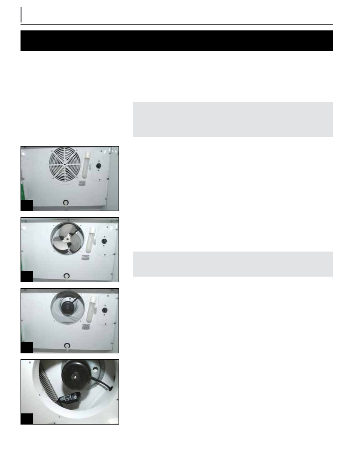
STEP 3 - Remove the four 1/4" hex head screws that secure the fan guard in place. This
will expose the evaporator motor fan blade. Keep in mind that there might be more than
one evaporator fan motor.
STEP 4 - Remove the nut that holds the fan blade in place. See image 2.
STEP 5 - Remove the fan blade. If there are additional fan blades remove all. See image 3
STEP 6 - Insert your digital thermometer into the evaporator coil as close to the tem-
perature control copper tube as possible. This would be to the right side of the opening.
See image 4.
STEP 7 - Plug the unit in. The compressor should come on. The evaporator temperature
will come down very fast allowing you to see approximately what temperature the control
opened up and the compressor shut off. This is your cut-out point. Check this against the
spec’s for the control to determine if the operation is where is should be.
NOTE: This process should not take more than 10 minutes. If it does, there might
be a problem with the refrigeration system.
2
STEP 8 - Open up the cabinet door (s) to allow the warm air to come into the cabinet.
This will warm up your evaporator coil and close the temperature control, turning the
compressor on. This is your cut-in point. Check this against the spec’s for the control to
determine if the operation is where it should be.
THE TEMPERATURES THAT YOU READ COULD BE + 2˚ F.
STEP 9 - Based on your ndings you may have to replace or adjust the control Repeat
Steps 7 and 8 several times to verify the operation after you have made the necessary
3
repairs.
STEP 10 - Remove the power cord. Starting with Step 5 and working backwards place
the fan blade and fan guard in place and put the unit back together.
STEP 11 - Plug the unit back in.
Most of the cooler temperature controls are
coil sensing constant cut-in controls.
4
121
Page 6

TRUE
TECHNICAL SERVICE MANUAL - ALL MODELS
www.truemfg.com
REPLACING TEMPERATURE CONTROLS IN GDM-7, GDM-10, AND
GDM-12 MODELS (OLD MODELS)
INSTALLATION INSTRUCTIONS
STEP 1 - Unplug Cooler and turn temperature control to “off ”
(“0”) position.
STEP 2 - Pull off the black control knob from the control.
STEP 3 - Remove the mounting plate from the evaporator housing.
STEP 4 - Remove the temperature control from the plate and dis-
connect the 2 wires.
STEP 5 - Remove the lamp from the front of the cooler and remove the front panel.
STEP 6 - Reach in to the side of the evaporator coil and remove
the permagum from around the control bulb. Then remove the old
thermostat control bulb from the sleeve completely.
STEP 7 - Insert the new thermostat control bulb into the new
copper sleeve extension until about 1/2 inch protrudes from the
swaged end. Using a low temperature lubricant on the control bulb
is advisable.
STEP 8 - Using the protruding end of the control bulb as a guide,
insert it into the copper sleeve (elbow) in the rear of the evaporator.
Then push the sleeve extension over the end of the elbow to lock
the two tubes together.
STEP 9 - Gently push the control bulb through the joined sleeves
in 1-2 inch increments until it reaches the end inside the evaporator,
taking care not to kink the line.
STEP 10 - Seal both ends of the new control sleeve with permagum
to keep moisture out.
STEP 11 - Remove the mounting plate from the evaporator housing.
Connect the 2 wires to the new control, the control to the mounting
plate, the plate to the cooler, and replace the control knob.
STEP 12 - Turn the control knob to the #5 setting.
STEP 13 - Reassemble front of cooler and plug it in.
FRONT OF COOLER
Temperature
Control
New Copper Sleeve
Extension
EVAPORATOR
Standard
Copper
Sleeve
Permagum
122
Page 7
TRUE
TECHNICAL SERVICE MANUAL - ALL MODELS
www.truemfg.com
TEMPERATURE CONTROL REPLACEMENT (FOR GDM & T-SERIES FREEZER
CABINETS WITH LARGER THAN 1/3 H.P. COMPRESSORS)
INSTALLATION INSTRUCTIONS
STEP 1 - Removing Power: Disconnect power to the unit.
WARNING:
Failure to disconnect power
to the unit may result in
electrocution to eld personnel.
STEP 2
Slide Door
Remove Louvered Grill:
WITH DANFOSS CONTROL.
Swing Door
Remove Louvered Grill:
Qualied Repair Personnel
• These repairs should be performed by a
qualied service technician.
Tools Required
• Phillips-head Bit
• 1/4" Nut Driver Bit
• Wire Cutters
• Drill
• Needle-Nose Pliers
• Wire Strippers
• Crimping Tool
• Voltmeter
• Plastic Mallet or Hammer
• Slotted Screwdriver
Contents of Relay Kit
• Relay (and mounting screws)
• Relay Shield (and mounting screws)
• (4) Relay wires: 2 blacks, 1 pink, 1 white
with insulated female spade connectors
on one end.
• Grommet
• (4) Sta-con connectors
• New temperature control
• Instructions
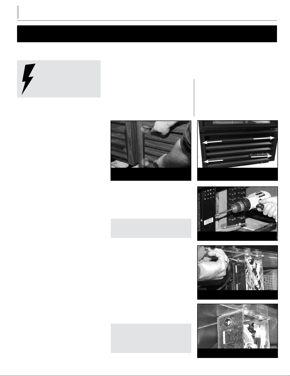
A. To remove grill, loosen upper screw
on each end of grill and remove lower
screws. Gently swing grill forward and up.
1a - Removing louvered grill
(slide door model)
STEP 3 - Accessing Wire Connections:
A. Remove ballast box cover by back-
ing out two hex head screws. (See
Image 2).
NOTE: Wiring diagram is positioned
on inside cover.
STEP 4 - Relay Connection Mounting:
A. With slotted screw driver and plastic
mallet or hammer, drive out knock out
positioned on left side of ballast box.
(See Image 3).
B. Install the supplied grommet* into the
knockout hole. (See Image 4).
C . Mount relay to underside of unit
on the left side of ballast box, and
3/4" back from the front edge of the
underside.
NOTE: Mount relay next to the ballast box, so that when the relay shield
is installed it covers the relay and all
exposed wiring.
A. Remove screws as indicated by ar-
rows.
1b - Removing louvered grill
(swing door model)
2 - Removing ballast box cover
3 - Driving out knockout
4 - Installing the grommet
123
Page 8

TRUE
TECHNICAL SERVICE MANUAL - ALL MODELS
www.truemfg.com
Relay should be anchored with two self-tapping screws, (supplied in kit), as pictured in
Image 5.
STEP 5 - Relay Temperature Control Wiring:
A. Connect the wires included in kit to the relay as follows:
1. Connect one black wire to one of the normally open contacts of the relay.
2. Connect the other black wire to the other normally open contact on the relay.
5 - Anchoring relay
6 - Relay wiring diagram
7 - Routing relay wires
3. Connect the pink wire to one side of the relay coil.
4. Connect the white wire to the other side of the relay coil.
NOTE: Each relay has a wiring diagram on the side of it. (See Illustration 6).
B. Feed wires into the ballast box through the knockout. (See Image 7).
C . Using the Sta-Con connectors in the relay kit, make the following connections inside
the ballast box:
1. Locate the pink wire coming from the temperature control and connecting to
the black compressor receptacle wire. Cut this connection and connect this pink
wire from the temp control to the pink wire going to the relay.
2. Connect one black wire on relay to the black wire cut from the compressor
receptacle.
3. Connect the white wire coming from the relay to the white wire bundle that is
connected to the white on the main power cord.
4. Connect one black wire to the black wire bundle that is connected to the outgoing terminal on the main power switch located on the ballast box.
STEP 6 - Replace existing temperature control with new Danfoss control in repair kit:
(See Image 8).
8 - Temperature control leads
124
A. Connect one pink wire from old control to terminal #4 on new temperature con-
trol.
B. Connect other pink wire from old control to terminal #3 on new Danfoss tempera-
ture control.
Page 9

TRUE
TECHNICAL SERVICE MANUAL - ALL MODELS
STEP 7 - Anchor the Relay Shield: (See Image 9).
A. Secure the new relay by attaching the relay shield.
B. Relay shield includes two self-tapping screws. When installing shield, place shield in
position to cover relay and all exposed wiring.
STEP 8 - Checking Relay Operation:
A. Unplug the condensing unit from the compressor receptacle ( located on the ballast
box).
B. Turn the new control to the “0”, (zero), position by aligning the zero indication on
control knob with the arrow stamped into the evaporator housing. Ensure that control is off by listening for an audible click. This will indicate an off position.
C . Plug voltmeter into compressor receptacle.
D. Plug cabinet into power source.
www.truemfg.com
9 - Anchoring relay whield
Securing Ballast Box:
A. Reinstall ballast box cover.
B. Anchor cover with two screws.
C . Check voltage at compressor receptacle. Voltage should equal voltage at wall outlet.
D. If voltage is correct, turn temperature control to “0”, (zero).
E. Plug condensing unit cord back into the compressor receptacle.
STEP 9 - Replacing Louvered Grill:
A. Reinstall grill by reversing earlier procedure.
STEP 10 - Re-connect Power Cord.
STEP 11 - Return Temp Control to normal setting, and check cabinet operation.
125
Page 10

TRUE
TECHNICAL SERVICE MANUAL - ALL MODELS
www.truemfg.com
TMC-49/49D-S/58/58D-S TEMPERATURE CONTROL RELAY KIT
INSTALLATION INSTRUCTIONS
Tools Required
• Drill
• 7/16" Drill Bit
• Philips Screwdriver
• 1/4" Nut Driver
TEMPERATURE CONTROL RELAY KIT
INCLUDES (936481):
• (1) Temperature Control (822213)
• (1) Temperature Control Relay (800182)
• (1) Cover (890353)
• (1) Bushing (811209)
• (1) Pink Wire (800705)
• (1) White Wire (800706)
• (2) Black Wires (800720) All wires come
with insulated Sta-con connectors installed.
STEP 1 - Inspect the supplied temperature control relay kit for all its parts.
STEP 2 - Remove the power supply from the cabinet.
STEP 3 - Remove the louvered grill (bottom rear of the cabinet). Locate the electrical box
on the lower right hand side of the compressor compartment. The compressor compartment is at the bottom of the cabinet. Remove the cover to the electrical box. (See Image 1).
STEP 4 - Place the wires on the temperature control relay. The two black wires go on
terminals #4 and #6. The pink wire should go on terminal #1 and the white wire should
go on terminal #0.
STEP 5 - Secure the temperature control relay near the electrical box using two of the
screws that were supplied. Be sure to leave enough room to allow the cover to be put on.
(See Image 2).
STEP 6 - Drill a 7/16" hole in the end of the electrical box and place the plastic bushing in it.
STEP 7 - Locate the pink wire coming from the temperature control, which connects to
the black compressor receptacle wire. Cut this wire and connect the pink wire from the
temperature control relay to this pink wire. Be sure to run the wires through the hole that
was just drilled in the front of the electrical box.
STEP 8 - Connect one black wire from the relay (Normally open contact point), to the
black wire cut from the compressor receptacle. Be sure to run the wires through the hole
that was just drilled in the front of the electrical box.
• (4) Screws (830592)
• (4) White Wire Nuts (802143)
NOTE:
First, remove the power to the unit
STEP 9 - Connect the white wire coming from the temperature control relay to the
white wire bundle that is connected to the main power cord. Be sure to run the wires
through the hole that was just drilled in the front of the electrical box.
STEP 10 - Connect the lone black wire (Normally open contact point) to the black wire
bundle that is connected to the main power cord. Be sure to run the wires through the
hole that was just drilled in the front of the electrical box.
STEP 11 - Install the cover around the temperature control relay using the remaining two
screws. (See Image 3).
STEP 12 - Install the cover back on the electrical box.
STEP 13 - Plug the unit back in and check the operation of the temperature control.
STEP 14 - Reinstall the louvered grill.
1 2 3
126
Page 11

TRUE
TECHNICAL SERVICE MANUAL - ALL MODELS
www.truemfg.com
DANFOSS TEMPERATURE CONTROL REPLACEMENT FOR REFRIGERATORS &
FREEZERS
INSTALLATION INSTRUCTIONS
(FOR TPP, TUC, TWT, & TSSU CABINETS WITH LARGER THAN 1/3 H.P. COMPRESSORS)
WARNING:
Failure to disconnect power
to the unit may result in
electrocution to eld personnel.
Qualied Repair Personnel
These repairs should be performed by a
qualied service technician.
Tools Required
• Phillips-head Bit
• 1/4" Nut Driver Bit
• Wire Cutters
• Drill
• Needle-Nose Pliers
• Wire Strippers
• Crimping Tool
• Voltmeter
• Plastic Mallet or Hammer
STEP 1 - Removing Power - Disconnect power to unit.
NOTE: Step 2 and 3 are related to TSSU, TUC, and TWT-72 models only. All
other models go directly to Step 4.
STEP 2 - Removing shelving standards and I-beams (for TUC, TSSU, & TWT-72 only):
A. To remove side shelf standards back-out two plastic thumb screws on either side
of the cabinet (See Image 1a). Then back-out four 1/4" hex screws that support the
center I-beam in the rear of the cabinet (See Image 1b). Mark locations and positions of standards with tape for easly installation.
STEP 3 - Removing Evaporator Housing Cover (TUC, TSSU, & TWT-72).
A. Remove four slotted thumb screws with a standard screw driver. Then remove two
Phillips-head screws next to the temperature control knob. At this point all cabinets with pans (TSSU models) can have the pans removed for easier access to the
temperature control. Gently move the evaporator cover away from the rear of the
cabinet to reveal the temperature control. (See Image 2).
STEP 4 - Locating and removing temperature control (for all models):
A. The temperature control is inside the cabinet on the right-hand side. Back-out two
thumb screws holding the temperature control plate in place. (See image 3).
STEP 5 - Replace existing temperature control with new Danfoss control in repair kit:
A. Once the temperature control is revealed you can then disconnect the old tempera-
ture control (remove the control knob and then back out two phillips screws).
• Slotted Screwdriver
Contents of Relay Kit
• Relay (and mounting screws)
• Relay Shield (and mounting screws)
• (4) Relay wires: 2 blacks, 1 pink, 1 white
with insulated female spade connectors
on one end.
• Grommet
• (4) Sta-con connectors
• New temperature control
• Instructions
Kit Part Numbers
• #882635 for the TPP-93, TUC/TWT-93,
TSSU-72-18’s
• #882636 for the TSSU-72-30M-B’s
• #883552 for the TPP-119, TWT-119, TUC-119
B. Unplug control wiring from old control.
C . Pull control capillary out of 3/16" tubing inserted into coil.
1a
1b
2 3
127
Page 12

TRUE
TECHNICAL SERVICE MANUAL - ALL MODELS
4
www.truemfg.com
NOTE: Be careful not to pull 3/16" tubing out of coil.
D. To install new control push control capillary into 3/16" tubing until it stops. This
must be a minimum of 8 inches. Using permagum reseal around capillary & 3/16”
tubing.
STEP 6 - Installing and wiring relay for all TPP, TUC, TWT, and TSSU cabinets (REFRIGER ATO R S ONLY ):
A. The new relay can be installed in the back of the cabinet behind the rear grill (phil-
lips screws will need to be backed out of the rear grill for easy access.
B. Pull wire pair down until it stops. You should have approximately 4 inches of wire
to work with. This amount of wire will be more than enough.
NOTE: After pulling the wire down, cut the wire so there is equal distance from
the relay and to the source from which you pulled the wire down from.
5
6
7
C. Cut the wire pair for the temperature control as shown in image 5. This pair is
located on the side of the receptacle opposite the mounting screw location.
D. Strip each wire approximately 1/2" (See image 6).
E. Mount relay to back wall using provided self tapping screws. (See image 7).
F. Connect both ends of the previously cut ribbed wire with a 14ga loose black wire
using a supplied Sta-con. Connect other end of wire to the normally open contacts
of the relay. (See image 8 & 13 for the next 3 steps).
G. Connect the smooth wire from the junction block to the other loose black wire.
Connect other end of wire to the other normally open contacts of the relay.
H. Connect the smooth wire from inside the cooler (temp control) to the supplied
pink wire. Connect the other end of the pink wire to one side of the relay coil.
I. Cut visible white wire. Strip both ends. Reconnect along with supplied loose white
wire. Connect other end of white wire to the other side of the relay coil.
FOR FREEZERS:
A. Cut the yellow wire from the junction block (leave enough wire to connect wires
to the relay). Connect yellow wire from junction block to terminal #6. Connect
other yellow wire to #1.
B. Cut the black wire that travels from junction block to interior of cabinet. Black
loose wire terminal #4 connects to both ends of cut black wire. (See image 11 &
12).
8
128
C. Cut white wire that is connected to blue heater wire, white wire from relay and
white wire from junction block.
STEP 7 - Installing new Danfoss temperature control:
A. Connect one black wire from old control one of the horizontal terminals on the
new temperature control.
Page 13

TRUE
TECHNICAL SERVICE MANUAL - ALL MODELS
B. Place the plastic-coated spade clip on secondary on the other horizontal terminal.
C. Connect other black wire from old control to the single ver tical terminal on the
new temperature control. (See image 9).
STEP 8 - Checking Relay Operation:
A. Unplug the condensing unit from the compressor receptacle (located on the bal-
last box).
www.truemfg.com
B. Plug cabinet into power source.
C. Turn the new control to the “0”, (zero), position by aligning the zero indication on
control knob with the arrow stamped into the evaporator housing. Ensure that
control is off by listening for an audible click. This will indicate an off position.
D. Plug voltmeter into compressor receptacle.
E. Turn control between 4-5 and check voltage at receptacle. Receptacle voltage
should be at cabinet rating.
F. If voltage is correct, unplug main power, reinstall compressor cord, and reinstall
components.
STEP 9 - Reinstall rear grill and all other components.
STEP 10 - Re-connect Power Cord.
STEP 11 - Return Temp Control to normal (#5 position) setting, and check cabinet
operation.
9 - Danfoss temperature control wiring.
10 - Relay wiring diagram for refrigerators
Relay
Blue Wire
12 - Freezer wiring
11 - Relay wiring diagram for freezers
Yellow Wire
Black Wire
White Wire
13 - Relay wiring illustration for refrigerators
129
Page 14

TRUE
TECHNICAL SERVICE MANUAL - ALL MODELS
www.truemfg.com
DANFOSS TEMPERATURE CONTROL REPLACEMENT FOR TD-95-38 UNITS
INSTALLATION INSTRUCTIONS
WARNING:
Failure to disconnect power
to the unit may result in
electrocution to eld personnel.
Qualied Repair Personnel
These repairs should be performed by a
qualied service technician.
Tools Required
• Phillips-head Bit
• 1/4" Nut Driver Bit
• Wire Cutters
• Drill
• Needle-Nose Pliers
• Wire Strippers
• Crimping Tool
STEP 1 - Removing Power:
A. Disconnect power to the unit and move bin dividers out of the way.
STEP 2 - Removing Temperature Control Panel:
A. To remove temperature control panel use a 1/4" nut driver bit to remove 5 screws
(See Image 1a). Image 1b displays the backside of the temperature control panel.
Removing Temperature Control Cover (TD Models).
• Voltmeter
• Plastic Mallet or Hammer
• Slotted Screwdriver
Contents of Relay Kit
• Relay (and mounting screws)
• Relay Shield (and mounting screws)
• (4) Relay wires: 2 blacks, 1 pink, 1 white
with insulated female spade connectors
on one end.
• Grommet
• (4) Sta-con connectors
• New temperature control
• Instructions
Kit Part Numbers
• #883694 for the TD-95-38 models
1a
STEP 3 - The temperature control can be released from the
panel by using a phillips head screw driver (See Image 2).
Replace existing temperature control with new
Danfoss control in repair kit:
A. Once the temperature control is revealed you can then
disconnect the old temperature control (remove the control knob and then back out two Phillips screws).
B. Unplug control wiring from old control.
C . Pull control capillary out of 3/16" tubing inserted into coil.
NOTE: Be careful not to pull 3/16" tubing out of coil.
D. To install new control push control capillar y into 3/16" tubing until it stops. This must
be a minimum of 8 inches. Using permagum reseal around capillary & 3/16” tubing.
1b
2
130
Page 15

TRUE
TECHNICAL SERVICE MANUAL - ALL MODELS
STEP 4 - Installing and wiring relay:
A. The new relay can be installed in the back of the cabinet behind the rear grill (phil-
lips screws will need to be backed out of the rear grill for easy access).
B. Pull wire pair down until it stops. You should have approximately 4 inches of wire to
work with. This amount of wire will be more than enough.
NOTE: After pulling the wire down, cut the wire so there is equal distance from
the relay and to the source from which you pulled the wire down from.
C . Cut the wire pair for the temperature control as shown in image 4. This pair is lo-
cated on the side of the receptacle opposite the mounting screw location.
D. Strip each wire approximately 1/2". (See image 5).
www.truemfg.com
3
E. Mount relay to back wall using provided self tapping screws. (See image 6).
F. Connect both ends of the previously cut ribbed wire with a 14ga loose black wire
using a supplied Sta-con. Connect other end of wire to the normally open contacts
of the relay. (See image 7 & 10 for the next 3 steps).
G. Connect the smooth wire from the junction block to the other loose black wire.
Connect other end of wire to the other normally open contacts of the relay.
H. Connect the smooth wire from inside the cooler (temp control) to the supplied
pink wire. Connect the other end of the pink wire to one side of the relay coil.
I. Cut visible white wire. Strip both ends. Reconnect along with supplied loose white
wire. Connect other end of white wire to the other side of the relay coil.
7
4
5
86
0
4
9 - Relay wiring diagram for refrigerators
White wire Pink wire
1
Black Wire
6
10 -
White Wire
Smooth Black Wire
Ribbed Black Wire
Ribbed Black Wire
Pink Wire
Relay
Relay wiring illustration for refrigerators
Smooth Black Wire
Junction
Black Wire
131
Page 16

TRUE
TECHNICAL SERVICE MANUAL - ALL MODELS
www.truemfg.com
STEP 5 - Installing new Danfoss temperature control:
A. Connect one black wire from old control one of the horizontal terminals on the
new temperature control.
B. Place the plastic-coated spade clip on secondary on the other horizontal terminal.
C. Connect other black wire from old control to the single ver tical terminal on the
new temperature control. (See Image 8).
STEP 6 - Checking Relay Operation:
A. Unplug the condensing unit from the compressor receptacle (located on the bal-
last box).
B. Plug cabinet into power source.
C. Turn the new control to the “0”, (zero), position by aligning the zero indication on
control knob with the arrow stamped into the evaporator housing. Ensure that
control is off by listening for an audible click. This will indicate an off position.
D. Plug voltmeter into compressor receptacle.
E. Turn control between 4-5 and check voltage at receptacle. Receptacle voltage
should be at cabinet rating.
F. If voltage is correct, unplug main power, reinstall compressor cord, and reinstall
components.
STEP 7 - Reinstall rear grill and all other components.
STEP 8 - Re-connect Power Cord.
STEP 9 - Return Temp Control to normal (#5 position) setting, and check cabinet
operation.
132
Page 17

TRUE
TECHNICAL SERVICE MANUAL - ALL MODELS
DANFOSS TEMPERATURE CONTROL REPLACEMENT FOR
TBB-3G, TBB-4PT, TBB-GAL-3G, TDD-3G, TDD-4G MODELS
INSTALLATION INSTRUCTIONS
www.truemfg.com
WARNING:
Failure to disconnect power
to the unit may result in
electrocution to eld personnel.
Qualied Repair Personnel
These repairs should be performed by a
qualied service technician.
Tools Required
• Phillips-head Bit
• 1/4" Nut Driver Bit
• Wire Cutters
• Drill
• Needle-Nose Pliers
• Wire Strippers
• Crimping Tool
STEP 1 - Removing Power:
A. Disconnect power to the unit.
STEP 2 - Removing temperature control housing (for TDD models only):
A. To remove temperature control housing use a 1/4" nut driver bit to back-out screws.
A top cover will need to be removed before the cover containing the temperature
control (See Image 1a & 1b). Image 2 displays the backside of the temperature
control panel.
Removing Temperature Control Cover (TDD Models).
1a 1b 2
• Voltmeter
• Plastic Mallet or Hammer
• Slotted Screwdriver
Contents of Relay Kit
• Relay (and mounting screws)
• Relay Shield (and mounting screws)
• (4) Relay wires: 2 blacks, 1 pink, 1 white
with insulated female spade connectors
on one end.
• Grommet
• (4) Sta-con connectors
• New temperature control
• Instructions
Kit Part Numbers
• #883772 for the TBB-3G, TBB-4PT,
TBB-GAL-3G, TDD-3G, TDD-4G models
STEP 3 - The temperature control can be released
from the panel by using a phillips head screw driver
(See Image 3).
Replace existing temperature control with new Danfoss
control in repair kit:
A. Once the temperature control is revealed you
can then disconnect the old temperature control
(remove the control knob and then back out two
Phillips screws).
B. Unplug control wiring from old control.
C . Pull control capillary out of 3/16" tubing inserted
into coil.
NOTE: Be careful not to pull 3/16" tubing out of coil.
D. To install new control push control capillar y into 3/16" tubing until it stops. This must
be a minimum of 8 inches. Using permagum reseal around capillary & 3/16" tubing.
STEP 4 - Installing and wiring relay:
A. The new relay can be installed in the back of the cabinet behind the rear grill (Phil-
lips screws will need to be backed out of the rear grill for easy access).
3
133
Page 18

TRUE
TECHNICAL SERVICE MANUAL - ALL MODELS
www.truemfg.com
B. Pull wire pair down until it stops. You should have approximately 4 inches of wire
to work with. This amount of wire will be more than enough.
NOTE: After pulling the wire down, cut the wire so there is equal distance from
the relay and to the source from which you pulled the wire down from.
4
5
6
C. Cut the wire pair for the temperature control as shown in image 5. This pair is
located on the side of the receptacle opposite the mounting screw location.
D. Strip each wire approximately 1/2". (See image 6).
E. Mount relay to back wall using provided self tapping screws. (See image 7).
F. Connect both ends of the previously cut ribbed wire with a 14ga loose black wire
using a supplied Sta-con. Connect other end of wire to the normally open contacts
of the relay. (See image 8 & 11 for the next 3 steps).
G. Connect the smooth wire from the junction block to the other loose black wire.
Connect other end of wire to the other normally open contacts of the relay.
H. Connect the smooth wire from inside the cooler (temp control) to the supplied
pink wire. Connect the other end of the pink wire to one side of the relay coil.
I. Cut visible white wire. Strip both ends. Reconnect along with supplied loose white
wire. Connect other end of white wire to the other side of the relay coil.
STEP 5 - Installing new Danfoss temperature control:
A. Connect one black wire from old control one of the horizontal terminals on the
new temperature control.
B. Place the plastic-coated spade clip on secondary on the other horizontal terminal.
7
8
134
C. Connect other black wire from old control to the single ver tical terminal on the
new temperature control. (See Image 9).
STEP 6 - Checking Relay Operation:
A. Unplug the condensing unit from the compressor receptacle (located on the bal-
last box).
B. Plug cabinet into power source.
C. Turn the new control to the “0”, (zero), position by aligning the zero indication on
control knob with the arrow stamped into the evaporator housing. Ensure that
control is off by listening for an audible click. This will indicate an off position.
D. Plug voltmeter into compressor receptacle.
E. Turn control between 4-5 and check voltage at receptacle. Receptacle voltage
should be at cabinet rating.
F. If voltage is correct, unplug main power, reinstall compressor cord, and reinstall
components.
White wire Pink wire
Page 19

TRUE
TECHNICAL SERVICE MANUAL - ALL MODELS
www.truemfg.com
0
4
6
9 - Danfoss temperature control wiring 10 - Relay wiring diagram for refrigerators
STEP 7 - Reinstall rear grill and all other components.
STEP 8 - Re-connect Power Cord.
STEP 9 - Return Temp Control to normal (#5 position) setting, and check cabinet operation.
1
Black Wire
White Wire
Smooth Black Wire
Ribbed Black Wire
Ribbed Black Wire
Pink Wire
Relay
11
- Relay wiring illustration for refrigerators
Smooth Black Wire
Black Wire
Junction
135
Page 20

TRUE
TECHNICAL SERVICE MANUAL - ALL MODELS
www.truemfg.com
DANFOSS TEMPERATURE CONTROL REPLACEMENT FOR TRCB-110 UNITS
INSTALLATION INSTRUCTIONS
WARNING:
Failure to disconnect power
to the unit may result in
electrocution to eld personnel.
Qualied Repair Personnel
These repairs should be performed by a qualied
service technician.
Tools Required
• Phillips-head Bit
• 1/4" Nut Driver Bit
• Wire Cutters
• Drill
• Needle-Nose Pliers
• Wire Strippers
• Crimping Tool
• Voltmeter
STEP 1 - Removing Power:
A. Disconnect power to the unit. The temperature control is located behind the top left
drawer. Remove this drawer.
STEP 2 - Removing temperature control (for TRCB-110 only):
A. After locating the temperature control back-out the two screws holding it in place.
(See Image 1). Image 2 displays the backside of the temperature control.
Removing Temperature Control
1
STEP 3 - The temperature control can be released from the panel by using a phillips
head screw driver (See Image 3). Replace existing temperature control with new Danfoss
control in repair kit:
2
• Plastic Mallet or Hammer
• Slotted Screwdriver
Contents of Relay Kit
• Relay (and mounting screws)
• Relay Shield (and mounting screws)
• (4) Relay wires: 2 blacks, 1 pink, 1 white
with insulated female spade connectors on
one end.
• Grommet
• (4) Sta-con connectors
• New temperature control
• Instructions
Kit Part Numbers
• #883773 for the TRCB-110 model
A. A. Once the temperature control is revealed you can then disconnect the old tem-
perature control (remove the control knob and then back out two Phillips screws).
B. Unplug control wiring from old control.
C . Pull control capillary out of 3/16" tubing inserted into coil.
NOTE: Be careful not to pull 3/16" tubing out of coil.
D. To install new control push control capillar y into 3/16" tubing until it stops. This must
be a minimum of 8 inches. Using permagum reseal around capillary & 3/16" tubing.
STEP 4 - Installing and wiring relay:
A. The new relay can be
installed in the back of
the cabinet behind the
rear grill (Phillips screws
will need to be backed
out of the rear grill for
easy access).
B. Pull wire pair
down until it stops.
You should have
Removal of Side Grill
Placement of Relay
(above compressor)
136
Page 21

TRUE
TECHNICAL SERVICE MANUAL - ALL MODELS
approximately 4 inches of wire to work with. This amount of wire will be more
than enough.
NOTE: After pulling the wire down, cut the wire so there is equal distance from
the relay and to the source from which you pulled the wire down from.
www.truemfg.com
C. Cut the wire pair for the temperature control as shown in image 5. This pair is
located on the side of the receptacle opposite the mounting screw location.
D. Strip each wire approximately 1/2". (See image 5).
E. Mount relay to back wall using provided self tapping screws. (See image 6).
F. Connect both ends of the previously cut ribbed wire with a 14ga loose black wire
using a supplied Sta-con. Connect other end of wire to the normally open contacts
of the relay. (See image 7 & 10 for the next 3 steps).
G. Connect the smooth wire from the junction block to the other loose black wire.
Connect other end of wire to the other normally open contacts of the relay.
H. Connect the smooth wire from inside the cooler (temp control) to the supplied
pink wire. Connect the other end of the pink wire to one side of the relay coil.
I. Cut visible white wire. Strip both ends. Reconnect along with supplied loose white
wire. Connect other end of white wire to the other side of the relay coil.
STEP 5 - Installing new Danfoss temperature control:
A. Connect one black wire from old control one of the horizontal terminals on the
new temperature control.
B. Place the plastic-coated spade clip on secondary on the other horizontal terminal.
3
4
5
C. Connect other black wire from old control to the single ver tical terminal on the
new temperature control. (See Image 8).
STEP 6 - Checking Relay Operation:
A. Unplug the condensing unit from the compressor receptacle (located on the bal-
last box).
B. Plug cabinet into power source.
C. Turn the new control to the “0”, (zero), position by aligning the zero indication on
control knob with the arrow stamped into the evaporator housing. Ensure that
control is off by listening for an audible click. This will indicate an off position.
D. Plug voltmeter into compressor receptacle.
E. Turn control between 4-5 and check voltage at receptacle. Receptacle voltage
should be at cabinet rating.
F. If voltage is correct, unplug main power, reinstall compressor cord, and reinstall
components.
6
7
White wire Pink wire
137
Page 22

TRUE
TECHNICAL SERVICE MANUAL - ALL MODELS
www.truemfg.com
0
4
6
8 - Danfoss temperature control wiring 9 - Relay wiring diagram for refrigerators
STEP 7 - Reinstall rear grill and all other components.
STEP 8 - Re-connect Power Cord.
STEP 9 - Return Temp Control to normal (#5 position) setting, and check cabinet operation.
1
Black Wire
10
White Wire
Smooth Black Wire
Ribbed Black Wire
Ribbed Black Wire
Pink Wire
Relay
Smooth Black Wire
Junction
Black Wire
- Relay wiring illustration for refrigerators
138
Page 23

TRUE
TECHNICAL SERVICE MANUAL - ALL MODELS
TDBD TEMPERATURE CONTROL RELAY RETROFIT
RETROFIT INSTRUCTIONS
www.truemfg.com
STEP 1 - Disconnect the electrical power to the unit.
STEP 2 - Remove the louvered grill on the backside of the unit or
the strait side.
STEP 3 - Remove the electrical box cover facing the outside wall.
(See image 1).
STEP 4 - Also remove the three 1/4" hex head screws holding the
panel for the condensing unit receptacle.
NOTE: This will give better access to drill the holes to mount
the new relay.
STEP 5 - Now mount the new relay close to the condensing unit
receptacle.
NOTE: Check clearances before mounting
STEP 6 - Looking at the condensing unit receptacle you will see a
pink wire attached to its black wire remove the pink wire.
STEP 7 - Place a push on connector on the pink wire and attach it
to the new relays #0 terminal.
STEP 8 - The black wire on the receptacle will now get its power
from the new relays #6 terminal by adding a push on connector to
the black wire from the receptacle.
STEP 9 - Now you will need to pull a new wire from the main
power lines black wire you will need to splice into this with the other
black wires already attached to this line and hook the new wire to the
#4 terminal on the new relay.
STEP 10 - You also need to pull a new wire from the main neutral
wire bundle over to the #1 terminal on the new relay.
STEP 11 - Now when the new temperature control closes it will
send power to the coil on the relay and close the contacts on the
relay sending power to the condensing unit.
Box Cover
1
139
Page 24

NOTES
140
 Loading...