

Page 1
TRUE RESIDENTIAL
®
15 INCH AND 24 INCH UNDERCOUNTER SERVICE MANUAL
“A” AND “B” REVISIONS
PRESERVE THE MOMENT
®
Page 2

TABLE OF CONTENTS
INTRODUCTION 1
INSTALLATION CHECKLIST 2
SAFETY PRECAUTIONS / DATA TAG INFORMATION 3
DEPARTMENT CONTACT INFORMATION 4
ELECTRICAL SPECIFICATIONS 5
DUAL ZONE HOME ALARM SYSTEM 6
UN CR ATI NG 7
LEVELING REFRIGERATOR 8
INSTALLATION ANTI-TIP BRACKETS 9-10
INSTALLING THE DOOR STOP 11
INSTALLING 90˚ DOOR HINGE (OPTION) 11-13
DRAWER DEPTH ADJUSTMENTS 14
DRAWER FRONTS ADJUSTMENTS 15
DRAWER GLIDES ADJUSTMENTS 15
DOOR REMOVAL 16
STAINLESS STEEL & STAINLESS GLASS DOOR ADJUSTMENTS 17
OVERLAY PANEL AND OVERLAY PANEL GLASS / GLASS DOOR ADJUSTMENTS 18
WINE SHELVING ADJUSTMENTS / GLASS SHELVING ADJUSTMENT 19
LED LIGHTING 20
STACKING KIT 21-2 2
TECHNICAL DATA 23
SOFTWARE INFORMATION AND START UP MODE 24
SEQUENCE OF OPERATION 25
USER INTERFACE COMMANDS 26-27
DEFROST 28
EVAPORATOR COVER REMOVAL 29-30
EVAPORATOR SECTION LAYOUT 31-32
PROBES VALUES 32
EVAPORATOR FAN DRIVER 32
CONTROL BOARD REPLACEMENT AND MODEL SELECT SEQUENCE OF OPERATION 33
WIRING DIAGRAMS 34-44
COMPRESSOR OPERATION 45
TYPES OF COMPRESSORS AND SPECIFICATIONS 46
VARIABLE SPEED COMPRESSOR DIAGNOSTICS 47
INVERTER BOARD DIAGNOSTICS TABLE 48
COMPRESSOR COMPARTMENT LAYOUT 49
SEALED SYSTEM 50
GOOD REFRIGERATION PRACTICES 51
SYSTEM PRESSURES 51
TROUBLESHOOTING, REPAIRS AND REPLACEMENT 52-54
MAINTENANCE 55
STAINLESS STEEL CARE AND CLEANING 56
GASKET CLEANING 57
GENERAL MAINTENANCE 57
WARRANTY 58
15 & 24 INCH SERVICE MANUAL
Page 3

CONTACT INFORMATION
TRUE RESIDENTIAL
®
Page 4

INTRODUCTION
I n s t a l l a t I o n C h e C k l I s t
s a f e t y P r e C a u t I o n s
D a t a ta g I n f o r m a t I o n
D e P a r t m e n t C o n t a C t I n f o r m a t I o n
e l e C r I C a l s P e C I f I C a t I o n s
D u a l Z o n e h o m e a l a r m s y s t e m
u n C r a t I n g
1 - 22
l e v e l I n g r e f r I g e r a t o r
I n s t a l l a t I n g a n t I - tI P B r a C k e t s
I n s t a l l a t I n g th e D o o r s t o P
I n s t a l l I n g 9 0˙ D o o r h I n g e ( o P t I o n )
D r a w e r D e P t h a D j u s t m e n t s
D r a w e r f r o n t s a D j u s t m e n t s
D r a w e r g l I D e s a D j u s t m e n t s
D o o r r e m o v a l
s t a I n l e s s st e e l & s t a I n l e s s g l a s s D o o r a D j u s t m e n t s
o v e r l a y P a n e l & o v e r l a y Pa n e l g l a s s D o o r a D j u s t m e n t s
w I n e s h e l v I n g a D j u s t m e n t s / g l a s s s h e l v I n g a D j u s t m e n t
l e D l I g h t I n g
s t a C k I n g k I t
15 & 24 INCH SERVICE MANUAL
1
Page 5

INSTALLATION CHECKLIST
To ensure a proper installation, this checklist should be completed to ensure that no part of the process has
been overlooked.
Has the electrical circuit been verified of using a dedicated 15-amp circuit with the ground plug attached
and correct polarity. Discrepancies in the supplied power can cause serious damage and potentially void
all warranty. Please see page (5) for a more detailed description of electrical guidelines.
Have all the packaging materials been removed? NOTE: please make sure the toe kick which is taped to
the back of the unit is removed prior to pushing the unit in place.
Have the anti-tip brackets been installed securely and are they properly engaging the unit? NOTE: the
location of the anti-tip brackets is taped within the toe kick packaging. For installation instructions please
see page (9).
Is the unit leveled properly with all leveling legs making contact with the floor? Has the toe kick been
installed? Proper leveling should be done from the inside of the unit rather than the top exterior of the unit.
Has the door stop been installed?
Has the customer been given the installation / user guide? NOTE: A lock is standard on stainless steel
units, therefore the key to the lock is taped to the back of the user/install guide. Overlay paneled units will
not come with a lock or key.
Have stainless steel surfaces been inspected for any imperfections? This is to be done by the authorized
True dealer or installer with the customer, upon completion of installation. Stainless steel doors, handles
and shelves are covered by limited 30-day warranty for cosmetic defects.
Is the unit operating properly? If not, is the unit plugged in? Is the breaker on? Is the display illuminated
and say “off”? For all control operations and sequences please refer to “user interface commands on True
Precision control” section in the table of contents per the model of the unit you are installing.
Does the customer understand the unit’s operation?
Make sure the unit is operating and cooling for 24 hours prior to loading with product. NOTE: loading the
unit with some bottles of water will provide assurance the unit is working properly during this 24-hour
time-frame.
Verify all the shelves are securely in place.
Has the Dual Zone wine unit been connected to an external alarm system? Refer to page (6)
TRUE RESIDENTIAL
2
®
Page 6
SAFETY PRECAUTIONS
• This refrigerator must be properly installed and located in accordance with the installation instructions
before it is used.
• Do not allow children to climb, stand or hang on the shelves in the refrigerator. They could damage the
refrigerator and seriously injure themselves.
• Do not store or use gasoline or other flammable vapors and liquids in the vicinity of this or any other
appliance.
• Keep hands away from the “pinch point” areas (gaps between the doors and between the doors and
cabinet) small areas are not necessarily safe.
• Unplug the refrigerator before cleaning and making repairs.
NOTE: WE STRONGLY RECOMMEND THAT ALL SERVICING BE PERFORMED BY A QUALIFIED
INDIVIDUAL.
• Setting temperature control to OFF only removes power from the refrigeration system, it does not remove
power from other circuits. For example, temperature control board and lights.
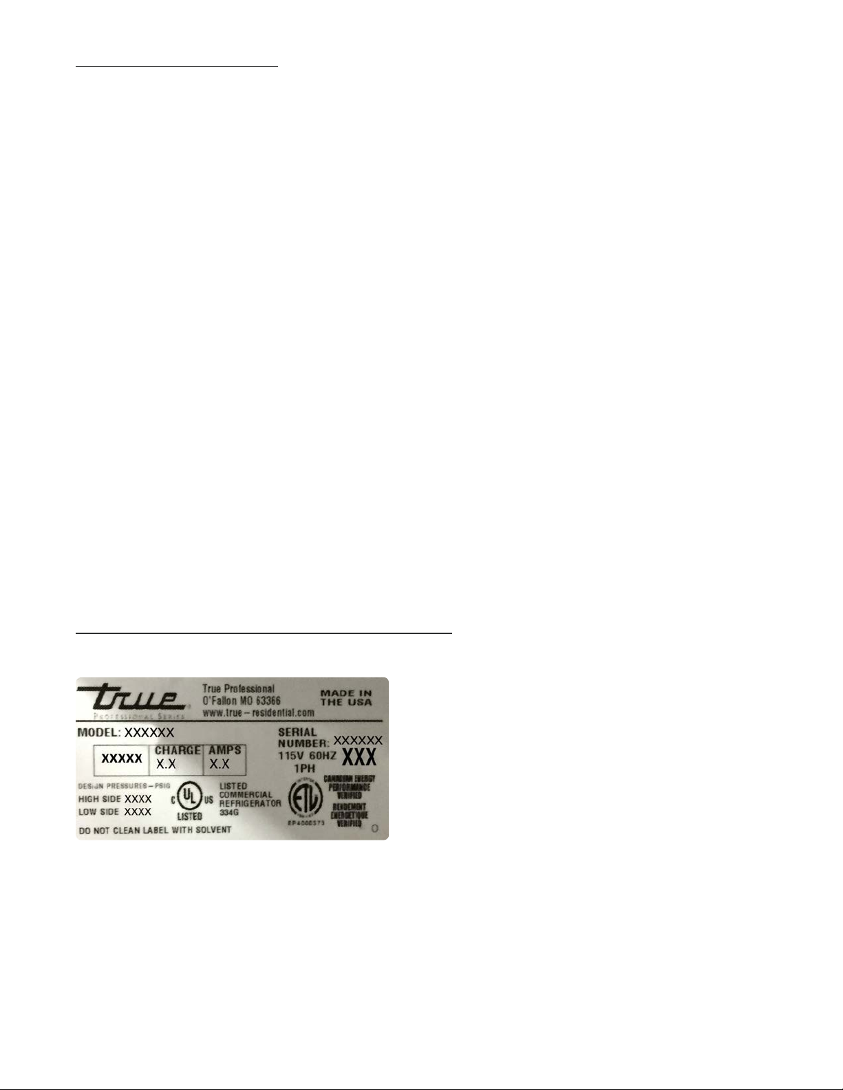
DATA TAG INFORMATION
Data tags are located on the interior upper left hand wall. The serial # is the method we track all pertinent
information for the unit.
15 & 24 INCH SERVICE MANUAL
3
Page 7

DEPARTMENT CONTACT INFORMATION
TRUE-RESIDENTIAL.COM/SUPPORT
SERVICE DEPARTMENT – SUPPORTS AND TRAINS FIELD SERVICE PROVIDERS ON TRUE RESIDENTIAL EQUIPMENT
HELPS TROUBLESHOOT AND REPAIR SERVICE ISSUES IN THE FIELD ON TRUE RESIDENTIAL PRODUCTS
Residential Phone Number : 844-746-9423
Fax : 636-980-8510
Email : TrueResidentialService@truemfg.com
Mike Hurd
Dave Swift
Hours: Monday-Thursday 7:00AM-7:00PM CST
Friday 7:00AM-6:00PM
Saturday 8:00AM-12:00PM
WARRANTY DEPARTMENT – ANSWERS QUESTIONS REGARDING WARRANTY STATUS
PROCESSES WARRANTY CLAIMS & WARRANTY PARTS ORDERS FROM SERVICE PROVIDERS
Residential Phone Number : 844-849-6179
Fax : 636-980-8510
Email: TrueResidentialWarranty@truemfg.com
Stephanie Bouxsein
Diane Javaux
Submit Claims to: TrueResidentialWarranty@truemfg.com
Hours: Monday-Thursday 7:00AM-7:00PM CST
Friday 7:00AM-6:00PM
PARTS DEPARTMENT – OFFERS NON-WARRANTY PARTS SUPPORT
Residential Phone Number : 844-849-6226
Fax : 636-272-9471
Email: TrueResidentialParts@truemfg.com
Gabriela Childers
Abby Baker
Hours: Monday-Thursday 7:00AM-7:00PM CST
Friday 7:00AM-6:00PM
FOR COMMERCIAL PRODUCT INFORMATION, PLEASE CALL 800-325-6152
TRUE RESIDENTIAL
4
®
Page 8

THANK YOU
FOR YOUR PURCHASE
Page 9
ELECTRICAL SPECIFICATIONS
Do not, under any circumstances, cut or remove the third (ground) prong from the power cord. For personal
safety, this appliance must be properly grounded.
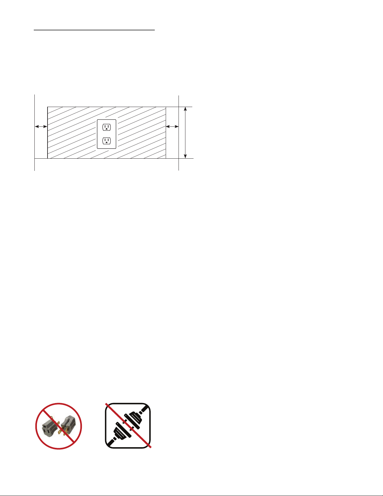
To minimize the depth of the cutout opening, the electrical outlet must be positioned as shown below. Outlet
must be flush with wall.
Rear wall of cut out
2” 2”
8”
Before your new unit is connected to a power supply, check the incoming voltage with a volt meter. If anything
less than 100% of the rated voltage for operation is noted, correct immediately.
The power cord of this appliance is equipped with a 3-prong (grounding) plug which mates with a standard
3-prong (grounding) wall outlet to minimize the possibility of electric shock hazard from this appliance. A 115V
AC, 60 Hz, 15 amp circuit breaker and electrical supply are required.
Each unit requires a dedicated circuit. Have the wall outlet and circuit checked by a qualified electrician to
make sure the outlet is properly grounded.
If the outlet is a standard 2-prong outlet, it is your personal responsibility and obligation to have it replaced with
the properly grounded 3 prong wall outlet.
Do not use an extension cord or two prong adaptor. Electrical ground is required on this appliance.
The unit should always be plugged into its own individual electrical circuit, which has a voltage rating that
matches the rating plate. This provides the best performance and also prevents overloading house wiring
circuits which could cause a fire hazard from overheated wires. Never unplug your refrigerator by pulling on
the power cord. Always grip plug firmly and pull straight out from the outlet.
Repair or replace immediately all power cords that have become frayed or otherwise damaged. Do not use
a cord that shows cracks or abrasion damage along its length or at either end. When moving the refrigerator
away from the wall, be careful not to roll over or damage the power cord.
WARNING: COMPRESSOR WARRANTIES ARE VOID IF
THE UNIT IS MORE THAN 7 FT. (2.1M) FROM PLUG-IN
CONNECTION OR IF AN EXTENSION CORD IS USED.
15 & 24 INCH SERVICE MANUAL
5
Page 10
HOME ALARM SYSTEM - DUAL ZONE WINE CABINET ONLY
Dual Zone wine units are provided with three wires located behind the kick-plate that may be connected
to a home alarm system. These connections are for low voltage, low current circuits similar to those used
as signals for alarms on doors and windows. Refer to the specifications of your alarm system to determine
the type of circuit used.
The color codes for the different circuits are as follows:
• Normally closed contacts: White with black and violet
• Normally open contacts: White with blue and black
• Common: White with black
CAUTION: ANY UNUSED TERMINALS SHOULD BE FULLY INSULATED AND ALL WIRES
SHOULD BE SECURED AWAY FROM MOVING PARTS AND SHARP EDGES.
TRUE RESIDENTIAL
6
®
Page 11
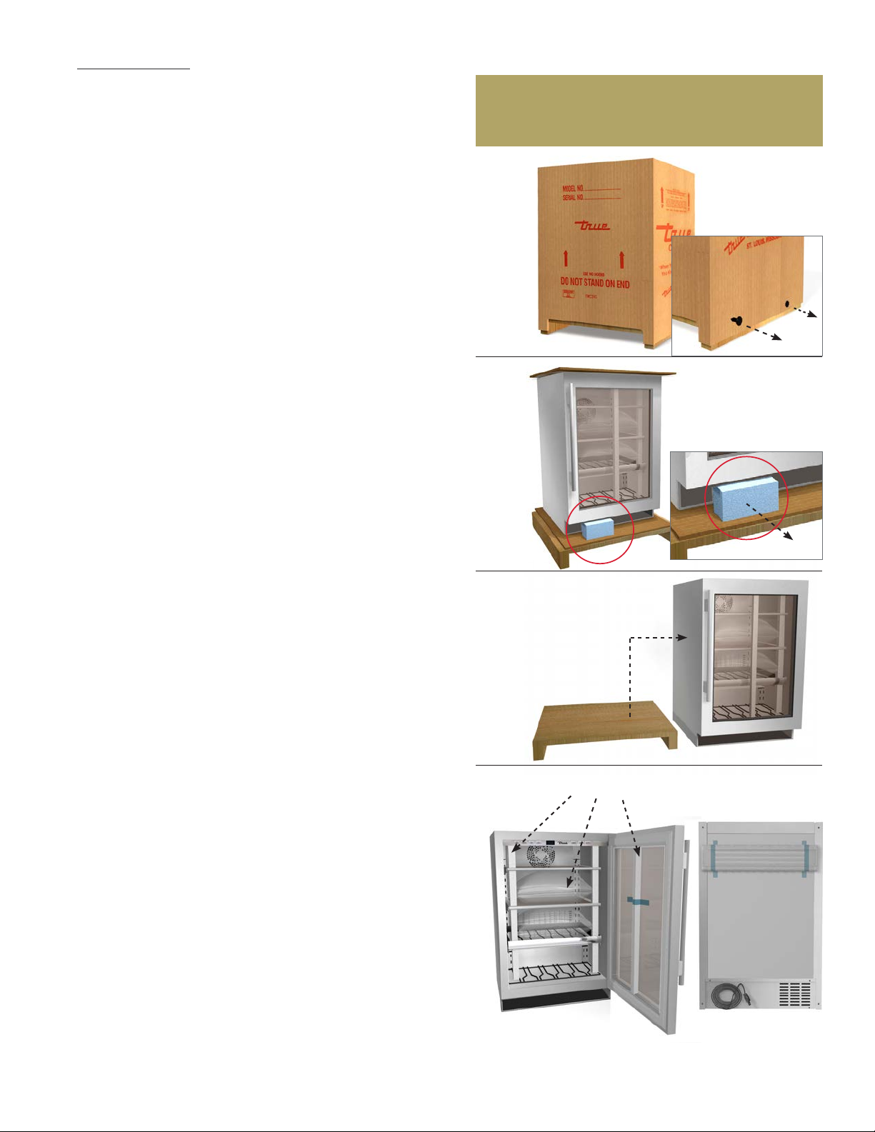
UNCRATING
Required Tools:
• Cutting utensil (utility knife)
• Claw hammer or tin snips
The following procedure is recommended for uncrating
the unit:
MOVE YOUR UNIT AS CLOSE TO THE FINAL LOCATION AS
POSSIBLE BEFORE REMOVING THE WOODEN SKID.
A. Remove nails securing cardboard box to the wooden
skid. Then discard any outer packaging (cardboard,
clear plastic).
B. IMPORTANT: Cut polyband and remove styrofoam
block from underside of the door.
INSPECT FOR CONCEALED DAMAGE.
IMMEDIATELY FILE A CLAIM WITH THE FREIGHT
CARRIER IF THERE IS DAMAGE.
A
B
C. Remove skid by carefully lifting the refrigerator off
and place skid aside.
D. Open the unit and remove any packing material.
Styrofoam, tape, and any other material used for
shipping purposes.
NOTE: KEYS FOR THE LOCK ARE PROVIDED WITH
THIS PACKET. STAINLESS STEEL UNITS
COME STANDARD WITH LOCKS. OVERLAY
PANEL READY UNITS WILL NOT BE EQUIPPED
WITH LOCKS.
NOTE: ANTI-TIP BRACKETS KIT AND DOOR STOP
ARE PACKED WITHIN THE TOE KICK WHICH
IS TAPED TO THE BACK OF THE UNIT. IF
THEY ARE NOT IN THE TOE KICK THEY WILL
BE PACKAGED INSIDE THE UNIT WITH THIS
M A NUAL.
C
D
PACKING MATERIAL
TOE KICK IS ATTACHED
TO BACK OF UNIT
FOR ANY MISSING OR BROKEN PARTS.
PLEASE CONTACT THE DEALER FROM
WHOM YOU PURCHASED THE UNIT.
15 & 24 INCH SERVICE MANUAL
7
Page 12
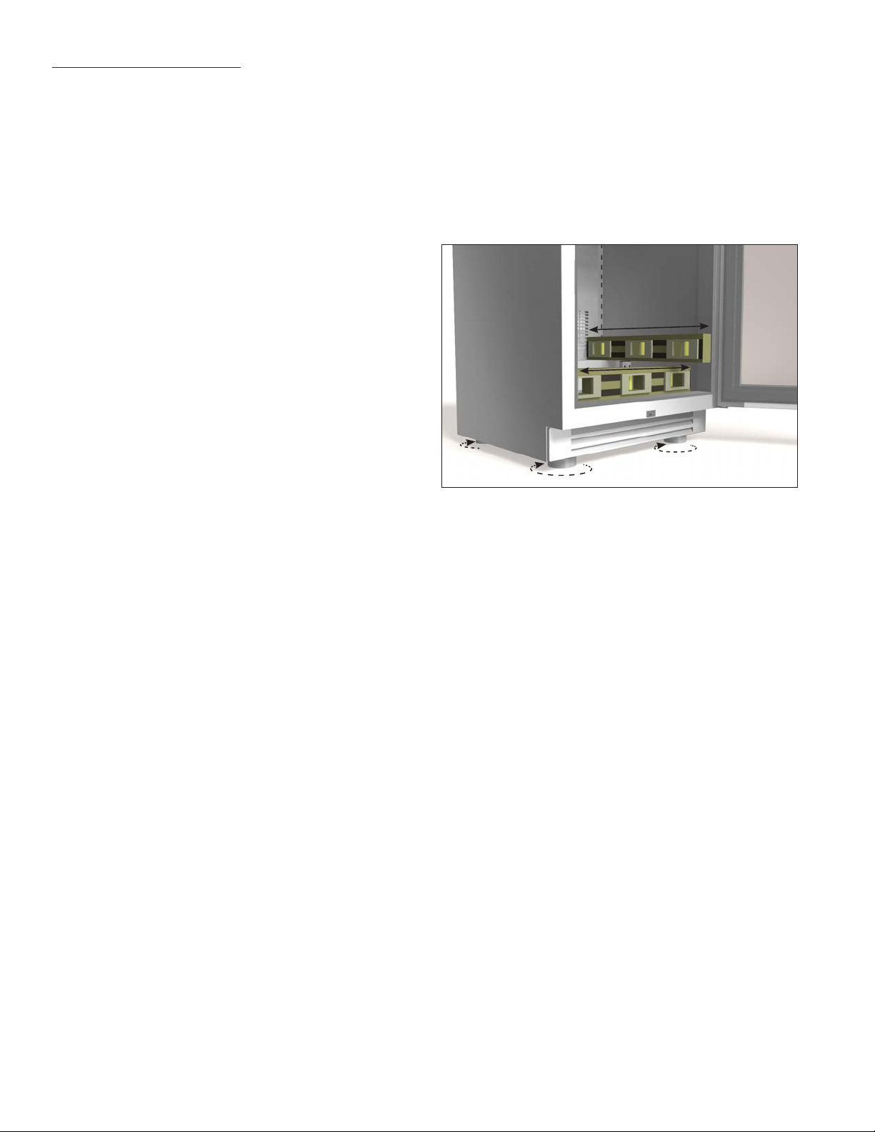
LEVELING THE UNIT
NOTE: PROPER LEVELING OF YOUR TRUE UNIT
IS CRITICAL TO OPERATING SUCCESS.
EFFECTIVE CONDENSATE REMOVAL AND
DOOR OPERATION WILL BE EFFECTED BY
LEVELING.
STEP 1 - Move the unit near the final location.
STEP 2 - Level your unit from the interior floor front
to back and side to side with a level. If the
refrigerator is not level adjust the stainless
steel leg levelers. The leg levelers can be
adjusted by turning CCW to reach the desired
leveling height as shown in the illustration
below.
STEP 3 - Free plug and cord from back of unit.
STEP 4 - The unit should be placed close enough to
the electrical supply so that extension cords
are never used. Plug unit directly into the
wall outlet.
STEP 5 - Once installed in final location, re verify level
and make final adjustments to the front legs.
STEP 6 - Insert the toe kick on the clips (A) Version or
magnets (B) version.
TRUE RESIDENTIAL
8
®
Page 13
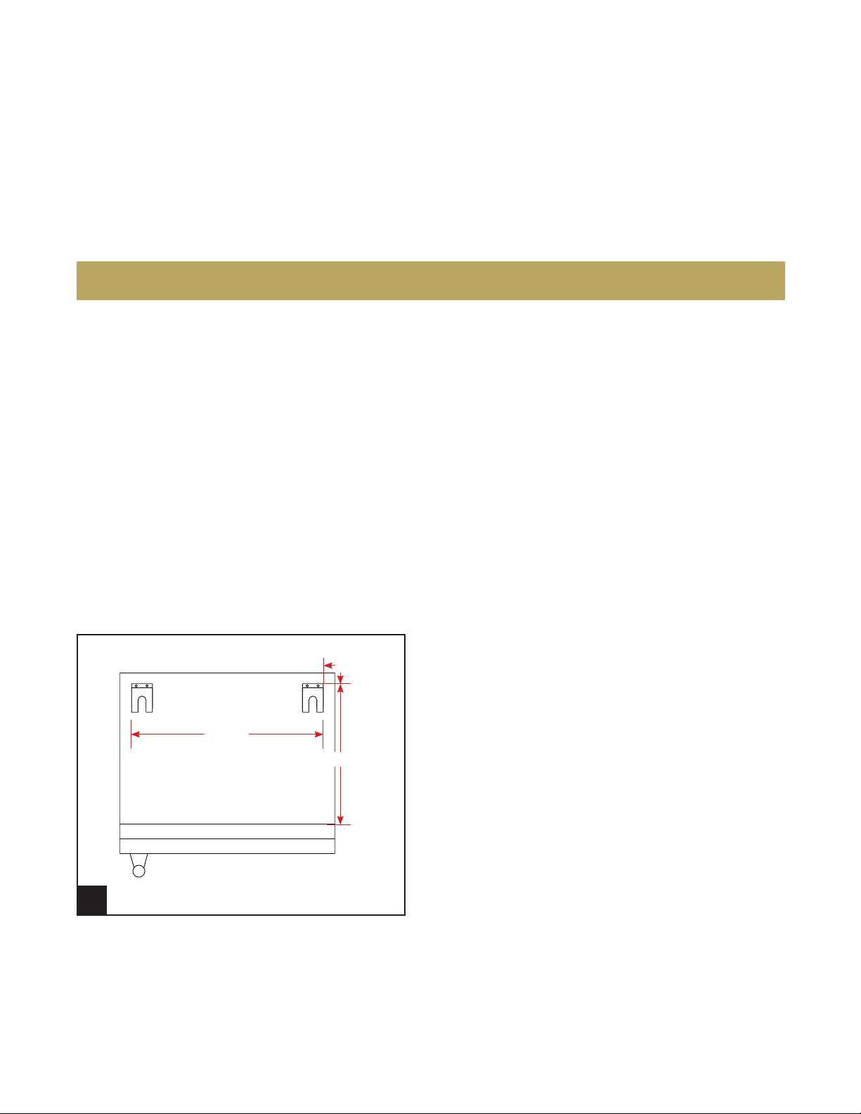
ANTI-TIP BRACKET INSTALLATION
3.23.17 AC
TRUE RESIDENTIAL
®
211354
PRODUCT ADVISEMENT
KIT INCLUDES
• 2 Anti-tip brackets
• 4 Concrete screws (blue)
• 4 Wood screws (brass)
TOOLS REQUIRED
• Power drill
• Measuring Tape
IMPORTANT!
ALL FREE STANDING DRAWER (TUR-24D) OR STACKED UNITS MUST HAVE ANTI-TIP BRACKETS INSTALLED.
TIP-OVER HAZARD: A CHILD OR ADULT CAN TIP THE REFRIGERATOR. FAILURE TO FOLLOW THESE INSTRUCTIONS CAN RESULT
IN PROPERTY OR BODILY HARM.
BEFORE MOVING UNIT TAKE PRECAUTIONS TO PROTECT THE FLOOR.
Read all installation instructions first. Install the anti-tip brackets to hold both rear legs of the unit. Follow these steps
to secure the brackets to the floor before moving the unit into final operating position.
Contact a qualified floor installer for the best procedure of drilling mounting holes through your type of floor.
STEP 1
Back
3/16 "
22
Front
ANTI-TIP BRACKET (TOP VIEW)
1
18
27/ 32"
1/2"
Determine the location of the unit. The anti-tip
brackets will be installed 27/32" inset from the back
and sides of the unit. You can also measure 18 1/2"
from the front of the unit (not including the lower
louver grill). Using the bracket as a template, mark
the holes for drilling.
15 & 24 INCH SERVICE MANUAL
9
Page 14
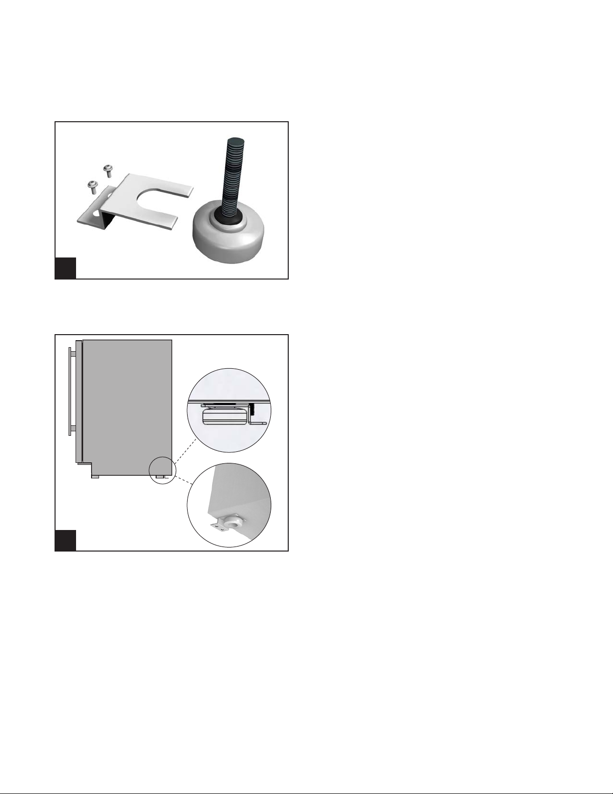
ANTI-TIP BRACKET INSTALLATION
3.23.17 AC
TRUE RESIDENTIAL
®
211354
PRODUCT ADVISEMENT
2
STEP 2
To mount the anti-tip bracket to wood floor, drill pilot
holes for each of the bracket holes. To mount the
anti-tip bracket to concrete or ceramic floor use a
masonry bit to drill pilot holes. Align anti-tip bracket
holes with the holes in the floor. Fasten anti-tip
bracket with screws provided using the brass colored
screw for wood, or blue colored masonry screw for
concrete.
STEP 3
Move unit into final position making sure rear leveling
legs slide into the anti-tip brackets.
3
TRUE RESIDENTIAL
10
®
Page 15
DOOR STOP INSTALLATION
INSTRUCTIONS FOR STAINLESS STEEL MODELS
ALL UNITS ARE PROVIDED WITH AN OPTIONAL DOOR STOP. WHEN INSTALLED, THE DOOR STOP WILL PREVENT
DAMAGE TO SURROUNDING CABINETS BY RESTRICTING THE DOOR FROM OPENING PAST APPROXIMATELY 120º
WITH A STANDARD HINGE OR 90º WITH AN 90º HINGE (OPTIONAL).
Hinge
Door stop
STEP 1
To install the door stop, use the 2 screws provided
and secure the bracket to the bottom of the door on
the same side as the hinge.
(OPTIONAL) 90° HINGE INSTALLATION
INSTRUCTIONS FOR STAINLESS STEEL MODELS
KIT INCLUDES
• 90º Hinge (left or right)
• Door stop bracket (left or right)
TOOLS REQUIRED
• 3/8" Socket wrench
• Phillips screwdriver
Door stop
installed
1
STEP 1
Remove toe kick.
15 & 24 INCH SERVICE MANUAL
11
Page 16
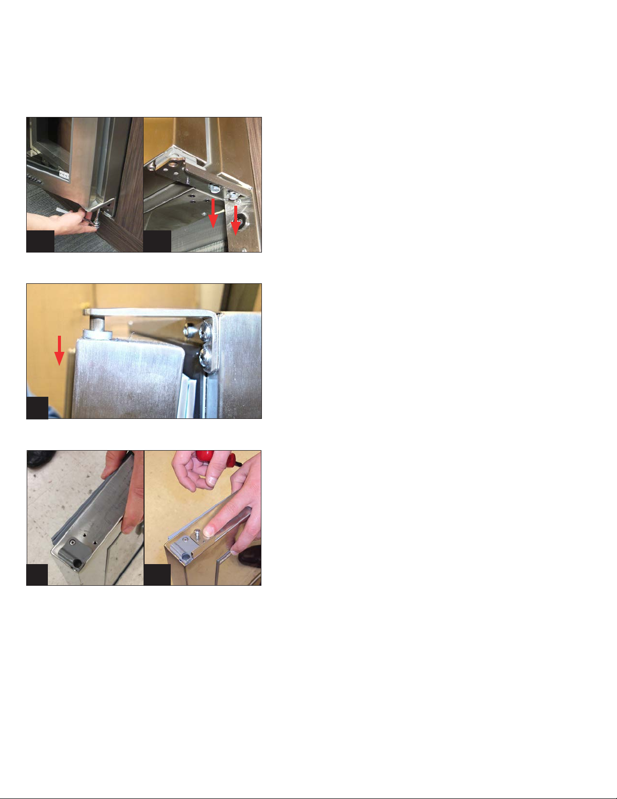
(OPTIONAL) 90° HINGE INSTALLATION
INSTRUCTIONS FOR STAINLESS STEEL MODELS
STEP 2
WARNING: Support the door while removing hinge.
Door is heavy and weight will cause it to drop if not
supported.
Remove 2 3/8" bolts to detach 120º door hinge
(standard).
2a
3
2b
STEP 3
Slowly remove door from unit by sliding down from
top hinge.
STEP 4
Install door stop using screws already installed.
Reinstall door by sliding up into top hinge.
4a
TRUE RESIDENTIAL
12
4b
®
Page 17
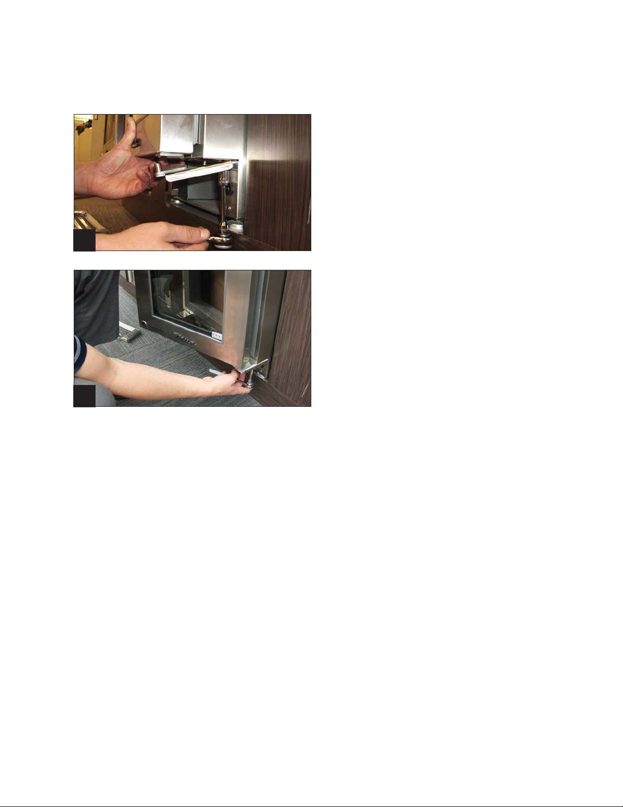
(OPTIONAL) 90° HINGE INSTALLATION
INSTRUCTIONS FOR STAINLESS STEEL MODELS
STEP 5
Install 90º hinge with the 2 3/8" bolts that you
removed. Note: Do not tighten screws all the way
until door adjustments have been made.
5
STEP 6
Align door with lock latch and light switch.
Tighten screws.
6
15 & 24 INCH SERVICE MANUAL
13
Page 18
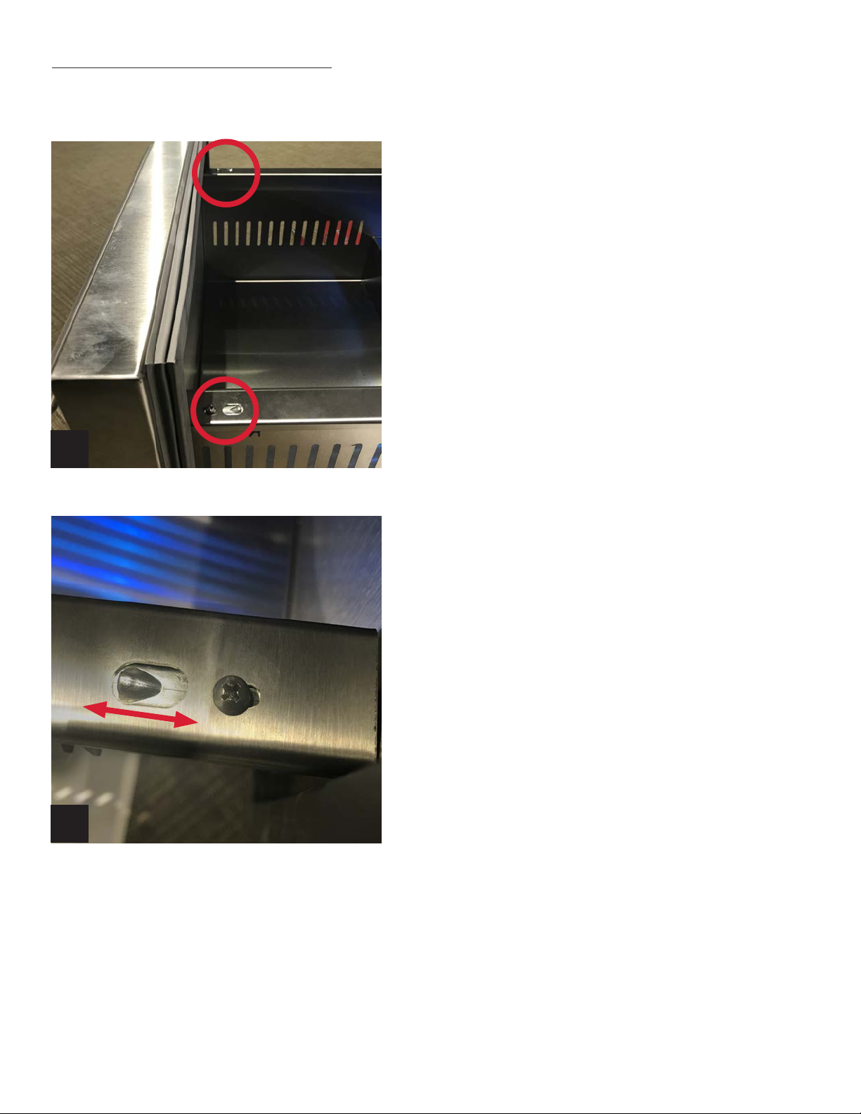
DRAWER DEPTH ADJUSTMENT
1
STEP 1
Loosen the left and right screws that mount the drawer
frame to the slide. See Image 1.
2
STEP 2
To bring the drawer out to the front of the unit, pull the
drawer out where the tab is seated towards the rear of the
unit. See Image 2.
STEP 3
Hold drawer position and tighten screws.
TRUE RESIDENTIAL
14
®
Page 19

DRAWER FRONTS ON TRUE DRAWER REFRIGERATORS ADJUSTMENT
STEP 1 - Open the drawer that needs adjustment.
STEP 2 - Locate the two Phillips screws on each side of the drawer frame.
See figure 1
STEP 3 - Loosen the 2 screws on each side to get left to right movement
on the drawer front.
STEP 4 - Hold adjustment in place and re tighten the screws back down.
FIGURE 1.
DRAWER GLIDES ON TRUE DRAWER REFRIGERATORS ADJUSTMENT
STEP 1 - Remove screws (one on each side) on top of drawers at front.
STEP 2 - Remove drawers (lift out from the front)
STEP 3 - Loosen the two screws on the glide
STEP 4 - Use bottom screw to adjust glide
STEP 5 - Tighten side screws
STEP 6 - Replace drawer by aligning into tabs (in back)
STEP 7 - Reinsert screws in front
1
3
6
2
4
5
7
15 & 24 INCH SERVICE MANUAL
15
Page 20
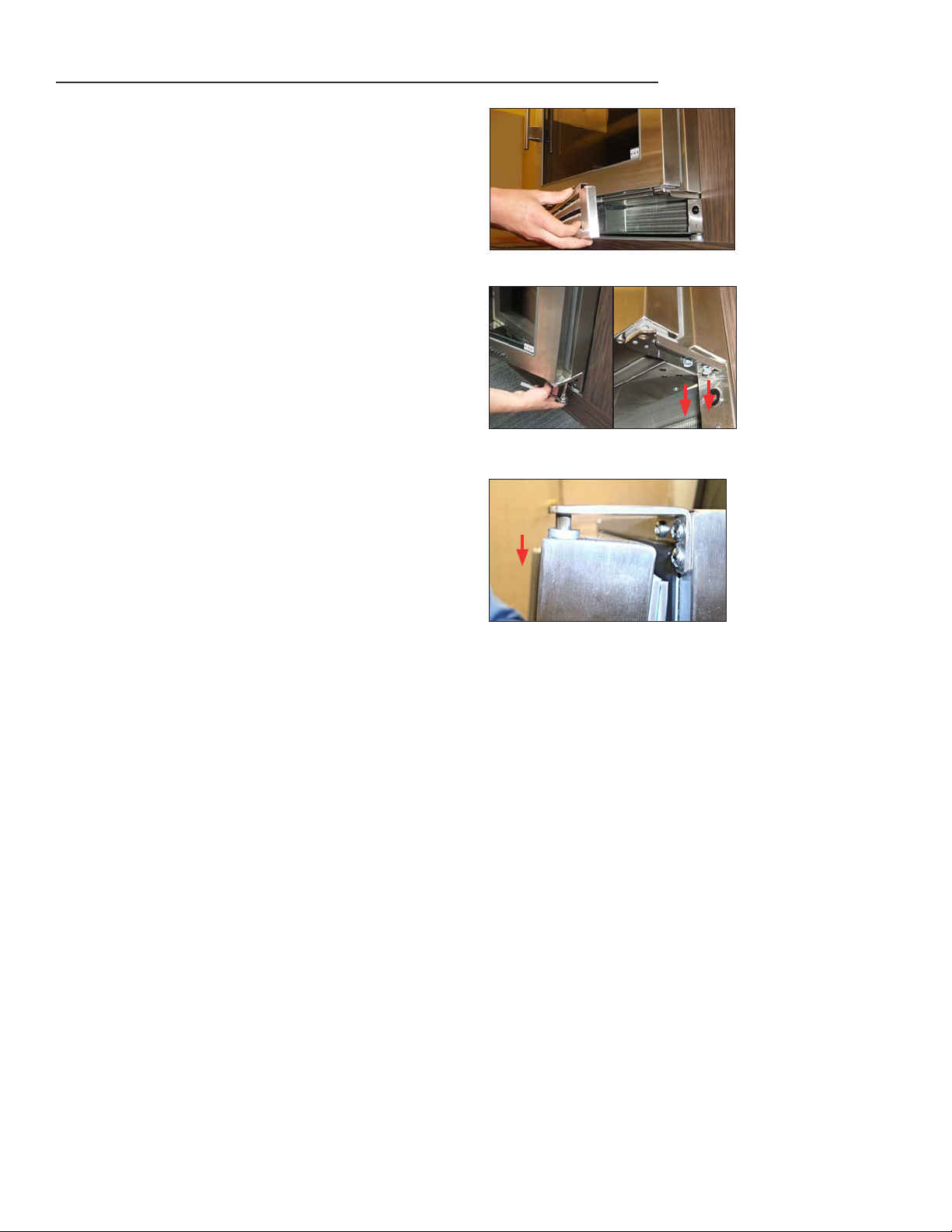
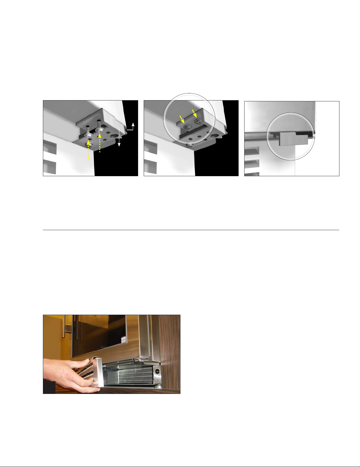
DOOR REMOVAL
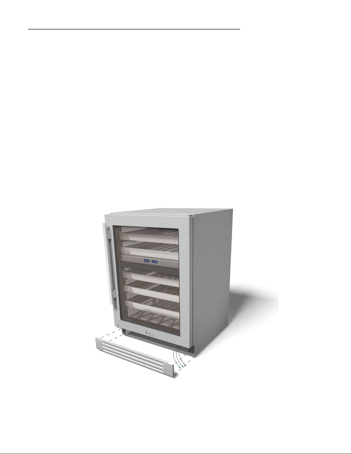
STEP 1 - Remove the louver grill from the bottom of
the unit by simply pulling the grill toward the
front of the unit. See image 1.
STEP 2 - Support the door with your knee or a block to
prevent the door from falling to the ground
when the bolts are removed.
STEP 3 - Remove the two 3/8-inch bolts from the
bottom hinge using a ratchet and socket. See
image 2A and 2B.
STEP 4 - Pull the hinge out of the bottom of the door
and set it aside.
1
STEP 5 - Once these two bolts are removed, slightly
open the door, still supporting the weight
with your knee or a block, slowly allow the
door to drop down off the top hinge pin. See
image 3.
STEP 6 - Reinstall door by reversing sequence.
2A
3
2B
TRUE RESIDENTIAL
16
®
Page 21

STAINLESS STEEL & STAINLESS GLASS DOOR ADJUSTMENTS
ALL VERSIONS
PLEASE NOTE: DOOR HINGING ON TRUE PRODUCTS ARE NOT INTERCHANGEABLE. IT IS NEVER RECOMMEND TO
ATTEMPT MOVING DOOR HINGING TO THE OPPOSITE SIDE THE UNIT WAS BUILT WITH. THIS MAY CAUSE SERIOUS
DAMAGE AND HARM.
STEP 1 - Make sure the unit is completely level and
in place.
STEP 2 - Remove the bottom louver grill from the
unit. See image 1.
NOTE: A version grills are clipped in and B
version grills are held on with magnets.
1
STEP 3 - With the door shut loosen the two 3/8-inch
bolts. See image 2.
STEP 4 - While supporting the door, open slightly
and shift the door up or down on the
handle side. See image 3.
STEP 5 - Hold the adjusted door and retighten
the two 3/8 inch bolts until very snug to
prevent the adjustment from coming loose.
STEP 6 - Test the door by opening and closing,
making sure the door is not hitting the lock
latch (image 4a) and ensure that the door
makes contact with the door switch (image
4b).
STEP 7 - Re-install the louver grill.
2
3
4A 4B
15 & 24 INCH SERVICE MANUAL
17
Page 22

OVERLAY PANEL & OVERLAY PANEL GLASS DOOR ADJUSTMENTS
PLEASE NOTE: DOOR HINGING ON TRUE PRODUCTS ARE NOT INTERCHANGEABLE. IT IS NEVER RECOMMEND TO
ATTEMPT MOVING DOOR HINGING TO THE OPPOSITE SIDE THE UNIT WAS BUILT WITH. THIS MAY CAUSE SERIOUS
DAMAGE AND HARM.
DOOR ADJUSTMENT UP AND DOWN - ALL VERSIONS
STEP 1 - Make sure the unit is completely level and
in place.
STEP 2 - Remove the bottom louver grill from the
unit. See image 1.
NOTE: A version grills are clipped in and B
version grills are held on with magnets.
1
STEP 3 -
STEP 4 - While supporting the door, open slightly
STEP 5 - Hold the adjusted door and retighten
DOOR ADJUSTMENT LEFT TO RIGHT
STEP 1 - Loosen the top and bottom Phillips screws
STEP 2 - Shift the entire door left or right to align to
With the door shut loosen the two 3/8-inch
bolts. See image 2 and 3.
and shift the door up or down on the
handle side. See image 4.
the two 3/8 inch bolts until very snug to
prevent the adjustment from coming loose.
(do not remove screws unless you want to
remove the door). See image 5 and 6.
desired position. See image 7.
2
3
4
STEP 3 - While holding the door in position re-tighten
the upper and bottom screws to hold new
adjustment.
STEP 4 - To adjust the upper only, loosen the two
screws on the upper hinge bracket and shift
door accordingly. See image 5.
STEP 5 - To adjust the bottom only, loosen the two
screws on the bottom hinge bracket and
shift door accordingly. See image 6.
TRUE RESIDENTIAL
18
®
65
7
Page 23

WINE SHELVING ADJUSTMENT
The glide out wine shelves in TBC, TWC and TWZ-DZ
models consist of 3 pieces. These pieces are the wire
wine rack and 2 mounting bracket/glide assemblies
(one for the hinge side and one for the non-hinge side).
To remove the wine shelf, pull up on the front of the
wine rack and it will separate from the two mounting
brackets. The two mounting brackets may now be
removed from the pilasters by lifting straight up then
pulling the brackets out of the pilasters.
NOTE: WHEN REINSTALLING THE BRACKETS,
THE BRACKET WITH THE LARGER VIBRATION
BUMPER MUST BE INSTALLED ON THE SAME
SIDE OF THE CABINET AS THE DOOR HINGE.
WHEN REINSTALLING THE WINE RACK, BE
SURE THAT THE BACK OF THE RACK HOOKS
UNDERNEATH THE TAB ON THE GLIDE.
The tab on the front of the glide must also fit securely
in the gap between the handle and the rack (see
illustration). If the fit is too tight, you may need to
loosen the screws on the back of the handle to increase
the gap.
The wine shelves are held securely by the anti-vibration
bumpers. If there is too much play side-to-side, tighten
the bumpers against the compartment walls by rotating
with your fingers.
GLASS SHELVING ADJUSTMENT
The glide out glass shelves are already attached
to the mounting bracket/glide assemblies.
To install the glass shelves insert mounting
brackets into pilasters.
To remove the glass shelves, simply lift straight
up then pull the brackets out of the pilasters.
ANTI-VIBRATION
BUMPERS
15 & 24 INCH SERVICE MANUAL
19
Page 24

4.10.17 AC
TRUE RESIDENTIAL
®
981897
PRODUCT ADVISEMENT
STACKING KIT INSTRUCTIONS
TOOLS REQUIRED
• 5/16-inch socket and ratchet
• Level
• Floor proctor
• Extra person(s)
KIT INCLUDES
• (1) Louver grill. Note: A version models will use
clips to mount the grill. B version models will
have magnets.
• (2) stacking brackets
• (4) 5/16 inch screws
• Anti-tip bracket kit
STACKING
BRACKETS
1
• Uncrate and secure doors, shelving, and drawers to prevent damage when handling the units.
• Install the anti-tip bracket per instructions (see separate).
• Verify the anti-tip brackets are properly located by trial fitting the lower unit in place. If so pull the unit back out
to prepare Step 1.
PROTECT THE FLOOR, SURROUNDING CABINETRY AND THE UNITS AT ALL TIMES.
THIS PROCEDURE REQUIRES ASSISTANCE FROM EXTRA PERSON(S).
STEP 1
Carefully lift the top cabinet and place on the lower
cabinet making sure the upper unit is flush with the
lower unit’s sides and back.
STEP 2
Install the rear stacking brackets using the provided
5/16-inch screws. NOTE: DO NOT TIGHTEN THE
BRACKETS ALL THE WAY UNTIL LATER STEPS.
See Image 1.
LED LIGHTING
• The lighting in all True Residential
• Each compartment has 1 or 2 LED modules that are powered by a driver.
• The modules have an IC chip in them to change their color. A short power interruption is the trigger to
change the color.
• If the colors are ever out of sync, they can be reset by changing the color 10 times in a row. This will reset
all modules back to white.
• The LED modules run off a 10V DC power supply which is located next to the microprocessor control. The
WHEN LIGHTS ARE SET TO GO OFF WHEN THE DOOR IS SHUT, 30 SECONDS LATER THE LED’S WILL HAVE A SPLIT
SECOND FLASH. THIS IS BY DESIGN TO ALLOW THE LED’S TO RELEASE STORED ELECTRICITY. IT WILL DO THIS
ONLY ONE TIME, EACH TIME THE DOOR IS SHUT.
IF THE LIGHTS ARE SET TO STAY ON EVEN WHEN THE DOOR IS SHUT, THIS WILL NOT OCCUR.
power supply has 115V AC incoming, then 10V DC outgoing.
®
Undercounter Models is an LED module system.
RED AND BLUE
10V DC
BLACK AND WHITE
120V AC
TRUE RESIDENTIAL
20
®
Page 25

4.10.17 AC
TRUE RESIDENTIAL
®
981897
STACKING KIT INSTRUCTIONS
PRODUCT ADVISEMENT
KIT INCLUDES
• (1) Louver grill. Note: A version models will use
clips to mount the grill. B version models will
have magnets.
• (2) stacking brackets
TOOLS REQUIRED
• 5/16-inch socket and ratchet
• Level
• Floor proctor
• Extra person(s)
• (4) 5/16 inch screws
• Anti-tip bracket kit
PROTECT THE FLOOR, SURROUNDING CABINETRY AND THE UNITS AT ALL TIMES.
• Uncrate and secure doors, shelving, and drawers to prevent damage when handling the units.
• Install the anti-tip bracket per instructions (see separate).
• Verify the anti-tip brackets are properly located by trial fitting the lower unit in place. If so pull the unit back out
to prepare Step 1.
THIS PROCEDURE REQUIRES ASSISTANCE FROM EXTRA PERSON(S).
STEP 1
Carefully lift the top cabinet and place on the lower
STACKING
BRACKETS
cabinet making sure the upper unit is flush with the
lower unit’s sides and back.
STEP 2
Install the rear stacking brackets using the provided
5/16-inch screws. NOTE: DO NOT TIGHTEN THE
BRACKETS ALL THE WAY UNTIL LATER STEPS.
See Image 1.
1
15 & 24 INCH SERVICE MANUAL
21
Page 26

4.10.17 AC
TRUE RESIDENTIAL
®
981897
PRODUCT ADVISEMENT
STACKING KIT INSTRUCTIONS
STEP 3
Level the upper and lower unit front to back and left
to right by placing a small level on the interior floor.
See Image 2.
STEP 4
Now tighten all (4) 5/16-inch screws to secure the
brackets to the units.
STEP 5
Carefully put the stacked units in their final setting.
Make sure the bottom unit’s rear legs are securely
locked into the anti-tip brackets.
STEP 6
Install supplied louver grill on upper unit. See Image 3.
2
3
24 INCH
TRUE RESIDENTIAL
22
®
Page 27

TECHNICAL DATA
s o f t w a r e I n f o r m a t I o n a n D st a r t u P m o D e
s e q u e n C e o f o P e r a t I o n
u s e r I n t e r f a C e C o m m a n D s
23 - 44
D e f r o s t
e v a P o r a t o r C o v e r r e m o v a l
e v a P o r a t o r s e C t I o n l a y o u t
P r o B e v a l u e s
e v a P o r a t o r f a n D r I v e r
C o n t r o l B o a r D r e P l a C e m e n t & m o D e l s e l e C t s e q u e n C e o f o P e r a t I o n
w I r I n g D I a g r a m s
15 & 24 INCH SERVICE MANUAL
23
Page 28

SOFTWARE INFORMATION AND START UP MODE
All software codes will be displayed every time the machine is powered up (power must be disconnected)
– the software code will be displayed for a minimum of 25 seconds. (Does not apply to ice machine or
uprights)
1) Software Version: 66 (does not apply to ice machine or uprights)
• Only used for A version models (Model number will finish with the letter “A”)
Example:
º
F
º
C
ICE
2) Software Code: 73 (does not apply to ice machine or uprights)
• Only used for B version models (Model number will finish with the letter “B”)
• This software code was replaced by software version: 94
• If a control board has software code “73” and fails, will be replaced with new software version “94”
MODEL
SIZE
HINGE
DOOR
EDITION
TWC - 24DZ - L - SG - A
TRUE WINE
CABINET
24”
DUAL ZONE
HINGED ON LEFT
HANDLE ON RIGHT
STA INLESS
GLASS
Example:
º
F
º
C
ICE
MODEL
SIZE
HINGE
DOOR
EDITION
TWC - 24DZ - L - SG - B
TRUE WINE
CABINET
24”
DUAL ZONE
HINGED ON LEFT
HANDLE ON RIGHT
STA INLESS
GLASS
SECOND
REVISION
3) Software Code: 94 (does not apply to ice machine or uprights)
• Currently used on B version models (Model number will finish with the letter “B”)
• Software version “94” has a hard-reset option. A hard reset will eliminate the need to disconnect
power to the unit to verify software and program the model when needed.
Example:
º
F
º
C
ICE
MODEL
SIZE
HINGE
DOOR
EDITION
TWC - 24DZ - L - SG - B
TRUE WINE
CABINET
24”
DUAL ZONE
HINGED ON LEFT
HANDLE ON RIGHT
STA INLESS
GLASS
SECOND
REVISION
HARD-RESET PROCEDURE
In order to perform a hard-reset of the machine please follow these steps:
i. Turn the unit Off using the power button (hold for 3 seconds)
ii. Press and hold the +
iii. A successful hard-rest will show a 3-digit code for 25 seconds followed by “94” for 20 seconds. After
a total of 45 seconds, compartment temperature will be displayed.
HARD-RESET FEATURE MAY NOT FUNCTION FOR ALL B VERSION UNITS. IF THE
DISPLAY CONTINUES TO SHOW “OFF” AFTER PERFORMING A HARD-RESET.
TRUE RESIDENTIAL
24
®
Page 29

SEQUENCE OF OPERATION
The operating system consist of these components.
ELECTRONIC CONTROL BOARD – Main control of the entire unit’s functionality. The control board is located in the
interior ceiling for all models except (TUF & DZ) TUF board location is behind the rear back cover. DZ boards are
located in the interior ceiling of the center mullion.
COMPRESSOR – Variable speed and single speed compressors depending on version. Please see page 47
CONDENSER FAN MOTOR – Located behind the rear panel of the unit. The condenser fan should always run while the
compressor is running.
24" units - 120VAC condenser fan motor
15" units - 10VDC condenser fan motor
EVAPORATOR FAN MOTOR – Located behind the interior back cover. The evaporator fan motor will cycle off with the
refrigeration cycle on refrigerators. On wine units the evaporator fan will run all the time. The fan will always shut off
when the door is opened.
ONE COMPARTMENT PROBE (Labeled with two blue stripes on "A"versions) (solid blue on "B"versions) – this sensor
controls the cut in and cut out of the refrigeration system.
ONE EVAPORATOR PROBE (Labeled with 1 blue stripe on "A"versions) ( solid blue on "B"versions) – this sensor
controls the defrost function. (Described in detail in the "Defrost" section of this manual)
When power is supplied, the LCD will show a software version code for a minimum of 25 seconds. This is for
manufacturing process only.
From the “off” to the "on" position using the interface power button, the following will happen:
1. Interior LED lights will illuminate.
2. Display readout will show interior cabinet temp based off the compartment probe.
3. After a 2-minute delay the refrigeration system will start.
The refrigeration system (compressor, condenser fan motor, evaporator fan motor) will run until cut out temperature is
reached.
PLEASE NOTE: THE CUT OUT TEMPERATURE IS BASED ON THE COMPARTMENT PROBE, NOT THE DISPLAY
TEMPERATURE. OUR DISPLAY TEMPERATURE IS A CALCULATION AND IS NOT REFLECTING REAL TIME TEMP.
Once the cut out temperature is reached the we will shut the refrigeration system off.
The cycle will repeat when the compartment probe tells the control board to cut back in.
NOTE: THE CONTROL HAS A PRESET 7 MINUTE ANTI SHORT CYCLE.
DUAL ZONE
The TWC-24DZ has two zones which can be independently set for different temperatures.
Each zone has its own display, evaporator coil, evaporator fan and probes.
The zones share the compressor, condenser coil, and condenser fan motor.
Refrigerant is directed to either zone through a bi-stable solenoid valve.
Only one zone can be cooled at a time.
The control continually checks to see which zone is demanding for cooling. If both zones need cooling, the control will
switch from cooling one zone to the other every 20 minutes.
NOTE: THE UPPER ZONE HAS PRIORITY WHEN THE CABINET IS FIRST POWERED ON AND WILL ONLY START TO
COOL THE LOWER AFTER THE UPPER ZONE SET POINT HAS BEEN MET (ONLY ON START UP)
15 & 24 INCH SERVICE MANUAL
25
Page 30

USER INTERFACE COMMANDS ON TRUE PRECISION CONTROL
08 .10.17 SB
TRUE RESIDENTIAL
®
206582
CONTROL COMMANDS
KE Y
COMBINATIONS
LCD READOUTS DESCRIPTION
“B” Revision ContRol BoARd 73
tWC-24/tBC-24/tUR-24/tUR-24d
08 .10.17 SB
TRUE RESIDENTIAL
®
206582
CONTROL COMMANDS
KE Y
COMBINATIONS
LCD READOUTS DESCRIPTION
Software Version
73ºC
º
F
ICE
º
C
Code is displayed for 45 seconds when power is
supplied to the unit.
Off / On
º
F
ICE
º
C
Power unit off / on.
Set Point
º
F
ICE
º
C
Press to display set point.
Decrease Set Point
º
F
ICE
º
C
Press to decrease set point.
Minimum set points:
33ºF - Refrigerators
40ºF - Wine units
Increase Set Point
º
F
ICE
º
C
Press to increase set point.
Maximum set points:
47ºF - Refrigerators
65ºF - Wine units
Accent Light
º
F
ICE
º
C
Turn accent light on/off. When icon is displayed, light
remains on at all times.
Color
Switch LED colors - Slowly press and release to
switch between 14 colors.
Alarm
º
F
ICE
º
C
Set high temperature and door ajar alarm.
Door ajar - 7 minutes.
High Temps (1 consecutive hour):
50°F - Refrigerator
70°F - Wine Cabinet
+
Temperature Scale
º
F
ICE
º
C
Toggle between °C / °F.
“B” Revision ContRol BoARd 73
tWC-24/tBC-24/tUR-24/tUR-24d
08 .10.17 SB
TRUE RESIDENTIAL
®
206582
CONTROL COMMANDS
+
Lock
º
F
ICE
º
C
Lock / Unlock Keypad.
+
Sabbath Mode
º
F
ICE
º
C
Sets Sabbath mode – Star K certified. Kosher
compliant.
+
Showroom Mode
º
F
ICE
º
C
Displays set point.
Lights are fully functional.
Deactivates refrigeration system.
Disables power off function.
KE Y
COMBINATIONS
LCD READOUTS DESCRIPTION
“B” Revision ContRol BoARd 94
tWC-24/tBC-24/tUR-24/tUR-24d
®
On/Off (hold 3 seconds)
TRUE RESIDENTIAL
26
®
Press and release to show set point for 5 seconds.
After 5 seconds the display will resort back to
average box temp.
NOTE: 15 inch units use "up" or "down" button
Press to decrease set point.
Minimum set points:
33˚F - Refrigerators
40˚F - Wine Units
-4˚ F - Freezer
Press to increase set point.
Maximum set points:
47˚F - Refrigerators
65˚F - Wine Units
-4˚ F - Freezer
Press and release the button combination to start the color cycle.
Press and release the button combination again to choose the
desired color.
NOTE: Dual Zone models will use "mode + light"
NOTE: 15 inch models will use "light + up arrow"
NOTE: "A" version has 3 colors.
Activates / deactivates alarm
NOTE: 15 inch units use "POWER + DOWN"
24 inch models only
NOTE: 15 inch units use "light" button
Display set point.
Lights are fully functional.
Deactivates refrigeration system.
Disables power off function.
NOTE: 15 inch units use "light" button
Page 31

08 .10.17 SB
TRUE RESIDENTIAL
®
206582
CONTROL COMMANDS
+
Lock
º
F
ICE
º
C
Lock / Unlock Keypad.
+
Sabbath Mode
º
F
ICE
º
C
Sets Sabbath mode – Star K certified. Kosher
compliant.
+
Showroom Mode
º
F
ICE
º
C
Displays set point.
Lights are fully functional.
Deactivates refrigeration system.
Disables power off function.
+
Hard Reset (hold 3 sec)
To initiate hard reset, unit must be in the “off”
position. This feature is used to reset the control.
Refrigeration Error
º
F
ICE
º
C
Unit has not reached desired set point after 15 hours
of run down. Service recommended. Power unit off
and back on to reset.
Compartment Probe
Failure Only
º
F
ICE
º
C
Compartment probe has failed.
Evaporator Probe Failure
Only
º
F
ICE
º
C
Evaporator probe has failed.
Both Probe Failure
º
F
ICE
º
C
Compartment and evaporator probes have failed.
Change both and reset power to the control board to
clear the error message. Unit will run 3 min. on and 3
min. off until probes are changed.
High Temperature Alarm
Set high temperature alarm.
High Temps (1 consecutive hour):
50°F - Refrigerator
70°F - Wine Cabinet
Door Ajar Alarm Door is ajar (7 minutes)
KE Y
COMBINATIONS
LCD READOUTS DESCRIPTION
“B” Revision ContRol BoARd 94
tWC-24/tBC-24/tUR-24/tUR-24d
º
F
ICE
º
C
º
F
ICE
º
C
º
F
ICE
º
C
USER INTERFACE COMMANDS ON TRUE PRECISION CONTROL
08 .10.17 SB
TRUE RESIDENTIAL
®
206582
CONTROL COMMANDS
KE Y
COMBINATIONS
LCD READOUTS DESCRIPTION
“B” Revision ContRol BoARd 73
tWC-24/tBC-24/tUR-24/tUR-24d
CONTROL COMMANDS
04 .10.17 AC
TRUE RESIDENTIAL
®
206582
Compartment Probe
Failure (Zone 2)
º
F
ICE
º
C
Compartment probe has failed in Zone 2.
Evaporator Probe Failure
(Zone 2)
º
F
ICE
º
C
Evaporator probe has failed in Zone 2.
Both Probe Failure
(Zone 2)
º
F
ICE
º
C
Compartment and evaporator probes have failed in
Zone 2. Change both and reset power to the control
board to clear the error message.
KE Y
COMBINATIONS
LCD READOUTS DESCRIPTION
“B” Revision ContRol BoARd 94
tWC-24dZ
08 .10.17 SB
TRUE RESIDENTIAL
®
206582
CONTROL COMMANDS
KE Y
COMBINATIONS
LCD READOUTS DESCRIPTION
Software Version
94ºC
º
F
ICE
º
C
Code is displayed when power is supplied to the unit or a
hard-reset is done.
Off / On (hold 3 sec)
º
F
ICE
º
C
Power unit off / on.
Set Point
º
F
ICE
º
C
Press to display set point.
Decrease Set Point
º
F
ICE
º
C
Press to decrease set point.
Minimum set points:
-4ºF
Increase Set Point
º
F
ICE
º
C
Press to increase set point.
Maximum set points:
4ºF
+
Initiate Manual Defrost
Defrost will terminate at the following temperature or time.
Termination temperature:
40ºF
Termination time:
30 minutes
“B” Revision ContRol BoARd 94
tUF-24
08 .10.17 SB
TRUE RESIDENTIAL
®
206582
CONTROL COMMANDS
+
Lock
º
F
ICE
º
C
Lock / Unlock Keypad.
+
Sabbath Mode
º
F
ICE
º
C
Sets Sabbath mode – Star K certified. Kosher
compliant.
+
Showroom Mode
º
F
ICE
º
C
Displays set point.
Lights are fully functional.
Deactivates refrigeration system.
Disables power off function.
+
Hard Reset (hold 3 sec)
To initiate hard reset, unit must be in the “off”
position. This feature is used to reset the control.
Refrigeration Error
º
F
ICE
º
C
Unit has not reached desired set point after 15 hours
of run down. Service recommended. Power unit off
and back on to reset.
Compartment Probe
Failure Only
º
F
ICE
º
C
Compartment probe has failed.
Evaporator Probe Failure
Only
º
F
ICE
º
C
Evaporator probe has failed.
Both Probe Failure
º
F
ICE
º
C
Compartment and evaporator probes have failed.
Change both and reset power to the control board to
clear the error message. Unit will run 3 min. on and 3
min. off until probes are changed.
High Temperature Alarm
Set high temperature alarm.
High Temps (1 consecutive hour):
50°F - Refrigerator
70°F - Wine Cabinet
Door Ajar Alarm Door is ajar (7 minutes)
KE Y
COMBINATIONS
LCD READOUTS DESCRIPTION
“B” Revision ContRol BoARd 94
tWC-24/tBC-24/tUR-24/tUR-24d
º
F
ICE
º
C
º
F
ICE
º
C
º
F
ICE
º
C
Initiate Manual Defrost
(freezer only)
®
To initiate hard reset, unit must be in the "off" position.
This feature is used to reset the control.
NOTE: 15 inch units use "light" button
NOTE: 94V only
Note: 94V only.
Defrost will terminate at the following temperature or time.
Termination temperature: 40˚F
Termination time: 30 minutes
NOTE: 94 V only
Evaporator Probe Failure Only
Compartment Probe
Compartment Probe Failure
(Upper zone on DZ)
Failure
Only
Evaporator Probe
Failure
(Upper zone on DZ)
Compartment and
Evaporator Probes
(Upper zone on DZ)
Failed
Compartment Probes
Failure DZ Only
(Lower zone)
Evaporator Probe
Failure DZ Only
(Lower zone)
Compartment and
Evaporator Probes
Failed DZ Only
(Lower zone)
Evaporator probe failure. change probe and interrupt power to
reset. NOTE: 94 V ONLY
Cycle off evaporator probe using a 2˚ degree offset
Compartment probe failure. change probe and interrupt power to
reset. NOTE: 94 V ONLY
NOTE: 94 V only
Each time the unit calls for cooling, we will run the
evaporator fan for 10 minutes before running the
compressor.
NOTE: 94 V only
High temp alarm
Unit will run in safe mode as follows:
50 degrees F / 1 hour - refrigerator
10 minutes off / 10 minutes evaporator fan only
70 degrees F / 1 hour - wine cabinet
10 minutes fan and compressor
32 degrees F / 1 hour - freezer
Cycle repeats until both probes are changed
NOTE: 94V only
NOTE: 94 V only
Set high temperature alarm.
High Temps (1 consecutive hour):
50˚F - Refrigerator / 70˚F - Wine Cabinet
NOTE: 94V only
NOTE: 94 V only
compartment probe in bottom zone has failed. Change probe and
interrrupt power to reset.
NOTE:94V ONLY. DUAL ZONE ONLY.
NOTE: 94 V only
Cycle off evaporator probe using a 2˚ degree offset
NOTE: 94 V only
Each time the unit calls for cooling, we will run the
evaporator fan for 5 minutes before running the
compressor.
NOTE: 94 V only
Unit will run in safe mode as follows:
10 minutes off / 10 minutes evaporator fan only
10 minutes fan and compressor
Cycle repeats until both probes are changed
NOTE: 94 V only
time.
15 & 24 INCH SERVICE MANUAL
27
Page 32

DEFROST SEQUENCE OF OPERATION
08.10 .17 SB
®
206582
KEY
COMBINATIONS
LCD READOUTS DESCRIPTION
Software Version
94ºC
º
F
ICE
º
C
Code is displayed when power is supplied to the unit or a
hard-reset is done.
Off / On (hold 3 sec)
º
F
ICE
º
C
Power unit off / on.
Set Point
º
F
ICE
º
C
Press to display set point.
Decrease Set Point
º
F
ICE
º
C
Press to decrease set point.
Minimum set points:
-4ºF
Increase Set Point
º
F
ICE
º
C
Press to increase set point.
Maximum set points:
4ºF
+
Initiate Manual Defrost
Defrost will terminate at the following temperature or time.
Termination temperature:
40ºF
Termination time:
30 minutes
“B” Revision ContRol BoARd 94
tUF-24
08.10 .17 SB
®
206582
KEY
COMBINATIONS
LCD READOUTS DESCRIPTION
Software Version
94ºC
º
F
ICE
º
C
Code is displayed when power is supplied to the unit or a
hard-reset is done.
Off / On (hold 3 sec)
º
F
ICE
º
C
Power unit off / on.
Set Point
º
F
ICE
º
C
Press to display set point.
Decrease Set Point
º
F
ICE
º
C
Press to decrease set point.
Minimum set points:
-4ºF
Increase Set Point
º
F
ICE
º
C
Press to increase set point.
Maximum set points:
4ºF
+
Initiate Manual Defrost
Defrost will terminate at the following temperature or time.
Termination temperature:
40ºF
Termination time:
“B” Revision ContRol BoARd 94
tUF-24
1) 7-minute anti-short cycle has elapsed.
2) Compartment probe reaches the cut-in point.
3) Control board checks the evaporator coil temperature probe. If the evaporator coil probe is below 38ºF the
evaporator fan will start and run while the compressor and condenser fan remain off.
4) Once the evaporator coil probe reaches 38 °F, the control will allow the compressor and condenser fan motor
to run until cut out temperature is reached.
5) This process will be repeated upon each call for cooling.
NOTE: – Wine units run the evaporator fan(s) all the time.
FREEZER MODELS ONLY
1) Three methods of initiating defrost:
a) the control reached the max compressor run time (60 hours)
b) the evaporator probe has reached -25˚F.
C) initate manual defrost by pressing and holding for 3 seconds
NOTE: – The control will prohibit defrost the first 4 hours of plugging the unit in.
3) Compressor, evaporator fan and condenser fan shut off during defrost.
4 ) The drain tube heater, evaporator coil heater and drain trough heater will energize until time or temperature
is met.
a) Maximum defrost run time is 30 mins.
b) termination temperature is 40 degrees based off evaporator probe temperature.
5) While in defrost, the display will continue to show tempature which is filtered and will not reflect normal
flucuation.
NOTE: – The only time the display will show "def" is when a manual defrost is intiated by pressing
and holding
6) Once the defrost cycle ends, the control board will delay the following components:
a) Delay compressor after defrost - 2 minutes.
b) Delay evaporator fan motor after defrost - 6 minutes.
TRUE RESIDENTIAL
28
®
Page 33

EVAPORATOR COVER REMOVAL
A VERSION
• Remove all shelves from the unit.
• Remove two Phillips screws on upper part of evaporator cover.
• Slide cover down and out.
15 & 24 INCH SERVICE MANUAL
29
Page 34

EVAPORATOR COVER REMOVAL
B VERSION
• Remove all shelves from the unit.
• Remove two Phillips screws on upper part of evaporator cover. See Picture 1
• Slide the cover down and pull out.
NOTE: YOU MAY NEED TO LIFT UP ON THE LEFT AND RIGHT SHELF STANDARD WITH A SCREWDRIVER.
PLEASE SEE PICTURE 2.
Loosening the shelf standard may be necessary if lifting wasn’t successful. Remove the top gray cap and
loosen the screw, do not remove the screw. See Picture 3.
PICTURE 1 PICTURE 2
PICTURE 3
TRUE RESIDENTIAL
30
®
Page 35

EVAPORATOR SECTION LAYOUT
A VERSION
EVAPORATOR FAN MOTOR AND BLADE
COMPARTMENT PROBE
(2 BLUE STRIPES)
EVAPORATOR PROBE (1 BLUE STRIPE)
EVAPORATOR COIL
15 & 24 INCH SERVICE MANUAL
31
Page 36

EVAPORATOR SECTION LAYOUT
B VERSION
EVAPORATOR FAN MOTOR
EVAPORATOR FAN MOTOR DRIVER
BLUE PROBE – DEFROST ASSIST PROBE
BLACK PROBE – CUT IN & CUT OUT
T (F°) Ω
14° 55.3K
23° 42.3K
32° 32.6K
41° 25.3K
50° 19.9K
59° 15.7K
68° 12.5K
77° 10K
86° 8K
95° 6.5K
104° 5.3K
EVAPORATOR FAN DRIVERPROBE VALUES
The evaporator fan motor driver is located directly next to the evaporator fan.
The motor driver will have 120V AC coming in and 12V DC going to the motor.
120V AC
12V DC
TRUE RESIDENTIAL
32
®
Page 37

CONTROL BOARD REPLACEMENT & MODEL SELECT SEQUENCE OF OPERATION
11.17.16 • SB
TRUE RESIDENTIAL
®
Control Board Replacement & Model Select Sequence of Operation
964208
TRUE RESIDENTIA
A
SINGLE ZONE ONLY
B
SINGLE ZONE ONLY
The control is located in the interior ceiling on single zone models (see images A & B).
Control is located in the lower compartment ceiling of dual zone models (see image C).
Remove Phillips screws that hold the control board cover.
Power should always be disconnected from the unit prior to changing the control board.
This will require unplugging the unit and / or shutting the breaker off.
DO NOT apply power to the unit until you are ready to program per table below.
MODEL SELECT SEQUENCE OF OPERATION
Since the same control board is used on multiple models it is necessary to set up the
control to the proper code for the model you are working on.
1. Reconnect power to the unit.
2. Once power is supplied, the control board will display a 3-digit code.
3. Within 30 seconds of applying power, press and hold the power button until you see
“0” or “000”.
4. Release the power button and use the up arrow to scroll up until you find the code for
the model you are working on. See table below.
5. Wait for the display to time out until the compartment temperature is displayed.
Programming is now complete.
6. After a 2-minute delay, all components will start and run until the set point is
reached.
NOTE: If you miss step 3 in allowed time, the model select sequence will not function and
you will have to reset power to the unit.
All B version replacement boards have a hard-reset option to initiate the programming
sequence.
C
DUAL ZONE ONLY
HARD-RESET PROCEDURE
1. Press and hold the power button until the display reads “OFF”.
2. Press and hold the MODE + UP buttons at the same time until “OFF” disappears. A 3-digit code will be displayed.
Immediately move to step 3.
3. Press and hold the power button for a minimum of 15 seconds until “0” is displayed.
4. Release the power button and use the up arrow to scroll up until you find the code for the model you are working on. See
table below.
5. Wait for the display to time out until the compartment temperature is displayed. Programming is now complete.
MODEL A VERSION MODEL B VERSION CODE
TUR-24-A
TBC-24-A
TUR-24BD-A
TUR-24DD-A
TUR-24D-A TUR-24D-B 102
TWC-24-A TWC-24-B 001
TWC-24DZ-A TWC-24DZ-B 300
TUR-15-A TUR-15-B 105
TWC-15-A TWC-15-B 002
* NOTE: Same codes for A and B versions.
TUR-24-B
TBC-24-B
TUR-24BD-B
TUR-24DD-B
TUF-24-B 200
101
15 & 24 INCH SERVICE MANUAL
33
Page 38

WIRING DIAGRAM
RESIDENTIAL UNDERCOUNTER 24D
WIRING DIAGRAM
P/N 958860
PART NUMBER 958860
TRUE UNDERCOUNTER DRAWERED UNIT
“A” VERSION
RED
ORANGE
YELLOW
BLACK
GREEN
EVAP FAN MOTOR
POWER CORD
SMOOTH
RIBBED
MODE
LED
LED
SMOOTH
RIBBED
BLUE STRIPE X 1
PROBE EVAP
PROBE CAB
BLUE STRIPE X 2
WHITE
BLACK
GREEN
BLACK
BLACK
BLACK
BLACK
J32
ICE
J1
J29
J33
J30
EXTRENAL DISPLAY
J4
J31
F°
C°
DISPLAY BOARD
LED DRIVER
J2
CONTROL
J3
J16
J7
BOARD
J17
J34
J24
J23
J25
J27
J26
J28
J35
J37
J38
J39
J40
J41
J42
J36
J43
RED
LED
LED
ENERGY
LIGHT
ALARM
SAVER
RED
BLACK
RED
BLACK
BLACK
WHITE
MULLION HEATER
BLUE
BLUE
DRAWER SWITCH 1
TRUE RESIDENTIAL
34
YELLOW
ORANGE
BLACK
PURPLE
SMOOTH
RIBBED
YELLOW
DRAWER SWITCH 2
GREEN
COMPRESSOR
®
INVERTER
COND FAN MOTOR
Page 39

LOW VOLTAGE
HIGH VOLTAGE
PROBE CAB
PROBE EVAP
BLUE STRIPE X 2
BLUE STRIPE X 1
DRAWER SWITCH 2
YELLOW
YELLOW
LED
BLACK
ORANGE
MODE
BLACK
LED DRIVER
DISPLAY BOARD
ICE
C°
F°
BLACK
RED
LED
ALARM
LIGHT
COLOR
BLACK
GREEN
RIBBED
SMOOTH
EVAP. FAN
BLACK
ORANGE
PURPLE
CONTROL
BOARD
J33
J32
J30
J4
J3
J31
J16
J29
J17
J43
J36
J42
J41
J40
J39
J38
J37
J35
J2
J1
J7
J25
J28
J26
J27
J23
J24
J34
CONTROL
J2
BOARD
J29
J1
J7
J26
J38
J37
J35
J28
J27
J25
J24
J23
J34
RED
YELLOW
RED
BLACK
GREEN
LED
BLACK
LED
BLACK
RED
BLACK
BLACK
LOW VOLTAGE
LOW VOLTAGE
ALARM
COLOR
LIGHT
F°
C°
DISPLAY BOARD
ICE
MODE
BLACK
YELLOW
ORANGE
RED
HIGH VOLTAGE
HIGH VOLTAGE
WIRING DIAGRAM
PART NUMBER 958860
TRUE UNDERCOUNTER DRAWERED UNIT
“A” VERSION
J3
J31
J2
CONTROL
J16
BLACK
RED
LED
BLACK
BLACK
LED
RED
BLACK
BLACK
LED
BLACK
LED
BLACK
RED
LED DRIVER
BLUE STRIPE X 1
BLUE STRIPE X 2
PROBE EVAP
PROBE CAB
DRAWER SWITCH 2
YELLOW
YELLOW
J32
J1
J29
J33
J4
J30
J7
BOARD
J17
J34
J24
J23
J25
J27
J26
J28
J35
J37
J38
J39
J40
J41
J42
J36
J43
BLUE
BLUE
DRAWER SWITCH 1
GREEN
J29
J33
J32
J30
J1
CONTROL
BOARD
J4
J3
J31
J2
J7
J17
J16
J34
J24
J23
J25
J27
J26
J28
J35
J37
J38
J39
J40
J41
J42
J36
J43
BLACK
SMOOTH
ORANGE
PURPLE
GREEN
SMOOTH
BLACK
WHITE
WHITE
GREEN
RIBBED
EVAP. FAN
BLACK
INVERTER
COMPRESSOR
RIBBED
COND. FAN
LED DRIVER
MULLION HEATER
15 & 24 INCH SERVICE MANUAL
35
Page 40

RED
ORANGE
YELLOW
BLACK
WIRING DIAGRAM
PART NUMBER 957875
TRUE 24” UNDERCOUNTER MODELS
“A” VERSION
F°
LED
MODE
SMOOTH
WHITE
BLACK
ICE
DISPLAY BOARD
BLACK
BLACK
LED DRIVER
C°
RED
LED
COLOR
LIGHT
ALARM
RED
BLACK
GREEN
EVAP FAN MOTOR
POWER CORD
SMOOTH
RIBBED
RIBBED
BLUE STRIPE X 1
PROBE EVAP
PROBE CAB
BLUE STRIPE X 2
GREEN
J2
J7
BOARD
CONTROL
J16
ORANGE
J34
J24
J23
J25
J27
J26
J28
J35
J37
J38
J39
J40
J41
J42
J36
J43
J17
YELLOW
BLACK
PURPLE
SMOOTH
RIBBED
YELLOW
J1
J29
J33
J3
J4
J30
J32
J31
DOOR SWITCH
TRUE RESIDENTIAL
36
GREEN
COMPRESSOR
®
INVERTER
COND FAN MOTOR
Page 41

LOW VOLTAGE
HIGH VOLTAGE
RED
WHITE
BLACK
GREEN
WIRING DIAGRAM
PART NUMBER 956598
TRUE 15” UNDERCOUNTER MODELS
“A” VERSION
LIGHT
DISPLAY BOARD
WHITE
BLACK
SMOOTH
F°
C°
ICE
LED DRIVER
LED
RED
RED
BLACK
GREEN
EVAP FAN MOTOR
POWER CORD
RIBBED
SMOOTH
RIBBED
BLUE STRIPE X 1
PROBE EVAP
PROBE CAB
BLUE STRIPE X 2
GREEN
J29
J33
J32
J30
J1
J4
J3
J31
BOARD
CONTROL
J16
ORANGE
J17
J24
J23
J25
J27
J26
J28
J35
J37
J38
J39
J40
J41
J42
J36
J43
BLACK
PURPLE
FAN DRIVER
RED
BLUE
YELLOW
WHITE
DOOR SWITCH
J34
J2
J7
COMPRESSOR
INVERTER
GREEN
COND FAN MOTOR
15 & 24 INCH SERVICE MANUAL
37
Page 42

LOW VOLTAGE
LOW VOLTAGE
WIRING DIAGRAM
PART NUMBER 956598
TRUE 15” UNDERCOUNTER MODELS
“A” VERSION
F°
C°
ICE
LIGHT
GREEN
WHITE
BLACK
RED
HIGH VOLTAGE
HIGH VOLTAGE
RED
DISPLAY BOARD
BLACK
LED
BLACK
RED
LED DRIVER
BLUE STRIPE X 1
PROBE EVAP
PROBE CAB
BLUE STRIPE X 2
DOOR SWITCH
WHITE
YELLOW
J1
J2
J7
BOARD
J29
CONTROL
J33
J4
J32
J30
J3
J17
J16
J31
J34
J24
J23
J25
J27
J26
J28
J35
J37
J38
J39
J40
J41
J42
J36
J43
TRUE RESIDENTIAL
38
GREEN
J32
J1
CONTROL
J29
J33
J4
J30
®
J2
BOARD
J3
J16
J31
J7
J17
J34
J24
J23
J25
J27
J26
J28
J35
J37
J38
J39
J40
J41
J42
J36
J43
BLACK
SMOOTH
ORANGE
PURPLE
GREEN
GREEN
BLACK
INVERTER
COMPRESSOR
COND. FAN
DRIVER
LED DRIVER
WHITE
RIBBED
EVAP. FAN
Page 43

WIRING DIAGRAM
PART NUMBER 982900
TRUE UNDERCOUNTER DRAWERED UNIT
“B” VERSION
RED
ORANGE
YELLOW
BLACK
GREEN
BLACK
WHITE
WHITE
GREEN
BLACK
WHITE
ICE
BLACK
BLACK
J29
J33
J32
F°
C
°
RED
BLACK
BLUE
RED
GRAY
J2
J1
J4
J3
J30
J31
J34
J7
J24
J23
J25
J27
J26
J28
J35
J37
J38
J39
J40
J41
J42
J36
J43
J16
J17
BLUE
BROWN
RED
BLACK
GREEN
WHITE
PURPLE
SMOOTH
RIBBED
YELLOW
YELLOW/WHITE
YELLOW/WHITE
YELLOW
15 & 24 INCH SERVICE MANUAL
39
Page 44

WIRING DIAGRAM
PART NUMBER 980395
TRUE 24” UNDERCOUNTER MODELS
“B” VERSION
RED
ORANGE
YELLOW
BLACK
GREEN
BLACK
WHITE
WHITE
GREEN
BLACK
WHITE
ICE
BLACK
BLACK
J29
J33
J32
F°
C
°
RED
BLACK
BLUE
RED
GRAY
J2
J1
J4
J3
J30
J31
J34
J7
J24
J23
J25
J27
J26
J28
J35
J37
J38
J39
J40
J41
J42
J36
J43
J16
J17
BLUE
RED
BROWN
BLACK
TRUE RESIDENTIAL
40
YELLOW/WHITE
WHITE
PURPLE
SMOOTH
RIBBED
YELLOW/WHITE
GREEN
®
Page 45

WIRING DIAGRAM
PART NUMBER 982979
TRUE 15” UNDERCOUNTER MODELS
“B” VERSION
RED
ORANGE
YELLOW
BLACK
GREEN
BLACK
WHITE
WHITE
GREEN
BLACK
WHITE
F°
C
°
ICE
RED
BLACK
BLUE
RED
GRAY
BLUE
J2
J1
J29
J33
J4
J3
J32
J30
J31
J34
J7
J24
J23
J25
J27
J26
J28
J35
J37
J38
J39
J40
J41
J42
J36
J43
J16
J17
BROWN
ORANGE
WHITE/RED
WHITE/BLUE
WHITE
BROWN
BLUE
RED
ORANGE
BLACK
PURPLE
GREEN
BLACK
YELLOW/WHITE
YELLOW/WHITE
15 & 24 INCH SERVICE MANUAL
41
Page 46

LOW VOLTAGE
WIRING DIAGRAM
PART NUMBER 952612
TRUE 24” DUAL ZONE WINE CABINET
“A” VERSION
ALARM
LIGHT
F°
C°
F°
C°
MODE
RED
WHITE
GREEN
HIGH VOLTAGE
ICE
ICE
BLACK
J2
J1
BLACK
BLACK
RED
RED
LED
LED
LOWER
DISPLAY BOARD
UPPER
BLACK
BLACK
BLACK
LED
BLACK
LED
BLACK
LED DRIVER
RED
J29
BLACK STRIPE X 2
BLUE STRIPE X 2
BLACK STRIPE X 1
BLUE STRIPE X 1
PROBE EVAP Z2
PROBE EVAP Z1
PROBE COMPT Z2
PROBE COMPT Z1
YELLOW /WHITE
YELLOW /WHITE
DOOR SWITCH
J33
J4
J32
J30
J3
J31
J7
BOARD
CONTROL
J17
J16
J34
J24
J23
J25
J27
J26
J28
J35
J37
J38
J39
J40
J41
J42
J36
J43
TRUE RESIDENTIAL
42
GREEN
J32
®
J1
CONTROL
J29
J33
J4
J30
J2
BOARD
J3
J31
J7
J34
J24
J23
J25
J27
J26
J28
J35
J37
J38
J39
J40
J41
J42
J36
J43
BLACK
WH/BN
BROWN
BLACK
PURPLE
GREEN
ORANGE
REF. VALV E
WHITE
INVERTER
OG/WH
WHITE
GREEN
RIBBED
EVAP.FAN Z1
RIBBED
EVAP.FAN Z2
COMPRESSOR
RIBBED
COND. FAN
J17
J16
BLACK
LED DRIVER
WHITE
Page 47

WIRING DIAGRAM
PART NUMBER 982539
TRUE 24” DUAL ZONE WINE CABINET
“B” VERSION
RED
BLACK
BROWN
BLUE
F°
C
°
ICE
F°
C
°
ICE
BLUE
BROWN
RED
BLACK
GREEN
WHITE
PURPLE
15 & 24 INCH SERVICE MANUAL
43
Page 48

WIRING DIAGRAM
PART NUMBER 988399
TRUE 24” FREEZER
“B” VERSION
BLACK
GREEN/YELLOW
WHITE
WHITE
WHITE
WHITE
HEATER
DRAIN
HEATER
3967 - 4849
DRAIN
HEATER
(TUF-24D
ONLY)
MULLION
HEATER
COIL
PAN
TUBE
WHITE
BLACK
WHITE
BLUE
WHITE
BLACK
WHITE
WHITE
WHITE
BLUE
WHITE
WHITE
BLACK
(SMOOTH)
GR AY
(TUF-24D
ONLY)
BLACK
BLUE
C:/Users/josher/Desktop/987697 DECAL.jpg
GR AY
WHITE
WHITE
LN
J1
GR AY
L1
J7
J2
REF
J34
VALVE
J24
J23
J25
J27
J26
J28
J35
J37
DEFROST
LZ1 NC
LZ1 COM
LZ1 NO
LZ2 NC
LZ2 COM
LZ2 NO
CONDENSER
ICE 1
GR AY
GR AY
BLACK
BLACK/WHITE
PINK
BLUE
BLUE
BLUE
ORANGE
BLUE
BLACK
WHITE
BLACK
BLACK
DTS
RED
BLACK
(RIBBED)
BLACK
BLACK/WHITE
RED
RED
BOARD
CONTROL
J39
EVAP1 Z1
BROWN
BROWN
BROWN
BLUE
C:/Users/josher/Desktop/FAN DRIVER.jpg
10K
BLUE
10K
BLACK
(TUF-24D
ONLY)
YELLOW
TRUE RESIDENTIAL
44
EVAP Z2
COMPT Z1 COMPT Z2 EVAP Z1
J32
J33
J30
(N.C)
YELLOW
®
DISPLAY
BOARD
WHITE/YELLOW
WHITE/YELLOW
J41
J36
J43
J3
DOOR Z1 DOOR Z2
(N.C)
EVAP1 Z2
COMPRESSOR
L1
GR AY
PURPLE
GREEN/YELLOW
L
N
WHITE
BLUE
BLACK
RED
RED
Page 49

COMPRESSOR INFORMATION
ty P e s o f C o m P r e s s o r s a n D s P e C I f I C a t I o n s
45 - 49
v a r I a B l e s P e e D C o m P r e s s o r D I a g n o s t I C s
I n v e r t e r B o a r D D I a g n o s t I C s ta B l e
C o m P r e s s o r C o m P a r t m e n t l a y o u t
15 & 24 INCH SERVICE MANUAL
45
Page 50

TYPES OF COMRESSORS AND SEPCIFICATIONS
All "A" version units were equipped with a variable speed compressor.
24 inch "B" version units have a single speed compressor.
15 inch "B" version unit have a variable speed compressor.
The compressor compartment can be accessed by removing the rear panel. This will also gain access to the
compressor inverter board and condenser fan motor.
Any time a compressor needs to be changed out, you must go with the OEM compressor that the unit was built
with.
We do not recommend going from a single speed to a variable speed or vice versa.
Call Residential Tech support at 844-746-9423 with questions or concerns.
VARIABLE SPEED
ALL VERSIONS / 15"
INCH B VERSIONS
MODELS/VERSIONS
SINGLE SPEED
REFRIGERATOR / WINE FREEZER
Brand EMBRACO EMBRACO EMBRACO
Model EM20HSC EM 3D5 0HLT VEM Y3H
Nominal Voltage /
Frequency
115-127V / 60HZ 115-127V / 60HZ 1 ~ 230V / 53-150HZ 3 ~
Refrigerant R-134 A R-134 A R-134 A
Start Device TSD - 115V TS D2- 115V INVERTER
Run Capacitor 5µF (175VAC) 15µF (200VAC) N/A
Start Capacitor N/A N/A N/A
Start Winding Resistance 13.18 (Ω at 77°F) +/- 8% 5.92 (Ω at 77°F) +/- 8% 16.07 (Ω at 77°F) +/- 8%
Run Winding Resistance 9.25 (Ω at 77°F) +/- 8% 5.42 (Ω at 77°F) +/- 8% 16.07 (Ω at 77°F) +/- 8%
Locked Rotor Amperage 5.22A 8.0A N/A
Full Load Amperage .86A 1.34A N/A
TRUE RESIDENTIAL
46
®
Page 51

VARIABLE SPEED COMPRESSOR DIAGNOSIS (SOME MODELS)
16Ω
16Ω
150 VAC.
16Ω
Example A Example B
150 VAC.
150 VAC.
The variable speed compressor is comprised of two components:
1. The inverter board.
2. The compressor.
The compressor speed board is supplied power from the AC line cord. This AC power is converted to DC power
on the board. The DC power is sequentially switched to the three motor windings to drive the compressor. By
adjusting the speed at which these three windings are switched the speed of the compressor can be adjusted.
The switching speed is determined by the amp draw of the compressor. As the load increases the amperage
of the compressor goes up the speed board speed up to compensate. As the amperage goes down the speed
board will slows the compressor down. The resulting speed will adjust between 4500 rpm and 1600 rpm.
PLEASE NOTE: THE VARIABLE SPEED COMPRESSOR IS A 3 PHASE DC COMPRESSOR APPLYING LINE
VOLTAGE TO COMPRESSOR WILL DAMAGE IT.
The VCC looks very similar to a standard single speed compressor. The three terminals on the side of the
compressor look the same also. However when taking resistance measurements around the terminals to the
outside of the case do not let the different motor design cause confusion. The first check is still to verify that
there is NO continuity to the case itself. This is the same as with any standard compressor. When checking
between the three terminals, the resistance measurements should be equal regardless of which two terminals
you are checking. There are three identical windings attached to these terminals so the resistance of the
windings should be equal. It should never read 0 or infinity ohms. With the compressor at 77º the windings will
read about 16 ohms each (see example A).
15 & 24 INCH SERVICE MANUAL
47
Page 52

Testing the inverter board:
1. Test for line voltage to the inverter. There should be 120V AC between black and orange wires. If no,
check wire harness.
2. Test for signal from temp control board. There should be 120V AC on purple. If no, test the temp
control board.
Because of the frequency of the following voltage tests, not all multimeters may be capable of measuring the
correct voltage. These tests were made using a good quality multimeter, i.e. Fluke, U.E.I., and Amp Probe
brands. The voltage read by your meter will most likely not match the readings made with another meter. The
goal is to verify the presence of the drive signals.
3. Test for output voltage of the inverter board. With the leads still attached to the compressor and
your meter set for 200V AC, test for voltage between all the windings. If your meter reads 150V,
for example, between two windings, it should read 150V between all the rest of the terminals (see
example B). If it does not read same voltage at all three windings, suspect the speed board as being
faulty.
INVERTER BOARD DIAGNOSTICS TABLE
LED STATUS LED STATUS DESCRIPTION
1 FLASH
15 seconds
2 FLASH
5 seconds
3 FLASH
5 seconds
4 FLASH
5 seconds
Control communication problem.
Normal operation
VCC inverter problem.
VCC compressor problem.
• Pull down cycle - if inverter doesn’t sense
the thermostat signal for 10 minutes.
• Normal cycle - if inverter doesn’t receive the
thermostat signal for 4 hours
• Some problem on the inverter hardware
• Is not possible to keep the speed over 1,600
rpm in an overload or overvoltage situation
• Inverter is reaching the max power even at
the minimum speed (1,600 rpm)
• Starting fail
• Rotor position fail
• Over 221ºF internal inverter temperature
1 FLASH
NOTE: PRIOR TO CONDEMING THE INVERTER BOARD. OHM THE COMPRESSOR OUT TO MAKE SURE IT'S
NOT SHORTED TO GROUND NOR HAS AN OPEN WINDING.
TRUE RESIDENTIAL
48
Temperature protection activated.
®
• Over 203ºF internal inverter temperature
• Power limit decreases to protect the inverter
Page 53

COMPRESSOR COMPARTMENT LAYOUT
“A” V ERSION
A. Inverter Board
B. Condenser Fan Motor
C. Low Side Process Tube
D. High Side Process Tube
E. Cap Tube
A
B
“ B ” V E R S I O N
A
B
15 I N C H V E R S I O N
C
C
D
D
E
A. Condenser Motor
B. Start Components
C. High Side Process Tube
D. Liquid Line Filter Drier
E. Low Side Process Tube
E
A. Inverter Board
B. Condenser Fan Motor
(located behind inverter board)
C. High Side Process Tube
D. Cap Tube
E. Low Side Process Tube
C
A
B
D
E
15 & 24 INCH SERVICE MANUAL
49
Page 54

SE A L E D S Y S T E M
43 - 48
g o o D r e f r I g e r a t I o n P r a C t I C e s
s y s t e m P r e s s u r e s
tr o u B l e s h o o t I n g , r e P a I r s & r e P l a C e m e n t
TRUE RESIDENTIAL
50
®
Page 55

GOOD REFRIGERATION PRACTICES
GOOD REFRIGERATION PRACTICES WILL ALWAYS START WITH GOOD DETECTIVE WORK TO FIND OUT
WHAT CAUSED THE FAILURE SO WE CAN ELIMINATE THE POSSIBILITY OF A REPEAT FAILURE. BELOW
IS A STEP BY STEP SET OF PROCEDURES WE WOULD RECOMMEND IS FOLLOWED WHEN REPAIRING A
REFRIGERATION SYSTEM.
• Before opening the refrigeration system remember
that POE oil is very hydroscopic and absorbs
moisture very quickly. You should not leave the
system open to the atmosphere for more than 15
minutes. Any vacuum that exists before any repair
should be broken with nitrogen to avoid moisture
being pulled into the system.
• For your manifold gauges, use as short of
refrigeration hoses as possible. We recommend
maximum of 12” (304.8 mm) hoses.
• Always replace the drier with the exact OEM size
when opening the refrigeration system.
• Recover the refrigerant from the system.
• The introduction to the refrigeration system of
anything other than a flushing agent, nitrogen,
refrigerant, or oil is prohibited.
• Remove the faulty refrigeration component and
filter drier by cutting them out with a tubing cutter.
• If you are changing a component keep the system
closed up with plugs or caps to reduce moisture
contamination.
• Take a look at the filter drier and the components
that have been removed for signs of oil breakdown,
foreign objects like desiccant from drier, metal
pieces from valves, etc.
• When replacing a compressor make sure to also
remove all old oil from the system.
• While purging nitrogen through the system drill
(approximately 1/8”) (3.18 mm) hole in the
bottom of the accumulator (IF EQUIPPED) so we
do not leave contaminated oil in the system. After
blowing this out with nitrogen, be sure to braze
the hole closed.
• Be sure and test the oil from the refrigeration
system for contamination using the proper test kit
for the type of oil.
• If the oil shows signs of contamination or there was
a restriction in the system, all of the oil must be
removed and replaced. This can be accomplished
by removing the compressor and flushing the
entire system with nitrogen. Remove all the oil in
the compressor, and in the accumulator. Measure
all the old oil in a measuring cup and replace
the exact amount you removed with the new oil.
If necessary, a flushing agent can be used for
cleanup.
• Place a nitrogen charge in the system to check
for any leaks. Use maximum 200 PSI (13.8 Bar).
• Release the nitrogen charge down to about
• 2 pounds of positive pressure (.1379 bar).
• Start pulling a vacuum as soon as possible to help
remove any moisture from the system. Remember
that any moisture that is absorbed by the POE oil
cannot be removed and we must start the process
ov er.
• Change vacuum pump oil regularly to ensure the
deepest vacuum your pump is capable of.
• Using a micron gauge, pull the system down to
hold a minimum of 500 microns (0.5 Torr).
• See if the system will hold this micron with the
gauges closed and the pump switched off to test
for leaks or moisture.
• Once the system is evacuated, weigh in the listed
refrigerant charge located on the serial tag inside
the cabinet. Refrigerant 134a/404A charge as
a liquid only. Refrigerant should be charged
through the high side.
• Test run the unit and check for proper operation.
AFTER REPAIR IS COMPLETE ALL ACCESS FITTINGS MUST BE REMOVED.
PLEASE CALL TRUE TECHNICAL SERVICE WITH ANY QUESTIONS REGARDING THE ABOVE PRACTICES.
SYSTEM PRESSURES
• Ambient Temperature + 15˚ = Saturation pressure
for that temperature. This High Side Pressure will
be +/- 5 psig.
NOTE: FOR MOST ACCURATE RESULTS, TAKE READING WHEN CABINET IS RUNNING AND NEAR CUT OUT
TEMPERATURES.
• Cabinet / zone Temperature -20 degrees =
Saturation pressure for that temperature. This
Low Side Pressure will be +/-3 psig.
15 & 24 INCH SERVICE MANUAL
51
Page 56

TROUBLESHOOTING THE REFRIGERATION SYSTEM
DO NOT CUT OFF PROCESS TUBE ENDS - Using piercing type service valves, attach one of these to each of the
suction and liquid line process tubes (as close to the end of the tube as possible).
MAKE SURE THE GAUGES YOU ARE USING ARE CALIBRATED AND CORRECTLY INSTALLED.
After connecting your gauges - make sure you confirm the compressor is running when doing the next diagnostic
checks.
BAD COMPRESSOR VALVES
If your system has a high suction pressure and low discharge pressure and the compressor is drawing low amps
its very likely you have a compressor with bad valves. If this is the case, replace the compressor.
DETERMINE LEAK OR RESTRICTION
If your system has a low suction pressure and low discharge pressure, first look to see if there are no visible kinks
in the system tubing, then recover the refrigerant and weigh in the correct charge.
If your evaporator coil temperature drops and the system starts to operate correctly this is a sign that your
A.
system has a refrigerant leak. This means that the refrigerant leak must be located and repaired. A technician
can raise system pressure up 200 psi with nitrogen to aid in the leak search.
If the head pressure rises but falls right back down after you stop adding gas and the suction pressure stays
B.
low there may be a restriction in the system. Recover the charge and cut out the drier. Also cut about 2” off of
the capillary tube. Circulate nitrogen through the system to clear any restrictions in the evaporator. Evacuate
the system and recharge. If the problem still exists, capillary tube may need to be replaced.
*EACH TIME A SYSTEM IS TAPPED INTO, IT IS VERY IMPORTANT THAT THE DRIER IS REPLACED AND
A MINIMUM 500 MICRON VACUUM IS PULLED THROUGH BOTH HIGH AND LOW SIDE ACCESS FITTINGS.
AFTER THE SYSTEM IS RECHARGED BOTH ACCESS FITTINGS MUST BE REMOVED.
TRUE RESIDENTIAL
52
®
Page 57

REPLACING THE COMPRESSOR
Tape front door closed. Lean front of cabinet
1.
against wall or something as stable. Cover
front of cabinet to keep from damaging
wall or cabinet. Remove rear cover. Rest
unit against the wall and remove the back
and bottom of the unit.
FIGURE 1
Reclaim per EPA standards. Cut suction
2.
line just above joint (figure 2). Rotate
suction line attached to compressor out of
the way. Disconnect liquid line.
FIGURE 2
FIGURE 3
Remove (4) 3/8” bolts from both left
3.
and right of the bottom panel (figure
3). Insert a 2x2 to hold bottom down
(figure 4). Remove the pull pins located
on each bolt of the compressor legs. Pull
compressor up to clear bolts and pull out.
With compressor removed change drier.
Reinstall compressor in reverse order.
FIGURE 4
*A 500 MICRON VACUUM MUST BE PULLED AND CHARGE WEIGHT BACK IN.
15 & 24 INCH SERVICE MANUAL
53
Page 58

REPLACING THE CONDENSER COIL
Repeat steps 1 & 2 of Replacing the Compressor.
Remove the four 3/8” bolts on the left and right side of the cabinet base securing the bottom plate of unit. Pull
compressor and condenser coil out as a unit. Replace coil and drier. Reinstall bottom plate in reverse order.
(figure 3)
*A 500 MICRON VACUUM MUST BE PULLED AND CHARGE WEIGHT BACK IN.
FIGURE 3
REPLACING THE CAP TUBE
Remove evaporator cover un-braze cap tube from evaporator coil. Remove compressor as earlier indicated. Cut
connection at liquid line and drier. Pull cap tube down and through hole of cabinet floor. Install new drier and
cap tube at drier end. Reroute cap tube into cabinet and braze into evaporator coil. Reinstall compressor.
* A 500 MICRON VACUUM MUST BE PULLED AND CHARGE WEIGHT BACK IN.
REPLACING THE EVAPORATOR COIL
Remove evaporator cover (see probe replacement). Un-braze suction and cap joints at evaporator. Remove
evaporator coil. Remove compressor (see compressor replacement). Replace drier filter. Install evaporator coil.
Re-braze fittings.
* A 500 MICRON VACUUM MUST BE PULLED AND CHARGE WEIGHT BACK IN.
LEAK CHECK GUIDELINES
True Manufacturing recommends to leak check a unit by using a trace amount of refrigerant and charging
the system with nitrogen to 200 psi (not to exceed 220). If leak is not located by this method, then True
Manufacturing recommends that the low side be separated by the high side. Charge both sections with nitrogen
at 200 psi and see which side does not hold.
SYSTEM EVACUATION
Any time a system is open, True Manufacturing expects the drier to be changed, the system vacuumed down to
500 microns or lower and the refrigerant charged weight in.
TRUE RESIDENTIAL
54
®
Page 59

MAINTENANCE
s t a I n l e s s s t e e l C a r e a n D C l e a n I n g
g a s k e t C l e a n I n g
55 - 58
g e n e r a l m a I n t e n a n C e ,
w a r r a n t y
15 & 24 INCH SERVICE MANUAL
55
Page 60

STAINLESS STEEL EQUIPMENT CARE AND CLEANING
CAUTION: DO NOT USE ANY STEEL WOOL,
ABRASIVE OR CHLORINE BASED PRODUCTS TO
CLEAN STAINLESS STEEL SURFACES.
STAINLESS STEEL OPPONENTS
There are three basic things which can break down
your stainless steel’s passivity layer and allow
corrosion to rear its ugly head.
1. Scratches from wire brushes, scrapers, and steel
pads are just a few examples of items that can be
abrasive to stainless steel’s surface.
2. Deposits left on your stainless steel can leave
spots. You may have hard or soft water depending
on what part of the country you live in. Hard water
can leave spots. Hard water that is heated can
leave deposits if left to sit too long. These deposits
can cause the passive layer to break down and
rust your stainless steel.
All deposits left from food prep or service should
be removed as soon as possible.
3. Chlorides are present in table salt, food, and
water. Household and industrial cleaners are the
worst type of chlorides
to use.
RECOMMENDED CLEANERS FOR CERTAIN SITUATIONS /
ENVIRONMENTS OF STAINLESS STEEL
A. Soap, ammonia and detergent medallion applied
with a cloth or sponge can be used for routine
cleaning.
NOTE: THE USE OF STAINLESS STEEL
CLEANERS OR OTHER SUCH SOLVENTS IS NOT
RECOMMENDED ON PLASTIC PARTS. WARM
SOAP AND WATER WILL SUFFICE.
8 STEPS THAT CAN HELP PREVENT RUST ON STAINLESS STEEL:
1. USING THE CORRECT CLEANING TOOLS
Use non-abrasive tools when cleaning your stainless steel
products. The stainless steel’s passive layer will not be
harmed by soft cloths and plastic scouring pads. Step 2
tells you how to find the polishing marks.
2. CLEANING ALONG THE POLISH LINES
Polishing lines or “grain” are visible on some stainless
steels. Always scrub parallel to visible lines on some
stainless steels. Use a plastic scouring pad or soft cloth
when you cannot see the grain.
3. USE ALK ALINE, ALKALINE CHLORINATED OR NON-
CHLORIDE CONTAINING CLEANERS
While many traditional cleaners are loaded with chlorides,
the industry is providing an ever increasing choice of nonchloride cleaners. If you are not sure of your cleaner’s
chloride content contact your cleaner supplier. If they
tell you that your present cleaner contains chlorides,
ask if they have an alternative. Avoid cleaners containing
quaternary salts as they can attack stainless steel, causing
pitting and rusting.
4. WATER TREATMENT
To reduce deposits, soften the hard water when possible.
Installation of certain filters can remove corrosive and
distasteful elements. Salts in a properly maintained water
softener can be to your advantage. Contact a treatment
specialist if you are not sure of the proper water
treatment.
B. Arcal 20, Lac-O-Nu Ecoshine applied provides
barrier film for fingerprints and smears.
C. Cameo, Talc, Zud First Impression is applied by
rubbing in the direction of the polished lines for
stubborn stains and discoloring.
D. Easy-off and De-Grease It oven aid are excellent
for removals on all finishes for grease-fatty acids,
blood and burnt-on foods.
E. Any good commercial detergent can be applied
with a sponge or cloth to remove grease and oil.
F. Benefit, Super Sheen, Sheila Shine are good for
restoration / passivation.
TRUE RESIDENTIAL
56
®
5. MAINTAINING THE CLEANLINESS OF YOUR FOOD
EQUIPMENT
Use cleaners at the recommended strength (alkaline
chlorinated or non-chloride). Avoid build-up of hard
stains by cleaning frequently. When boiling water with
your stainless steel equipment, the single most likely cause
of damage is chlorides in the water. Heating any cleaners
containing chlorides will have the same damaging effects.
6. RINSE
When using chlorinated cleaners you must rinse and wipe
dry immediately. It is better to wipe standing cleaning
agents and water as soon as possible. Allow the stainless
steel equipment to air dry. Oxygen helps maintain the
passivity film on stainless steel.
7. HYDROCHLORIC ACID (MURIATIC ACID) SHOULD NEVER
BE USED ON STAINLESS STEEL
8. REGULARLY RESTORE /PASSIVATE STAINLESS STEEL
Page 61

GASKET CLEANING
CLEAN THE DOOR GASKET BY FOLLOWING THESE STEPS:
1. Turn the unit off.
2. Use a mild detergent and water with a soft cloth. Water and baking soda paste may be used to remove
tough stains.
3. Use a 1:10 part ratio of bleach to water and a soft cloth to wipe down the interior and affected areas if mold
or mildew are present.
4. Rinse and dry thoroughly.
GENERAL MAINTENANCE
Keeping the condenser coil clean will minimize required service and lower electrical cost. The condenser coil is
accessible from the front.
The condenser coil should be cleaned by removing dust and other build-up from the tube assembly with
vacuum or a cleaning rag.
When properly cleaned you should be able to see through the tube assembly.
Warranty does not cover cleaning the condenser coil.
15 & 24 INCH SERVICE MANUAL
57
Page 62

TRUE RESIDENTIAL® SERIES
LIMITED WARRANTY STATEMENT
LIMITED 30 DAY COSMETIC WARRANTY
Stainless steel doors, handles, and shelves are warranted to be free from defective materials or workmanship for a period of thirty (30)
days from the date of original retail purchase. Any defects must be reported to the selling dealer within thirty (30) days from the date of
original retail purchase. This limited warranty excludes any type of freight / concealed damage.
THREE-YEAR PARTS & LABOR WARRANTY *For units purchased after Feb 1, 2013.
TRUE warrants to the original purchaser of every new TRUE refrigerated unit, the cabinet and all parts thereof, to be free from defects in
material or workmanship under normal and proper use and maintenance as specified by TRUE and upon proper installation and start-up
in accordance with the instruction packet supplied with each TRUE unit. TRUE’s obligation under this warranty is limited to a period of
three (3) years from the date of original installation or thirty nine (39) months after shipment date from TRUE, whichever occurs first.
SIX-YEAR SEALED SYSTEM WARRANTY - PARTS & LABOR *For units purchased after Feb 1, 2013.
TRUE warrants its hermetically sealed system: compressor, evaporator coil, condenser coil, drier, metering device and connecting tubing
to be free from defects in both material and workmanship under normal and proper use and maintenance service for a period of six (6)
years from the date of original installation but not to exceed six (6) years and three (3) months after shipment from the manufacturer,
whichever occurs first.
SEVEN THROUGH TWELVE-YEAR SEALED SYSTEM WARRANTY - PARTS ONLY *For units shipped from True after Feb 1, 2017
and REGISTERED via True’s Product Registration Page – TRUE warrants its hermetically sealed system: compressor, evaporator coil,
condenser coil, drier, metering device and connecting tubing to be free from defects in both material and workmanship under normal
and proper use and maintenance service period of Twelve (12) years from the date of original installation but not to exceed twelve (12)
years and three (3) months after shipment from the manufacturer, whichever occurs first. Product must be registered with True to qualify
for this warranty. Factory seconds and clear Ice machines are excluded from this warranty.
TERMS APPLICABLE TO EACH WARRANTY
Any part covered under the above warranties that is determined by TRUE to have been defective within the time frame is limited to the
repair or replacement, including labor charges, of defective parts or assemblies. The labor warranty shall include standard straight time
labor charges only and reasonable travel time, as determined by TRUE.
WARRANTY CLAIMS
All claims for labor or parts must be made directly through TRUE. All claims should include: model number and serial number of
cabinet, proof of purchase, and date of installation. In case of warranted compressor, the compressor model tag must be returned to
TRUE along with the above listed information.
WHAT IS NOT COVERED BY THIS WARRANTY
TRUE’s sole obligation under this warranty is limited to either repair or replacement of parts, subject to the additional limitations below.
This warranty neither assumes nor authorizes any person to assume obligations other than those expressly covered by this warranty.
NO CONSEQUENTIAL DAMAGES. TRUE is not responsible for economic loss, profit loss; or special, indirect or consequential
damages, including without limitation, losses or damages arising from food or product spoilage claims whether or not on account or
refrigeration failure.
WARRANTY IS NOT TRANSFERABLE. This warranty is not assignable and applies only in favor of the original purchaser/user to whom
delivered. Any such assignment or transfer shall void the warranties herein made and shall void all warranties, express or implied,
including any warranty or merchantability or fitness for a particular purpose.
IMPROPER USAGE. TRUE assumes no liability for parts or labor coverage for component failure or other damages resulting from
improper usage or installation or failure to clean and/or maintain product as set forth in the warranty packet provided with the unit.
ALTERATION OR NEGLECT. TRUE is not responsible for the repair or replacement of any parts that TRUE determines have been
subjected after the date of manufacture to alteration, neglect, abuse, misuse, accident, damage during transit or installation, fire, flood,
or act of God.
IMPROPER ELECTRICAL CONNECTIONS. TRUE is not responsible for the repair or replacement of failed or damaged components
resulting from electrical power failure, high or low voltage, use of extension cords, or improper grounding of the unit.
YOUR RIGHTS UNDER STATE LAW.
This warranty gives you specific legal rights and you may have other rights that vary from state to state. Some states do not allow
the exclusion or limitation of consequential damages or a limitation on how long an implied warranty lasts, so the above exclusion or
limitation may not apply to you.
OUTSIDE U.S./CANADA. This warranty does not apply to, and TRUE is not responsible for, any warranty claims made on products sold
or used outside the United States or Canada.
SUBMIT WARRANTY CLAIMS TO: True Residential
2001 East Terra Lane
O’Fallon MO 63366
TrueResidentialWarranty@truemfg.com
TRUE RESIDENTIAL
58
®
Page 63

Page 64

CONTACT US
www.true-residential.com
(636)240-2400 • toll free (888)616-8783
SD • 12-18 • MISC_2175
 Loading...