

Page 1
*Assembly Guide & Warranty Card Included
CS400 TREADMILL
OWNER’S MANUAL
Revision 051114
Page 2

CS400 TREADMILL OWNERS MANUAL
IMPORTANT:
All Products shown are prototype. Actual product delivered may vary.
Product specifications, features & software are subject to change without notice.
For the most up to date owner’s manual please visit www.truefitness.com.
For documents in additional languages please visit www.truefitness.com/document-library/29/international-manuals
IMPORTANTE:
Todos los productos mostrados son prototipos. La realidad el producto suministrado puede diferir.
Especificaciones de productos, características y software están sujetas a cambios sin previo aviso.
Para la más actualizada de este manual del propietario, por favor visite www.truefitness.com
Para los documentos en otros idiomas, por favor visite www.truefitness.com/document-library/29/international-manuals
IMPORTANT:
Tous les produits présentés sont prototype. Le produit réel livré peut varier.
Spécifications du produit, caractéristiques et logiciels sont sujettes à modification sans préavis.
Pour la plus à jour le manuel du propriétaire s'il vous plaît visitez www.truefitness.com.
Pour
documents dans des langues supplémentaires, veuillez www.truefitness.com/document-library/29/international-manuals de visite
重要提示:
显示所有产品的原型。实际交付的产品可能有所不同
产品规格,功能和软件如有更改,恕不另行通知
迄今为止对于大多数的使用说明书,请访问www.truefitness.com
对于其他语言的文档,请访问www.truefitness.com/document-library/29/international-manuals
:ﻡﺎﻫ
ﻊﻳﻣﺟ ﺕﺎﺟﺗﻧﻣﻟﺍ ﻲﻫ ﺔﺿﻭﺭﻌﻣﻟﺍ ﺝﺫﻭﻣﻧﻟﺍ .ﻑﻠﺗﺧﺗ ﺩﻗ ﻲﻠﻌﻔﻟﺍ ﺞﺗﻧﻣﻟﺍ .ﺎﻬﻣﻳﻠﺳﺗ
ﻭ ،ﺞﺗﻧﻣﻟﺍ ﺕﺎﻔﺻﺍﻭﻣ ﺞﻣﺍﺭﺑﻟﺍﻭ ﺕﺍﺯﻳﻣﻟﺍﺭﻳﻳﻐﺗﻠﻟ ﺔﻠﺑﺎﻗ ﺭﺎﻌﺷﺇ ﻥﻭﺩ.
ﻟ ﻝﺻﻳ ﺎﻣ ﻡﻅﻌﻣﻥﻵﺍ ﻰﺗﺣ ﻙﻟﺎﻣﻟﺍ ﻝﻳﻟﺩ ﺓﺭﺎﻳﺯ ﻰﺟﺭﻳ
www.truefitness.com.
ﺕﺍﺩﻧﺗﺳﻣﻠﻟ ﺕﺎﻐﻟ ﻲﻓ ﻰﺟﺭﻳ ،ﺔﻳﻓﺎﺿﺇ ﺓﺭﺎﻳﺯ
WICHTIG:
Alle hier gezeigten Produkte sind Prototypen. Das tatsächliche Produkt ausgeliefert wird, kann variieren.
Produkt-Spezifikationen, Funktionen und Software können sich ohne vorherige Ankündigung ändern.
In den meisten Fällen bis zu Bedienungsanleitung Bisher besuchen Sie bitte www.truefitness.com.
Für Dokumente in weiteren Sprachen finden Sie unter www.truefitness.com/document-library/29/international-manuals
BELANGRIJK:
Alle getoonde producten zijn prototype. Daadwerkelijke product geleverd kan verschillen.
Product specificaties, eigenschappen & software zijn onderhevig aan verandering zonder kennisgeving.
Voor de meest actuele handleiding van de eigenaar kunt u terecht www.truefitness.com.
Voor documenten in andere talen kunt u terecht op www.truefitness.com/document-library/29/international-manuals
ВАЖНО:
Все товары указаны прототипа. Фактический продукт, поставляемый могут отличаться.
Технические характеристики, особенности и программного обеспечения могут быть изменены без предварительного
уведомления.
Для получения самой последней на сегодняшний день руководство по эксплуатации пожалуйста, посетите
www.truefitness.com
.Для документов на другие языки, пожалуйста, посетите www.truefitness.com/document-library/29/international-manuals
www.truefitness.com/document-library/29/international-manuals
Truefitness.com / 800.426.6570 / 636.272.7100
Page 3

CS400 TREADMILL OWNERS MANUAL
Frank Trulaske, founder and CEO of TRUE, has had the same simple philosophy of delivering superior products, service
and support for over 30 years. Today, TRUE is the global leader in premium cardio equipment for the commercial and
residential markets. Our goal is to be the leader in technology, innovation, performance, safety and style. TRUE has
received many awards for its commercial and retail product over the years and remains the benchmark for the industry.
Fitness facilities and consumers invest in TRUE products for their durable commercial platforms used in all its cardio
products, both commercial and residential alike.
The proud manufacturing tradition of quality and the culture of innovation at TRUE have given rise to a full line of
truly extraordinary treadmills, indoor cycles and elliptical cross-trainers. As a result, people all over the world are
benefiting from the TRUE experience. Innovation across the full product line has made TRUE successful and is a
trademark of the TRUE heritage. TRUE’s patented Heart Rate Control® technology is just one of the remarkable ways we
deliver simple and superior performance every user can enjoy, and most importantly, use to achieve personal health and
fitness goals.
TRUE strives to perfect biomechanically correct and orthopedically comfortable, functional products. Whether it be the
mesh seat in the recumbent bike, the Soft Step® in the elliptical cross-trainers or the Soft System® in our treadmills, we
deliver the best.
At the heart of our success is the relentless and systematic life testing of both our products and their components. We
have dedicated employees who understand our philosophy is to deliver the best products in the world.
Our goal is not to sell the most cardio products in the world, but to deliver the world’s best premium equipment for our
customers’ health and fitness solutions.
To own a TRUE machine is to be part of an exclusive fitness community that delivers results – your results.
Thank you for becoming a part of the TRUE experience.
TRANSCEND ALL OTHERS!
Truefitness.com / 800.426.6570 / 636.272.7100
Page 4

CS400 TREADMILL OWNERS MANUAL
Chapter 1: Safety Instructions
Advanced Console Functions 77
Chapter 4C: Escalate9 Operation
TABLE OF CONTENTS
Safety Instructions 1
Use of Safety Key 4
Space Requirements 4
Grounding Instructions 5
Power Requirements 6
Warning Decals 7
Compliances 7
Chapter 2: Assembly Instructions
Pre-Assembly Check List 9
Treadmill Assembly Steps 11
Chapter 3: Product Overview
Treadmill Overview 25
Chapter 4: Programming & Operation
Heart Rate Monitoring 27
Heart Rate Control 28
Program Descriptions 29
Virtual Active ®Videos 33
Chapter 4A: Transcend Operation
Transcend Overview 35
Touchscreen Introduction 37
Touchscreen Navigation 37
Web Browser 43
iPod® Integration 44
Bluetooth Audio 45
TV Controls 47
Virtual Active® 48
Netpulse® 48
Advanced Console Functions 49
:
Escalate 9 Overview 94
Console Navigation 96
Advanced Console Functions 102
Chapter 4D: Emerge Operation
Emerge Overview 112
Console Navigation 114
Advanced Console Functions 116
Chapter 5: Care & Maintenance
Care & Maintenance 121
Cleaning the Equipment 121
Running Belt Alignment 122
Tensioning the Running Belt 123
Treadmill Lubrication 123
Leveling the Treadmill 124
Other Scheduled Preventive Maintenance 124
Long Term Storage 124
Chapter 6: Customer Service
Contacting Service 125
Contacting Sales 125
Reporting Freight Claims or Parts Damage 126
Chapter 7: Additional Information
Troubleshooting Guide 127
Product Specifications 135
Warranty Information 137
Chapter 4B: Escalate15 Operation
Escalate15 Overview 67
Console Navigation 69
TV Controls 73
iPod® Integration 74
Bluetooth Audio 75
Truefitness.com / 800.426.6570 / 636.272.7100
Page 5

CHAPTER 1: SAFETY INSTRUCTIONS
IMPORTANT SAFETY INSTRUCTIONS
SAVE THESE SAFETY INSTRUCTIONS
This treadmill is intended for a commercial or institutional setting. This owner’s manual should be accessible to all
personal trainers, faculty, and members.
WARNING: All EXERCISERS MUST READ ALL INSTRUCTIONS BEFORE USING THE TREADMILL.
WARNING: Heart rate monitoring systems may be inaccurate for some individuals. Over-exercising may result in
serious injury or death. If you feel faint, stop exercising immediately.
WARNING: Equipment should be immediately taken out of use if it fails to work properly or when a warning is
presented electronically.
TRUE STRONGLY recommends seeing a physician for a complete medical exam before undertaking an exercise program,
particularly if the user has a family history of high blood pressure or heart disease, is over the age of 45, smokes, has high
cholesterol, is obese or has not exercised regularly in the past year. Additionally, TRUE recommends consulting a fitness
professional on the correct use of this product. If at any time while exercising the user experiences faintness, dizziness,
pain or shortness of breath, he or she must stop immediately.
WARNING: To reduce the risk of electrical shock, always unplug this TRUE product before cleaning or
attempting any maintenance activity. Do not handle the plug with wet hands.
WARNING: To reduce the risk of burns, fire, electric shock or injury, it is imperative to connect each product to a
properly grounded 110V electrical outlet. A risk of electrical shock may result from improper connection of the
equipment’s grounding conductor. Check with a qualified electrician if you are unsure about proper grounding
techniques. Do not modify the plug provided with this product. If it will not fit an electrical outlet, have a proper
outlet installed by a qualified electrician. Your TRUE Fitness product must be properly grounded to reduce risk of
shock if the treadmill malfunctions. Your treadmill is equipped with an electrical cord, which includes an
equipment grounding conductor and a grounding plug. The plug must be inserted into an outlet that has been
properly installed and grounded in accordance with all local codes and ordinances. A temporary adapter cannot
be used to connect this plug to a two-pole receptacle in North America. If a properly grounded 15 amp outlet is
not available, a qualified electrician must install one.
WARNING: Do not move the equipment by lifting the console. Do not use the console as a handlebar during a workout.
WARNING: This product contains chemicals known to the state of California to cause cancer and birth defects or other
reproductive harm.
WARNING: Keep equipment stable on flat ground.
WARNING: Replace warning labels that may be worn, damaged or missing
WARNING: Replace any non-working or damaged components; remove the unit from service until repair is
performed.
Truefitness.com / 800.426.6570 / 636.272.7100 1
Page 6

CHAPTER 1: SAFETY INSTRUCTIONS
WARNING: To reduce the risk of burns, fire and electric shock or injury to persons, follow these instructions:
• This appliance should never be left unattended when plugged in.
• Do not use any type of extension cord with this product.
• Unplug it from the outlet when not in use and before any servicing.
• Do not operate the equipment while being covered with a blanket, plastic, or anything that insulates or stops
airflow.
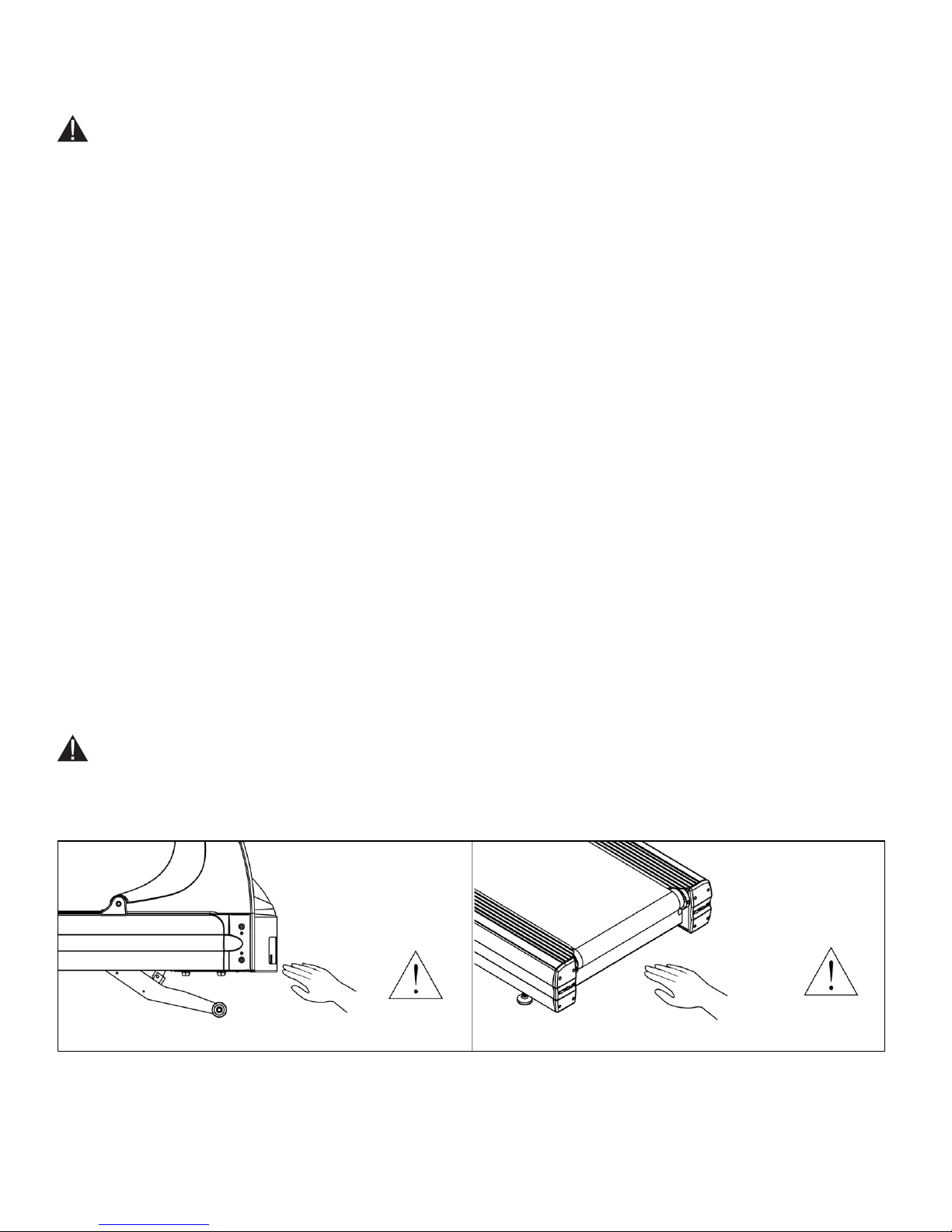
WARNING: Risk of personal injury-crushing hazard when treadmill is in operation - Keep feet, hands, and
fingers away from moving parts.
CAUTION:
• Health related injuries may result from incorrect or excessive use of exercise equipment.
• Do not use typing or web surfing features at excessive speeds. Always stabilize yourself by holding a stationary
handle when using typing or web surfing features. (Varies by console option)
• Do not use the contact heart rate grips as a handlebar during a workout.
• Any changes or modifications to this equipment could void the product warranty.
• To disconnect, turn power OFF at the ON/OFF switch if applicable, then remove plug from electrical outlet.
• Never operate a TRUE product if it has a damaged power cord or electrical plug, or if it has been dropped,
damaged, or even partially immersed in water. Contact TRUE Customer Service for a replacement.
• Use a TRUE AC power cord or AC/DC adapter only.
• *Note the plug configuration for the power adapter may vary by country.
• Position this product so the power cord plug is accessible to the user.
• Keep the power cord away from heated surfaces. Do not pull the equipment by the power cord or use the cord as a
handle. Do not run the power cord along the side or under the treadmill.
• If the electrical supply cord is damaged it must be replaced by the manufacturer, an authorized service agent, or a
similarly qualified person to avoid a hazard.
• Do not use this product in areas where aerosol spray products are being used or where oxygen is being
administered. Such substances create the danger of combustion and explosion.
• Always follow the console instructions for proper operation.
• Close supervision is necessary when used near children under the age of 15, or disabled persons.
• Do not use this product outdoors, near water, while wet, or in areas of high humidity including extreme
temperature changes
• Never operate a TRUE product with the air openings blocked. Keep air openings free of lint, hair or any
obstructing material.
• Never insert objects into any openings in this product. If an object should drop inside, turn off the power, unplug
the power cord from the outlet and carefully retrieve it. If the item cannot be reached, contact TRUE Customer
Service.
• Never place liquids of any type directly on the unit except in the accessory tray or bottle holders. Containers with
lids are recommended.
• Wear shoes with rubber or high traction soles. Do not use shoes with heels, leather soles, cleats or spikes. Make
sure no stones are embedded in the soles. Do not use this product in bare feet. Keep all loose clothing, shoelaces
and towels away from moving parts.
• Do not reach into or underneath the unit, or tip it on its side during operation.
Truefitness.com / 800.426.6570 / 636.272.7100 2
Page 7
CHAPTER 1: SAFETY INSTRUCTIONS
CAUTION (continued):
• Use correct ergonomic positioning while running on treadmill.
• Do not allow animals on or near the equipment while in operation.
• Use the side handrails whenever additional stability is required. In case of emergency, such as tripping, the side
handrails should be grabbed and the user should place his/her feet on the side platforms. The front handlebars
should be used to grasp the heart rate sensors or to rest the hand on while operating the activity zone keys, but not
for stability, emergency, or continuous use.
• Do not exceed maximum user weight of 400 lbs (181 kg).
• Do not use if you have a cold or fever.
• When using this exercise machine, basic precautions should always be followed.
• Use this equipment only for its intended use as described in this manual.
• Do not use attachments not recommended by the manufacturer.
• Allow only trained personnel to service this equipment.
• Avoid the possibility of bystanders being struck or caught between moving parts by making sure that they are out
of reach of the equipment while it is in motion.
• This appliance can be used by children aged from 8 years and above and persons with reduced physical, sensory or
mental capabilities or lack of experience and knowledge if they have been given supervision or instruction
concerning use of the appliance in a safe way and understand the hazards involved.
• Children shall not play with the appliance.
• Cleaning and user maintenance shall not be made by children without supervision.
• Allow only one person at a time on the equipment while it’s operating.
• It is the sole responsibility of the owner/operator to ensure regular and scheduled maintenance is performed.
• To avoid injury stand on the side rails before starting the treadmill.
• Avoid exiting treadmill while leaving the tread belt in motion.
• Never walk or jog backwards on the treadmill.
CAUTION:
• To avoid serious injury, do not touch the incline rack while the treadmill is in use.
• To avoid serious injury, do not touch the belt while the treadmill is in use.
Truefitness.com / 800.426.6570 / 636.272.7100 3
Page 8
CHAPTER 1: SAFETY INSTRUCTIONS
3 2 1
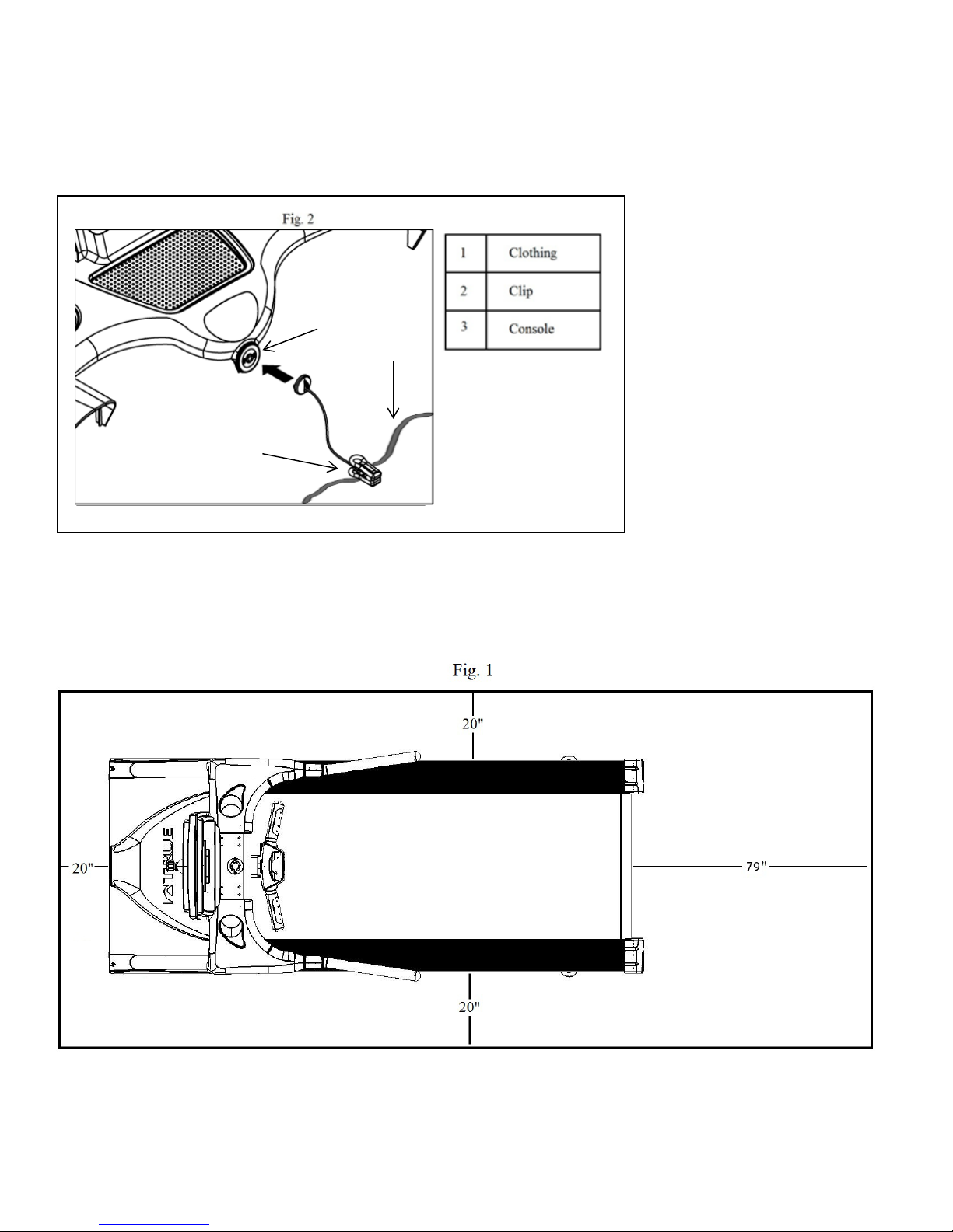
USE OF SAFETY KEY (E-STOP):
• Attach the safety clip to your clothing before each workout and when treadmill is in use. (See Fig 2)
• Attach the magnetic key to the treadmill console assembly.
SPACE REQUIREMENTS:
Space Requirements:
ASTM (USA) and EN (European) regulations require a minimum of 20” (0.5m) on each side of the treadmill and a 79” (2
m) safety zone at the rear of the treadmill. (See Fig 1)
Truefitness.com / 800.426.6570 / 636.272.7100 4
Page 9
CHAPTER 1: SAFETY INSTRUCTIONS
GROUNDING INSTRUCTIONS:
This product must be grounded, if it should malfunction or breakdown, grounding provides a path of least resistance for
electric current to reduce the risk of electric shock. This product is equipped with a cord having an equipment-grounding
conductor and a grounding plug. The plug must be plugged into an appropriate outlet that is properly installed and
grounded in accordance with all local codes and ordinances.
DANGER
• Improper connection of the equipment-grounding conductor can result in a risk of electric shock.
• Check with a qualified electrician or serviceman if you are in doubt as to whether the product is properly
grounded. Do not modify the plug provided with the product. If it will not fit the outlet, have a proper outlet
installed by a qualified electrician.
• Do not remove the motor cover or you may risk injury due to electric shock.
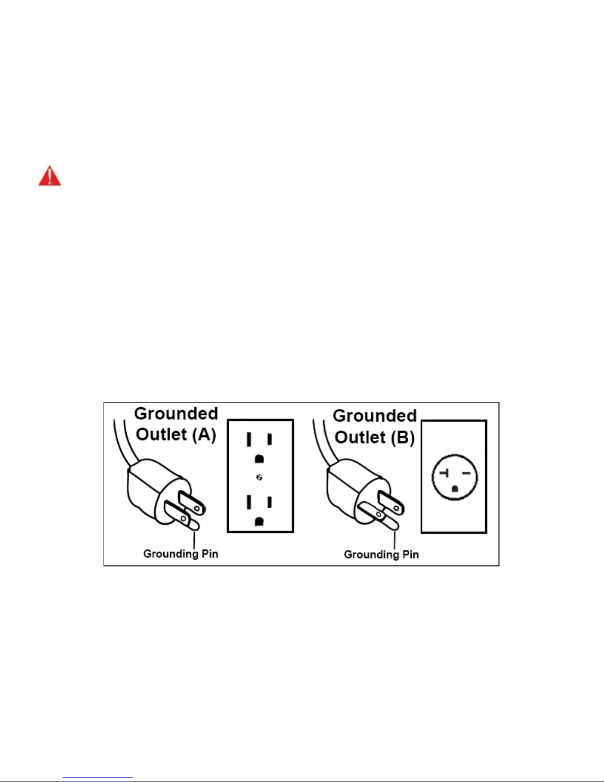
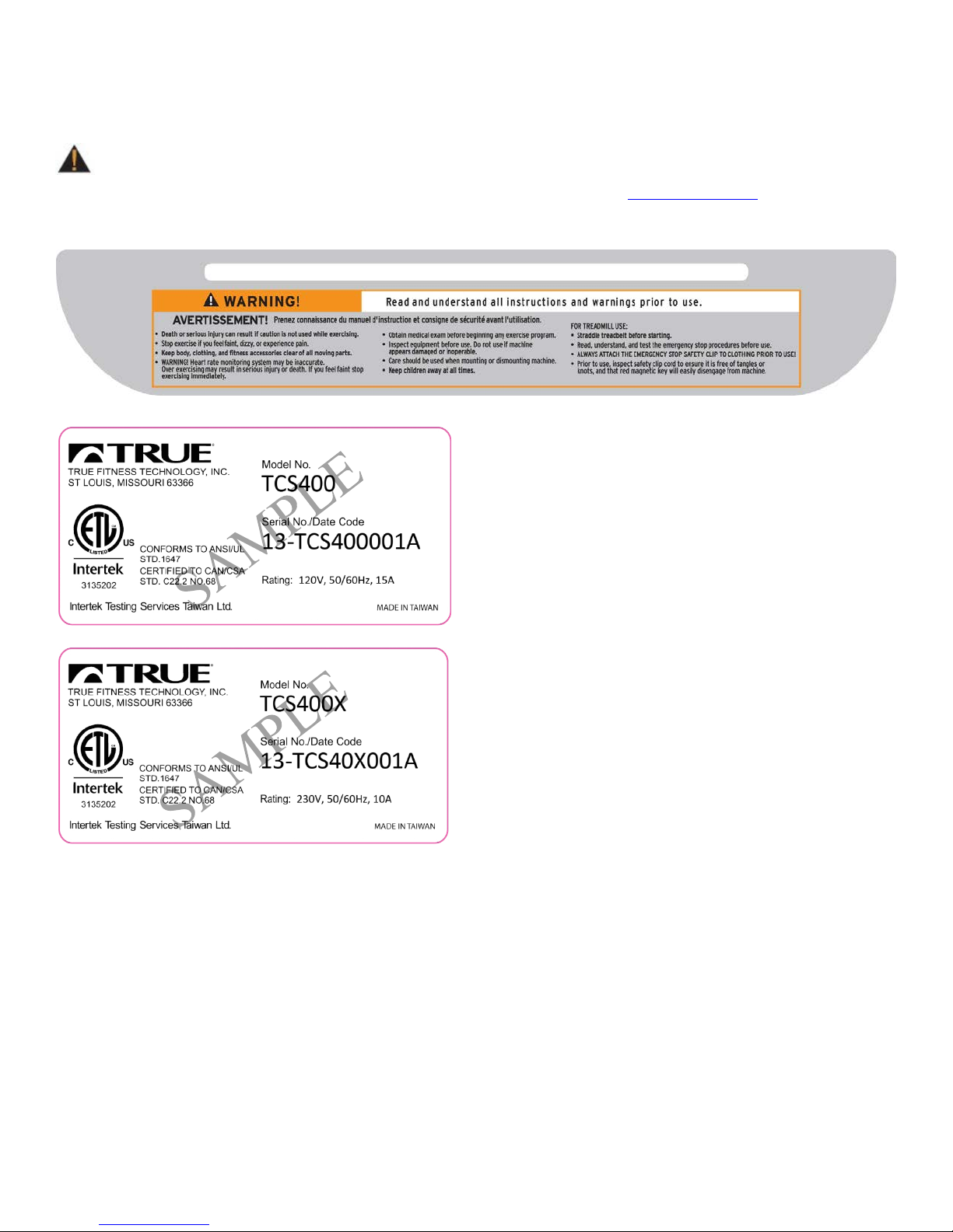
• The 120-V model is for use on a nominal 120-V circuit and has a grounding plug that looks like the plug
illustrated in figure A. Make sure the product is connected to an outlet having the same configuration as the plug.
No adaptor should be used with this product.
• The 230-V model is for use on a circuit having a nominal rating more than 120-V and is factory-equipped with a
specific electric cord and has a grounding plug that looks like the plug illustrated in figure B. Make sure that the
product is connected to an outlet having the same configuration as the plug in Figure B. No adapter should be
used with this product. If the product must be reconnected for use on a different type of electric circuit, the
reconnection should be made by qualified service personnel.
:
Truefitness.com / 800.426.6570 / 636.272.7100 5
Page 10
CHAPTER 1: SAFETY INSTRUCTIONS
Truefitness.com / 800.426.6570 / 636.272.7100 6
Page 11
CHAPTER 1: SAFETY INSTRUCTIONS
WARNING DECALS:
WARNING: Replace warning labels that may be worn, damaged or missing.
To replace any worn or missing warning decals contact TRUE FITNESS by visiting www.truefitness.com
customer service at 800-883-8783.
or contact
COMPLIANCES:
This equipment complies with all applicable codes and regulations. For a complete list of compliances, please visit
www.truefitness.com.
Truefitness.com / 800.426.6570 / 636.272.7100 7
Page 12

CHAPTER 2: ASSEMBLY INSTRUCTIONS
• Read and understand all instructions and warnings prior to use.
• Save these instructions.
IMPORTANT SAFETY INSTRUCTIONS
• Obtain a medical exam before beginning any exercise program. If at any time during exercise you
feel faint, dizzy, or experience pain, stop and consult your physician.
• Obtain proper instruction prior to use.
• This treadmill is intended for light commercial use only.
• Inspect the treadmill for incorrect, worn, or loose components and do not use until corrected,
replaced, or tightened prior to use.
• Do not wear loose or dangling clothing while using the treadmill.
• Care should be used when mounting or dismounting the treadmill.
• Read, understand, and test the emergency stop procedures before use.
• Disconnect all power before servicing the treadmill.
• Do not exceed maximum user weight of 400 lbs.
• Keep the top side of the moving surface clean and dry.
• Keep children and animals away.
• Use caution when moving and assembling treadmill.
• All exercise equipment is potentially hazardous. If attention is not paid to the conditions of
equipment usage, death, or serious injury could occur.
Basic Guidelines for Setting Up Your Treadmill:
After removing the treadmill from the packaging, place your treadmill on a clean, level surface. Make sure the electrical
cord easily reaches a grounded three-pronged outlet and has enough slack to allow the deck to incline without tightening
the cord. Do not allow the treadmill assembly to rest on the cord.
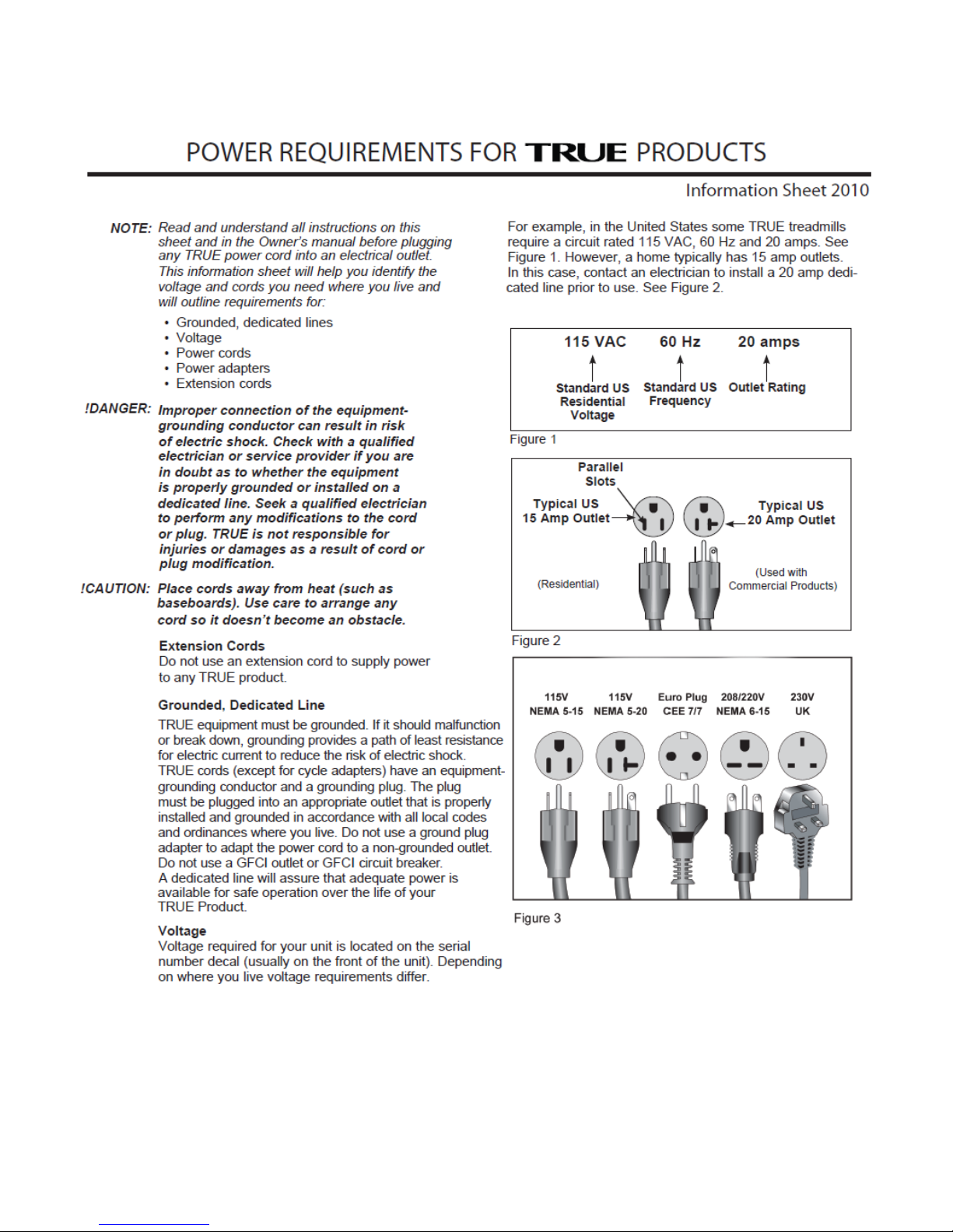
Important Electrical Requirements – 120V:
Your TRUE treadmill requires a dedicated 120 volt, alternating current (AC), 20 amp grounded outlet circuit. This means
nothing else can be plugged into the same circuit. Most power circuits are rated for this 120V AC 20 amp requirement, but
you must ensure the treadmill does not share the circuit with anything else.
Important Electrical Requirements – 230V
Your TRUE treadmill requires a dedicated 230 volt, alternating current (AC), 15 amp grounded outlet circuit. This means
nothing else can be plugged into the same circuit. Most power circuits are rated for this 230V AC 15 amp requirement, but
you must ensure the treadmill does not share the circuit with anything else.
Danger: Do not use an extension cord or ungrounded outlet.
The ground helps prevent electrical damage to your treadmill and enhances your safety by helping to prevent shock.
Check with a qualified electrician or serviceman if you are in doubt as to whether the treadmill is properly grounded. Do
not modify the plug provided with the treadmill if it will not fit the outlet. Have a proper outlet installed by a qualified
electrician.
Truefitness.com / 800.426.6570 / 636.272.7100 8
Page 13
CHAPTER 2: ASSEMBLY INSTRUCTIONS
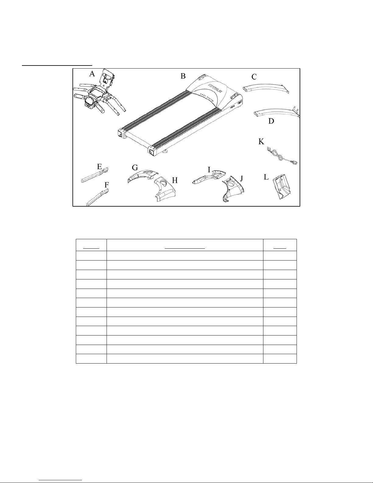
Item
Description
Qty
A
Console Rack
1
B
Frame
1
C
Pedestal (L)
1
D
Pedestal (R)
1
E
Handrail (L)
1
F
Handrail (R)
1
G
Shoulder Cover-Top (L)
1
H
Shoulder Cover-Top I)
1
I
Shoulder Cover – Bottom (L)
1
J
Shoulder Cover – Bottom (R)
1
K
Power Cord
1
L
Console Cover
1
PRE-ASSEMBLY CHECK LIST:
Frame Components:
Truefitness.com / 800.426.6570 / 636.272.7100 9
Page 14
CHAPTER 2: ASSEMBLY INSTRUCTIONS
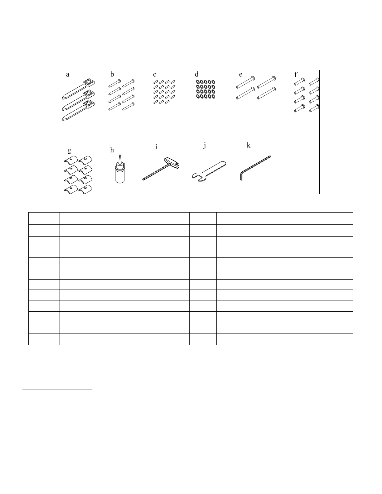
Item
Description
Qty
Where Used
a
Wire Tie
3
Cables
b
Bolt M8 x 1.25 x 75mm
8
Pedestals
c
Screw M4 x 0.7 x 10mm
19
Shoulder Cover-Top and Bottom
d
Washer M8 - Internal Tooth
20
Various
e
Bolt M8 x 1.25 x 80mm
4
Hand Rails
f
Bolt M8 x 1.25 x 40mm
8
Console Rack
g
Shoulder Plates
8
Console Rack
h
Tread Belt Lubricant
1
Under Tread belt
i
T- Spanner – 8mm
1
Tread Belt Adjustment
j
Wrench 17mm
1
Hex Head Bolt – Pedestal Front
k
Hex Key – 5mm
1
Various
PRE-ASSEMBLY CHECK LIST (continued):
Hardware Pack:
NOTE: Consult your TRUE Fitness TCS400 Treadmill Owner’s Manual for information related to item (h) Tread Belt
Lubricant for Tread Belt lubrication procedure and item (i) T-Spanner – 8mm for Tread belt Adjustment.
Tool Requirements:
• Hex Key – 5mm, T-Spanner-8 mm, Wrench 17mm (included with hardware kit)
• 7/16 Open End Wrench (not included)
• Long Nose Pliers (not included)
• #2 Phillips Screwdriver (not included)
Truefitness.com / 800.426.6570 / 636.272.7100 10
Page 15
CHAPTER 2: ASSEMBLY INSTRUCTIONS
TREADMILL ASSEMBLY STEPS:
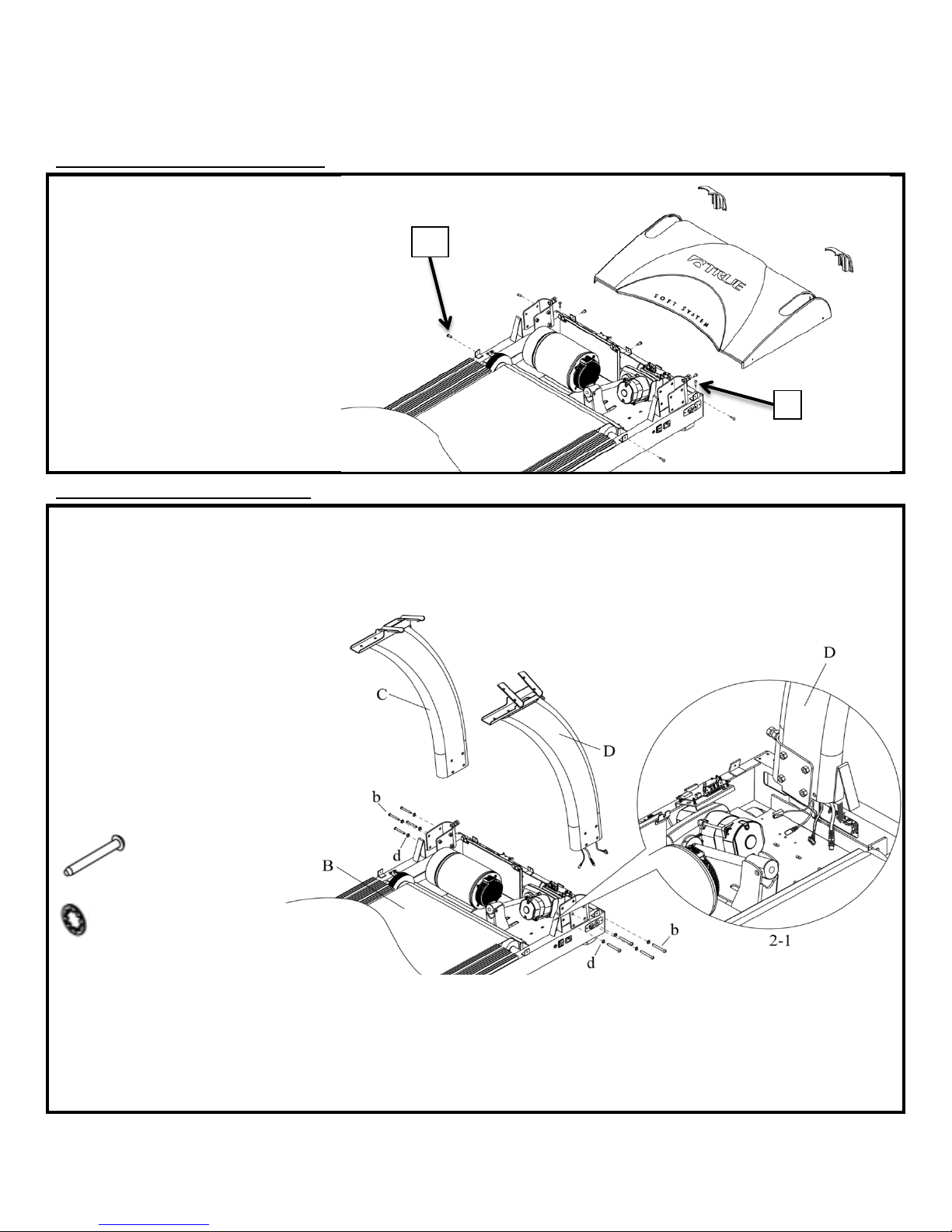
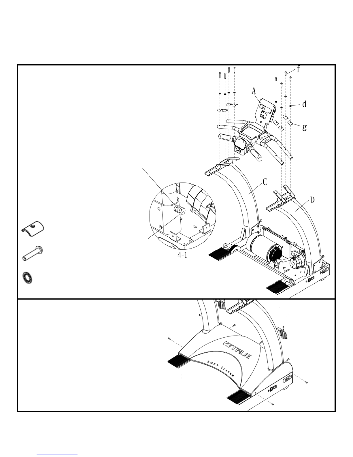
STEP 1: Remove Motor Cover:
a) Remove two screws (l) and two
STEP 2: Pedestal Installation:
a) Check that Hex Head Bolts in Fig
m
Motor Decoration Covers from
Frame.
b) Remove seven screws (m) and
Motor Cover from Frame.
c) Set hardware to the side for use in
step 4.
2-1 are backed out enough to clear
Pedestals when installed.
b) Install Pedestal – R (D) into
pedestal support on Frame (B) while
pulling four cables out of pedestal
support as shown in Fig. 2-1.
NOTE: Be careful not to pinch cables.
c) Install Pedestal – L (C) into
pedestal support on Frame.
d) Using 5mm Hex Key, install but do
not tighten eight Bolts-M8 x 75mm
(b) and Washers-M8 (d) as shown .
Required Hardware:
8 M8 x 75mm Bolts (b)
8 Internal Tooth M8 Washers (d)
Truefitness.com / 800.426.6570 / 636.272.7100 11
Page 16
CHAPTER 2: ASSEMBLY INSTRUCTIONS
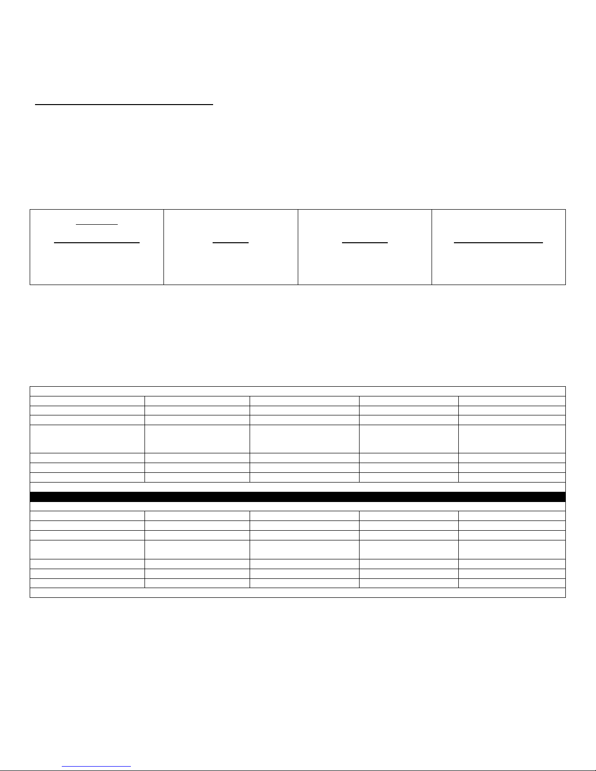
Emerge
2 Window LED
Escalate
9”TFT
Escalate
15” TFT
Transcend
10”Touchscreen
Step 3-2A
Step 11A
Step 3-2A
Step 11A
Step 3-2B
Step 11B
Step 3-2B
Step 11B
TCS400 TREADMILL FRAME CABLE CONNECTONS 110V
Pedestal Cable or Power Supply
15”TFT non Touchscreen
10” LCD with Touchscreen
9” TFT no Touchscreen
2 window LCD
CNTRL CABLE
YES
YES
YES
YES
COAX CABLE
YES
YES
YES
YES
REQUIRED – SHIPPED WITH
CUSTOMER INSTALLS
REQUIRED – SHIPPED WITH
INSTALLS
COMM CABLE
YES
YES
YES
YES
CNTRL to AUXPS
NO
NO
YES
YES
TCPS POWER CORD to AUSPS
YES
YES
NO
no
YES = MAKE CABLE CONNECTION NO = DO NOT CONNECT N/A = NOT APPLICABLE
TCS400 TREADMILL FRAME CABLE CONNECTONS 220V
Pedestal Cable or Power Supply
15”TFT non Touchscreen
10” LCD with Touchscreen
9” TFT no Touchscreen
2 window LCD
CNTRL CABLE
YES
YES
YES
YES
COAX CABLE
YES
YES
YES
YES
AUXILIARY POWER SUPPLY
REQUIRED- INSTALLED IN
TREADMILL FROM FACTORY
REQUIRED- INSTALLED IN
TREADMILL FROM FACTORY
COMM CABLE
YES
YES
YES
YES
CNTRL to AUXPS
NO
NO
YES
YES
TCPS POWER CORD to AUSPS
YES
YES
NO
no
YES = MAKE CABLE CONNECTION NO = DO NOT CONNECT N/A = NOT APPLICABLE
TREADMILL ASSEMBLY STEPS (continued):
Important Display Specification:
Verify on customer product order what type of display will be installed on this treadmill.
Listed below are the four display options for these series of treadmills.
Find the correct Display Option for assembly and follow frame cable routing (step 3) directions for either section 3-2A or
3-2B and for console cable connections (step 11) follow section 11A or 11B
NOTE: Cables will be labeled near their connector with identifying names such as those listed in BOLD TEXT throughout
these instructions.
NOTE: See TCS400 Treadmill Frame Cable Connection Table below for 120V or 230V cable connections summary.
AUXILIARY POWER SUPPLY
DISPLAY CONSOLE.
DISPLAY CONSOLE. CUSTOMER
N/A N/A
N/A N/A
NOTE: Reference Wiring Schematic and Frame Cable Routing Diagram contained in these assembly instructions. You
may remove from packet to aid in assembly but if you remove we recommend you retain these diagrams with the
instructions for future reference.
Truefitness.com / 800.426.6570 / 636.272.7100 12
Page 17
CHAPTER 2: ASSEMBLY INSTRUCTIONS
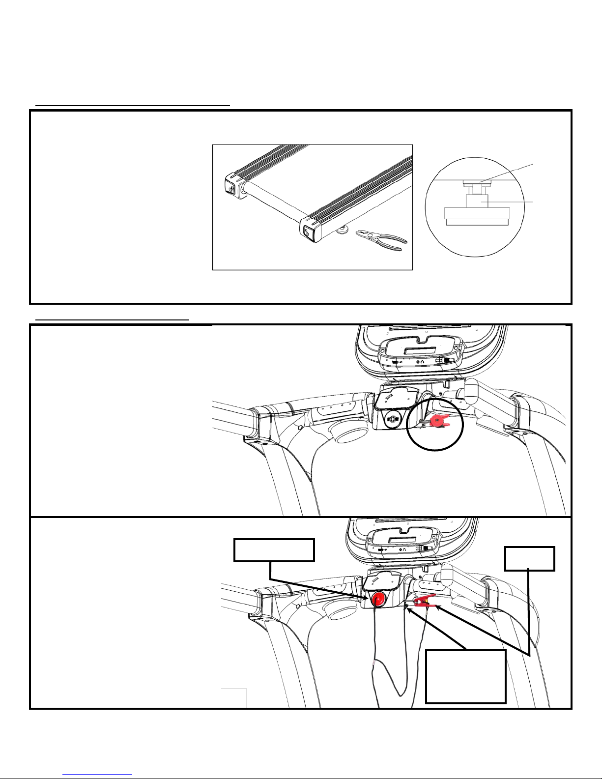
TREADMILL ASSEMBLY STEPS (continued):
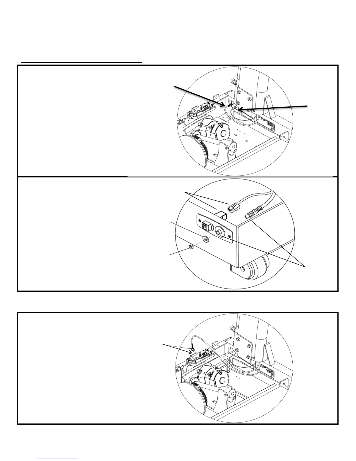
STEP 3-1: Frame Cable Connections:
a) Route the COAX Cable and
b) Connect the COMM cable to the
Step 3-2A Frame Cable Connections:
a) Ensure the AUXPS cables that are
Washer
Nut
Connect COMM
Cable Here
Pass COAX Cable
Through Here
Make CNTRL /AUXPS
COMM Cable to the front of the
treadmill frame.
network jack on the power plate as
shown.
c) Remove nut and washer from front
of COAX Cable as shown.
d) Pass front of COAX Cable through
hole in electrical panel and install
washer and tighten nut using 1/2 inch
open end wrench on nut and long
nose pliers on connector portion of
cable.
*LED CONSOLES & 9” TFT CONSOLES ONLY
attached to the CNTRL cable are
firmly connected.
b) Connect the CNTRL / AUXPS
cable bundle to the smart board as
shown.
Truefitness.com / 800.426.6570 / 636.272.7100 13
Connection Here
Page 18
CHAPTER 2: ASSEMBLY INSTRUCTIONS
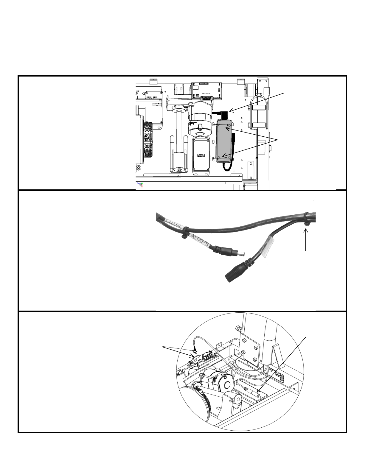
TREADMILL ASSEMBLY STEPS (continued):
*TOUCHSCREEN CONSOLES & 15” TFT CONSOLES ONLY
a) Place Auxiliary Power Supply
d) Separate the AUXPS cables that are
e
AUXPS Connection
Made
Make CNTRL
Connection Here
Wire Ties
TCPS Power Supply
Connector
Cut Wire Tie
Step 3-2B Frame Cable Connections:
(included in console box), in motor
area floor location shown.
b) Connect TCPS Power Supply AC
connector (large connector w/ 3 pins)
into Auxiliary Power Supply as shown
in picture. Make sure connector is
fully inserted.
c) Secure Auxiliary Power Supply to
floor using the supplied wire ties.
NOTE: The Auxiliary Power Supply
will be pre-installed in 220v units.
attached to the CNTRL cable and cut
the wire tie holding the female end of
the AUXPS cable to the CNTRL cable
as shown.
) Connect the female end of the
AUXPS Cable coming from Pedestal
to AUXPS Power Supply Cable.
f) Connect the CNTRL cable to the
smart board as shown
NOTE: The male end of the AUXPS
cable wire tied to the CNTRL cable is
not used for this installation.
Truefitness.com / 800.426.6570 / 636.272.7100 14
Page 19
CHAPTER 2: ASSEMBLY INSTRUCTIONS
TREADMILL ASSEMBLY STEPS (continued):
STEP 4: Console Rack and Motor Cover Installation:
a) Install Console Rack (A) onto
e
Hex Nut
Hex Screw
Pedestals R & L by resting Console
Rack tubing on top of Pedestal tubing
cradles.
b) Using 5 mm Hex Key, install but
do not tighten, 8 Shoulder Plates (g),
8 Bolts-M8 x 40mm (f) and 8 external
tooth washers (d) through Console
Rack tubing and into Pedestal tubing
cradles. Once all eight bolts are
installed, tighten all bolts.
c) Tighten the 8 Bolts that secure
Pedestals to Frame. (see step 2)
d) Use a 17mm wrench to tighten two
Hex Head Bolts until secure against
Pedestal legs. Then tighten two nuts
to secure Hex Head Bolts. See Fig 4-1.
Required Hardware:
8 Shoulder Plates (g)
8 M8 x 40mm Bolts (f)
8 Internal Tooth M8 Washers (d)
) Place Motor Cover onto frame.
Using a Phillips Screwdriver, install
Motor Cover into Frame with seven
Motor Cover screws. Install Motor
Decoration Covers with two screws as
shown.
Required Hardware:
Hardware from step 1.
Truefitness.com / 800.426.6570 / 636.272.7100 15
Page 20

CHAPTER 2: ASSEMBLY INSTRUCTIONS
TREADMILL ASSEMBLY STEPS (continued):
STEP 5: Console Rack Cable Connections:
a) Connect the COAX, AUXPS,
STEP 6: Handrail Installation:
a) Insert Handrails (E, F) onto
STEP 7: Top Shoulder Covers:
a. Using a Phillips screwdriver, install
AUXPS
CNTRL
COAX
COAX from Rack
CNTRL from Rack
AUXPS from Rack
COMM from Rack
COMM
COMM and CNTRL cables coming
from the right pedestal to the
corresponding wires in the console
rack.
NOTE: All four connections are made
for any Console model.
Pedestals and secure with 4 Bolts -M8
x 80mm (e) and Internal Tooth
Washer M8 (d) using 5 mm Hex Key.
Required Hardware:
4 M8 x 80mm bolts (e)
4 Internal Tooth M8 Washers (d)
Shoulder Cover Top pieces Left (G)
and Right (H) with three Screws M4 x
10mm (c) on each side as shown.
CAUTION: Make sure cabling is
NOT pinched during installation.
Required Hardware:
6 M4 x 0.7 x 10mm screws(c)
Truefitness.com / 800.426.6570 / 636.272.7100 16
Page 21
CHAPTER 2: ASSEMBLY INSTRUCTIONS
TREADMILL ASSEMBLY STEPS (continued):
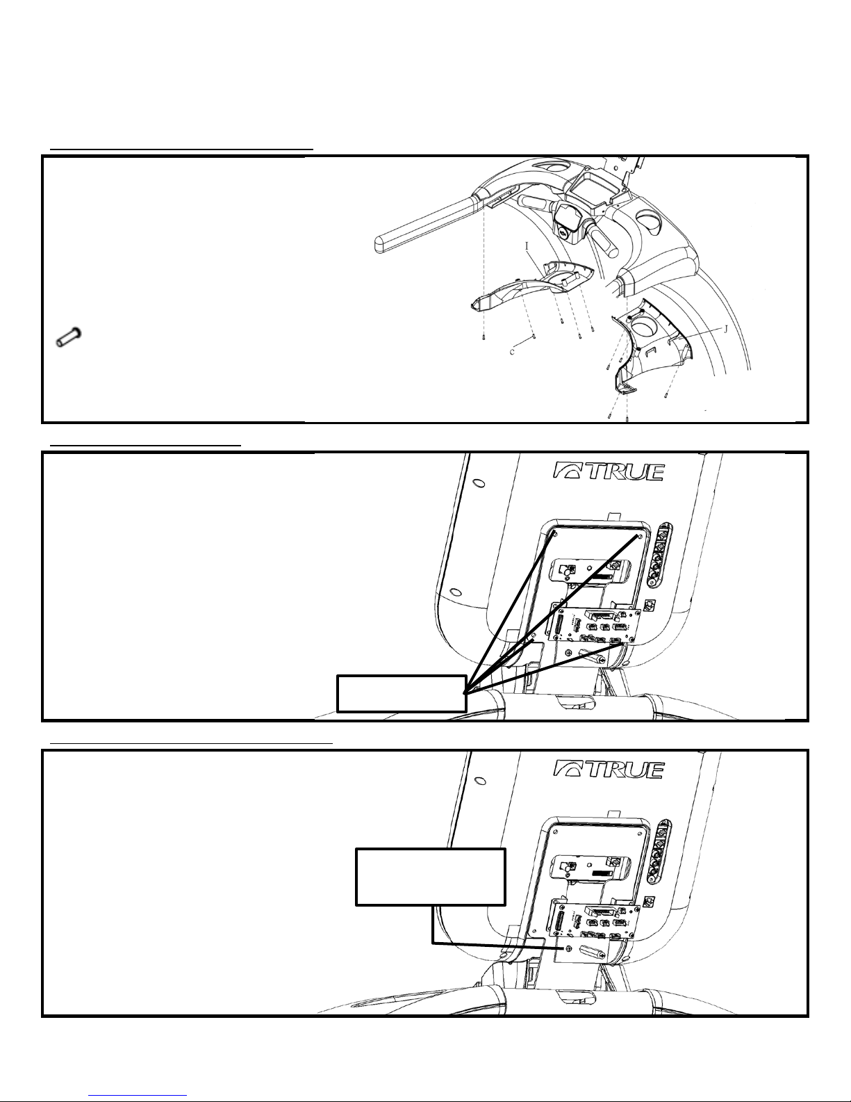
STEP 8: Bottom Shoulder Covers:
a) Using a Phillips screwdriver, install
STEP 9: Attach Console:
a) Attach console to mast using the 4
STEP 10: Ground Wire Connection:
a) Attach ground wire coming from
4 M5x12 screws
Attach console
Shoulder Cover Bottom pieces Left
(G) and Right (H) with five Screws
M4 x 10mm (c) on each side as
shown.
CAUTION: Make sure cabling is
NOT pinched during installation.
Required Hardware:
10 M4 x 10mm screws (c)
M5x12 screws that come with the
console.
Required Hardware:
Included with console.
the back of the console to the ground
screw.
ground wire here
Truefitness.com / 800.426.6570 / 636.272.7100 17
Page 22

CHAPTER 2: ASSEMBLY INSTRUCTIONS
9” TFT Console
Orange LED Console
TREADMILL ASSEMBLY STEPS (continued):
Step 11A Console Cable Connections:
*Follow Step 11A if installing a 9” TFT console or an LED console. For other consoles, proceed to Step 11B.
Connect Data Cable (50-pin)
Both 9” TFT & Orange LED Consoles
Connect Power Cable (2-pin)
9” TFT Console Orange LED Console
NOTE: Ethernet & Coaxial cable connections are not available on the Orange LED or 9” TFT Consoles
All Ground Wires Must be connected
Truefitness.com / 800.426.6570 / 636.272.7100 18
Page 23
CHAPTER 2: ASSEMBLY INSTRUCTIONS
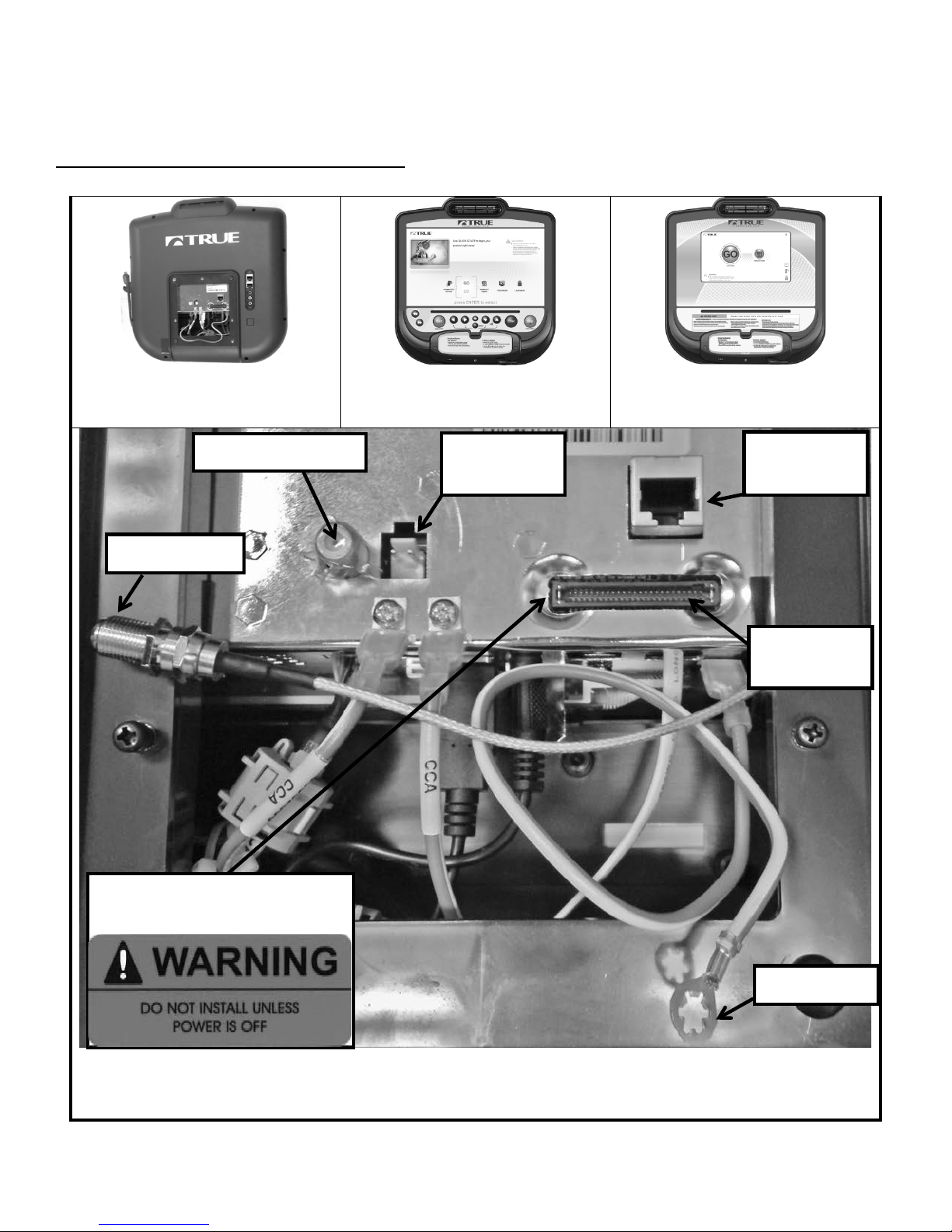
15” TFT
Console
10” Touchscreen
Console
NOTE:
All Ground Wires Must be connected
Power Cable
2 Pin
Network
Cable
Coaxial Cable
Data Cable
(50 Pin)
Ground Wire
Remove Warning Label
Do Not Use
TREADMILL ASSEMBLY STEPS (continued):
STEP 11B: Console Cable Connections:
*Follow Step 11B if installing a touchscreen console or 15”TFT console. . For other consoles, return to Step 11A.
to access data port
Ethernet & Coaxial cable connections are not available on the Orange LED or 9” TFT Consoles
The Ethernet Port on the 15” TFT Console is non-functioning
Truefitness.com / 800.426.6570 / 636.272.7100 19
Page 24
CHAPTER 2: ASSEMBLY INSTRUCTIONS
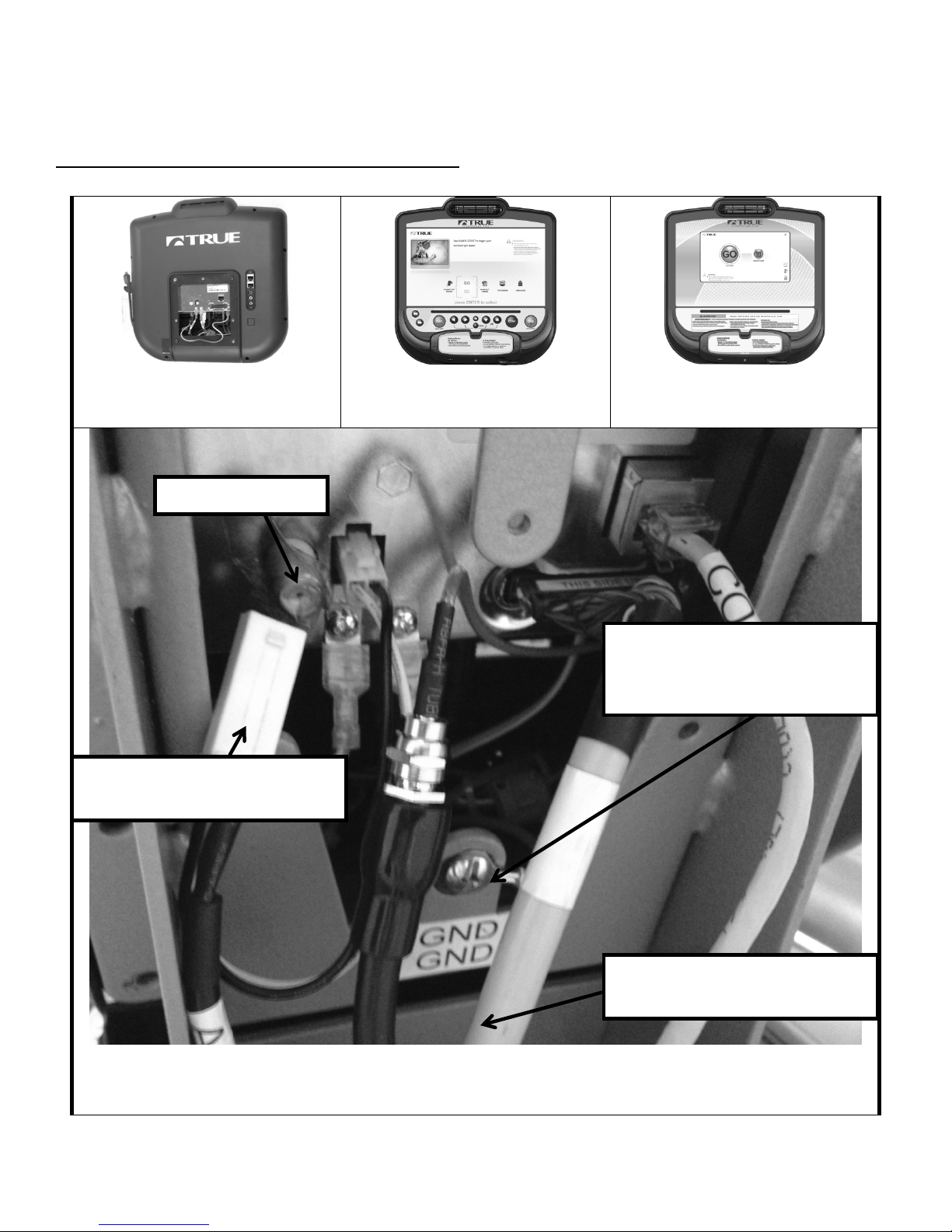
15” TFT
Console
10” Touchscreen
Console
All Ground Wires Must be connected
This connector is only used with
an “Optional TV Mount”
Ensure the Ground Cable is
Tuck excess Cable length into the
Front Mast
Do Not Use
TREADMILL ASSEMBLY STEPS (continued):
STEP 11B (continued): Console Connections:
*Follow Step 11B if installing a touchscreen console or 15”TFT console. . For other consoles, return to Step 11A.
attached by the Ground Screw
*Location Varies By Model
NOTE: Ethernet & Coaxial cable connections are not available on the Orange LED or 9” TFT Consoles
The Ethernet Port on the 15” TFT Console is non-functioning
Truefitness.com / 800.426.6570 / 636.272.7100 20
Page 25

CHAPTER 2: ASSEMBLY INSTRUCTIONS
TREADMILL ASSEMBLY STEPS (continued):
STEP 12: Rear Console Cover:
a) Attach the rear console cover (L)
STEP 13: Power Cord Installation:
a) Insert Power Cord into Power Inlet
CIRCUIT BREAKER: In the event
Power Inlet
(120V Shown)
Power Switch
Circuit Breaker
Coax Cable
Network Port
Circuit Breaker Positions
CLOSED
OPEN
with 3 Screws M4 x 0.7 x 10mm (c) as
shown.
Required Hardware:
3 M4 x 10mm screws (c)
shown to the right.
NOTE: 230V Front Electrical Panel
will appear different from the figure
to the right. The circuit breaker is not
visible and is within Power Switch.
POWER SWITCH: | = ON, 0 = OFF
the current drawn by the treadmill
exceeds a specified threshold value,
the Circuit Breaker will pop out, and
open the circuit. If this should occur,
please wait 10 minutes and then reset
the Circuit Breaker by pressing the
button in on Circuit Breaker. If it does
not reset, or the Circuit Breaker pops
out again, please contact TRUE
Fitness Service department at
1-800-883-8783.
Port
Truefitness.com / 800.426.6570 / 636.272.7100 21
Page 26
CHAPTER 2: ASSEMBLY INSTRUCTIONS
TREADMILL ASSEMBLY STEPS (continued):
STEP 14: Unit Leveling (if needed):
a) Ensure treadmill incline
STEP 15: Attach Safety Key:
NOTE: The safety key and
c) Attach Safety Key magnet to front
LANYARD
TO PLATE
CLIP
MAGNET
A
B
rack wheels and rear feet are
resting on the floor.
b) Using a 15/16 inch
open end wrench, loosen
nut (A) the Rear Foot.
c) Using a level or estimating by
sight, turn section (B) of foot
clockwise, or counter-clockwise,
using a 7/8 inch open end wrench to
level the unit.
d) Tighten nut (A) until it is secured
against bottom of treadmill.
attachment cord are wrapped around
plate during shipping as shown.
a) Unwind safety key and cord from
plate.
of Center Pod as shown.
d) Attach Safety Key clip to plate
located on Console Rack (when not
working out).
e) Attach clip to clothing at the
beginning of any workout.
CAUTION: Read treadmill Owner’s
Manual before attempting any
workout.
ATTACHED
Truefitness.com / 800.426.6570 / 636.272.7100 22
Page 27
CHAPTER 2: ASSEMBLY INSTRUCTIONS
TREADMILL ASSEMBLY STEPS (continued):
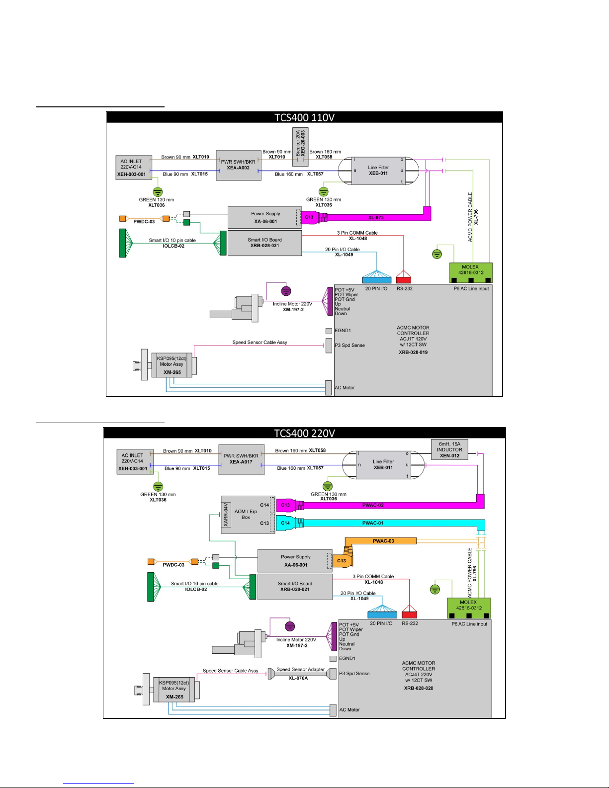
110V Wiring Diagram:
220V Wiring Diagram:
Truefitness.com / 800.426.6570 / 636.272.7100 23
Page 28
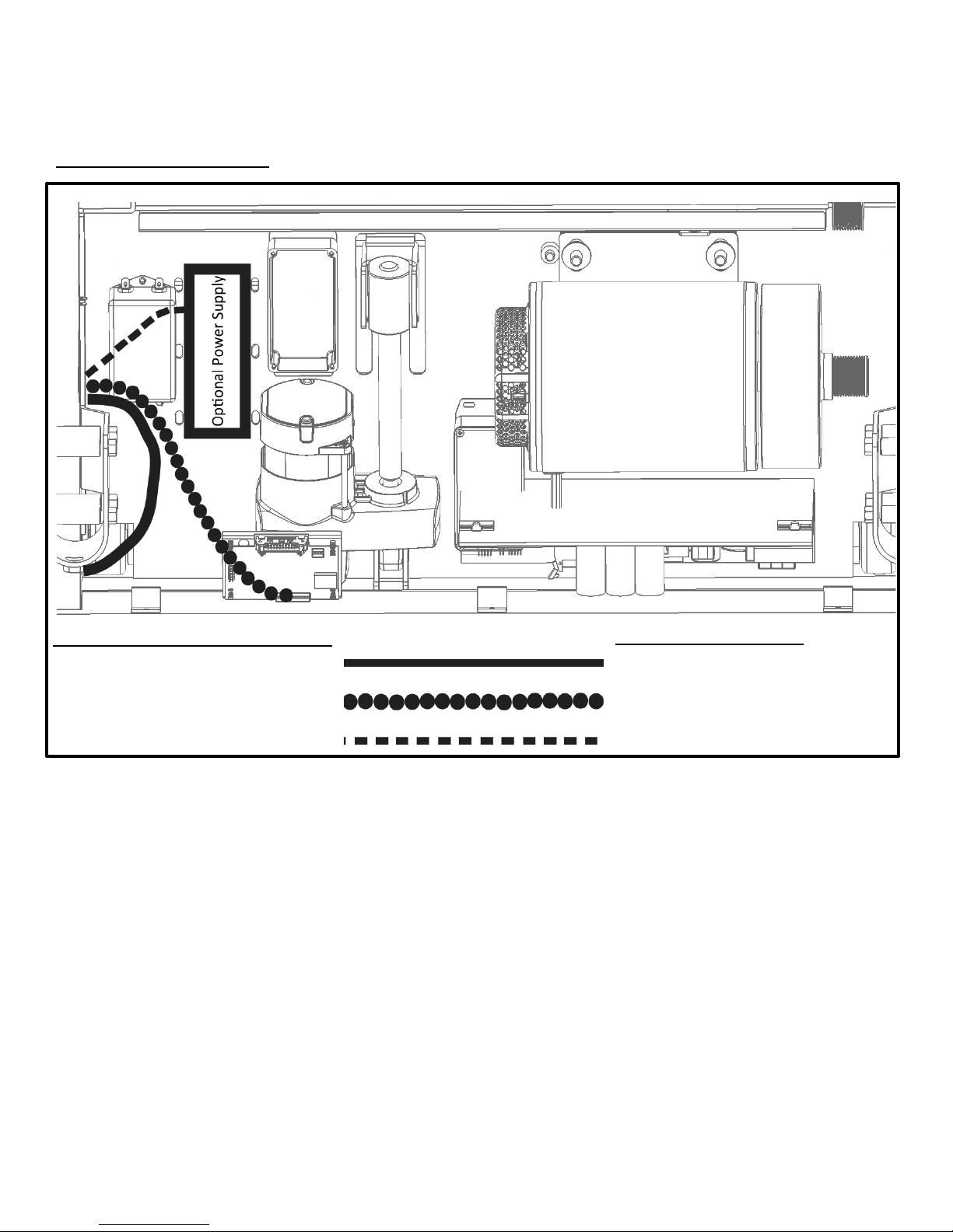
CHAPTER 2: ASSEMBLY INSTRUCTIONS
Touchscreen or 15”TFT Console
AUXPS Cable
9”TFT or LED Console
N/A
TREADMILL ASSEMBLY STEPS (continued):
Cable Routing Diagram:
COAX & COMM Cables
CNTRL Cable
COAX & COMM Cables
CNTRL/AUXPS Cable Bundle
Truefitness.com / 800.426.6570 / 636.272.7100 24
Page 29
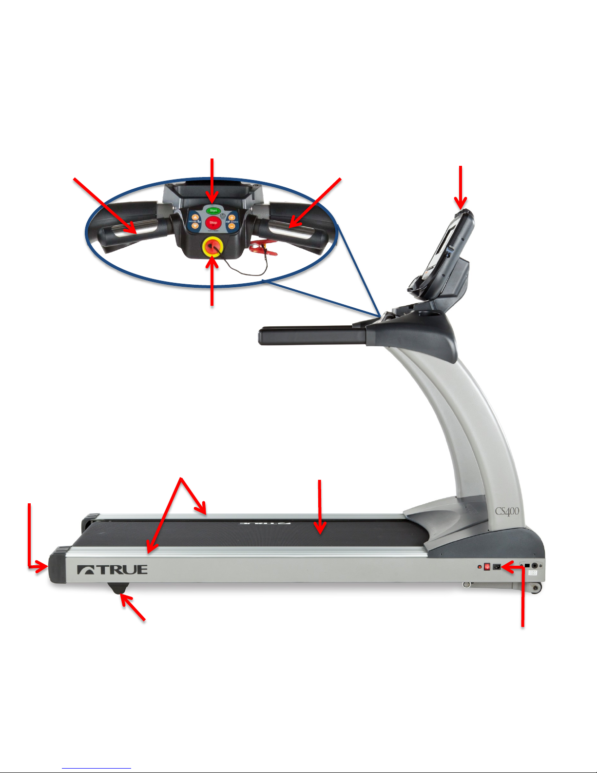
CHAPTER 3: PRODUCT OVERVIEW
Console Assembly
Straddle Covers
Belt
Leveling Feet
On/Off Switch,
Power Cord
Belt Adjustment
Contact Heart
Rate Pad
Contact Heart
Rate Pad
Safety (E-Stop)
Key
Quick Access
Keys
TREADMILL OVERVIEW:
Bolts
Truefitness.com / 800.426.6570 / 636.272.7100 25
Circuit Breaker, and
Page 30

CHAPTER 3: PRODUCT OVERVIEW
TREADMILL OVERVIEW (continued):
Console Assembly:
The console allows the user to set up a workout program and control the treadmill during a workout (For console
overview and operation instructions refer to chapter 4).
Quick Access Keys:
Allows the user to quickly start, stop and wake the treadmill or make fast, convenient adjustments to the incline level or
speed of the treadmill.
Contact Heart Rate Pads:
Allows the user to check their heart rate without wearing a wireless chest strap.
*For increased safety and accuracy this feature should only be used when the belt speed is below 4 mph.
Safety (E-Stop) Key:
A tethered safety device designed to attach to both the user and the treadmill console. Removal of the key from the console
will stop belt motion to prevent injury in an emergency.
*The safety key must be in place on the treadmill, and should be attached to the user’s clothing. The treadmill will not
operate if the safety key is not attached to the treadmill.
Belt:
The moving surface of the treadmill on which the user walks or runs.
Straddle Covers:
Stationary covers on either side of the belt, which allows the user to safely straddle the belt during startup or in the event of
an emergency.
Belt Adjustment Bolts:
An adjustment system that allows the users to adjust the belt tracking and tension as needed.
On/Off Switch:
Allows users or faculty to turn the power on or off to the treadmill.
Circuit Breaker:
A safety device designed to protect the treadmill from excessive electrical current.
Power Cord:
Delivers power from the wall outlet to the treadmill.
Leveling Feet:
An adjustable system used to aid in the leveling the treadmill.
Truefitness.com / 800.426.6570 / 636.272.7100 26
Page 31

CHAPTER 4: PROGRAMMING & OPERATION
CAUTION:
The safety key must be in place on the treadmill console, and should be attached to the user’s clothing. The treadmill will
not operate if the safety key is not attached to the console.
HEART RATE MONITORING:
This treadmill can monitor a user’s heart rate using either a Polar® compatible chest strap or the metal grips on the hand
rails (called contact heart rate or CHR pads). A chest strap transmits the user’s heart rate to the treadmill via radio, and the
CHR pads connect to a special computer circuit to extract the user’s heart rate.
Chest Strap Heart Rate Monitoring:
Although this treadmill functions fine without using the heart rate monitoring feature, this
kind of monitoring gives valuable feedback on the user’s effort level. Chest strap monitoring
also allows users to use Heart Rate Control, the most advanced exercise control system
available.
When users wear a Polar® compatible transmitter strap, the treadmill will display the user’s
heart rate as a digital beats-per-minute (bpm) readout.
The transmitter strap should be worn directly against the user’s skin, about 1-2 inches
below the pectoral muscles/breast line. Women should be careful to place the
transmitter below their bra line.
Initially the transmission signal for heart rate may be erratic or non-existent. Some moisture is
necessary between the strap and the user’s skin for proper transmission. Sweat from exercise
works best, but ordinary tap water may be used prior to the workout if desired.
A Note on Chest Strap Heart Rate Monitoring:
The chest strap produces a radio signal that the treadmill reads and registers as the user’s heart rate. The accuracy of a
reading may be affected when outside interference is present.
Contact Heart Rate (CHR):
The CHR system will let the user monitor their heart rate without wearing a chest strap. When using the CHR system
users should gently grasp the CHR pads with both hands. Within 30 seconds, the user’s heart rate should be displayed as a
digital bpm readout (during the first 30 seconds the system is analyzing and locking in the user’s heart rate). Users should
exercise with smooth body motions and breathe regularly. It is best to avoid talking while using the CHR system, as
talking will cause unrepresentative heart rate spikes of 5 to 10 bpm. To ensure an accurate reading, the user’s hands should
be clean, free of both dirt and hand lotions.
*For increased safety and accuracy the CHR system should only be used at speeds of 4 mph or lower (CHR readings are
less accurate due to large muscle movements above this speed).
A Note on CHR Accuracy:
CHR monitoring may be less accurate than chest strap monitoring since the heart rate signals are much stronger at the
chest. When using a HRC workout, it is best to use a chest strap because of the stronger and more accurate readings.
CAUTION:
Do not use the contact heart rate grips as a handlebar during a workout.
Truefitness.com / 800.426.6570 / 636.272.7100 27
Page 32

CHAPTER 4: PROGRAMMING & OPERATION
HEART RATE CONTROL (HRC):
Introduction:
You are now the owner of the most sophisticated Heart Rate Control treadmill available. TRUE HRC is unique and
patented. It accommodates users from rehabilitation to world class athletes, and all those in between. TRUE HRC allows
users to do a completely hands free heart rate controlled workout using speed, incline or both. By training at a specific
target heart rate, users can exercise at a more efficient cardiovascular level.
The TRUE HRC system is unique because users must enter the key parameters of the workout; target heart rate,
maximum speed, maximum incline, and time, prior to beginning the HRC workout. As users approach their target heart
rate, the treadmill’s computer automatically takes over and changes the speed and/or incline automatically to keep users
near their target heart rate. This allows for a completely “hands free” workout.
*A Polar® compatible heart rate monitoring chest strap should be worn during HRC workouts. For increased safety and
accuracy, contact heart rate monitoring is not recommended for HRC workouts.
Target Heart Rate:
TRUE’s heart rate control (HRC) workouts let the treadmill monitor relative exercise intensity by way of the user’s heart
rate, then automatically adjust the speed and incline to keep the user at their target heart rate and thus their desired
exercise intensity. Heart rate is a good measure of the body’s exercise stress level. It reflects differences in physical
condition, fatigue, the comfort of the workout environment, even diet and emotional state. Users should compare their
heart rate with how they feel to ensure safety and comfort.
Consult a physician to determine target heart rate:
Using heart rate to control a workout takes the guesswork out of the workout settings. Consult a physician before using
heart rate controlled workouts for advice on selecting a target heart rate range. Also, it is important to use the treadmill for
several workouts in the manual mode while monitoring heart rate. Users should compare their heart rate with how they
feel to ensure safety and comfort. After users have spent some time learning how their heart responds to different levels of
speed and incline, they will have a better understanding of how to select the maximum speed and maximum incline
required for reaching their target heart rate.
Warm Up:
At the beginning of an HRC workout, the treadmill is in full Manual Control mode. Users should gradually increase the
workout intensity to slowly raise their heart rate to within 10 beats per minute (bpm) of their target heart rate. The
treadmill will operate as if in manual mode during the warm up stage. Users control both speed and incline. The user may
only increase speed and incline to the present maximum values entered. It is important that the user starts at a low level of
perceived exertion and gradually increase the workout intensity over several minutes until they approach their target heart
rate. This allows the body to adapt to the workout. Increasing the workout intensity gradually will allow the user to enter
the heart rate control stage without overshooting their target, keeping their heart rate within a few bpm of their target.
*Warming up too fast may cause the user to overshoot their target. If this occurs it may take several minutes before the
computer software can control their heart rate. Users may overshoot and undershoot for several minutes until control is
achieved.
Truefitness.com / 800.426.6570 / 636.272.7100 28
Page 33

CHAPTER 4: PROGRAMMING & OPERATION
Transcend
Escalate
Escalate
Emerge
***
*
HEART RATE CONTROL (continued):
Heart Rate Control Stage:
The treadmill takes control of speed and incline, keeping the user’s heart rate within a few bpm of their target. When using
the Interval HRC Workout, the treadmill alternates between work and rest intervals.
Cool-Down:
At the end of the workout time or distance, the treadmill reduces the workout intensity by half and goes back into Manual
Control mode, where users directly control their cool-down.
PROGRAM DESCRIPTIONS:
Available programs vary depending on the console option selected. Please refer to the chart to the below for assistance in
determining which programs are available on this unit.
Console
Options
10
15
9
****
YES YES YES YES
YES YES YES
**
YES YES
YES
Quick Start: ****
A workout in which the user controls all settings. The workout continues until it is ended by the user.
Manual: ****
Users enter their weight, workout time or distance. The user controls both the SPEED and INCLINE of the treadmill
throughout the workout.
Hill Intervals: ****
Hill Intervals makes changes to the INCLINE in 2-minute segments with the SPEED remaining constant. Users can make
adjustments to the SPEED during the workout. SPEED changes are permanent; INCLINE changes affect the current 2minute segment only.
Truefitness.com / 800.426.6570 / 636.272.7100 29
Page 34

CHAPTER 4: PROGRAMMING & OPERATION
PROGRAM DESCRIPTIONS (continued):
Rolling Hills: ****
Series of gradually increasing and decreasing INCLINE changes that simulate rolling hills. Users can make adjustments to
the SPEED during the workout. SPEED changes are permanent; INCLINE changes affect the current segment only.
Single Hill: ****
INCLINE increases to a maximum at the mid-point of the workout, then decreases to the finish. Users can make
adjustments to the SPEED during the workout. SPEED changes are permanent; INCLINE changes affect the current
segment only.
Weight Loss Hills: ***
2-minute WALKING interval segments with INCLINE alternating between hills and a nearly flat landscape. Users can
make adjustments to the SPEED during the workout. SPEED changes are permanent; INCLINE changes affect the current
segment only.
Glute Buster: ***
A changing INCLINE profile simulates hilly terrain to promote intense glute muscle use. Users can make adjustments to
the SPEED during the workout. SPEED changes are permanent; INCLINE changes affect the current segment only.
Calorie Goal: ***
This workout allows users to choose the number of calories they wish to burn within a specified workout time. The
treadmill will control SPEED and INCLINE within the limits set by the user to attain this goal.
Cardio Challenge: ****
SPEED and INCLINE increase to a maximum at the mid-point of the workout, then decrease to the finish. INCLINE and
SPEED changes affect the current segment only.
Walk and Run Intervals: ****
Uses SPEED to create WALKING then RUNNING intervals in 1-minute segments. Users can make adjustments to the
INCLINE during the workout. INCLINE changes are permanent; SPEED changes affect the current 1-minute segment
only.
Speed Intervals: ****
Walking or running speed intervals that are in 1-minute segments. Users can make adjustments to the INCLINE during
the workout. INCLINE changes are permanent; SPEED changes affect the current 1-minute segment only.
Speed Ramp: ****
Speed increases to a maximum at the mid-point of the workout, then decreases to the finish. Users can make adjustments
to the INCLINE during the workout. INCLINE changes are permanent; SPEED changes affect the current segment only.
Leg Shaper: ***
SPEED changes in this workout to emphasize the leg muscles with added intensity. Users can make adjustments to the
INCLINE during the workout. INCLINE changes are permanent; SPEED changes affect the current segment only.
Truefitness.com / 800.426.6570 / 636.272.7100 30
Page 35

CHAPTER 4: PROGRAMMING & OPERATION
PROGRAM DESCRIPTIONS (continued):
Distance Workouts: ***
Choose any one of our 4 common distance workouts - 5k, 10k, 2 mile or 4 mile. The user controls both the SPEED and
INCLINE of the treadmill throughout the workout.
Saved Workouts: ***
Access to previously saved manual workouts.
Custom Speed: **
Set up custom SPEED intervals. Up to 30 easy to adjust segments allow users to customize any speed profile.
Custom Incline: **
Build a custom INCLINE profile using up to 30 segments. A user friendly setup screen allows users to create any hill or
incline profile.
Custom Ultra: ***
If users are having trouble finding a workout that fits their specific needs, try setting up the Custom Ultra! This completely
customizable workout setup allows both SPEED and INCLINE control in up to 30 segments.
HRC Cruise Control: ****
While in any program, Cruise Control will allow the user to set current heart rate as target heart rate by pressing a single
button. The Cruise Control program takes control of SPEED and INCLINE to maintain the users target Heart Rate. If
per Minute exceeds the target by more than 12 BPM the workout will end and Cool Down will begin.
Beats
HRC Target: ****
Users choose their target heart rate. The treadmill begins in MANUAL control – The user should gradually increase the
workout intensity until heart rate is within 10 bpm of their target. At this point, the treadmill takes over to control speed
and incline to maintain heart rate within a few beats of the user’s target.
HRC Weight Loss: ***
Based on age, this is a heart rate controlled workout at 65% of the user’s maximum heart rate. This creates efficient fat
burning without overtraining. The treadmill begins in MANUAL control –The user should gradually increase the workout
intensity until their heart rate is within 10 bpm of their target. At this point, the treadmill takes over to control speed and
incline to maintain heart rate within a few beats of the user’s target.
HRC Aerobic: ***
Based on age, this is a heart rate controlled workout at 80% of the user’s maximum heart rate. This keeps the user in the
optimum aerobic training range to improve cardio fitness. The treadmill begins in MANUAL control - gradually increase
the workout intensity until the user’s heart rate is within 10 bpm of their target. At this point, the treadmill takes over to
control speed and incline to maintain heart rate within a few beats of the user’s target.
Truefitness.com / 800.426.6570 / 636.272.7100 31
Page 36

CHAPTER 4: PROGRAMMING & OPERATION
PROGRAM DESCRIPTIONS (continued):
HRC Intervals: ***
Intervals of WORK and REST determined by target heart rate. The treadmill begins in MANUAL control –
Users should gradually increase their workout intensity until their heart rate is within 10 bpm of their target. At
this point, the treadmill takes over to control speed and incline to maintain the user’s HR within a few beats of
their target. The rest segment will reduce to 65% intensity of work segment.
Custom HRC Intervals: **
Set up a custom heart rate interval. Specify WORK and REST targets and let the treadmill make all the adjustments. The
treadmill begins in MANUAL control - gradually increase the workout intensity until heart rate is within 10 bpm of the
user’s target. At this point, the treadmill takes over to control speed and incline to get the user’s heart rate within a few
beats of their target.
HRC Distance Workouts: **
4 popular fixed distance workouts (5k, 10k, 2 miles and 4miles) that put the treadmill in control of pace by selecting the
user’s target heart rate. The treadmill begins in MANUAL control - The user should gradually increase the workout
intensity until heart rate is within 10 bpm of their target. At this point, the treadmill takes over to control speed and
incline to maintain heart rate within a few beats of the user’s target.
Fitness Test: ***
A fitness test uses heart rate to estimate the user’s VO2 max. The test increases SPEED and INCLINE gradually every
minute and ends at the point where the user’s heart rate reaches 85% of the maximum for their age.
Air Force fitness Test: **
1.5-mile running test measured against age and gender calculations. Users can make adjustments to the SPEED during
the workout.
Navy Fitness Test: **
1.5-mile running test measured against age and gender calculations. Users can make adjustments to the SPEED during
the workout.
Army Fitness Test: **
2-mile running test measured against age and gender calculations. Users can make adjustments to the SPEED during the
workout.
Marines Fitness Test: **
3-mile running test measured against age and gender calculations. Users can make adjustments to the SPEED during the
workout.
Truefitness.com / 800.426.6570 / 636.272.7100 32
Page 37

CHAPTER 4: PROGRAMMING & OPERATION
Northern Italy is a cyclist’s dream, where stunning views meet tough terrain. The rugged cliffs along Italy’s
one endurance-focused ride with mixed terrain.
Destinations Include:
Gampenjoch, Bolzano, South Tyrol
Explore the tall buildings and wide public parks of this Midwestern metropolis. From the sculpture gardens of
boasts spectacular sights. The guided workout is speed-focused, and includes two challenging sprints.
Destinations Include:
Run the Rhineland, from the thick forests of Thuringia to the Gothic spires of Nuremburg. This lively mix of
challenges and recovery intervals.
Destinations Include:
VIRTUAL ACTIVE VIDEOS: *
*Content is provided by Virtual Active™ and is subject to change without notice.
Indoor Cycling Group World Tour Northern Italy:
largest lake, Lago di Garda are just a short ride away from the idyllic small town of Pregasina, and the rural
mountain passes of Gampenjoch are as beautiful as they are treacherous. Enjoy one advanced hill climb, and
• Sentiero Ponale, Lago di Garda, Veneto
• Pregasina, Lago di Garda, Veneto
• Località Viote, Lago di Garda, Trento
• Ötzal Alps, Bolzano-Bozen
• Penser Joch, Bolzano, South Tyrol
•
Chicago Run:
Millennium Park, to the shores of Lake Michigan, to the shops that line the Magnificent Mile, the Windy City
• Grant Park
• The Magnificent Mile
• Lake Michigan
• Chicago River Walk
Germany Run:
urban and natural courses includes a jaunt past the waterfalls that decorate the Wimbachklamm gorge and a
visit to Munich’s bustling plaza, Marienplatz, in the heart of Bavaria. The guided workout alternates speed
• Thuringian Forest, Thuringia
• Berchtesgaden National Park, Bavaria
• Berchtesgadener Land, Bavaria
• Munich, Bavaria
• Nuremburg, Bavaria
Truefitness.com / 800.426.6570 / 636.272.7100 33
Page 38

CHAPTER 4: PROGRAMMING & OPERATION
Return to the crimson cliffs of the Southwest. Scale Angel’s Landing in Zion National Park in Utah, surf “The
Destinations Include:
Explore California’s Sierra Nevada mountain range, home to the awe-inspiring domes and waterfalls of
challenging climb to the top of Morro Rock, before relaxing into a moderately difficult finish.
Destinations Include:
The northwestern corner of California is home to the Shasta-Trinity Mountains, a rugged region of remote
beaches, and thunderous herds of Roosevelt elk. Marvel at the magnificent giant sequoias on the Boy Scout Tree
back-loaded with speed.
Destinations Include:
VIRTUAL ACTIVE VIDEOS (continued):
American Southwest 2 Run:
Wave” in Arizona, and go all-in, with a sprint down the fabulous Las Vegas Strip in Nevada. The guided
workout begins with a quick build and maintains a strong pace throughout.
• Zion National Park, Utah
• Vermilion Cliffs National Monument, Utah
• Vermilion Cliffs National Monument, Arizona
• Las Vegas, Nevada
Wild California Run:
Yosemite National Park, and General Sherman, the world’s largest tree. The guided workout starts with a
• Sequoia National Park, California
• Yosemite National Park, California
• Sequoia National Forest, California
Trinity Mountains Hike:
Trail and climb to the eerie edge of Devil’s Punch Bowl. The guided workout is front-loaded with climbs and
• Siskiyou Wilderness
• Jedidiah Smith Redwoods State Park
• Castle Crags State Park
• Prairie Creek Redwoods State Park
• Prairie Creek Redwoods State Park
• Shasta-Trinity National Forest
Truefitness.com / 800.426.6570 / 636.272.7100 34
Page 39

CHAPTER 4A: TRANSCEND OPERATION
Touchscreen Display
Cooling Fan
Headphone Jack
USB Jack
iPod® Connector
Reading Rack
Warning Decal
TRANSCEND OVERVIEW:
Truefitness.com / 800.426.6570 / 636.272.7100 35
Page 40

CHAPTER 4A: TRANSCEND OPERATION
CONSOLE OVERVIEW (continued):
Touchscreen Display:
A capacitive touchscreen used for workout control and feature navigation.
iPod® Connector:
Standard 30 pin iPod connector used to connect an iPod to the console.
Headphone Jack:
Standard 3.5mm audio jack used to connect headphones to the console during media playback.
USB Jack:
Allows users to export workout data to an external USB drive or update the console software.
Reading Rack:
This ledge on the console can be used to hold a book, magazine, e-reader, or tablet computer during a workout.
Cooling Fan:
Integrated fan that delivers a cooling flow of air during a workout.
Warning Decal:
Important safety information for users to review prior to using the equipment.
Truefitness.com / 800.426.6570 / 636.272.7100 36
Page 41

CHAPTER 4A: TRANSCEND OPERATION
TOUCHSCREEN INTRODUCTION:
The Transcend Console utilizes a fully integrated capacitive touch screen display and a multi-screen interface to provide a
state of the art and user friendly workout.
Capacitive touchscreen technology relies on the conductive properties of the human body to detect when and where on
the display the user is touching. Because of this, capacitive touchscreens are highly responsive and do not require pressure
to register a touch.
TOUCHSCREEN NAVIGATION:
TRUE recommends that users familiarize themselves with the different screens to ensure that they are safely taking
advantage of all of the features that this equipment has to offer.
Icon Character Map
This console uses several icons to provide users with a simplified and visually appealing workout experience. The
character map below is a quick reference of commonly used icons:
Incline
Cool Down
Fan Icon
Screen Toggle
iPod®/Audio Device
TV
Speed
Toolbox
Keypad
Home
Virtual Active®
NetPulse®
Truefitness.com / 800.426.6570 / 636.272.7100 37
Page 42

CHAPTER 4A: TRANSCEND OPERATION
A
B C G F E
D
TOUCHSCREEN NAVIGATION (continued):
Home Screen:
The Home Screen is displayed on the console when there is no workout in progress. From this screen the user is able to
select from various options to begin a workout or view media.
A) Quick Start
Starts a Quick Start workout in which the user controls all settings. The workout continues until it is ended by the user.
B) Safety Instructions
Displays a list of safety instructions for users to review prior to beginning a workout.
C) Workout Finder
Displays preset workouts categorized by goal focus categories.
D) Language Options
Allows users to choose between 12 language options.
E) iPod®/Audio Device
Displays the iPod®/Audio Device interface without starting a workout.
F) TV
Displays TV interface without starting a workout.
G) Screen Lock
When the screen lock is held for 3 seconds, the touchscreen display will lock for 20 seconds to allow for cleaning.
Truefitness.com / 800.426.6570 / 636.272.7100 38
Page 43

CHAPTER 4A: TRANSCEND OPERATION
A B C A C
SWIPE
B
TOUCHSCREEN NAVIGATION (continued):
Selecting a Preset Workout:
Preset workouts are accessed by touching the Workout Finder Button on the home screen. Workouts are organized into 5
categories. To view the workouts in a category simply touch a Category Selection button (A) or swipe through categories
in the category preview window (B). Workouts can also be viewed in an uncategorized list by touching the Show All
Workouts button (C).
Workout Data Entry Screens:
Workout data entry screens allow the user to input their personal information or workout goals prior to beginning a
preset workout. To set a value, touch the heading (A) of the value and adjust the slider (B) to the desired setting or
manually enter a value using the keypad (C).
*Workout Data Entry Screens vary by program selection.
Truefitness.com / 800.426.6570 / 636.272.7100 39
Page 44

CHAPTER 4A: TRANSCEND OPERATION
A B C D E
E1
A1
TOUCHSCREEN NAVIGATION (continued):
Workout View Screens:
During any workout a Workout View Screen will be displayed to give the user a comprehensive visual overview of their
current workout data.
A) Custom Data Display #1:
This display will toggle between data points throughout the workout. To select which data points are displayed, press the
arrow below the Data Display to open the Selection Toolbox (A1)
B) Incline:
Displays the current incline level.
C) Heart Rate Information:
When the user is wearing a heart rate chest strap or utilizing the contact heart rate system, their heart rate will be displayed
in beats per minute (bpm) and in the graphic meter. The graphic meter is based on age and will gauge the user’s
approximate heart rate within 3 target levels; Weight Loss, Aerobic or Performance.
D) Speed:
Displays the current speed of the treadmill belt.
E) Custom Data Display #2:
This display will toggle between data points throughout the workout. To select which data points are displayed, press the
arrow below the Data Display to open the Selection Toolbox (E1)
Truefitness.com / 800.426.6570 / 636.272.7100 40
Page 45

CHAPTER 4A: TRANSCEND OPERATION
B A F
A1
A1
G C D
E
TOUCHSCREEN NAVIGATION (continued):
Workout View Screen Controls:
The Workout View Screens contain controls that allow users to adjust settings during their workout
A) Incline/Speed Adjustment Keypads:
These keypads allow the user to input a manual speed or inline adjustments. Touching the Keypad Icons (A1) will open
these keypads
C) Quick Keys:
These keys are displayed by touching the Show/Hide button (B) and allow the user to quickly switch between preset
speeds or incline levels.
D) Cool Down:
This button is displayed by touching the Show/Hide Tools button (B) and allows the user to end their current workout
with a two minute low intensity cool down period. When Cool Down is activated the unit is in manual mode and the user
directly controls all settings.
E) Fan On/Off:
This button is displayed by touching the Show/Hide Tools button (B) and turns the cooling fan on or off.
F) Stop:
Stops or pauses the current workout.
G) HRC Cruise Control:
Engages Heart Rate Control to allow the equipment to maintain the user’s current heart rate through automatic speed and
incline adjustments (when the user is utilizing heart rate monitoring).
Truefitness.com / 800.426.6570 / 636.272.7100 41
Page 46

CHAPTER 4A: TRANSCEND OPERATION
B
A
SWIPE
A
B
TOUCHSCREEN NAVIGATION (continued):
Switching Between Workout View Screens:
There are several Workout Data Screens available to choose from. To switch between screens the user can touch the
selection button (A) for the specific Workout Data Screen they wish to use or simply swipe their finger across the main
display window (B) to scroll through the available screens.
Workout Summary Screen:
At the end of a workout the Summary Screen will display an overview of the workout data. The workout data can be
exported to a USB drive by inserting the USB drive into the console’s USB port and touching the Save button (A). If the
user requires more time to view the summary or to save the workout to a USB device, they can touch the timer (B) to
extend the time that the summary remains on the screen.
Truefitness.com / 800.426.6570 / 636.272.7100 42
Page 47

CHAPTER 4A: TRANSCEND OPERATION
A B C D E
F
WEB BROWSER:
When enabled, the integrated web browser allows users to catch up on breaking news, watch sports highlights, check email
and connect with their friends on social media. Having this feature built into a Workout Data Screen allows users to easily
multi task.
A) Navigation Buttons:
Move forward or backward to the previous page displayed
B) Screen Toggle:
Allows the user to switch back and forth between full screen and regular mode.
C) Keyboard:
Displays the onscreen keyboard to allow users to input text.
D) Home:
Displays the browsers home page.
*See advanced console options for instructions on setting the homepage.
E) Address Bar:
Displays the web address of the page that is being displayed and allows users to input the addresses of pages they wish to
visit.
F) Clear Address:
Clears the web address of the page currently being displayed to allow users to input the address of the page they wish to
visit.
Truefitness.com / 800.426.6570 / 636.272.7100 43
Page 48

CHAPTER 4A: TRANSCEND OPERATION
A D C
B
iPod® INTEGRATION:
The Transcend console has an advanced iPod® Integration feature which allows a user to connect their iPod® to the
console via the 30 pin connector located on the front of the console. Once connected, the user can control the functions of
their iPod® through the user friendly touchscreen interface.
A) Volume Controls:
Increases, Decreases or Mutes the audio volume from the iPod®.
B) Change Audio:
Toggles between available audio sources.
C) Navigation Buttons:
Allows the user to Play, Pause or Skip media and navigate the iPod® menu.
D) Menu Button:
When pressed, the menu button will return to the previous iPod® menu
Truefitness.com / 800.426.6570 / 636.272.7100 44
Page 49

CHAPTER 4A: TRANSCEND OPERATION
A B C
D
BLUETOOTH AUDIO:
This console has integrated Bluetooth support for non-30 Pin iPod® audio devices. To pair a device with the console,
touch the iPod®/Audio Device Selection Button (A). Ensure that the device is discoverable via Bluetooth and press the
Bluetooth Button (B) to search for devices.
The console will complete a scan for available Bluetooth devices. Once the scan is complete, simply touch the name of the
desired device (C) to begin the pairing process.
*If the device is not listed, verify that it the Bluetooth is enabled and that the device is discoverable. Then touch the
Bluetooth logo (D) to re-scan for the Bluetooth devices.
Truefitness.com / 800.426.6570 / 636.272.7100 45
Page 50

CHAPTER 4A: TRANSCEND OPERATION
J H E F G
I
BLUETOOTH AUDIO (continued):
When a device is selected from the list, the console will send a pairing request to that device. The paring request must be
accepted in order for this feature to operate. For iOS devices, press Pair (E) to accept the request. For Android devices,
press Accept (F) to accept the request.
Once the Bluetooth pairing request has been accepted, the playback screen will be displayed. During playback, users can
control volume (G), pause, advance or replay tracks by using the navigation buttons (H), and toggle between available
audio sources by touching the Change Audio Button (I). To disconnect the Bluetooth audio device, simply touch the
disconnect button (J).
Truefitness.com / 800.426.6570 / 636.272.7100 46
Page 51

CHAPTER 4A: TRANSCEND OPERATION
A C D E F
B
TV CONTROLS:
This console also features an integrated HDTV Tuner which allows the user to watch live programming in crisp, clear high
Definition. The TV controls are built in to a Workout View Screen to allow the user to monitor their workout while
enjoying their favorite shows.
A) Volume Controls:
Increases, Decreases or Mutes the audio volume from the TV program.
B) Change Audio:
Toggles between available audio sources.
C) Channel Controls
Used to display a full list of available channels or to change channels one at a time.
D) Closed Captioning
Toggles the closed captioning on or off.
*This button will only be visible when the program displayed supports closed captioning.
E) Screen Toggle:
Allows the user to switch back and forth between full screen and regular mode.
F) Stop:
Stops the current TV/TV audio feed.
Truefitness.com / 800.426.6570 / 636.272.7100 47
Page 52

CHAPTER 4A: TRANSCEND OPERATION
B C D A B
C
VIRTUAL ACTIVE®:
Virtual Active® provides users with a scenic, first-person video to enhance a workout. Audio from the web browser, TV,
iPod®, and Bluetooth sources can be combined with this feature by pressing the Change Audio Button (A) to create a truly
unique workout. Additionally, The Workout View Screen controls and displays are still available when using this feature
in standard mode. The video can be stopped, without ending the workout, at any time by touching the Stop Button (B). To
display the video in full screen mode, simply touch the Screen Toggle Button (C). Audio Volume (C) can also be adjusted.
NETPULSE®:
Netpulse® is a digital fitness solution that enables personalized goal setting, activity-based social feeds, workout tracking,
data management, and on demand content. Netpulse® works with 3rd party tracking apps and devices, along with a mobile
app and web portal for capturing all of the user’s data. Users that wish to utilize Netpulse® content should press the Sign in
Button (A) on the home screen and enter their ID. If the user does not have a Netpulse® ID, they can create one by
pressing the Create Account button (B) and following the onscreen instructions.
NOTE: This feature is only available in a Netpulse® enabled facility.
Truefitness.com / 800.426.6570 / 636.272.7100 48
Page 53

CHAPTER 4A: TRANSCEND OPERATION
A C B
Menus can be accessed by
buttons
Touch Exit to return to the home screen
ADVANCED CONSOLE FUNCTIONS:
Entering Service Mode:
Entering Service Mode can be completed by pressing and holding the TRUE logo (A) in the upper left corner of the home
screen. When the word “TRUE” (B) begins to flash, release the logo and press and hold the lower right corner of the
screen(C).
Main Menu:
After successfully entering service mode the screen below will be displayed. From this menu users can access all of the
service mode features by navigating through the various menus.
touching the selection
Truefitness.com / 800.426.6570 / 636.272.7100 49
Page 54

CHAPTER 4A: TRANSCEND OPERATION
A B C D E F G
H
ADVANCED CONSOLE FUNCTIONS (continued):
Summary Screen:
The Summary Screen will be the first screen displayed after entering service mode. This screen will give a general overview
of the unit’s setup.
A) Product Model:
The model number that the console is currently configured to.
B) Serial Number:
The serial number of the console (not the base unit).
C) Tuner Type:
The type of TV tuner installed in the console.
D) Software Version:
The current version of software that is installed on the console.
E) Firmware Version:
The current version of firmware that is installed on the console.
F) BIOS Version:
The current BIOS version that is installed on the console.
G) System Software Sum:
Displays OS data that is used in the production of the console.
G) Reset Factory Defaults:
Resets all console settings to their factory defaults.
Truefitness.com / 800.426.6570 / 636.272.7100 50
Page 55

CHAPTER 4A: TRANSCEND OPERATION
A
B
C
Sub-Categories can be
selection buttons
Touch Back to return to the main menu
Touch Exit to return to the home screen
ADVANCED CONSOLE FUNCTIONS (continued):
Setup Menu:
The setup menu is accessed by touching the Setup button on the main menu. The Setup Menu is separated into subcategories and allows to users configure the console and to set up various functions of the unit.
accessed by touching the
Setup Menu - Product Setup:
The Product Setup screen allows users to change the console configuration to match the unit on which it is installed. To
change the console configuration:
• From the Main Menu, touch the Setup button.
• From the Setup Menu, Press Product Setup (A).
• Touch the correct model number to select it (B).
• Touch the Save key to save the configuration (C).
Truefitness.com / 800.426.6570 / 636.272.7100 51
Page 56

CHAPTER 4A: TRANSCEND OPERATION
A B C
ADVANCED CONSOLE FUNCTIONS (continued):
Setup Menu - Calibration:
Calibration will conduct a basic test of the drive and incline systems to ensure that they are operating as intended.
Calibration may also be used by technicians to troubleshoot system faults.
WARNING:
This process will take full control of the treadmill and can be dangerous if caution is not taken.
• Calibration can take up to two minutes to complete.
• Do not stand on the treadmill during the calibration procedure.
• Verify that the machine is free of all parts and tools.
• Keep children and animals at a safe distance.
Calibration Steps:
• From the Main Menu, press the Setup button.
• From the Setup Menu, press Calibration (A)
• Press the Calibrate key (B)
• When complete, the console will display “Calibration Successful”.
WARNING:
The Potentiometer Value (C) should only be adjusted by a trained service professional. Any adjustment made to the
Potentiometer Value may result in unexpected errors or damage to the incline system.
Truefitness.com / 800.426.6570 / 636.272.7100 52
Page 57

CHAPTER 4A: TRANSCEND OPERATION
A B C D E F G
ADVANCED CONSOLE FUNCTIONS (continued):
Setup Menu - Clock:
Correctly setting up the clock will ensure that all workout data that is exported by a user will be correctly labeled. Correct
time is also important for troubleshooting purposes when viewing the system’s error log.
Setting the Clock:
• From the Main Menu, press the Setup button.
• From the Setup Menu, press the Clock Button (A).
• Touch the arrows (B) to adjust the date and time and use the slider button(C) to select AM or PM.
• Once the correct time and date are entered, touch the Next key (D).
• Use the slider (E) or swipe through the list of time zones until the correct time zone is shown in bold (F).
• Touch the Save key (G).
Truefitness.com / 800.426.6570 / 636.272.7100 53
Page 58

CHAPTER 4A: TRANSCEND OPERATION
A B C
D
E
F
ADVANCED CONSOLE FUNCTIONS (continued):
Setup Menu - Screen Saver:
Users can load JPG images to be used by the console as a custom screen saver. In order to be uploaded to the console,
images will need to be placed on a USB drive in a folder named “screen saver” (case sensitive).
Importing Screen Saver Images:
• Touch the Screen Saver button (A)
• Insert the USB drive that contains the images into the console’s USB port.
• Verify the images in the preview window (B)
• Touch the Save button (C) to save the images to the console.
Additional Screen Saver Options:
• Custom Screen Saver images can be deleted by touching the clear button (D).
• The amount of time the console must be idle before the screen saver engages can be adjusted by using the Screen
Saver Time Slider (E)
• The Sleep timer is a function that will turn off the console’s back light after a period of time to save energy. The
amount of time the console must be idle before going to sleep can be adjusted by using the Sleep Timer Slider (F).
WARNING:
Moving the Screen Saver Time completely to the left will disable the screen saver. Disabling the screen saver is not
recommended and may cause damage to the screen and void the manufacturer warranty.
Truefitness.com / 800.426.6570 / 636.272.7100 54
Page 59

CHAPTER 4A: TRANSCEND OPERATION
A B C
D
ADVANCED CONSOLE FUNCTIONS (continued):
Setup Menu - Facility Images:
The Transcend console supports customizable facility images to help promote specials, events or endorse a brand. In order
to be uploaded to the console, images will need to be placed on a USB drive in a folder named “facility” (case sensitive).
Importing Facility Images:
• Touch the Facility Images button (A)
• Insert the USB drive that contains the images into the console’s USB port.
• Verify the images in the preview window (B)
• Touch the Save button (C) to save the images to the console.
* Facility images can be deleted by touching the clear button (D).
Once loaded correctly, the facility Images will be displayed in the Facility Workout Data Screen (as shown below).
Truefitness.com / 800.426.6570 / 636.272.7100 55
Page 60

CHAPTER 4A: TRANSCEND OPERATION
A
C D B E F
G
ADVANCED CONSOLE FUNCTIONS (continued):
Setup Menu - TV Setup:
Transcend consoles have an integrated HDTV Tuner which allows the user to watch live programming in crisp, clear high
Definition. Before any programming can be viewed, the TV signal needs to be set up. (TV Options will not be displayed on
the Home Screen or in the Workout Data Screens until the TV Setup Steps have been completed)
TV Setup Steps:
• From the Setup Menu, touch TV Setup (A).
• Touch the type of signal that is being used to select it (B); Analog, Digital, or Both. (Digital is selected by default)
*When analog is selected the user will need to choose the analog standard (NTSC-M for the United States).
• Touch the Source Slider (C) to select between Antenna and Cable.
• Verify that the correct Country is listed (D).
• Touch Enable Aux Input (E) to enable or disable the AUX inputs located on the back of the console.
• Touch Begin Channel Scan (F) to begin scanning for channels.
• Once the channel scan is complete, the channel list (G) will be populated with the available channels.
Truefitness.com / 800.426.6570 / 636.272.7100 56
Page 61

CHAPTER 4A: TRANSCEND OPERATION
A A B
B
ADVANCED CONSOLE FUNCTIONS (continued):
Setup Menu - TV Setup (continued):
Users can save time when setting up multiple units or maintain a back-up of their TV Setup Data by exporting it to a USB
drive.
Exporting TV Setup Data to USB:
• Complete the TV Setup process.
• Insert a blank USB drive into the console’s USB port.
• When all desired channels are listed in the Channel List (A), touch the Export Scan to USB Button (B)
Importing TV Setup Data from USB:
• Navigate to the TV Setup screen.
• Insert the prepared USB stick into the console’s USB Port.
• Touch Import Scan from USB (A).
• Once the import process is complete, verify that all channels are listed in the channel list (B).
Truefitness.com / 800.426.6570 / 636.272.7100 57
Page 62

CHAPTER 4A: TRANSCEND OPERATION
A
C B B D A
C
ADVANCED CONSOLE FUNCTIONS (continued):
Setup Menu - TV Advanced:
The TV Advanced Menu allows users to fine tune their TV settings by adding channels, removing channels, and adding
channel logos.
Add a Channel:
• Navigate to the TV Advanced Screen (A).
• Press the Add Channel Button (B) to access the Add Channel Screen.
• Use the Up/Down Arrows(C) to adjust the values (Standard, Frequency, Network, and Channel Number).
*Channel frequencies must be obtained from your television service provider.
• Once all values are correct, press OK (D) to save the channel.
Deleting Channels:
• Touch the channel to be deleted to select it.
• Press the Delete Channel Button (A)
• Press Delete Channel (B) to delete the selected channel or Delete all Channels (C) to delete all channels.
Truefitness.com / 800.426.6570 / 636.272.7100 58
Page 63

CHAPTER 4A: TRANSCEND OPERATION
D A B
C
ADVANCED CONSOLE FUNCTIONS (continued):
Setup Menu - TV Advanced (continued):
Using Channel logos allows users to quickly identify and select their favorite TV channels with minimal interruption to
their workout.
Adding Channel Logos:
• Navigate to the TV Advanced Screen (A).
• Touch the desired channel in the Channel List (B)to select it
• Touch the channel again to enter the logo screen.
• Touch the logo (C) that corresponds to the selected channel.
• Repeat these steps for each channel for which a logo is available.
Truefitness.com / 800.426.6570 / 636.272.7100 59
Page 64

CHAPTER 4A: TRANSCEND OPERATION
A
F
D C E
G
ADVANCED CONSOLE FUNCTIONS (continued):
Setup Menu - Network Setup:
The Network Setup screen displays the current network information for the console. This screen also allows users to setup
wired or wireless internet connection, enable web browsing, and allows for Netpulse® configuration (in a Netpulse®
enabled environment). To connect to a network, simply touch the Setup Connection button (A) and select the desired
network from the list (and enter the password if necessary) and then press connect.
Configuring Netpulse®:
• Touch the Netpulse Enabled Slider button (C) to enable it.
• Touch the Configure Netpulse Button (D)
• On the screen that follows, touch the Test Network button.
• Once the screen displays the message “All network tests passed”, touch the Install button.
• The screen will then display the message “Installation was successful”.
• Touch the Back button to return to the Network Setup screen.
Enabling the Web Browser:
• Touch the Web browser Enabled Slider (E) to enable it.
• Accept the Internet Service Agreement.
• Select a homepage by touching the Homepage Address Bar (F) and typing the web address of the desired page and
pressing Enter to confirm the page.
• Ensure that the correct Region (G) is displayed.
Truefitness.com / 800.426.6570 / 636.272.7100 60
Page 65

CHAPTER 4A: TRANSCEND OPERATION
A B C D E
F
ADVANCED CONSOLE FUNCTIONS (continued):
Options Menu:
The Options menu allows users to customize settings on the console to meet their needs. The settings in this menu save
automatically.
A) Metric Units:
When enabled, the console will display all Metric units rather than American Standard.
B) Save Workout Enabled:
Turn on this feature to allow users to save custom workouts to the console.
C) Contact Heart Rate Has Priority:
When enabled, the console will attempt to read heart rate data from the contact heart rate grips before reading data from a
wireless chest strap.
*When this option is turned off, telemetry heart rate will take priority.
D) LCD Brightness:
Use the slider to adjust the brightness of the touchscreen display.
E) System Sound Volume:
Use the slider to adjust the volume of the notifications and beeps that come from the console.
F) Default Language:
Touch the flag to select a different language. Once a new default language has been selected, all menus, options and
workout data will appear in that language.
Truefitness.com / 800.426.6570 / 636.272.7100 61
Page 66

CHAPTER 4A: TRANSCEND OPERATION
A B C
D
E
F
ADVANCED CONSOLE FUNCTIONS (continued):
Timers Menu:
The Timers Menu allows for time limits to be set on various console features and functions.
A) Cooldown Time:
Use the slider to adjust the length of the cooldown segment at the end of a workout.
B) Maximum Workout Time:
This setting will limit the amount of time that all workouts can last (this setting does not apply to quickstart workouts,
manual workouts or distance workouts).
C) Workout Setup Timeout:
Choose how long the workout data entry screen will remain on the display without any user interaction. By choosing the
“off” setting, the data entry screen will be displayed until closed by a user.
D) Workout Summary Timeout:
Determines the amount of time the Workout Summary Screen will remain on the display. By choosing the “Off” setting,
the summary will be displayed until ended by a user.
E) Pause Timer:
This setting will limit the amount of time that a workout can be paused before it automatically ends. By choosing the “Off”
option, the unit will remain paused until the user resumes or ends the workout.
F) User Present Detection (AC drive systems only):
When User Present Detection is enabled the treadmill will pause if it does not detect a normal amp draw which would be
indicative of the weight of the user on the treadbelt. Timer 1 will set the amount of time before the console displays a User
Present Notification and Timer 2 will set the amount of time that the notification is displayed on the console before the
treadbelt is stopped.
Truefitness.com / 800.426.6570 / 636.272.7100 62
Page 67

CHAPTER 4A: TRANSCEND OPERATION
A F B G C D E
ADVANCED CONSOLE FUNCTIONS (continued):
Statistics Menu:
The statistics menu provides an overview of how and how long the unit has been used. Touching the summary button (A)
will provide a usage summary. Run Hours (B) is the total number of hours the unit has been used. Machine Distance (C)
is the total distance in miles that the belt has traveled. Distance (D) is the amount of distance the belt has traveled since the
last time the Clear Mileage button (E) was pressed.
*The Distance/Clear Mileage feature is helpful for tracking mileage in a preventive maintenance schedule.
Touching the Program Usage button (F) will provide a list of programs that have been used on the unit and how many
times those programs have been used. These statistics can be reset by touching the Clear button (G), but it is not
recommended.
Truefitness.com / 800.426.6570 / 636.272.7100 63
Page 68

CHAPTER 4A: TRANSCEND OPERATION
A B C D G E F
ADVANCED CONSOLE FUNCTIONS (continued):
Diagnostics Menu:
The Diagnostics Menu contains tools used to help diagnose errors and performance issues. The first screen Displayed is
Tests:
A) Contact Heart Rate:
Ensures the unit is receiving the data by displaying the user’s heart rate when the contact heart rate pads are gripped.
B) Telemetry Heart Rate:
Use a wireless heart rate strap or simulator to test if the unit is receiving wireless heart rate data. If there is a reading
displayed without the use of a heart rate strap or simulator, there is outside interference from another source.
*This unit is designed to receive 5 khz non-coded transmissions only.
C) Keypress:
When a quick access key is pressed on the unit, “NONE” will change to indicate which key is being pressed. In the event
of a stuck key, the key that is being engaged will display.
D) Fan Speed Control:
Using the slider allows users to test the fan independent of a program.
E) Target Speed/Actual Speed:
Use the Target Speed slider to command the treadbelt to move and verify that the belt is moving at the commanded speed
using the actual speed readout.
F) Incline/Incline ADC Value:
Used to troubleshoot incline system faults by commanding the unit to incline with the incline slider and reading the
Incline ADC Value.
G) Safety Switch:
Used to verify that the console is able to read the safety key.
Truefitness.com / 800.426.6570 / 636.272.7100 64
Page 69

CHAPTER 4A: TRANSCEND OPERATION
A
B
A
ADVANCED CONSOLE FUNCTIONS (continued):
Diagnostics Menu - Fault Log:
Touching the Fault Log button (A) in the Diagnostics Menu, will display a time stamped list of recent fault codes that can
be helpful in the troubleshooting process. The Error Log can be reset by touching the Clear button (B), but it is not
recommended.
Diagnostics Menu - Software Update:
TRUE may periodically release software updates to ensure users enjoy the best workout experience available. To update
the console software, download the update program (A) from truefitness.com and load the software to a blank USB drive
by following the downloadable instructions.
*DO NOT place the installation program on the USB stick! The program must be run on a Windows based computer!
WARNING:
Disconnecting the power source, switching the unit off or pressing buttons on the console will disrupt the information
flow and potentially cause fatal errors.
Truefitness.com / 800.426.6570 / 636.272.7100 65
Page 70

CHAPTER 4A: TRANSCEND OPERATION
A A B C D C B
NOTE: Do not power cycle
and firmware updates
ADVANCED CONSOLE FUNCTIONS (continued):
Diagnostics Menu - Software Update (continued):
• Insert the USB drive containing the software update into the console’s USB port.
• From the Main Menu, press the Diagnostics button. Then press Software update button (A).
• When the console locates the software update, press the Update Software button (B)
• After the installation of the software update, press the Load Firmware button (C).
the unit between the software
Diagnostics Menu - Touch Screen:
Touching the Touchscreen key (A) will open the touchscreen calibration tool. On the first screen displayed, users can
touch anywhere in the white area (B) and a small red box (C) will appear to verify screen function. Touching the Calibrate
button (D) will begin a touchscreen calibration. During this process, targets will appear on the screen and the user must
press and hold each target until it turns red to complete the calibration.
Diagnostics Menu - Advanced:
The advanced screen contains multiple tools that are used in the production of the console and for demonstration
purposes. It is recommended to leave these settings in their default positions.
Truefitness.com / 800.426.6570 / 636.272.7100 66
Page 71

CHAPTER 4B: ESCALATE
TFT Display
Cooling Fan
Headphone Jack
USB Jack
30 Pin iPod®
Connector
Navigation
Reading Rack
Back Button
Enter
Stop
Start
TV Button
Left/Right
Up/Down
ESCALATE15 OVERVIEW:
Selection Buttons
15
OPERATION
Selection Buttons
Buttons
Truefitness.com / 800.426.6570 / 636.272.7100 67
Page 72

CHAPTER 4B: ESCALATE
15
ESCALATE15 OVERVIEW (continued):
TFT Display:
Used to monitor or control a workout and feature navigation.
Selection Buttons:
Used to navigate menus and make selections via the LCD Display.
Navigation Buttons:
Used to navigate menus and control features of the console.
Start:
Allows the user to begin a Quick Start workout or preset workout.
TV Button:
Displays the TV interface.
OPERATION
USB Jack:
Allows users to export workout data to an external USB drive or update the console software.
Headphone Jack:
Standard 3.5mm audio jack used to connect headphones to the console during media playback.
Back Button
Used in navigate back within various console features.
30 Pin iPod® Connector:
Standard 30 pin iPod® connector used to connect an iPod® to the console.
Reading Rack:
This ledge on the console can be used to hold a book, magazine, e-reader, or tablet computer during a workout.
Enter:
Used to confirm selections.
Stop:
Stops/Pauses a workout. Press and hold this key for five seconds to reset the unit.
Cooling Fan:
Integrated fan that delivers a cooling flow of air during a workout.
Truefitness.com / 800.426.6570 / 636.272.7100 68
Page 73

CHAPTER 4B: ESCALATE
C D F E G H A
B
15
OPERATION
CONSOLE NAVIGATION:
Home Screen:
The Home Screen is displayed on the console when there is no workout in progress. From this screen the user is able to
select from various options to begin a workout or view media. To select an item, use the Left/Right Selection Buttons (A)
to highlight the item and then press the Enter button (B).
C) Quick Start
Starts a Quick Start workout in which the user controls all settings. The workout continues until it is ended by the user.
D) Workout Finder
Displays preset workouts categorized by goal focus categories.
E) Safety Instructions
Displays a list of safety instructions for users to review prior to beginning a workout.
F) iPod®/Audio Device
Displays the iPod®/Audio Device interface without starting a workout.
G) TV
Displays TV interface without starting a workout.
H) Language Options
Allows users to choose between 12 language options.
Truefitness.com / 800.426.6570 / 636.272.7100 69
Page 74

CHAPTER 4B: ESCALATE
A B C B C A D
15
OPERATION
CONSOLE NAVIGATION (continued):
Selecting a Preset Workout:
Preset workouts are accessed by selecting the Workout Finder option on the home screen. Workouts are organized into 5
categories. To view the workouts in a category, select the category (A) by using the Left/Right Selection Buttons (B) and
then press Enter (C). Workouts can also be viewed in an uncategorized list by selecting the Show All Workouts option(C).
Workout Data Entry Screens:
Workout data entry screens allow the user to input their personal information or workout goals prior to beginning a
preset workout. To set a value (A), select it using the Left/Right Selection Buttons (B) and then use the Up/Down Selection
Buttons (C) to adjust the value to the desired setting. After all values are set, press start to begin the workout.
*Workout Data Entry Screens vary by program selection.
Truefitness.com / 800.426.6570 / 636.272.7100 70
Page 75

CHAPTER 4B: ESCALATE
A B C D E
F
15
OPERATION
CONSOLE NAVIGATION (continued):
Workout View Screens:
During any workout a Workout View Screen will be displayed to give the user a comprehensive visual overview of their
current workout data. Users can switch between the available Workout View Screens by using the Left/Right Selection
Buttons (F).
A) Data Display #1:
This display will toggle between multiple data points throughout the workout. These data points vary by program, but
include Time, Distance, and Pace.
B) Incline:
Displays the current incline level.
C) Heart Rate Information:
When the user is wearing a heart rate chest strap or utilizing the contact heart rate system, their heart rate will be displayed
in beats per minute (bpm) and in the graphic meter. The graphic meter is based on age and will gauge the user’s
approximate heart rate within 3 target levels; Weight Loss, Aerobic or Performance.
D) Speed:
Displays the current speed of the treadmill belt.
E) Data Display #2:
This display will toggle between multiple data points throughout the workout. These data points vary by program, but
include Calories, Distance, and METS.
Truefitness.com / 800.426.6570 / 636.272.7100 71
Page 76

CHAPTER 4B: ESCALATE
A F C G E B D
15
OPERATION
CONSOLE NAVIGATION (continued):
Tools Screen Controls:
The Tools Screen contains controls that allow users to adjust settings during their workout. The Tools screen can be
reached by using the Left/Right Selection Buttons (A) during any workout. The Navigation Buttons (B) are used in the
Tools Screen to select between the available options. Once the desired tool has been selected, press Enter (C) to confirm
the selection.
D) Fan:
This tool toggles the cooling fan on and off.
E) Cool Down:
Allows the user to end their current workout with a two minute low intensity cool down period. When Cool Down is
activated the unit is in manual mode and the user directly controls all settings.
F) Change Units:
Allows users to change the data readouts between English Standard and Metric Units.
G) HRC Cruise Control:
Engages Heart Rate Control to allow the equipment to maintain the user’s current heart rate through automatic speed and
incline adjustments (when the user is utilizing heart rate monitoring).
Truefitness.com / 800.426.6570 / 636.272.7100 72
Page 77

CHAPTER 4B: ESCALATE
A B A B C B D
C
15
OPERATION
CONSOLE NAVIGATION (continued):
Workout Summary Screen:
At the end of a workout the Summary Screen will display an overview of the workout data. The workout data can be
exported to the TRUE Fitness App via Bluetooth or to a USB drive that is connected to the console’s USB port. To export
the Workout Data, use the Left/Right Selection Buttons (A) to select Save (B) and then press the Enter Button (C). If the
user requires more time to view the summary or to export the workout data, they can select More Time (D) and press the
Enter Button (C) to extend the time that the summary remains on the screen.
TV CONTROLS:
This console has an integrated HDTV Tuner which allows the user to watch live programming in crisp, clear high
Definition. The TV controls are built in to a Workout View Screen to allow the user to monitor their workout while
enjoying their favorite shows. While watching TV, users can control volume using the Up/Down Selection Buttons (A)
and change channels using the Navigation Buttons (B) or by selecting a channel from the list of available channels by
pressing the TV Button (C). To enter full screen mode, simply press the Enter Button (D).
Truefitness.com / 800.426.6570 / 636.272.7100 73
Page 78

CHAPTER 4B: ESCALATE
D C B
A
15
OPERATION
iPod® INTEGRATION:
The Escalate15 console has an advanced iPod® Integration feature which allows a user to enjoy their personal audio and
video library when their iPod® is connected to the console via the 30 pin connector located on the front of the console.
Once connected, the iPod® menus can be navigated by using the Up/Down Selection Buttons (A) and the Navigation
Buttons (B).
During playback, users can control volume by using the Up/Down Selection Buttons (C) and advance or replay tracks by
using the navigation buttons (D).
NOTE: Video playback is not available through 30pin to Lightning adapters.
Truefitness.com / 800.426.6570 / 636.272.7100 74
Page 79

CHAPTER 4B: ESCALATE
A B C
D
15
OPERATION
BLUETOOTH AUDIO:
The Escalate
console, use the Left/Right Selection Buttons (A) to select the iPod®/Audio Device Screen. Ensure that the device is
discoverable via Bluetooth and press the Enter Button (B) to search for devices.
15
console has integrated Bluetooth support for non-30 Pin iPod® audio devices. To pair a device with the
The console will complete a scan for available Bluetooth devices. Once the scan is complete, use the Up/Down Selection
Buttons (C) to select the desired device from the list of available devices and press Enter (D).
*If the device is not listed, verify that it the Bluetooth is enabled and that the device is discoverable. Use the Up/Down
Selection Buttons (C) to select Refresh List and Press Enter (D) to re-scan for the Bluetooth device.
Truefitness.com / 800.426.6570 / 636.272.7100 75
Page 80

CHAPTER 4B: ESCALATE
G H E
F
15
OPERATION
BLUETOOTH AUDIO (continued):
When a device is selected from the list, the console will send a pairing request to that device. The paring request must be
accepted in order for this feature to operate. For iOS devices, press Pair (E) to accept the request. For Android devices,
press Accept (F) to accept the request.
Once the Bluetooth pairing request has been accepted, the playback screen will be displayed. During playback, users can
control volume by using the Up/Down Selection Buttons (G) and advance or replay tracks by using the navigation buttons
(H).
Truefitness.com / 800.426.6570 / 636.272.7100 76
Page 81

CHAPTER 4B: ESCALATE
A C B
Menus can be selected by
Selection Buttons
Touch Back to return to the home screen
15
OPERATION
ADVANCED CONSOLE FUNCTIONS:
Entering Service Mode:
Entering Service Mode can be completed by pressing and holding the Back navigation Button (A). When the TRUE Logo
(B) begins to flash, release the navigation button and press and hold the Enter Button(C).
Main Menu:
After successfully entering service mode the Main Menu will be displayed. From this menu users can access all of the
service mode features by navigating through the various menus.
using the Up/Down
Truefitness.com / 800.426.6570 / 636.272.7100 77
Page 82

CHAPTER 4B: ESCALATE
A B C D E F G
H
15
OPERATION
ADVANCED CONSOLE FUNCTIONS (continued):
Summary Screen:
The Summary Screen will be the first screen displayed after entering service mode. This screen will give a general overview
of the unit’s setup.
A) Product Model:
The model number that the console is currently configured to.
B) Serial Number:
The serial number of the console (not the base unit).
C) Tuner Type:
The type of TV tuner installed in the console.
D) Software Version:
The current version of software that is installed on the console.
E) Firmware Version:
The current version of firmware that is installed on the console.
F) BIOS Version:
The current BIOS version that is installed on the console.
G) System Software Sum:
Displays OS data that is used in the production of the console.
H) Reset Factory Defaults:
Resets all console settings to their factory defaults.
Truefitness.com / 800.426.6570 / 636.272.7100 78
Page 83

CHAPTER 4B: ESCALATE
A C D
Sub-Categories can be
Up/Down Selection Buttons
Touch Back to return to the main menu
B
15
OPERATION
ADVANCED CONSOLE FUNCTIONS (continued):
Setup Menu:
The setup menu is accessed by touching the Setup button on the main menu. The Setup Menu is separated into seven subcategories and allows to users configure the console and to set up various functions of the unit.
selected by using the
Setup Menu - Product Setup:
The Product Setup screen allows users to change the console configuration to match the unit on which it is installed. To
change the console configuration:
• From the Main Menu, select the Setup menu.
• From the Setup Menu, select Product Setup (A).
• Use the Selection Buttons (B) to select the correct model number (C).
• Press the Enter Button (D) to confirm the selection.
Truefitness.com / 800.426.6570 / 636.272.7100 79
Page 84

CHAPTER 4B: ESCALATE
A C B
15
OPERATION
ADVANCED CONSOLE FUNCTIONS (continued):
Setup Menu - Calibration:
Calibration will conduct a basic test of the drive and incline systems to ensure that they are operating as intended.
Calibration may also be used by technicians to troubleshoot system faults.
WARNING:
This process will take full control of the treadmill and can be dangerous if caution is not taken.
• Calibration can take up to two minutes to complete.
• Do not stand on the treadmill during the calibration procedure.
• Verify that the machine is free of all parts and tools.
• Keep children and animals at a safe distance.
Calibration Steps:
• From the Main Menu, press the Setup button.
• From the Setup Menu, select Calibration (A).
• Press the Enter Button (B) to begin calibration.
• When complete, the console will display “Calibration Successful”.
WARNING:
The Potentiometer Value (C) should only be adjusted by a trained service professional. Any adjustment made to the
Potentiometer Value may result in unexpected errors or damage to the incline system.
Truefitness.com / 800.426.6570 / 636.272.7100 80
Page 85

CHAPTER 4B: ESCALATE
A C E F H G K B D
J
I
15
OPERATION
ADVANCED CONSOLE FUNCTIONS (continued):
Setup Menu - Clock:
Correctly setting up the clock will ensure that all workout data that is exported by a user will be correctly labeled. Correct
time is also important for troubleshooting purposes when viewing the system’s fault log.
Setting the Clock:
• From the Main Menu, select the Setup menu.
• From the Setup Menu, select Clock (A).
• Use the Left/Right Selection Buttons (B) to select the desired value (C).
• Use the Up/Down Selection Buttons (D) to adjust the value to the desired setting.
• Once the correct time and date are entered, select Next (E) and press Enter (F).
• Use the Up/Down Selection Buttons (G) to scroll through the list of time zones until the correct time zone is
shown in bold (H).
• Use the Right Selection Button (I) to highlight Save (J) and press Enter (K).
Truefitness.com / 800.426.6570 / 636.272.7100 81
Page 86

CHAPTER 4B: ESCALATE
A C B
F
E
D
H
G
15
OPERATION
ADVANCED CONSOLE FUNCTIONS (continued):
Setup Menu - Screen Saver:
Users can load JPG images to be used by the console as a custom screen saver. In order to be uploaded to the console,
images will need to be placed on a USB drive in a folder named “screen saver” (case sensitive).
Importing Screen Saver Images:
• Select Screen Saver (A) from the Setup Menu and press Enter (B).
• Insert the USB drive that contains the images into the console’s USB port.
• Verify the images in the preview window (C)
• Select Save (D) and press Enter (B) to save the images to the console.
Additional Screen Saver Options:
• Custom Screen Saver images can be deleted by selecting Clear Current Slides (E) and pressing Enter (B).
• The amount of time the console must be idle before the screen saver engages can be adjusted by selecting Screen
Saver Time (F) and using the Left/Right Navigation buttons (G) to select the desired time.
• The Sleep timer is a function that will turn off the console’s back light after a period of time to save energy. The
amount of time the console must be idle before going to sleep can be adjusted by selecting the Sleep Timer (H)
and using the Left/Right Selection Buttons to select the desired time.
WARNING:
Setting the Screen Saver Time to zero will disable the screen saver. Disabling the screen saver is not recommended! Doing
so may cause damage to the screen and void the manufacturer warranty.
Truefitness.com / 800.426.6570 / 636.272.7100 82
Page 87

CHAPTER 4B: ESCALATE
A
C B E F D
15
OPERATION
ADVANCED CONSOLE FUNCTIONS (continued):
Setup Menu - Facility Images:
The Escalate15 console supports customizable facility images to help promote specials, events or endorse a brand. In order
to be uploaded to the console, images will need to be placed on a USB drive in a folder named “facility” (case sensitive).
Importing Facility Images:
• Select Facility Images (A) and press Enter (B).
• Insert the USB drive that contains the images into the console’s USB port.
• Verify the images in the preview window (C)
• Select Save (D) using the Up/Down Selection Buttons (E) and press Enter (B) to save the images to the console.
* Facility images can be deleted by selecting the Clear (F) and pressing Enter (B).
Once loaded correctly, the facility Images will be displayed in the Facility Workout Data Screen (as shown below).
Truefitness.com / 800.426.6570 / 636.272.7100 83
Page 88

CHAPTER 4B: ESCALATE
A
B E F C D G H
I
15
OPERATION
ADVANCED CONSOLE FUNCTIONS (continued):
Setup Menu - TV Setup:
Escalate
Definition. Before any programming can be viewed, the TV signal needs to be set up. (TV Options will not be displayed on
the Home Screen or in the Workout Data Screens until the TV Setup Steps have been completed)
TV Setup Steps:
15
consoles have an integrated HDTV Tuner which allows the user to watch live programming in crisp, clear high
• From the Setup Menu, select TV Setup (A) and press Enter (D).
• Use the Up/Down Selection Buttons (B) to highlight the type of signal is being used (C). Then press Enter (D) to
select the appropriate signal type; Analog, Digital, or Both. (Digital is selected by default)
*When analog is selected the user will need to choose the analog standard (NTSC-M for the United States).
• Highlight the Source Slider (E) and Press Enter (D) to toggle between Antenna and Cable.
• Verify that the correct Country is listed (F).
• Highlight Enable Aux Input (G) and press Enter (D) to Enable or disable the AUX inputs located on the back of
the console.
• Highlight Begin Channel Scan (H) and press Enter (D) to begin scanning for channels.
• Once the channel scan is complete, the channel list (I) will be populated with the available channels.
Truefitness.com / 800.426.6570 / 636.272.7100 84
Page 89

CHAPTER 4B: ESCALATE
C
A A B D B D C
15
OPERATION
ADVANCED CONSOLE FUNCTIONS (continued):
Setup Menu - TV Setup (continued):
Users can save time when setting up multiple units or maintain a back-up of their TV Setup Data by exporting it to a USB
drive.
Exporting TV Setup Data to USB:
• Complete the TV Setup process.
• Insert a blank USB drive into the console’s USB port.
• When all desired channels are listed in the Channel List (A), use the Up/Down Selection Buttons (B) to highlight
Export Scan to USB(C) and press Enter (D).
Importing TV Setup Data from USB:
• Navigate to the TV Setup screen.
• Insert the prepared USB stick into the console’s USB Port.
• Highlight Import Scan from USB (A) using the UP/Down Selection Buttons (B) and press Enter (C).
• Once the import process is complete, verify that all channels are listed in the channel list (D).
Truefitness.com / 800.426.6570 / 636.272.7100 85
Page 90

CHAPTER 4B: ESCALATE
A C A E D B B
C
15
OPERATION
ADVANCED CONSOLE FUNCTIONS (continued):
Setup Menu - TV Advanced:
The TV Advanced Menu allows users to fine tune their TV settings by adding channels, removing channels, and adding
channel logos.
Add a Channel:
• Navigate to the TV Advanced Screen (A).
• Press the Forward Navigation Button (B) to access the Add Channel Screen.
• Use the Left Right Navigation Buttons(C) to select between the available values (Standard, Frequency, Network,
and Channel Number). *Channel frequencies must be obtained from your television service provider.
• Use the Up/Down Selection buttons (D) to adjust each value.
• Once all values are correct, press Enter (E) to save the channel
Deleting Channels:
• Highlight the channel to be deleted.
• Press the Back Navigation Button (A)
• Press Enter (B) to delete the selected channel or the forward navigation button (C) to delete all channels
Truefitness.com / 800.426.6570 / 636.272.7100 86
Page 91

CHAPTER 4B: ESCALATE
D C A
B
C
15
OPERATION
ADVANCED CONSOLE FUNCTIONS (continued):
Setup Menu - TV Advanced (continued):
Using Channel logos allows users to quickly identify and select their favorite TV channels with minimal interruption to
their workout.
Adding Channel Logos:
• Navigate to the TV Advanced Screen (A).
• Select the desired channel in the Channel List (B) and press the Enter Button (C).
• Select the logo (D) that corresponds to the selected channel and press Enter (C) to save.
• Repeat these steps for each channel for which a logo is available.
Truefitness.com / 800.426.6570 / 636.272.7100 87
Page 92

CHAPTER 4B: ESCALATE
C D E F G H A
B
15
OPERATION
ADVANCED CONSOLE FUNCTIONS (continued):
Options Menu:
The Options menu allows users to customize settings on the console to meet their needs. Use the Up/Down Selection
Buttons (A) to select the desired option and the Left/Right Selection Buttons (B) to adjust the value.
*The settings in this menu save automatically.
C) Metric Units:
When enabled, the console will display all Metric units rather than American Standard.
D) Save Workout Enabled:
Turn on this feature to allow users to save custom workouts to the console.
E) Contact Heart Rate Has Priority:
When enabled, the console will attempt to read heart rate data from the contact heart rate grips before reading data from a
wireless chest strap.
*When this option is turned off, telemetry heart rate will take priority.
F) LCD Brightness:
Adjusts the brightness of the TFT display.
G) System Sound Volume:
Adjusts the volume of the notifications and beeps that come from the console.
H) Default Language:
Select a different language. Once a new default language has been selected, all menus, options and workout data will
appear in that language.
Truefitness.com / 800.426.6570 / 636.272.7100 88
Page 93

CHAPTER 4B: ESCALATE
C D E F G H A
B
15
OPERATION
ADVANCED CONSOLE FUNCTIONS (continued):
Timers Menu:
The Timers Menu allows for time limits to be set on various console features and functions. Use the Up/Down Selection
Buttons (A) to select the desired option and the Left/Right Selection Buttons (B) to adjust the value.
C) Cooldown Time:
Adjusts the length of the cooldown segment at the end of a workout.
D) Maximum Workout Time:
This setting will limit the amount of time that all workouts can last (this setting does not apply to quickstart workouts,
manual workouts or distance workouts).
E) Workout Setup Timeout:
Choose how long the workout data entry screen will remain on the display without any user interaction. By choosing the
“off” setting, the data entry screen will be displayed until closed by a user.
F) Workout Summary Timeout:
Determines the amount of time the Workout Summary Screen will remain on the display. By choosing the “Off” setting,
the summary will be displayed until ended by a user.
G) Pause Timer:
This setting will limit the amount of time that a workout can be paused before it automatically ends. By choosing the “Off”
option, the unit will remain paused until the user resumes or ends the workout.
H) User Present Detection (AC drive systems only):
When User Present Detection is enabled the treadmill will pause if it does not detect a normal amp draw which would be
indicative of the weight of the user on the treadbelt. Timer 1 will set the amount of time before the console displays a User
Present Notification and Timer 2 will set the amount of time that the notification is displayed on the console before the
treadbelt is stopped.
Truefitness.com / 800.426.6570 / 636.272.7100 89
Page 94

CHAPTER 4B: ESCALATE
A A B B C D E
C
15
OPERATION
ADVANCED CONSOLE FUNCTIONS (continued):
Statistics Menu:
The statistics menu provides an overview of how and how long the unit has been used.
Statistics Menu – Summary:
Selecting the Summary screen (A) will provide a usage summary. Run Hours (B) is the total number of hours the unit has
been used. Machine Distance (C) is the total distance in miles that the belt has traveled. Distance (D) is the amount of
distance the belt has traveled since the last time the Clear Mileage (E) feature was used.
*The Distance/Clear Mileage feature is helpful for tracking mileage in a preventive maintenance schedule.
Statistics Menu – Program Usage:
Selecting the Program Usage screen (A) will provide a list of programs that have been used on the unit and how many
times those programs have been used. These statistics can be reset by highlighting the Clear button (B) and Pressing Enter
(C), but it is not recommended.
Truefitness.com / 800.426.6570 / 636.272.7100 90
Page 95

CHAPTER 4B: ESCALATE
A B C D G E F
15
OPERATION
ADVANCED CONSOLE FUNCTIONS (continued):
Diagnostics Menu:
The Diagnostics Menu contains tools used to help diagnose errors and performance issues.
Diagnostics Menu-Tests:
The Tests Screen is used by technicians to aid in troubleshooting and contains commonly used troubleshooting tests.
A) Contact Heart Rate:
Ensures the unit is receiving the data by displaying the user’s heart rate when the contact heart rate pads are gripped.
B) Telemetry Heart Rate:
Use a wireless heart rate strap or simulator to test if the unit is receiving wireless heart rate data. If there is a reading
displayed without the use of a heart rate strap or simulator, there is outside interference from another source.
*This unit is designed to receive 5 khz non-coded transmissions only.
C) Fan Speed Control:
Allows users to test the fan independent of a program.
D) Keypress:
When a quick access key is pressed on the unit, “NONE” will change to indicate which key is being pressed. In the event
of a stuck key, the key that is being engaged will display.
E) Target Speed/Actual Speed:
Commands the treadbelt to move and verifies that the belt is moving at the commanded speed using the actual speed
readout.
F) Incline/Incline ADC Value:
Used to troubleshoot incline system faults by commanding the unit to incline and reading the Incline ADC Value.
G) Safety Switch:
Used to verify that the console is able to read the safety key.
Truefitness.com / 800.426.6570 / 636.272.7100 91
Page 96

CHAPTER 4B: ESCALATE
A B A
D
C
15
OPERATION
ADVANCED CONSOLE FUNCTIONS (continued):
Diagnostics Menu - Fault Log:
The Fault Log (A) will display a time stamped list of recent fault codes that can be helpful in the troubleshooting process.
The Fault Log can be exported to a USB drive by highlighting Export (B) and pressing Enter (C). The log can also be reset
by highlighting Clear (D) and pressing Enter (C), but it is not recommended.
Diagnostics Menu - Software Update:
TRUE may periodically release software updates to ensure users enjoy the best workout experience available. To update
the console software, download the update program (A) from truefitness.com and load the software to a blank USB drive
by following the downloadable instructions.
WARNING:
Disconnecting the power source, switching the unit off or pressing buttons on the console will disrupt the information
flow and potentially cause fatal errors.
Truefitness.com / 800.426.6570 / 636.272.7100 92
Page 97

CHAPTER 4B: ESCALATE
A C B
15
OPERATION
ADVANCED CONSOLE FUNCTIONS (continued):
Diagnostics Menu - Software Update (continued):
• Insert the USB drive containing the software update into the console’s USB port.
• From the Diagnostics Menu, use the Up/Down Selection Buttons to highlight Software Update and press the
Enter Button (A).
• When the console locates the software update, highlight Update Software (B) and press Enter.
NOTE: Do not power cycle the unit between the software and firmware updates
• After the installation of the software update, highlight Load Firmware (C) and press Enter.
• Following the installation of the software and firmware, power cycle the unit to finalize the software update.
Diagnostics Menu - Advanced:
The advanced screen contains multiple tools that are used in the production of the console and for demonstration
purposes. It is recommended to leave these settings in their default positions.
Truefitness.com / 800.426.6570 / 636.272.7100 93
Page 98

CHAPTER 4C: ESCALATE9 OPERATION
TFT Display
Incline
Keys
Start
Selection Buttons
Selection Buttons
Speed
Keys
Stop
Reading
Rack
Headphone
30 Pin iPod®
Warning
Decal
USB Port
Numeric
Keypad
ESCALATE9 OVERVIEW:
Truefitness.com / 800.426.6570 / 636.272.7100 94
Jack
Connector
Page 99

CHAPTER 4C: ESCALATE9 OPERATION
ESCALATE9 OVERVIEW (continued):
TFT Display:
Used to monitor or control a work out and feature navigation.
Selection Keys:
Used to navigate menus and make selections via the TFT Display.
Incline Keys:
Manually increases or decreases the incline of the treadmill.
Start:
Allows the user to begin a Quick Start workout or preset workout.
Reading Rack:
A ledge on the console can be used to hold a book, magazine, e-reader, or tablet computer during a workout.
USB Port:
Allows users to export workout data to an external USB drive or update the console software.
Numeric Keypad:
A small panel of keys on the console that allow the user to quickly enter numeric data.
Headphone Jack:
Standard 3.5mm audio jack used to connect headphones to the console during media playback.
30 Pin iPod® Connector:
Standard 30 pin iPod connector used to connect an iPod to the console.
Warning Decal:
Important safety information for users to review prior to using the equipment.
Stop:
Stops/Pauses a workout. Press and hold this key for five seconds to reset the unit.
Speed Keys:
Manually increases or decreases the speed of the belt.
Truefitness.com / 800.426.6570 / 636.272.7100 95
Page 100

CHAPTER 4C: ESCALATE9 OPERATION
A B C
CONSOLE NAVIGATION:
Home Screen:
The Home Screen is displayed on the console when there is no workout in progress. From this screen the user is able to
select from various options to begin a workout.
A) Workout Finder
Displays preset workout selections by category
B) Quick Start
Starts a Quick Start workout in which the user controls all settings until the workout is ended by the user.
C) Language Options
Allows users to choose between 12 language options.
Truefitness.com / 800.426.6570 / 636.272.7100 96
 Loading...