

Page 1
TRUE RESIDENTIAL™ REFRIGERATION
THE TRUE 42
INSTALLATION GUIDE
Page 2

THANK YOU
FOR YOUR PURCHASE
Page 3

IND E X
OWNERSHIP 1
SAFETY PRECAUTIONS 1
DISPOSAL OF OLD REFRIGERATOR 1
CFC DISPOSAL 1
SITE PREPARATION 3
ELECTRICAL REQUIREMENTS 3
SPECIFICATIONS 7
ANTI-TIP BRACKET INSTALLATION 11
LEVELING THE UNIT 11
BASIC ELECTRONIC CONTROL OPERATIONS 15
SHELV ING 23
REMOVING THE DOORS 23
KICK PLATE INSTALLATION 23
GENERAL MAINTENANCE 27
REPLACEMENT PARTS 27
NOTE:
AS WE STRIVE FOR CONTINUOUS IMPROVEMENTS,
FEATURES AND SPECIFICATIONS ARE SUBJECT TO
CHANGE WITHOUT NOTICE.
Page 4
THE TRUE 42
TR-42SBS-SS-B
Commercial refrigeration refined for the home, envied in the industry,
and crafted—gorgeously—in America.
Page 5

O w n e r s h i p
1 - 2
s a f e t y p r e c a u t i O n s
D i s p O s a l O f t h e O l D r e f r i g e r a t O r
c f c D i s p O s a l
THE TRUE 42
1
Page 6
OWNERSHIP
TO INSURE THAT YOUR UNIT WORKS PROPERLY
FROM THE FIRST DAY, IT MUST BE INSTALLED
PROPERLY.
NOTE: WE HIGHLY RECOMMEND A TRAINED
REFRIGERATION MECHANIC AND ELECTRICIAN
INSTALL YOUR TRUE RESIDENTIAL CABINET.
THE COST OF A PROFESSIONAL INSTALLATION
IS MONEY WELL SPENT.
Before you start to install your True Residential
Cabinet, carefully inspect it for freight damage. If
damage is discovered, immediately file a claim with
the delivery freight carrier. True is not responsible for
damage incurred during shipment.
Any questions about the installation please
contact your True dealer or True Technical Service
Department at 844-746-9423. Please have your
model and serial numbers available when you call our
Service Department.
NOTE: WE STRONGLY RECOMMEND THAT ANY
SERVICING BE PERFORMED BY A QUALIFIED
INDIVIDUAL.
PROPER DISPOSAL OF THE OLD
REFRIGERATOR
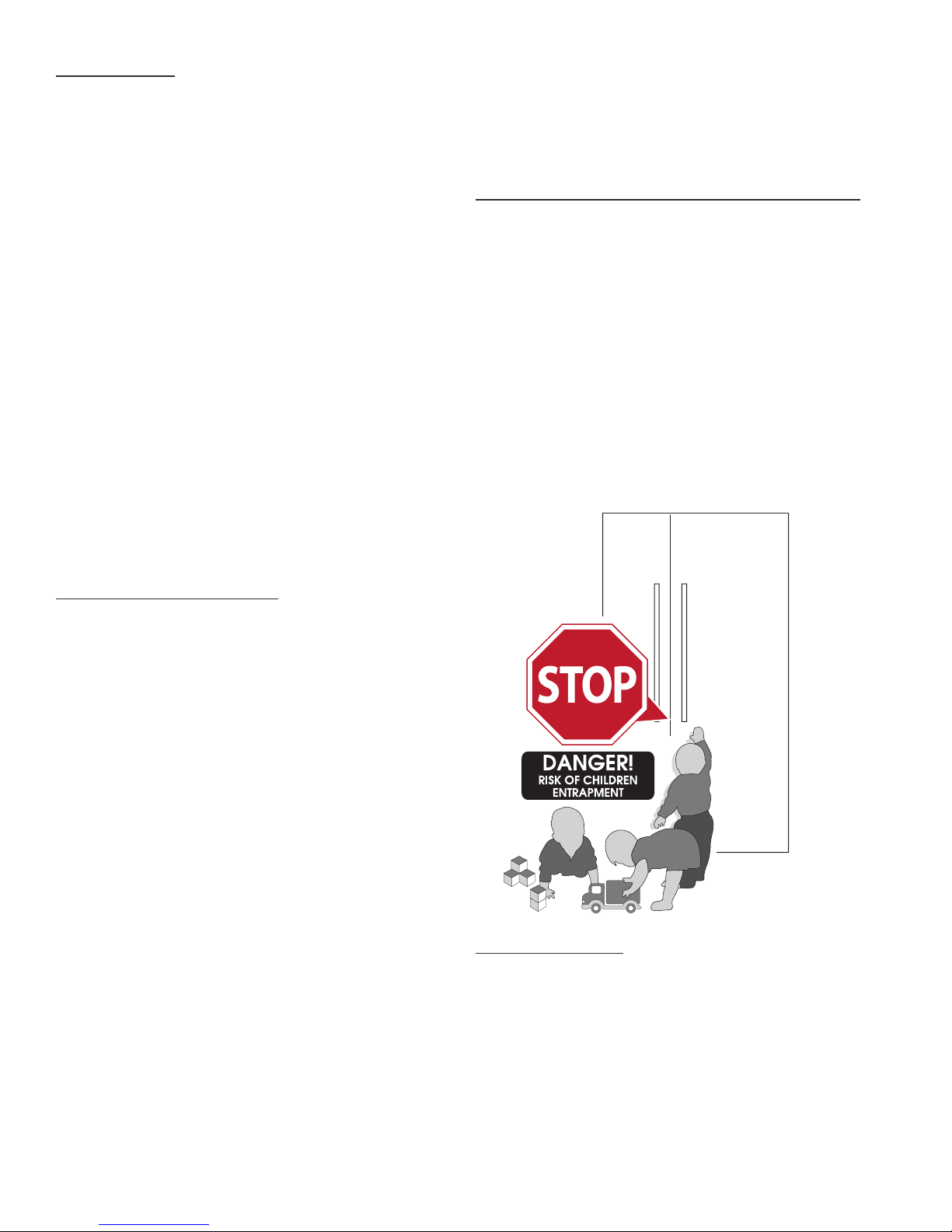
Child entrapment and suffocation are not problems
of the past. Junked or abandoned refrigerators are
still dangerous...Even if they will sit for “just a few
days”. If you are getting rid of your old refrigerator,
please follow the instructions below to help prevent
accidents.
BEFORE YOU THROW AWAY YOUR OLD
REFRIGERATOR OR FREEZER:
• Take off the doors.
• Leave the shelves in place so that children may
not easily climb inside.
SAFETY PRECAUTIONS
• This refrigerator must be properly installed and
located in accordance with the installation
instructions before it is used.
• Do not allow children to climb, stand or hang
on the shelves in the refrigerator. They could
seriously injure themselves or damage the
refrigerator.
• Do not store or use gasoline or other flammable
vapors and liquids in the vicinity of this or any
other appliance.
• Keep hands away from the “pinch point” areas
(gaps between the doors and between the doors
and cabinet). Small areas are not necessarily safe.
• Unplug the refrigerator before cleaning and
making repairs.
• Setting temperature control to OFF only removes
power from the refrigeration system, it does not
remove power from other circuits. For example,
temperature control and lights.
CFC DISPOSAL
Your old refrigerator may have a cooling system that
used CFCs (chlorofluorocarbons). CFCs are believed
to harm stratospheric ozone. If you are throwing away
your old refrigerator, make sure the CFC refrigerant
is removed for proper disposal by a qualified service.
If you intentionally release this CFC refrigerant you
can be subject to fines and imprisonment under
provisions of the environment legislation.
TRUE RESIDENTIAL
2
™
Page 7

3 - 6
s i t e p r e p a r a t i O n
e l e c t r i c a l r e q u i r e m e n t s
THE TRUE 42
3
Page 8
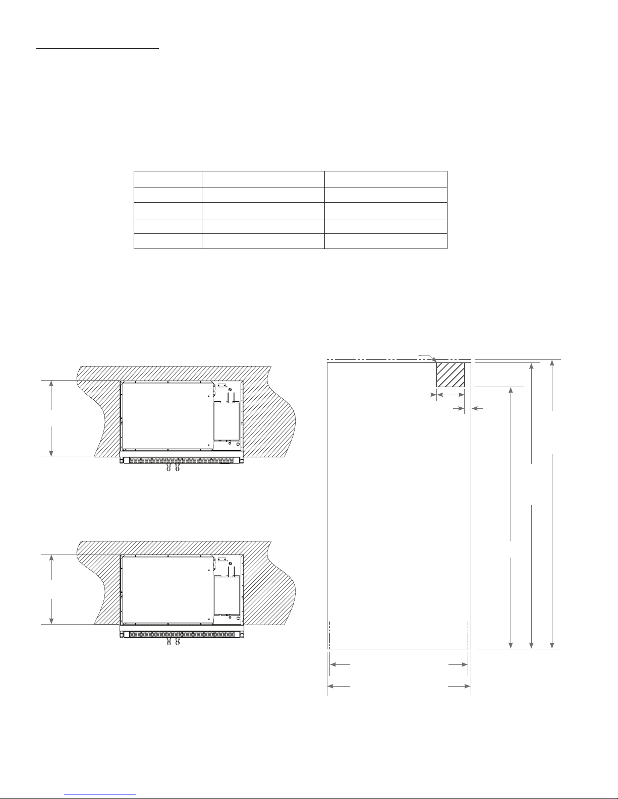
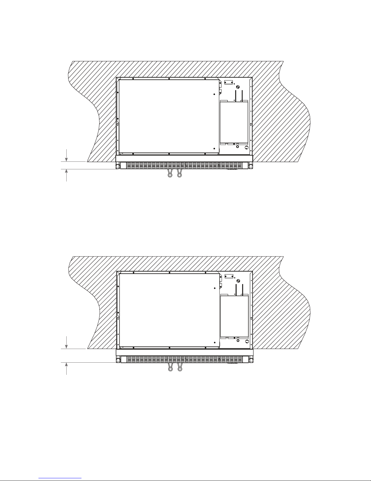
SITE PREPARATION
• Rough Opening dimensions. (See figure 1 and 2)
• For FLUSH installations the front face of the unit will be flush with the surrounding cabinets. (See figure 3)
• For PROUD (Standard) installations, the front face of the unit will extend beyond cabinets. (See figure 4)
MEASUREMENTS & WEIGHT
FLUSH PROUD
WIDTH
DEPTH 26
HEIGHT
42
84
¼
”
”
¼
”
WEIGHT* 720 Lbs 720 Lbs
Cord Length 8 feet 8 feet
* Because of the weight of this unit, it is recommended to consult a ooring
expert prior to installation. The ooring beneath the unit should be rated to
support at least 150 pounds per square foot.
TOP VIEW
FIGURE 1 - ROUGH OPENING
Electrical located in
¾
”
41
”
24
”
84
FRONT VIEW
FIGURE 2 - ROUGH OPENING
this area
" MINIMUM
26
FLUSH INSTALL
" MINIMUM
24
PROUD INSTALL
FLUSH INSTALL
PROUD INSTALL
¾
" PROUD INSTALL
41
"
8
"
2
84
¼
"
FLUSH
INSTALL
"
84
PROUD
INSTALL
"
77
NOTE: DIMENSIONS MAY VARY BY ± 1/8”
TRUE RESIDENTIAL
4
™
¼
" FLUSH INSTALL
42
Page 9
TOP VIEW
FIGURE 3 - FLUSH INSTALLATION
3/16
"
2
TOP VIEW
FIGURE 4 - PROUD INSTALLATION
3/16
"
4
NOTE: DIMENSIONS MAY VARY BY ± 1/8”
THE TRUE 42
5
Page 10
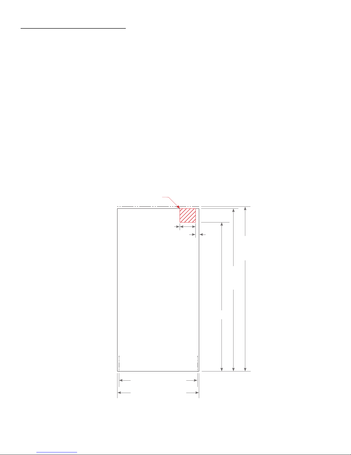
ELECTRICAL REQUIREMENTS
For all built-in models, the electrical supply should be located within the shaded area shown in the
illustration (See Figure 5). Follow the National Electrical Code and local codes and ordinances when
installing the receptacle. A separate circuit, servicing only this appliance is required. A ground fault
circuit interrupter (GFCI) is not recommended and may cause interruption of operation.
• POWER SUPPLY 115 V AC, 60 HZ
• CIRCUIT BREAKER 15 AMP
• RECEPTACLE 3-PRONG GROUNDING-TYPE
NOTES:
• THE OUTLET MUST BE CHECKED BY A QUALIFIED ELECTRICIAN TO BE
SURE THAT IT IS WIRED WITH THE CORRECT POLARITY.
• VERIFY THAT THE OUTLET IS PROPERLY GROUNDED.
FRONT VIEW
FIGURE 5 - ROUGH OPENING
Electrical located
in this area
"
8
"
2
84
¼
"
FLUSH
INSTALL
"
84
PROUD
INSTALL
"
77
NOTE: DIMENSIONS MAY VARY BY ± 1/8”
TRUE RESIDENTIAL
6
™
¾
" PROUD INSTALL
41
¼
" FLUSH INSTALL
42
Page 11

7 - 11
s p e c i f i c a t i O n s
THE TRUE 42
7
Page 12

OVERALL DIMENSIONS
TOP VIEW
9/16
"
41
CABINET WIDTH
25/32
"
23
½
"
2
DOORS OPEN 90º
20
13/16
"
5/8
"
26
DOORS OPEN 135º
1/32
"
13
TRUE RESIDENTIAL
8
™
NOTE: DIMENSIONS MAY VARY BY ± 1/8”
17
5/32
"
Page 13

83
31/32
FRONT VIEW
"
29/32
"
72
21/32
"
67
DOOR
HEIGHT
30
27
25
15/32
29/32
25/32
"
"
"
¾
"
83
CABINET
HEIGHT
NOTE: DIMENSIONS MAY VARY BY ± 1/8”
3
15/16
"
SIDE VIEW
THE TRUE 42
9
Page 14

n O t e s
TRUE RESIDENTIAL
10
™
Page 15

11 - 14
a n t i - t i p B r a c k e t i n s t a l l a t i O n
l e v e l i n g t h e u n i t
THE TRUE 42
11
Page 16

ANTI-TIP KIT INSTALLATION
ANTI-TIP BRACKET KIT:
• One (1) anti-tip bracket (Figure 1.1)
• Four (4) masonry 3/16" screws
• Eight (8) wood #12 – 2" screws
• Twelve (12) 1/4" washers
FOR ALL FULL SIZE RESIDENTIAL MODELS, THE ANTITIP BRACKET ENGAGES WITH THE REAR LEVELING
LEGS TO SECURE THE UNIT. FOLLOW THESE STEPS
TO SECURE THE BRACKET BEFORE MOVING THE
UNIT INTO FINAL OPERATING POSITION.
1. Determine final location of the unit. For a FLUSH
install, measure back 24-31/32" (Dimension A)
from the surrounding cabinetry. For a PROUD
install, measure back 22-31/32" (Dimension B)
from the surrounding cabinetry. For either type of
install, place the anti-tip bracket centered in the
rough opening.
25/32
"
20
2. Using the bracket as a guide, drill pilot holes into
the floor and wall. It is recommended to secure the
bracket to as many floor joists and wall studs as
possible.
3. Using the provided screws and washers, secure the
bracket to the wall/floor. Adjust the rear rollers to
just above their lowest position and move the unit to
its final position. Raise the rear rollers a minimum
of 1/8" to engage the bracket.
FIGURE 1.1 - ANTI-TIP BRACKET
DIMENSION A
Flush Install
31/32
"
24
NOTES:
Dimensions may vary by ± 1/8”
DIMENSION B
Proud Install
31/32
"
22
• BECAUSE OF THE WEIGHT OF THIS UNIT (720 LBS), IT IS RECOMMENDED TO CONSULT A
FLOORING EXPERT PRIOR TO INSTALLATION. THE FLOORING BENEATH THE UNIT SHOULD BE
RATED TO SUPPORT AT LEAST 150 POUNDS PER SQUARE FOOT.
• EIGHT (8) ¼-20 X 1" LAG BOLTS SECURING THE UNIT TO THE SKID DURING SHIPPING MAY
ALSO BE USED ON THE INSTALLATION OF THE ANTI-TIP BRACKET.
!
WARNING
TIP OVER HAZARD
A child or adult could tip the refrigerator resulting in property damage or bodily harm. Follow these instructions
to properly install the anti-tip device. If the unit is moved, verify the device is properly engaged before normal
usage of unit commences.
1
/8”
TRUE RESIDENTIAL
12
™
NOTE: DIMENSIONS MAY VARY BY ±
Page 17

LEVELING THE UNIT
It is very important that the refrigerator sits level. This will insure that the doors will align and seal properly
and that the drain pans will not spill over.
TO LEVEL THE UNIT:
1. PLACE A LEVEL ON THE INTERIOR FLOOR. CHECK AND ADJUST FOR LEVEL FROM FRONT
TO BACK, ALSO CHECK AND ADJUST FOR LEVEL FROM RIGHT TO LEFT.
2. ADJUST THE FRONTS USING A SET OF PLIERS OR A WRENCH. (SEE FIGURE 6)
3. ADJUST THE REAR USING A 7/16" SOCKET AND RATCHET. (SEE FIGURE 6) TURN CLOCK-
WISE TO RAISE THE REAR OF THE UNIT.
FIGURE 6 - LEG ADJUSTMENTS
REAR LEG
ADJUSTMENT
FRONT LEG
ADJUSTMENT
NOTE: DIMENSIONS MAY VARY BY ± 1/8”
THE TRUE 42
13
Page 18

n O t e s
TRUE RESIDENTIAL
14
™
Page 19

15 - 22
B a s i c e l e c t r O n i c c O n t r O l O p e r a t i O n s
THE TRUE 42
15
Page 20

BASIC ELECTRONIC CONTROL OPERATIONS
The following pages describe the basic input operations performed at the control panel;
• Switching unit ON and OFF
• Adjusting set-point (temperature adjustment)
• Enabling and disabling door ajar alarm feature
• Switching accent lighting systems ON and OFF
PLEASE NOTE THAT THOUGH POSSIBLE TO DISPLAY TEMPERATURES IN FAHRENHEIT OR
CELSIUS, IN MOST CASES FAHRENHEIT READINGS ARE SHOWN IN THIS MANUAL.
UNIT ON/OFF
All units are shipped in ON Mode. When electricity is supplied to the appliance, a short power up
diagnostics test is initiated followed by one audible beep, the lights energizing and temperature readings
appearing in the LCD.
NOTES:
• WHENEVER THE UNIT IS SWITCHED OFF USING THE POWER KEY, THE WORD “OFF”
WILL BE VISIBLE IN THE LCD (SEE FIGURE 7) AS LONG AS THERE IS ELECTRICITY
SUPPLIED TO THE APPLIANCE.
• WHENEVER THE UNIT IS SWITCHED ON USING THE POWER KEY, THE UNIT EMITS ONE
AUDIBLE BEEP, AND THEN TEMPERATURE READINGS WILL APPEAR IN THE LCD.
(SEE FIGURE 8).
• IF THE UNIT EXPERIENCES ANY PROBLEMS DURING THE POWER UP DIAGNOSTIC TEST,
THEN THE APPROPRIATE FAULT CODES WILL BE DISPLAYED.
(SEE PAGE 21, FIGURE 13 - NOTIFICATION ALERTS).
WARNING!
!
WHEN IN “OFF” MODE, AC LINE VOLTAGE IS STILL PRESENT AT MAIN CONTROL BOARD!
FIGURE 7 - CONTROL PANEL OFF
OFF
FIGURE 8 - CONTROL PANEL ON
TRUE RESIDENTIAL
16
™
-4°F
34°F
Page 21

ZONE NAVIGATION (TEMPERATURE ADJUSTMENT)
To adjust set-points, press ZONE for the appropriate compartment, then DOWN or UP key on control panel
in multiple key strokes until the desired set-point is achieved (See Figure 9). Each key stroke equals a one
degree change and is accompanied by an audible beep. When the desired set-point is reached press the
ZONE key until you reach the “HOME” screen, where the current zone temperatures will be displayed.
NOTES:
• THE TEMPERATURE RANGE IN A FREEZER ZONE IS -4°F (-20°C) TO +4°F (-16°C).
• THE TEMPERATURE RANGE IN A REFRIGERATOR ZONE IS +34°F (+1°C) TO +42°F (+6°C).
• INITIAL FACTORY SET-POINTS ARE 0°F (-18°C) IN A FREEZER ZONE AND 38°F (3°C) IN A
REFRIGERATOR ZONE.
• THE INITIAL STROKE OF THE UP OR DOWN KEY WILL CHANGE THE PREVIOUS SET-POINT BY
ONE DEGREE.
FIGURE 9 - ADJUSTING SET-POINTS
ZONE
NAVIGATION
NOTIFICATION
(SEE NOTIFICATION ALERTS)
AREA
ZONE
-4°F
REFRIGERATOR
34°F
34°F
ZONE
ZONE
FREEZER
-4°F
THE TRUE 42
17
Page 22

MODE NAVIGATION
The following pages illustrate unique customer input operations performed at the control panel. The input
operations described are:
TEMPERATURE UNIT SELECTION MODE, VACATION MODE, AND HOLIDAY MODE.
(SEE FIGURE 10).
NOTES: (HOLIDAY MODE)
• SET-POINTS CANNOT BE CHANGED AND MANUAL DEFROST CANNOT BE INITIATED.
• THE FOLLOWING HOLDS TRUE IN ACCORDANCE WITH STAR-K REQUIREMENTS:
- Freezer defrosting functions will convert to a fixed time base sequence.
- The compartment/zone thermistors will still detect cut-in and cut-out, which is the determining factor to
start/stop the cooling process, but there will be a random sixteen (16) to twenty-one (21) second delay
before cooling begins/ends.
- The phrase “HOLIDAY MODE ACTIVE” in the LCD remains energized when the door is closed.
FIGURE 10 - MODE NAVIGATION
MODE
NAVIGATION
-4°F
MODE
Activate Holiday Mode
Te mperatureºf
Vacation Mode
Activate Holiday Mode
Te mperature ºf
Vacation Mode
34°F
MODE
MODE
Holiday Mode Active
press any key to
exit
Te mperature Is
Celcius
press any key to exit
Te mperature Is
Fahrenheit
press any key to exit
Activate Holiday Mode
Te mperatureºf
Vacation Mode
TRUE RESIDENTIAL
18
™
MODE
Vacation Mode
Active
press any key to exit
Page 23

ACCENT LIGHTING SYSTEM
All models are equipped with an accent lighting system in the refrigerator and or freezer compartment(s). To
energize the accent lighting system, press the LIGHT key, and navigate to the corresponding compartment,
DOOR or ON will appear in the LCD indicating the accent lights are enabled (See Figure 11). With the accent
lighting system ON, the LED’s will be energized and stay illuminated when the door is closed, in the DOOR
position the lighting system will only be energized with the door opening.
NOTE:
• WHEN LIGHTS ARE PLACED IN “ON” MODE, LIGHTS WILL NOT FADE-UP WHEN DOOR OPENS.
FIGURE 11 - ACCENT LIGHTS ON/DOOR
LIGHT
LIGHT
BACK TO HOME SCREEN
REFRIGERATOR LIGHT DOOR
FREEZER LIGHT DOOR
Exit
NAVIGATION
-4°F
34°F
LIGHT
REFRIGERATOR LIGHT ON
FREEZER LIGHT DOOR
Exit
REFRIGERATOR LIGHT DOOR
FREEZER LIGHT DOOR
Exit
FREEZER LIGHT DOOR
REFRIGERATOR LIGHT DOOR
Exit
LIGHT
REFRIGERATOR LIGHT DOOR
FREEZER LIGHT ON
Exit
THE TRUE 42
19
Page 24

ALARM NAVIGATION (DOOR AJAR ALARM FEATURE ON/OFF)
All Residential Series units are equipped with a door ajar alarm feature. To enable the door ajar alarm, press
the ALARM key on the control panel and “DOOR AJAR ALARM ON” will appear in the LCD indicating the alarm
is enabled (See Figure 12). With the alarm enabled, the notification icons will appear and an audible alarm will
beep continuously whenever a door is left open for more than 5 minutes. To disable the door ajar alarm, press
the ALARM key again and “DOOR AJAR ALARM OFF” will appear in the LCD.
FIGURE 12 - ALARM NAVIGATION
AL ARM
BACK TO MAIN SCREEN
NAVIGATION
-4°F
refrigerator
door ajar
freezer
drawer ajar
Door Alarm On
Exit
34°F
ALARM
Door Alarm Off
Exit
TRUE RESIDENTIAL
20
™
ALARM
Door Alarm Off
exit
ALARM
TO STOP ALARM BUZZER PRESS
Page 25

NOTIFICATION ALERTS
NOTIFICATION ALERTS
MAIN SCREEN C
C
The diagrams on these pages illustrate what a customer may see in the LCD if the appliance needs attention
(See Figure 13).
FIGURE 13 - NOTIFICATION ALERTS
service
required
freezer
door ajar
refrigerator
door ajar
refrigerator
high temp
freezer
high temp
-4°F
34°F
showroom
mode
OULD SHOW THE FOLLOWING
OMMUNICATION ERROR:
Communication Error
call for service
THE TRUE 42
21
Page 26

n O t e s
TRUE RESIDENTIAL
22
™
Page 27

23 - 26
s h e l v i n g
r e m O v i n g t h e D O O r s
k i c k p l a t e i n s t a l l a t i O n
THE TRUE 42
23
Page 28

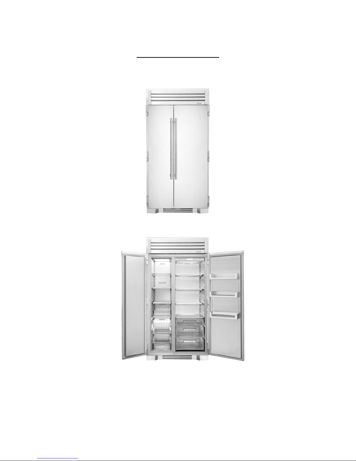
SHELVING
All shelving and door bins come
packaged inside the unit.
(See Figure 14)
FIGURE 14
REFRIGERATOR STORAGE
GL ASS SHELVES
Remove the top foam piece holding the glass shelves. Carefully remove shelves and set aside. (See Figure 15).
Remove all other packing material. To install, insert glass shelf into the shelf standards on the back wall, with
the front tilted upward, and then lower the front until it stops. (See Figure 16). To remove or adjust a glass
shelf, tilt up, and then lift up and out.
FIGURE 15 FIGURE 16
Final Glass Shelf Installation
DOOR BINS
The door bins are located in the bottom drawer of the refrigerator. (See Figure 17). To install, push tabs into the
slots in the door and slide downward unit it stops. (See Figure 18). To remove or adjust a door bin, lift up and
away from door back.
NOTE: BE CAUTIOUS OF PLACING TALL ITEMS IN TOP DOOR BIN, AS ITEMS MIGHT INTERFERE
WITH UI CONTROL PANEL.
FIGURE 17 FIGURE 18 Final Door Bin Installation
TRUE RESIDENTIAL
24
™
Page 29

DRAWERS
To remove a drawer, pull drawer forward until it stops. Use a Phillips screw driver to remove the two (2) screws
securing the drawer to the slides, then lift the drawer up and out of unit. (See Figure 19). To reinstall, pull drawer
slides all the way forward on unit, and then slide the drawer onto the slides until the hook on the back of the
slide is over top of the drawer, reinstall the screws using the Phillips screw driver.
Figure 19
FREEZER STORAGE
WIRE SHELVES
Remove the top foam piece holding the wire shelves. Carefully remove shelves and set aside. (See Figure 20).
Remove all other packing material. To install, insert wire shelf into the shelf standards on the back wall, with the
front tilted upward, and then lower the front until it stops. (See Figure 21). To remove or adjust a wire shelf, tilt
up, and then lift up and out.
FIGURE 20 FIGURE 21 Final Wire Shelf Installation
WIRE BASKETS
To remove a basket, pull drawer forward until it stops. Use a Phillips
screw driver to remove the two (2) screws securing the basket to the
slides, then lift the basket up and out of unit. To reinstall, pull drawer
slides all the way forward on unit, and then slide the basket onto the
slides until the hook on the back of the slide is over top of the rails,
reinstall the screws using the Phillips screw driver. (See Figure 22).
Figure 22
THE TRUE 42
25
Page 30

REMOVING THE DOORS
REMOVING THE DOORS
Open the door to 90 degrees. (See Image 23). Lift the door straight up and out of the hinges. (See Image 24).
To re-install, hold the door 90 degrees to the opening and align hinge posts to the hinges. Lower the door into
place.
FIGURE 23 FIGURE 24
KICK PLATE INSTALLATION
KICK PLATE
The kick plate is shipped with the unit but not attached to allow access to level the unit (See Image 25). Once
the unit is level, the kick plate attaches to the front, bottom of the unit with magnets located on the left and
right. (See Image 26).
FIGURE 25 FIGURE 26 - Magnets Installed Kick Plate
TRUE RESIDENTIAL
26
™
Page 31

27-28
g e n e r a l m a i n t e n a n c e
r e p l a c e m e n t p a r t s
THE TRUE 42
27
Page 32

GENERAL MAINTENANCE
Keeping the condenser coil clean will minimize required service and lower electrical cost. The condenser coil is
accessible from the front. (See Figure 27).
The condenser coil should be cleaned by removing dust and other build-up from the tube assembly with
vacuum or a cleaning rag.
When properly cleaned you should be able to see through the tube assembly.
Warranty does not cover cleaning the condenser coil.
FIGURE 27
REPLACEMENT PARTS
True maintains a record of the cabinet serial number for your unit. If at any time during the life of your unit a
part is needed, you may obtain that part by furnishing the model number and serial number to the company
from whom you purchased the cooler. For replacement parts contact the dealer from whom you purchased the
refrigerator or call True parts department at 1-800-424-TRUE. Inquires can be sent to the following address:
ATTENTION PARTS DEPARTMENT
TRUE MANUFACTURING
2001 EAST TERRA LANE
O’FALLON, MO 63366-4434
TRUE RESIDENTIAL
28
™
Page 33

Page 34

CONTACT US
www.true-residential.com
(6 36) 240 -2400 • toll free (8 88) 616-878 3
RD 5/1/15 20
 Loading...