

Page 1
USER MANUAL - ELECTRONIC DEADBOLT WITH REMOTE
08102017
Page 2

Index
OPERATION INSTRUCTIONS
Exterior Assembly Overview.......................................................................Page 9
Locking and Unlocking / Changing Programming Code /
Adding User Codes......................................................................................Page 10
Deleting User Codes / Automatic Lock Function /
Temporarily Disable Auto Lock...................................................................Page 11
Remote Control Set-Up and Operation......................................................Page 12
Vacation Mode / Sound On and Off / Secure Lock-out Period................Page 13
Restore Factory Settings / Low Battery Warning /
Consumer Friendly Message Guide...........................................................Page 14
Installation Trouble Shooting...............................................................Page 15
Consumer Assistance.................................................................................Page 16
Template.......................................................................................................Page 17-18
Programming Record..................................................................................Page 19-20
Limited Warranty.................................................................................Page 21
INSTALLATION INSTRUCTIONS
Package Contents / Tools Required......................................................... Page 1
Prepare Door and Jamb..............................................................................Page 2
Adjusting Deadbolt Latch Set.....................................................................Page 3
Installing Deadbolt Latch Set.....................................................................Page 4
Preparing Interior Assembly.......................................................................Page 5
Installing Exterior Assembly.......................................................................Page 6
Installing Interior Assembly........................................................................Page 7-8
For troubleshooting tips and “how to videos” visit www.truboltlocks.info
Page 3
Page 1
B. A.
C. D.
INSTALLATION INSTRUCTIONS
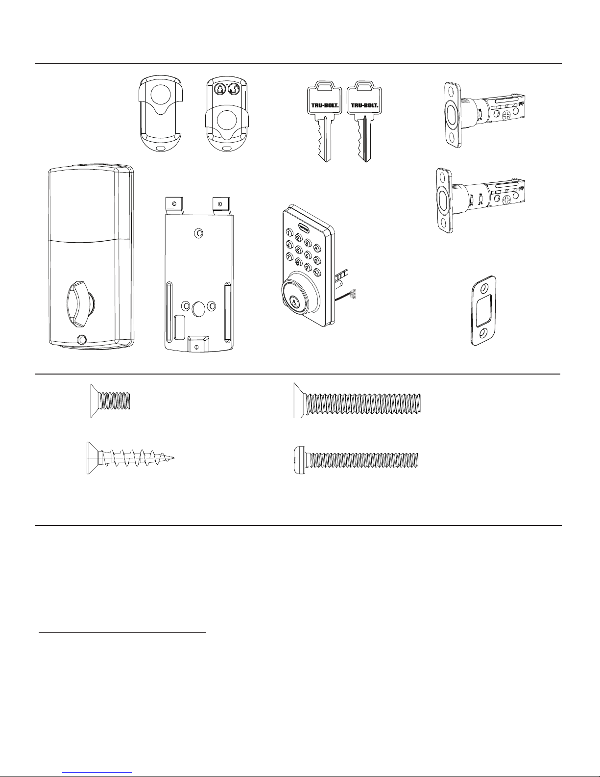
Package Contents
Tools Required
Tools Required for Installation
on Pre-drilled Doors:
• Phillips Head Screwdriver
NOTE: DO NOT USE a drill.
Tools Required for Installation
on Doors That Require Drilling:
• Drill
• Tape Measure
• Pencil
• 2-1/8” (54mm) Drill Hole Saw
• 1” (25mm) Drill Bit
• 1/16” (2mm) Drill Bit
• Chisel
• Hammer
• Phillips Head Screwdriver
Deadbolt Strike Plate
Deadbolt Latch Set (Adjustable)
2-3/8” (60mm) to 2-3/4” (70mm)
Interior Assembly
Mounting Plate
Exterior Assembly
Entry keys (2 ea.)
Wireless Remote (1 ea.)
5/16” (8mm) Screws - 2 ea. 7/8” (22mm) Screws - 2 ea.
3/4” (19mm) Screws - 5 ea. 1” (25mm) Screw - 1 ea.
Electronic lock requires (4) High Quality
AA Alkaline batteries. When all 4 batteries
are installed in the correct position, hear 2
beeps and the keypad will illuminate blue.
DO NOT TOUCH the keypad until the keypad
stops illuminating.
Batteries (not included)
Page 4
Page 2
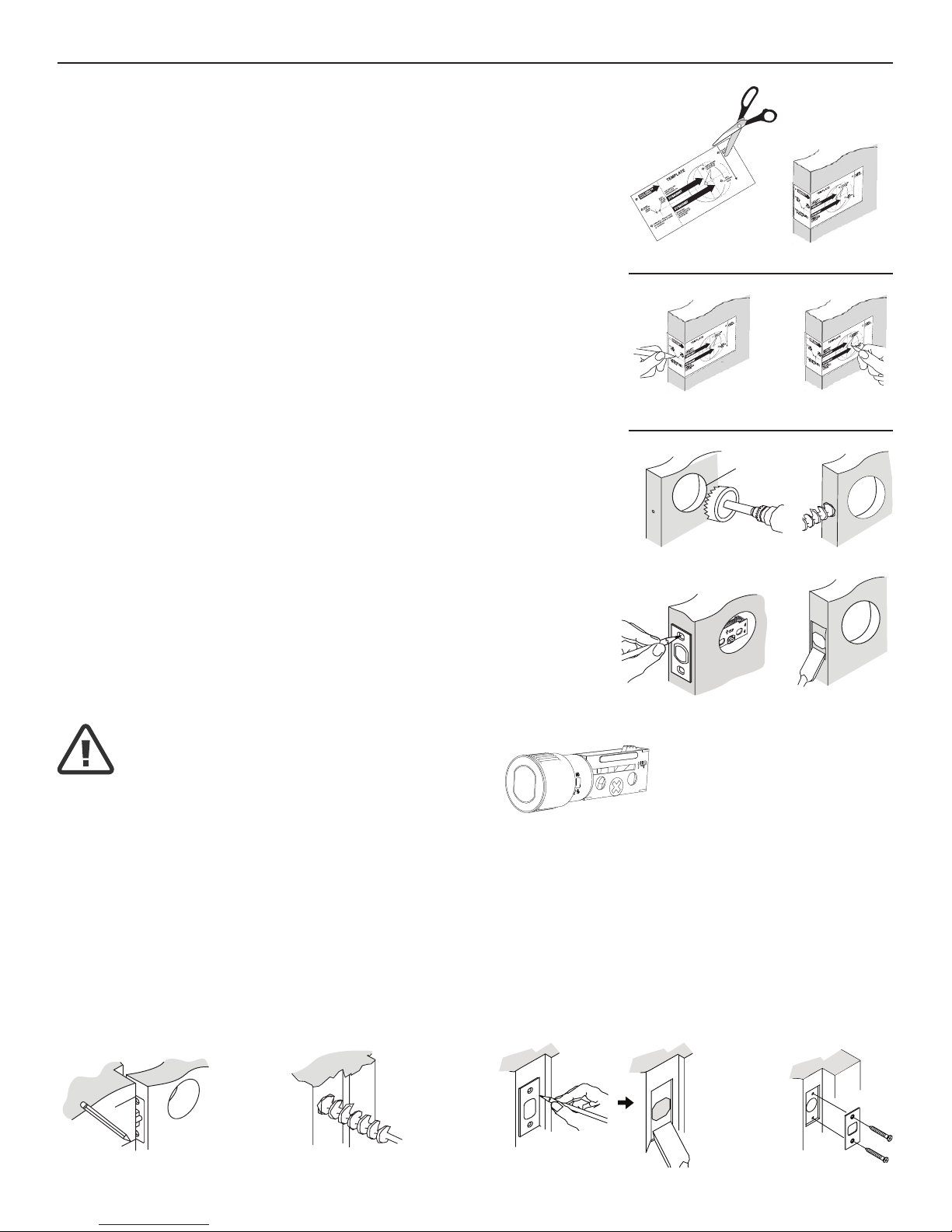
NOTE: For installation on doors with pre-drilled holes skip to page 4.
1. TEMPLATE
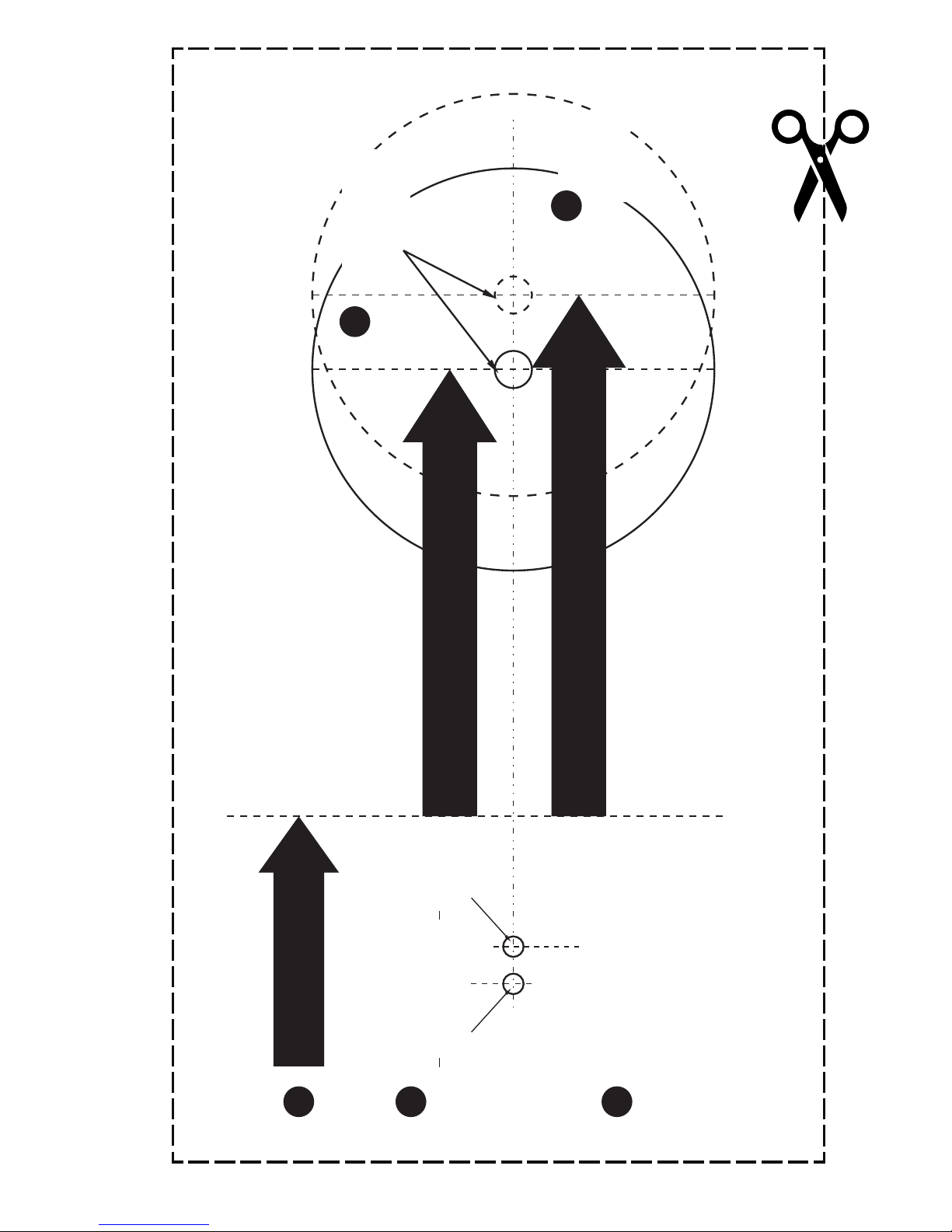
a. Cut out template printed on page 17 & 18 of this Manual
(Figure 1a).
b. Fold template and place on door 36” (915mm) from
the ground as marked (Figure 1b).
2. MARK THE DOOR FOR DRILLING
b. Mark center hole on door edge through guide on
template for 1” (25mm) latch bolt (Figure 2a).
a. Mark center hole on door face through guide on
template for 2-3/8” (60mm) or 2-3/4” (70mm)
backset (Figure 2b).
3. DRILL AND CHISEL DOOR
a. Drill 2-1/8” (54mm) hole through door face as marked
for lock set (Figure 3a).
b. Drill 1” (25mm) hole in center of door edge for
Deadbolt Latch Assembly (Figure 3b).
c. Insert Deadbolt Latch Assembly in hole keeping it
parallel to face of door. Mark outline and remove latch
(Figure 3c).
d. Chisel 1/8” (3mm) deep or until latch face is ush
with door edge (Figure 3d).
4. MARK AND DRILL DOOR JAMB
a. Mark center hole on edge of jamb even with the center of the Latch Bolt on door
edge. (Figure 4a).
b. Drill 1” (25mm) hole 1-3/16” (30mm) deep in door jamb on center mark (Figure 4b).
c. Outline outside edges of Strike Plate (Figure 4c).
d. Chisel 1/8” (3mm) deep for Strike Plate or until ush (Figure 4d).
e. Install Strike Plate using two 3/4” (19mm) screws provided (Figure 4e).
PREPARE DOOR AND JAMB
Figure 4a Figure 4b
Figure 4e
Figure 4c Figure 4d
NOTE: For Drive in Latch, drill hole size indicated on template and
press until it is ush with door edge.
U
P
Figure 1a
Figure 2a Figure 2b
Figure 3a
Figure 3c
Figure 1b
Figure 3b
Figure 3d
2-1/8” (54mm)
Page 5
Page 3
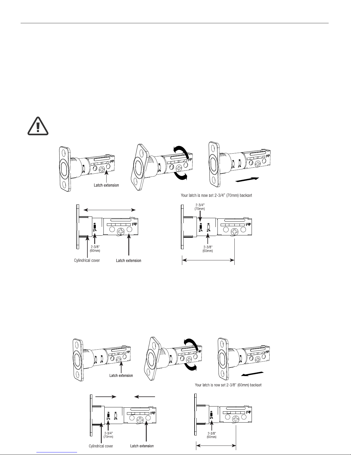
ADJUSTING DEADBOLT LATCH SET
NOTE: Deadbolt Latch Set is shipped with the backset set at 2-3/8” (60mm)
Measure the backset (backset is distance between edge of the door and the center of Lock).
1. TO CONVERT FROM 2-3/8” (60mm) BACKSET TO 2-3/4” (70mm) BACKSET
a. Hold latch with numbers facing forward and thumb pressing on the bolt (Figure 1a).
b. Rotate the cylinder cover clockwise (Figure 1b).
c. Pull and twist the extension plate all the way out (Figure 1c).
d. Rotate the cylinder cover counter clockwise so that the marking aligns with
the 2-3/4” (70mm) position indicator (Figure 1d).
2. TO CONVERT FROM 2-3/4” (70mm) BACKSET TO 2-3/8” (60mm) BACKSET
a. Hold latch with numbers facing forward and thumb pressing on the bolt (Figure 2a).
b. Rotate the cylinder cover clockwise (Figure 2b).
c. Push and twist the extension plate all the way in (Figure 2c).
d. Rotate the cylinder cover counter clockwise so that the marking aligns with
the 2-3/8” (60mm) position indicator (Figure 2d).
Figure 1a Figure 1b Figure 1c
Figure 1d
Must lock in place.
Figure 2a Figure 2b Figure 2c
Figure 2d
NOTE: Do not extend Cylindrical Cover past 2-3/4” (70mm)
or it will break once extended
Page 6
Page 4
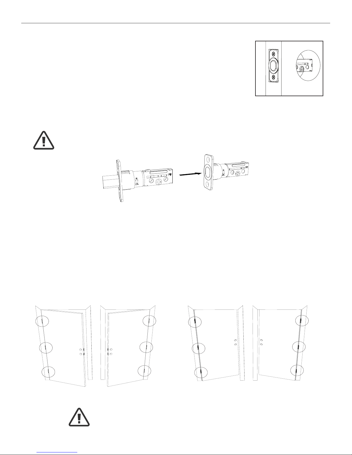
3. INSTALLING THE DEADBOLT LATCH SET (need Phillips head screwdriver)
a. Insert Deadbolt Latch Set into door edge hole with the word
“UP” and the arrow on the extension plate facing UP. Cross
shaped spindle connector will be at the bottom of the Deadbolt
Latch Set (Figure 3a).
b. Make sure the face plate sits ush with the door. Do not force
the latch into the mortise ush. Chisel out excess material if
necessary for a ush t.
c. Using two 3/4” (19mm). screws provided, screw the latch into the
door with a hand held screwdriver. DO NOT OVER TIGHTEN.
4. IDENTIFYING YOUR DOOR HANDING
Stand outside the door.
a. If the hinges are on the left your door is Left Handed (Figure 4a and 4b).
b. If the hinges are on the right your door is Right Handed (Figure 4a and 4b).
INSTALLING DEADBOLT LATCH SET
Figure 4a
OUT SWING DOOR
Left Handed Door
Hinges are on the left side
Right Handed Door
Hinges are on the right side
IN SWING DOOR
Left Handed Door
Hinges are on the left side
Right Handed Door
Hinges are on the right side
Figure 4b
Figure 3a
Deadbolt Latch Extended Deadbolt Latch Retracted
NOTE: Deadbolt Latch must be retracted when installing
NOTE: You are standing outside the door
Page 7
Page 5
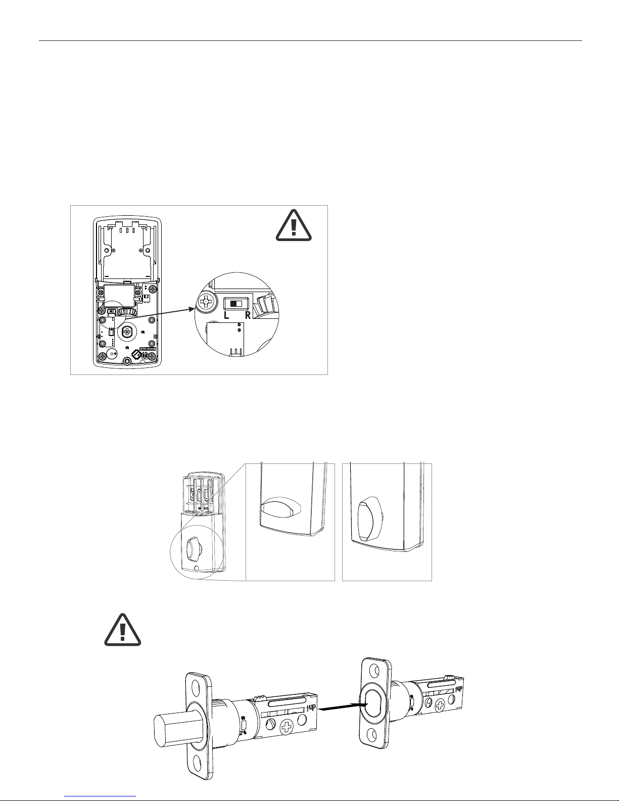
PREPARING THE INTERIOR ASSEMBLY
6. SET THE ENTRY SWITCH FOR LEFT OR RIGHT HANDED DOOR
a. Gently move the switch to “L” for Left Handed Door (Figure 6a).
b. Gently move the Switch to “R” for Right Handed Door (Figure 6b).
7. SET THE INTERIOR KNOB POSITION FOR LEFT OR RIGHT HAND HINGED DOORS
a. The Interior Knob goes in the Horizontal position for Left Handed Doors (Figure 7a).
b. The Interior Knob goes in the Vertical position for Right Handed Doors (Figure 7b).
Entry Switch (Left or Right)
Figure 6a-b
NOTE: Make sure deadbolt Latch is retracted
5. UNPACK THE INTERIOR ASSEMBLY
a. Remove the battery cover by sliding the cover upward.
b. Locate the screw holding the Mounting Plate to the Interior Assembly. Remove the
screw to release the Mounting Plate from the Interior Assembly.
Right Handed Door
(Vertical)
Left Handed Door
(Horizontal)
Figure 7a Figure 7b
Page 8
Page 6
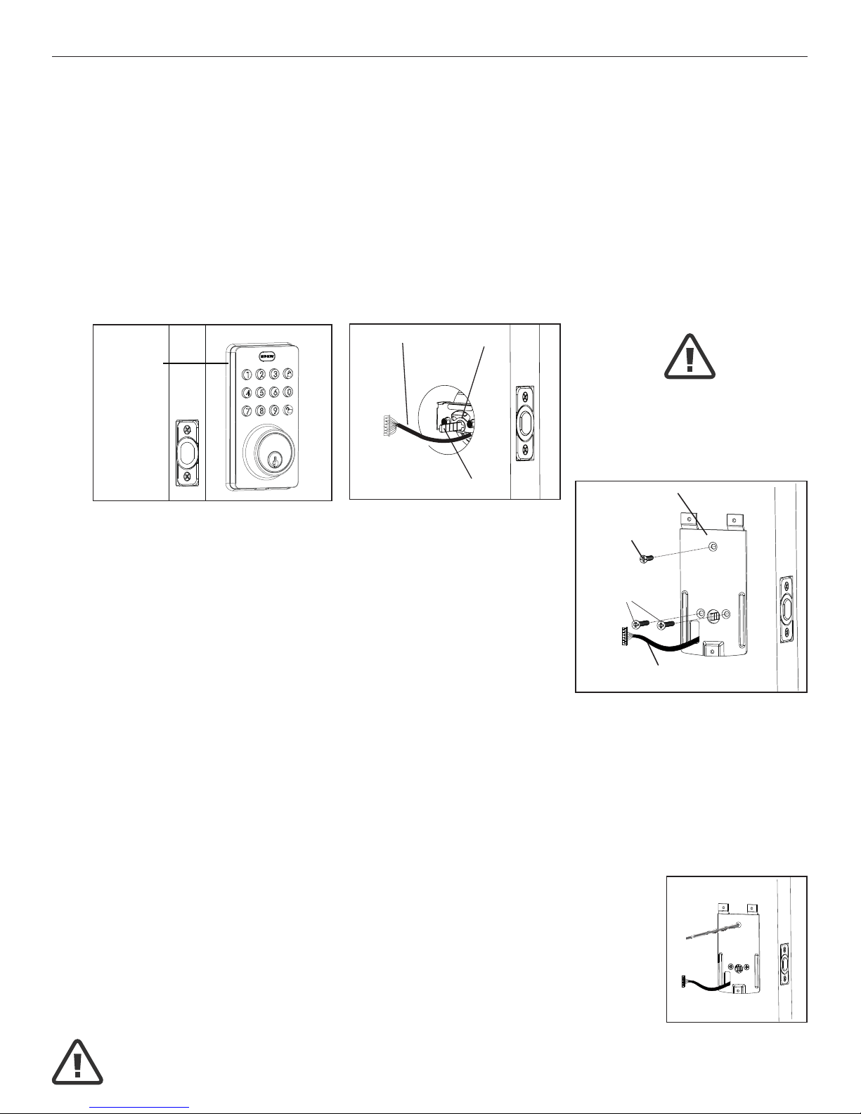
9. SECURING THE EXTERIOR ASSEMBLY TO THE DOOR
a. From the side marked “This side against
door”, route the Control Wire through the
rectangular slot in the Mounting Plate (Figure 9a).
b. Place Mounting Plate against door with tailpiece passing
through the center hole in the three hole set (Figure 9b).
c. Secure the Mounting Plate to the Exterior Assembly using
two 7/8” (22mm) Screws(B) (Figure 9c).
d. Hand tighten with a Phillips Screwdriver leaving loosely connected (Figure 9d).
e. Check that the Rubber Gasket is properly aligned and correct as necessary
(Figure 8a).
f. Check vertical alignment of the lock (Figure 9f).
g. Tighten securely with a hand held Phillips Screwdriver. DO NOT OVER TIGHTEN
10. OPTIONAL INSTALLATION
a. Using a 1/16” (2mm) drill bit, drill a pilot hole in your door using the
Mounting Plate upper hole as a guide (Figure 10a).
b. Insert one 3/4” (19mm) screw(C) and tighten.
8. INSTALLING THE EXTERIOR ASSEMBLY
Work with the Door Open for easy access.
a. Unpack the Exterior Assembly. Use care to not scratch the green circuit board
during handling and installation.
b. Check that the Rubber Gasket is properly seated on the Exterior Assembly
(Figure 8a).
c. Insert the Exterior Assembly onto the door with the tailpiece going through the
Deadbolt Latch Set cross shaped spindle connector in the VERTICAL POSITION.
Route the Control Wire through the door under the Deadbolt Latch Set (Figure 8c).
INSTALLING EXTERIOR ASSEMBLY
Right handed door view
Rubber
Gasket
Control
Wire
Mounting Plate
3/4” (19mm) screw
(Optional installation)
7/8” (22mm) screws
Control Wire
C
B
Tailpiece
(Vertical)
Latch
Hole
Figure 8a Figure 8c
Figure 10a
Figure 9a-f
NOTE: Lock and unlock using the key to see if
the Deadbolt Latch is opening and closing easily.
NOTE: Tailpiece must be
positioned vertically
Page 9
Page 7
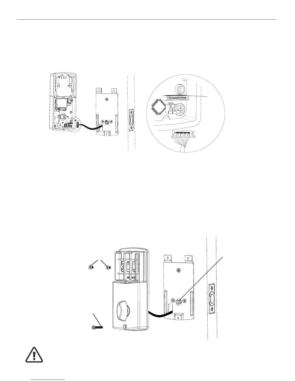
INSTALLING INTERIOR ASSEMBLY
11. ATTACH THE CONTROL WIRE TO THE INTERIOR ASSEMBLY
a. Use care to attach the Control Wire male plug to the Interior Assembly female
socket connector.
b. Carefully insert the male plug, smooth side up, into the female socket on the
interior assembly. DO NOT FORCE! (Figure 11a).
12. ATTACH THE INTERIOR ASSEMBLY TO DOOR
a. IMPORTANT: Make sure the knob is in the vertical position for right hand door and
horizontal position for left hand door.
b. Make sure the tailpiece (Figure 12a) is in the vertical position.
c. Position the Interior Assembly over the vertically positioned tailpiece and carefully
push the Interior Assembly against the door (Figure 12a).
d. Using two 5/16” (8mm) screws(A) and one 1” (25mm) screw(D), attach the
Interior Assembly to the Mounting Plate. DO NOT OVER TIGHTEN SCREWS
Vertical Tailpiece
NOTE: Lock and unlock using Interior Knob to see if the
latch is opening and closing easily.
Figure 12a
Match color
Figure 11a
5/16” (8mm) screws
1” (25mm) screw
A
D
Page 10
Page 8
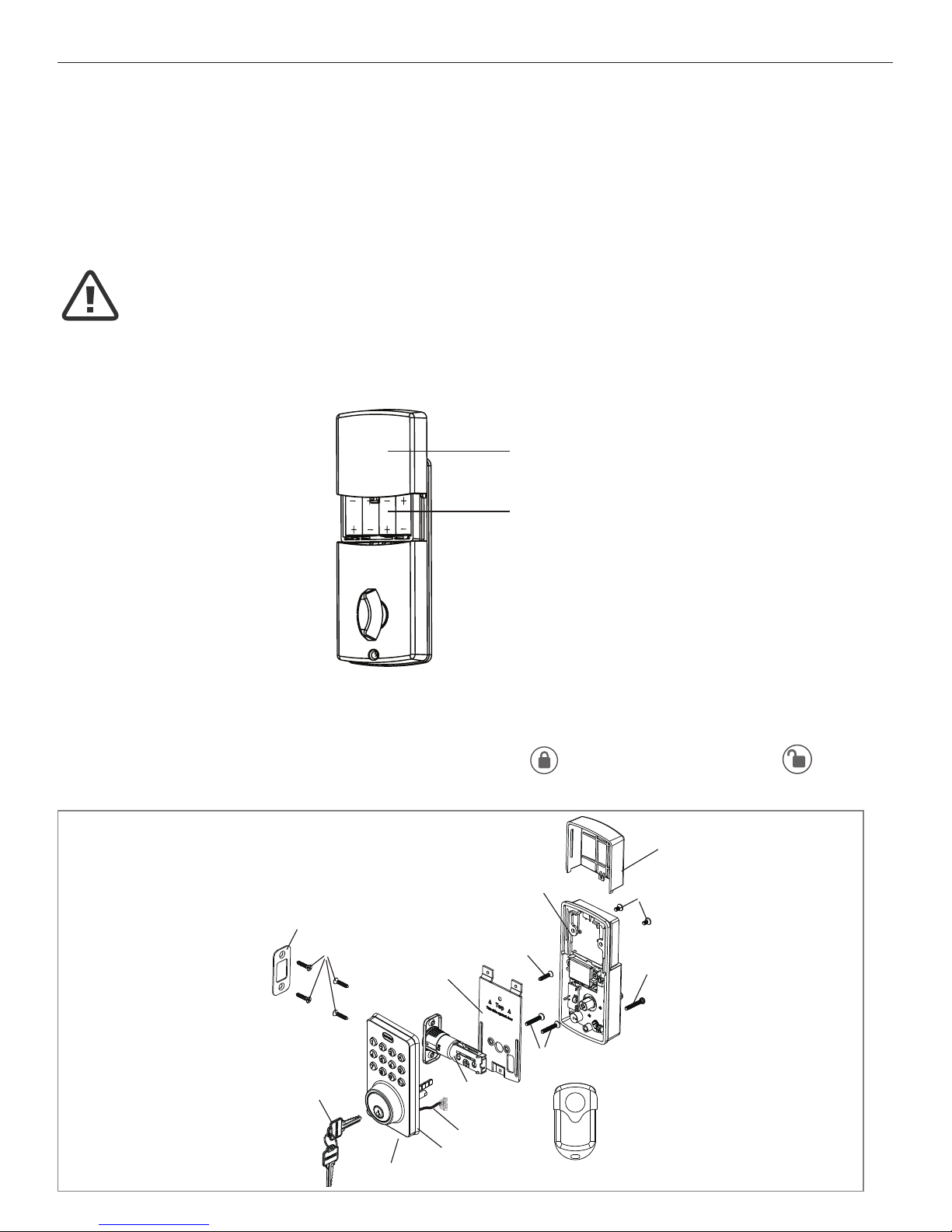
13. Installing Batteries
a. Slide battery cover up and remove.
b. Insert 4 AA high quality Alkaline batteries into the Battery Compartment in the
direction noted +/- on the Compartment. The Lock will beep 2 times, the keypad
will illuminate blue, and the Tru-Bolt button will ash green twice to signify that
it has received power (Figure 13a).
c. Replace battery cover and slide down on to the Interior Assembly to cover the
batteries (Figure 13b).
14. Testing Lock
a. Always test with the Door Open and in unlocked position.
b. Test the Lock using the Interior Knob. The bolt should move smoothly in and out.
c. Test the Lock using the Keypad. To lock press
and then press “1234”
to unlock.
INSTALLING INTERIOR ASSEMBLY (CONT.)
Battery
Cover
4 AA
Batteries
NOTE: Do not touch the Keypad until the blue light turns off.
Do not use rechargeable batteries or non-alkaline batteries.
Figure 13a-b
INSTALLATION OVERVIEW
Strike Plate
3/4” (19mm) screws(C)
Mounting Plate
Interior Assembly
Optional
3/4”(19mm) Screw(C)
7/8”(22mm) screws(B)
Latch
Exterior Assembly
Control Wire
Rubber Gasket
Key
Remote
Battery Cover
5/16”(8mm)
screws(A)
1”(25mm)
Screw(D)
Page 11
Page 9
OPERATION INSTRUCTIONS
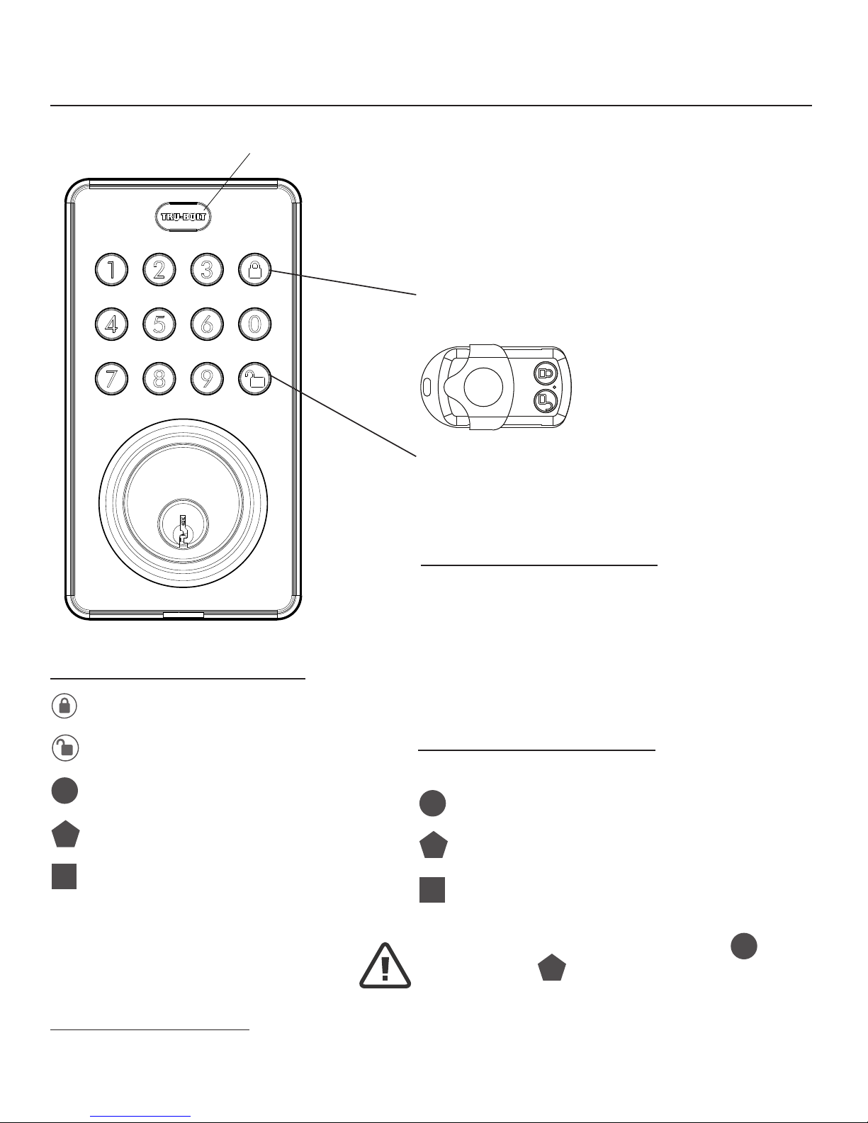
Exterior Assembly Overview
Light indicator
Green Light Indicator
• Indicates Successful Programming Step
• Indicates Unlocking is Successful
Red Light Indicator
• Indicates Failed Programming Step or Installation
• Indicates Locking is Successful
Electronic lock requires (4) High Quality
AA Alkaline batteries. When all 4 batteries
are installed in the correct position, hear 2
beeps and the keypad will illuminate blue.
DO NOT TOUCH the keypad until the keypad
stops illuminating.
5 Seconds - Complete all the programming steps in the programming mode within 5 seconds.
Lock - Used to lock door
Lock button
Unlock - Used to unlock door / Programming
Programming - Used in programming steps
Unlock button
Factory Settings
The lock comes factory preset with a:
Programming code - 123456
User code - 1234
User ID - 01
ID
PC
UC
Batteries (not included)
Programming Symbols
Lock
Unlock / Programming
Programming Code (6 digits)
User Code (4-8 digits)
User ID (01-50, 2 digits)
ID
PC
UC
Programming Tips
Please change the Programming Code
PC
and
the User Code
UC
as soon as possible after
installation to insure security.
Page 12
Page 10
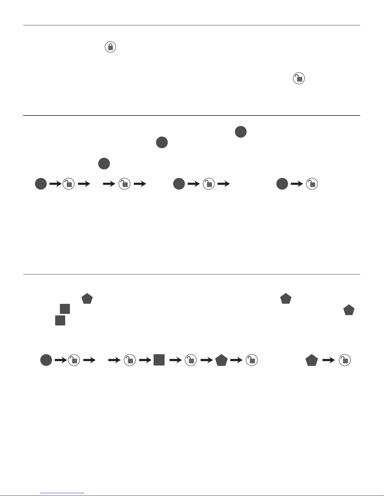
TO LOCK THE LOCK
Using Keypad: Press
and then hear 2 beeps and lights red.
TO UNLOCK THE LOCK
Using Keypad: Enter a valid User Code (default code is 1234) and press and hear
1 beep and lights green.
CHANGE CURRENT OR PRESET PROGRAMING CODE
PC
Factory default Programming Code
PC
= 123456, this is the master password for your lock.
All programming functions require this code. Follow the below sequence to change the
Programming Code
PC
to your custom 6 digit combination.
TO ADD A NEW USER CODE (you can add up to 50 new user codes)
The User Code
UC
must be a 4-8 digit combination. Each User Code
UC
is then linked to
a User ID
ID
(which is any number between 01-50) to identify an individual User Code UC.
(User ID
ID
1-9 should be entered as 01-09 so they are 2 digits).
Hear 1 beep and Light Indicator illuminates green.
Record New and Changed Codes on Programming Record located on Page 19 & 20.
NOTE: When a NEW PROGRAMMING CODE is set, the default factory code (123456) is
deleted for safety.
Hear 1 beep and Light Indicator illuminates green.
NOTE: When a NEW USER CODE is set, the default factory code (1234) is deleted
for safety.
Record New and Changed Codes on Programming Record located on Page 19 & 20.
123456, or new
Programming code
6 digits 6 digits
For example: to add the User ID - 08 to User Code - 5678, enter the following:
4 new Re-enter
Changing Programming Code
Adding User Codes
Locking and Unlocking
PC PCPC
1 Re-enter
ID
UC UC
PC
5678
5678
08
Page 13
Page 11
Set Auto Lock:
Hear 1 beep and Light Indicator illuminates green.
20 - 900 seconds
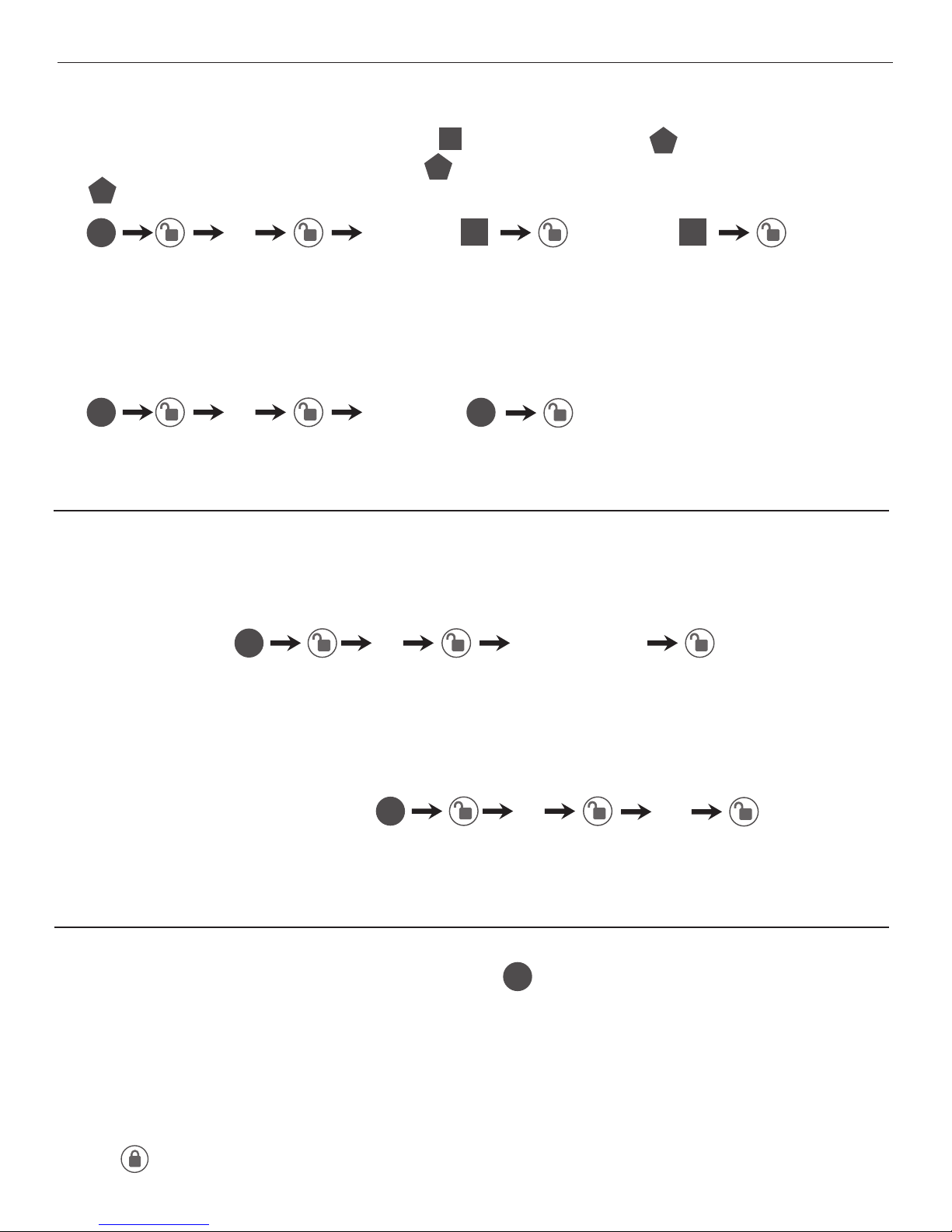
DELETE ONE EXISTING OR PRESET USER CODE
The unit comes with a factory User ID ID= 01 for User Code
UC
= 1234.
IMPORTANT: To delete 1 User Code
UC
, the lock must have more than 1 User Code
UC
in its database.
SET OR CANCEL AUTO LOCK
You can set the lock to automatically close after each time the lock is opened. Time
value range = 20 - 900 seconds, enter the following:
DELETE ALL USER CODES
IMPORTANT: this will delete the user codes but not the programming code, enter
the following.
Hear 1 beep and Light Indicator illuminates green.
To cancel Auto Lock set the time to 00, enter the following:
Cancel Time Value Auto Lock:
Hear 1 beep and Light Indicator illuminates green.
Hear 1 beep and Light Indicator illuminates green.
2 Existing re-enter
5 Time Value
5 00
3 re-enter
Automatic Lock Function
Deleting User Codes
PC
PC
PC
PC PC
ID ID
DISABLE:
While in Auto-Lock mode, unlock door using PC, within 10 seconds you must turn the
locking knob by hand to the locked position, wait more than 2 seconds then turn the
locking knob back to the unlock position. The Auto-Lock mode is now disabled.
RESTORE:
To restore the Auto-Lock funtion, turn the locking knob by hand to the locked position,
wait more than 2 seconds and turn the locking knob to the unlocked position or press
the
Lock button on the keypad.
Temporarily Disable Auto-Lock
Page 14
Page 12
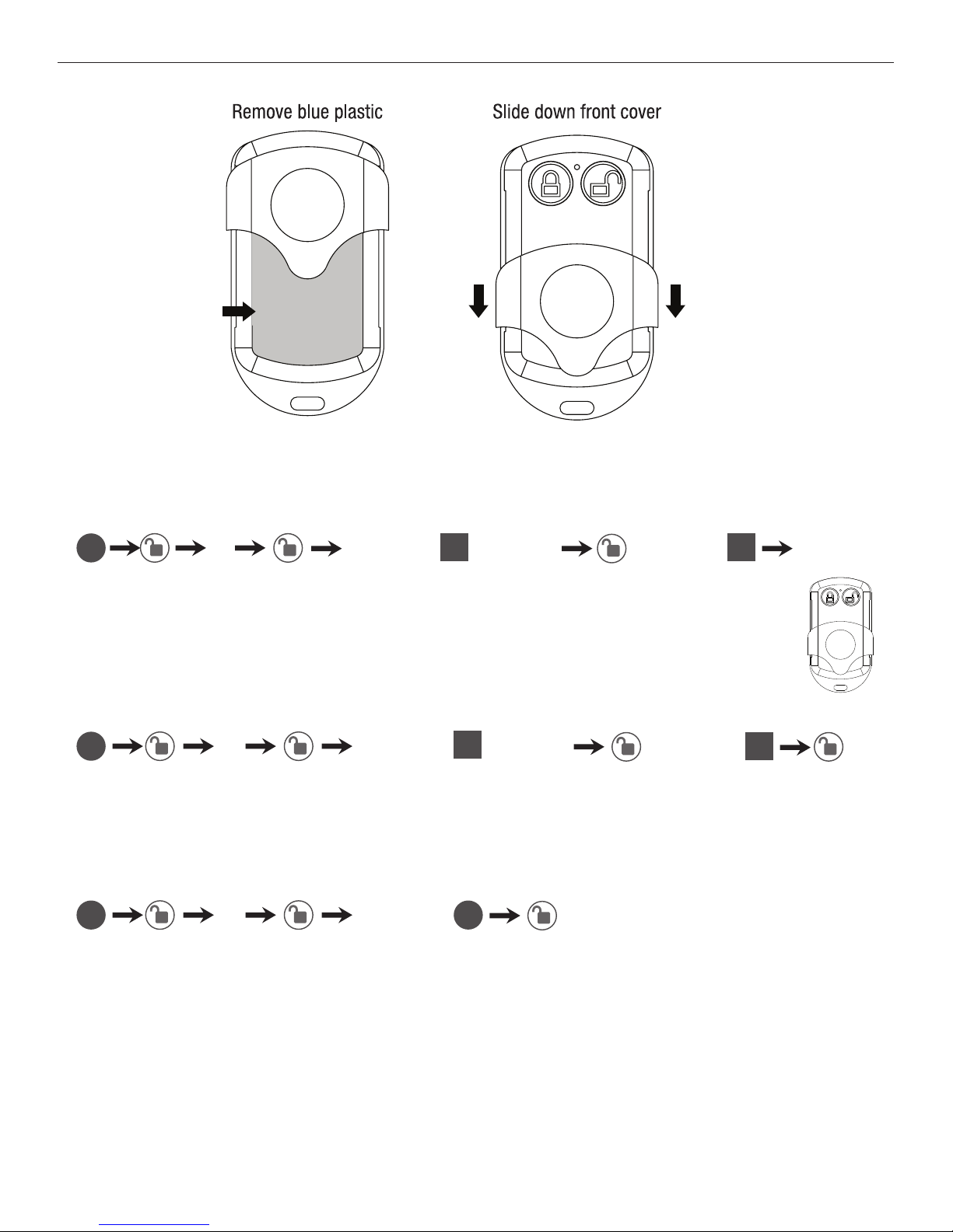
Remote Control Set-Up and Operation
ADD ONE REMOTE CONTROL (You can add up to 20 remotes, ID from 01-20)
DELETE ONE EXISTING REMOTE CONTROL
DELETE ALL REMOTE CONTROLS
Hear 1 beep and Light Indicator illuminates green.
Note: This is the only step you need to use the remote for programming.
Hear 1 beep and Light Indicator illuminates green.
Note: You must have more than 1 remote synced to this lock to DELETE ONE OR ALL REMOTES
Hear 1 beep and Light Indicator illuminates green.
7 Existing (01-20) re-enter
8 Existing (01-20) re-enter
9 re-enter
PC
PC
PC PC
ID
ID
ID
ID
Press any
button on
the remote
Page 15
Page 13
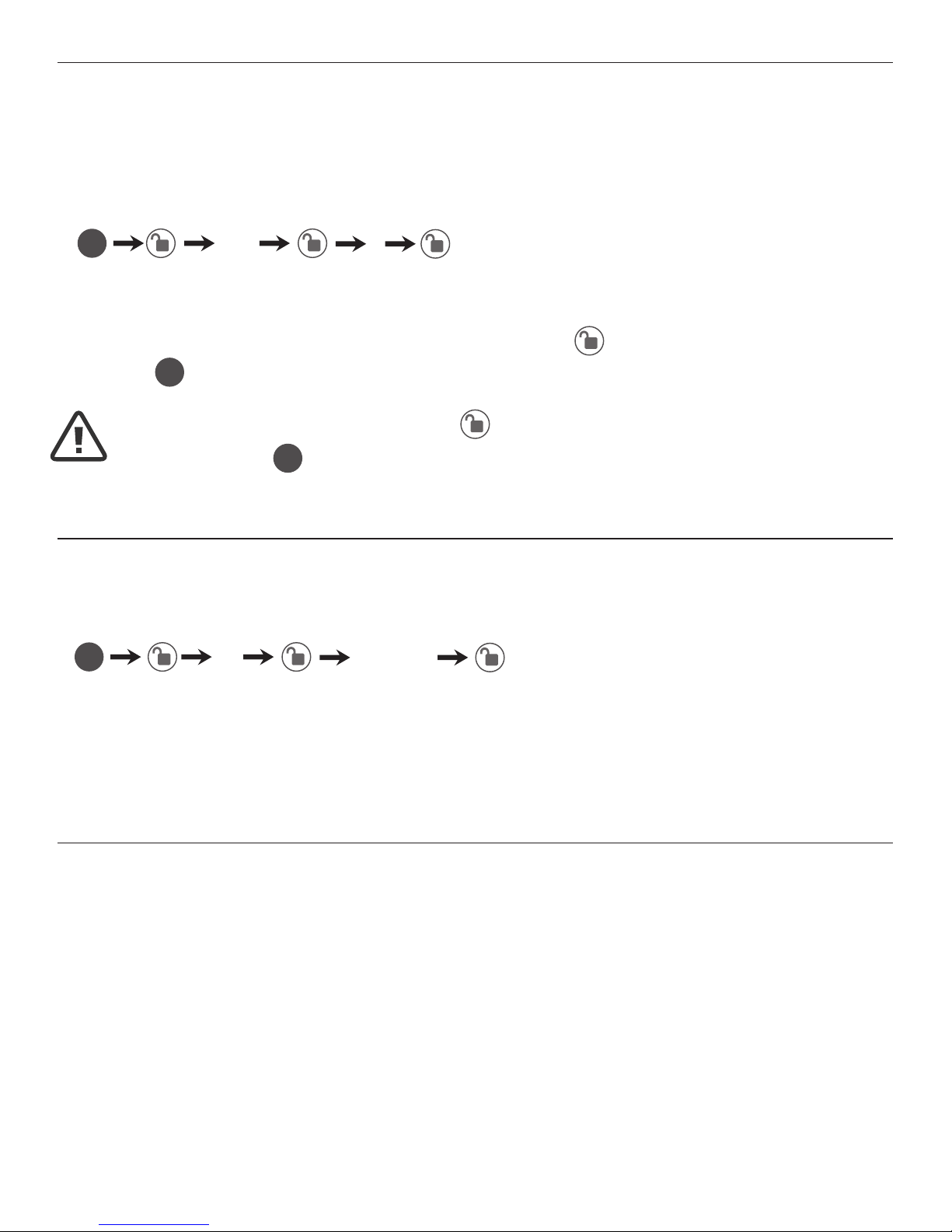
With Vacation Mode enabled, the system enters into low-power comsumption mode.
During this mode, all buttons and functions including the remote control will be invalid
until they are re-enabled (see steps below).
ENABLE:
DISABLE:
To disable the Vacation Mode, you must press and hold for more than 3 seconds,
then input
PC
to unlock the door. Vacation Mode is now disabled.
Vacation Mode
Hear 1 beep and Light Indicator illuminates green then lock door
10 1
PC
NOTE: If you only press the for more than 3 seconds but
do not input
PC
, the system will remain in Vacation Mode.
You can “mute” or turn the “sound on” on your lock by entering the following.
(Factory setting is sound on).
Sound Off (1) - Light Indicator illuminates green.
Sound On (2) - Hear 1 beep and Light Indicator illuminates green.
6 1 or 2
Sound On and Off
PC
1 = Sound Off
2 = Sound On
Warning sounds and LED ashes red after 4 incorrect code attempts: Keypad shuts
down for 30 seconds.
Secure Lock-out Period
Page 16
Page 14
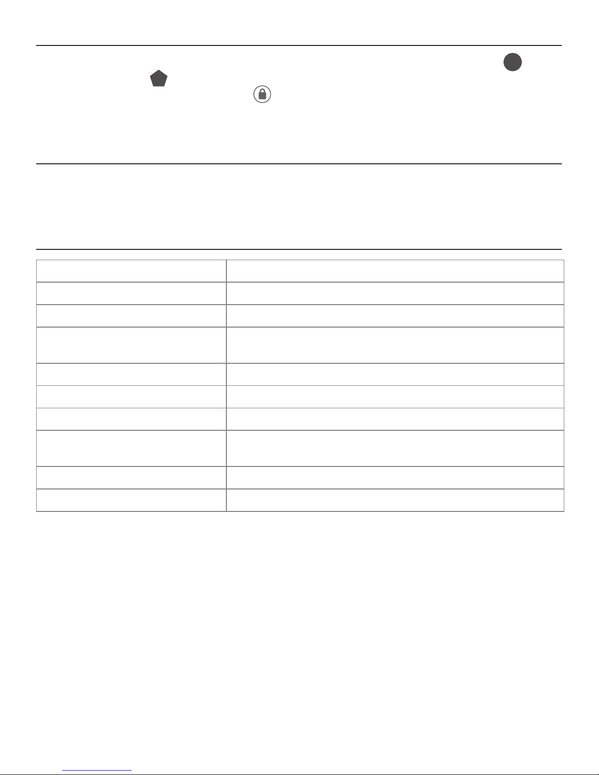
NOTE: When battery is under low voltage, the lock will give the (Low Battery Warning: Beeps and
LED ashes red for 5 seconds). During this time your lock can still work. However once the voltage
is lower than 4.3V (called Super-Low Voltage), the operation of the locking and unlocking will not
work, user must replace batteries immediately.
Consumer Friendly Message Guide
Unlock / Valid programming 1 long beep and LED illuminates green
Lock 2 short beeps and LED illuminates red - check
Invalid Programming 2 short beeps and LED ashes red twice - start over
Low Voltage Beeps for 5 seconds (7/9 times depends on operation is
unlock/lock) - change battery
Super Low Voltage 4 short beeps and LED ashes red four times - change battery
4 Incorrect code entry attempts 2 short beeps and LED illuminates red each attempt
Power on 1 long beep and 1 short beep and LED illuminates green
Chip Reset 1 long beep and 1 short beep and LED illuminates green
(may occur several times or once in a while)
Lock Error 3 long beeps LED ashes red three times
Repeat operation after Lock Error 2 short beeps three times LED ashes red six times - New
To reset the lock to the original factory settings including the Programming Code
PC
and all User Codes
UC
remove one battery for 10 seconds. Reinsert the battery and
wait for a long and short beep. Press
3 times within 3 seconds. The lock will beep
and the light indicator will turn green. If it turns red redo the operation.
Beeps and LED ashes red for 5 seconds. Replace with good quality alkaline batteries.
Note: Removing batteries does not erase active Programming or User Codes.
Restore Factory Settings
Low Battery Warning
Page 17
Page 15
INSTALLATION TROUBLE SHOOTING
Issue Solution
Latch Working
BackwardsLock unlocks when
lock button is pushed
or locks when unlock
button or code is
pushed.
Direction switch is set to incorrect setting.
Remove the Interior Assembly and move the switch to the opposite
direction.
• Check that your switch is set in the correct position Left or Right
Handed door.
If Correct
• Rotate Interior Knob and reinstall Interior
Assembly. Retest again while holding Interior Assembly in place.
Interior Knob will not
turn.
Knob or vertical tailpiece is installed in incorrect position. Remove
Interior Assembly and reposition the Interior Knob. With the Deadbolt
Latch retracted verify that the tailpiece is vertical or if extended to
2 3/8” to 2 3/4” check position the cross and that latch is not locked.
Lock will not function
electronically.
• Check that all batteries are fresh high quality
Alkaline Batteries.
• Check for proper polarity (+ -) of all batteries.
• Check that the Control Wire is attached to the Interior Assembly.
Lock gives error
signal when opening or
locking and Deadbolt
Latch will not extend
or retract completely
when door is closed.
Unlock door using Key or Interior Knob. While door is open, check
that the Deadbolt Latch
operates smoothly. Check for proper alignment of the strike plate,
adjust as needed to assure there is no binding against the Deadbolt
Latch.
Deadbolt Latch is
sticking.
Installation screws of the lock may be too tight and have to be
loosened.
• Remove Interior Assembly.
• Slightly loosen the Mounting Plate screws.
• Lock and unlock using the Key.
• Reattach Control Wire and Interior Assembly.
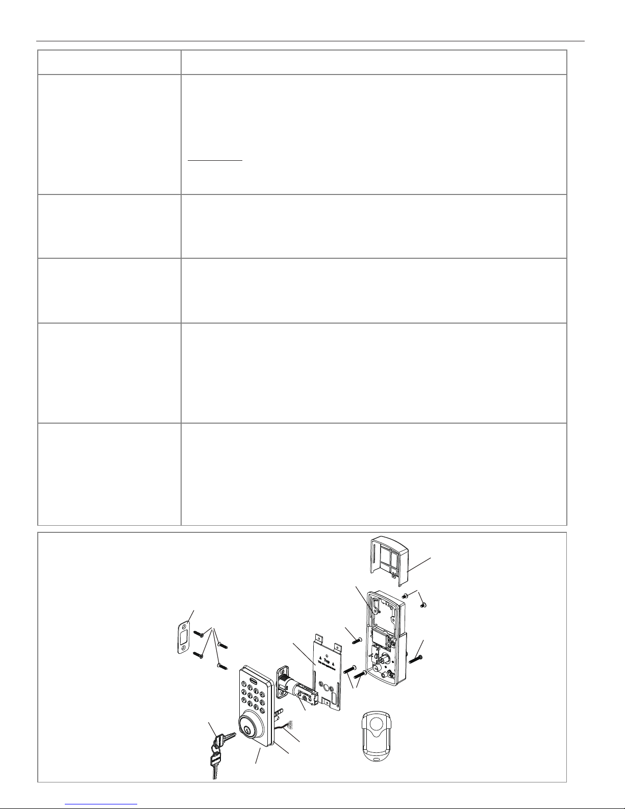
INSTALLATION OVERVIEW
Strike Plate
3/4” (19mm) screws(C)
Mounting Plate
Interior Assembly
Optional
3/4”(19mm) Screw(C)
7/8”(22mm) screws(B)
Latch
Exterior Assembly
Control Wire
Rubber Gasket
Key
Remote
Battery Cover
5/16”(8mm)
screws(A)
1”(25mm)
Screw(D)
Page 18

Page 16
EMAIL: [email protected]
WEBSITE: www.truboltlocks.info
ADDRESS: Consumer Assistance Dept.
Lewis Hyman, Inc., 860 East Sandhill Avenue Carson, CA 90746 USA
TELEPHONE: US/Canada 800-860-1677 Ext. 1801(Toll Free)
CALL CENTER HOURS: US/Canada 7am – 5pm (Pacic**) Mon – Fri
(Subject to change)
CALL BACK HOURS: Other Countries 7am – 5pm (Pacic**) Mon – Fri
(Subject to change)
Pacic**- Local time in Los Angeles, CA, USA
** Local Time based on Los Angeles California USA
CONSUMER ASSISTANCE
Page 19
Page 17
FOR INSTALLING
ENTRY LOCK AND DEADBOLTS
IMPORTANT!
PLACE TEMPLATE
ON HIGH EDGE OF
DOOR BEVEL
THEN DRILL 1"(25mm) HOLE
IN CENTER OF DOOR EDGE
(2" IN DEPTH)
FOLD HERE ON
DOOR EDGE
2 /
8
"BACKSET
3
MARK
FOR
1 "(45mm)
DOOR
3
4
DRILL
2-1/8"(54mm)
HOLE
MARK CENTER
OF HOLE ON
DOOR FACE
TEMPLATE
2 /
4
"BACKSET
3
3
8
MARK
FOR
1 "(35mm)
DOOR
Page 20

Page 18
Back of Template
Page 21

Page 19
PROGRAMMING RECORD
My Codes: Date Created
Programming Code (6 digits) / /
User Code 01 (4-8 digits) / /
User Code 02 (4-8 digits) / /
User Code 03 (4-8 digits) / /
User Code 04 (4-8 digits) / /
User Code 05 (4-8 digits) / /
User Code 06 (4-8 digits) / /
User Code 07 (4-8 digits) / /
User Code 08 (4-8 digits) / /
User Code 09 (4-8 digits) / /
User Code 10 (4-8 digits) / /
User Code 11 (4-8 digits) / /
User Code 12 (4-8 digits) / /
User Code 13 (4-8 digits) / /
User Code 14 (4-8 digits) / /
User Code 15 (4-8 digits) / /
User Code 16 (4-8 digits) / /
User Code 17 (4-8 digits) / /
User Code 18 (4-8 digits) / /
User Code 19 (4-8 digits) / /
User Code 20 (4-8 digits) / /
User Code 21 (4-8 digits) / /
User Code 22 (4-8 digits) / /
User Code 23 (4-8 digits) / /
User Code 24 (4-8 digits) / /
User Code 25 (4-8 digits) / /
Page 22

Page 20
PROGRAMMING RECORD
My Codes: Date Created
User Code 26 (4-8 digits) / /
User Code 27 (4-8 digits) / /
User Code 28 (4-8 digits) / /
User Code 29 (4-8 digits) / /
User Code 30 (4-8 digits) / /
User Code 31 (4-8 digits) / /
User Code 32 (4-8 digits) / /
User Code 33 (4-8 digits) / /
User Code 34 (4-8 digits) / /
User Code 35 (4-8 digits) / /
User Code 36 (4-8 digits) / /
User Code 37 (4-8 digits) / /
User Code 38 (4-8 digits) / /
User Code 39 (4-8 digits) / /
User Code 40 (4-8 digits) / /
User Code 41 (4-8 digits) / /
User Code 42 (4-8 digits) / /
User Code 43 (4-8 digits) / /
User Code 44 (4-8 digits) / /
User Code 45 (4-8 digits) / /
User Code 46 (4-8 digits) / /
User Code 47 (4-8 digits) / /
User Code 48 (4-8 digits) / /
User Code 49 (4-8 digits) / /
User Code 50 (4-8 digits) / /
Page 23

Page 21
Limited 1-Year Electronic Warranty
Limited Lifetime Mechanical and Finish Warranty
This Tru-Bolt® product comes with a 1-Year Limited Warranty on Electronic
Parts and a Limited Lifetime Mechanical and Finish Warranty against defects
in materials and workmanship under normal use to the original residential
user. Proof of purchase and ownership is required for the warranty to be in
effect. This warranty is non transferable and applies to the original purchaser
only, as long as the original purchaser occupies the resi
dential premises upon
which the product[s] was originally installed. This warranty DOES NOT
COVER removal and reinstallation of product[s], scratches, abrasions,
deterioration due to the use of paints, solvents or other chemicals, abuse,
misuse, or product[s] used in commercial applications, does not cover any
losses, injuries to persons/property or costs, and shipping and freight
expenses required to return product[s]. In no event shall Tru-Bolt® be liable
for any special, incidental or consequential damages. If
this product[s] is
considered a consumer product, please be advised that some local and state
laws do not allow limitations on incidental or consequential damages or how
long an implied warranty lasts, so that the above limitations may not fully
apply. Refer to your local laws for your specic rights under this warranty. If
there are any problems please call our customer service with any questions or
concerns.
Package Warranty:
Limited Lifetime Mechanical & Finish Warranty:
This Tru-Bolt® product[s] comes with a 1-
Year Limited Warranty on
Electronic Parts and a Limited Lifetime Mechanical and Finish Warranty
against defects in materials and workmanship under normal use to the
original residential user. If there are any problems please call our customer
service with any questions or concerns.
See installation instructions for full
terms and conditions.
For questions / comments, technical assistance or repair parts – please call toll
free at: 1-800-860-1677 x 1801 (M-F 7am-5pm PST)
DO NOT RETURN TO STORE
Don’t forget to register your lock atTruboltlocks.info for updates.
 Loading...