

Page 1
User Manual
TRU-S500DSP
Mono Channel DSP Amplifier
Description
Thank you for purchasing TRU-S500DSP by
TruAudio. The 500 watt DSP amplifier has some
of the most advanced DSP functions available.
We have included DSP settings for all of our
passive subwoofers to get the highest performance out of each subwoofer.
Caution:
MAKE SURE TO READ THIS INSTRUCTION
MANUAL BEFORE TURNING THE POWER ON
OR HOOKING UP THIS POWER AMPLIFIER.
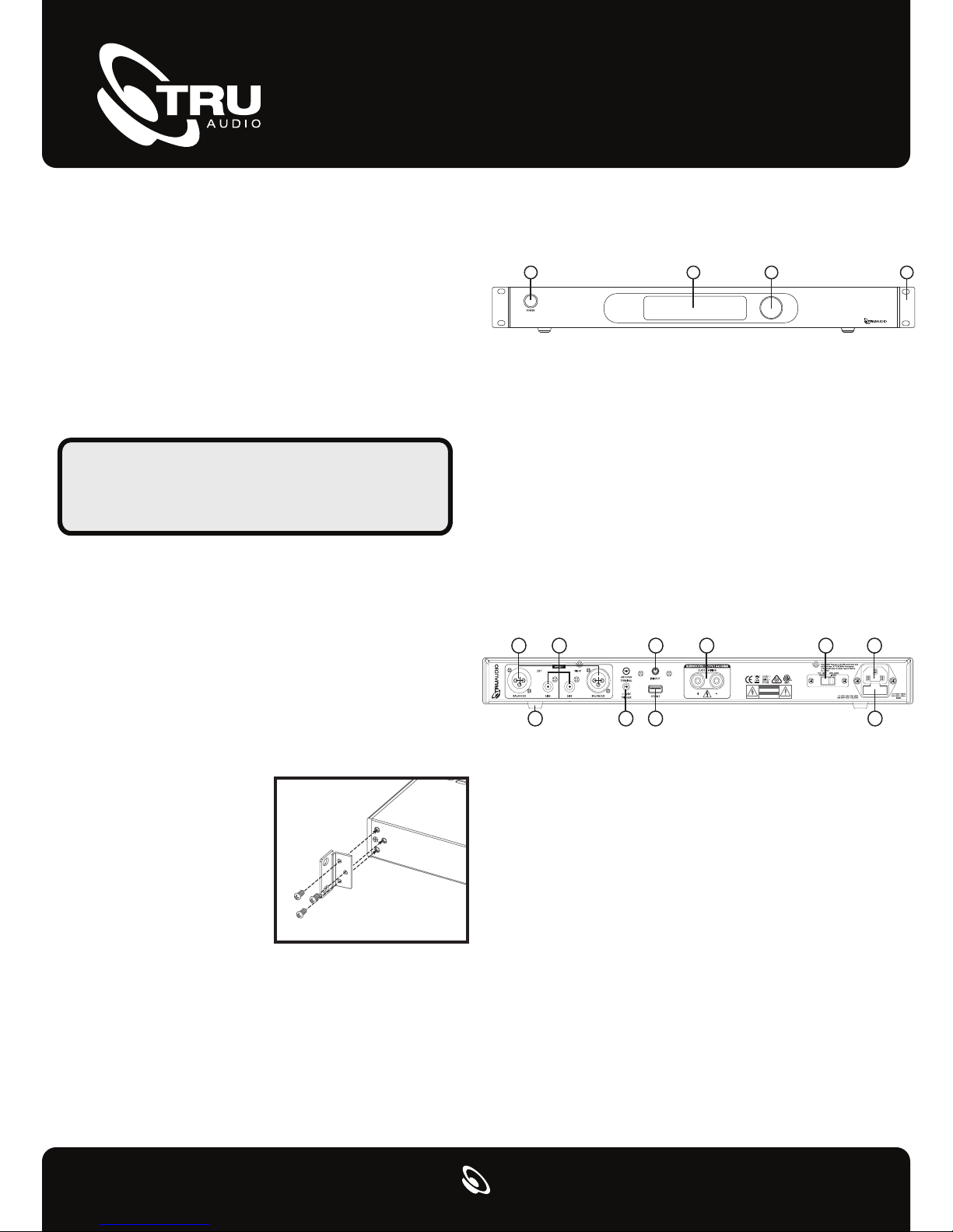
Installing Rack Mount Ears
If you are planning on installing this amplifier into a rack,
continue reading how to install the supplied rack ears.
1. Use the supplied three screws to attach the supplied
rack ears to the TRU-S500DSP amp. If required, the feet
on the bottom of the amplifier can also be removed at
this time by unscrewing the mounting screws located in
the center of each foot.
2. Due to the weight of the amplifier, it is recommended
that rear supports be
secured to the rear rack
rails. Hardware to do this
is not supplied with the
amplifier and is specific to
the type and depth of rack
being used.
TRU-S500DSP Amplifier Controls and Setup
Front Panel
1 2 3 4
TRU-S500DSP
1. Power Switch: Turns the amplifier on or off. Amplifier
must be on for the trigger or auto sense modes to
operate.
2. 16 Character x 2-row Liquid Crystal Display: Shows
the amplifier’s status, menus and settings and works in
conjunction with the turn and push navigation controls
and the remote control.
3. Programming Navigation Control: Used to scroll
through the display menus, change setting and program
the DSP controller.
4. Optional Rack Ears: Two rack mount ears are
provided for rack mounting.
Back Panel
12 6 7
10
1. Line Input: For receiving line-level signals. Accepts
either a stereo or LFE signal.
2. XLR Balanced Input: For receiving balanced signals.
Accepts either a stereo or LFE signal
3. 12V Trigger Input: For triggering the power on/off from
other devides such as processors or receivers that have a
12V trigger output. 6V minimum required for triggering.
NOTE: Once in trigger mode, the amplifier cannot be
turned on without a 12V trigger signal. To disable the
12V trigger, press and hold the navigation control knob.
The power switch must be in the ON position. The
trigger mode will be turned off and the amplifier will
power on.
4. Service: For uploading new firmware or updates.
5. IR Input: Link to Infared (IR) hub.
3 4
5
TRU-S500DSP
CAUTION
RISK OF ELECTRIC SHOCK
DO NOT OPEN
ATTENTION
RISQUE DE CHOC ELECRIQUE
NE PAS OUVRIR
8
9
Page 2
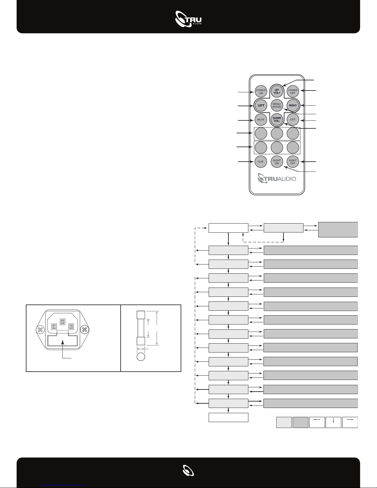
6. 5-way Binding Posts: Connect your subwoofer here.
Minimum impedance of the load is 4 ohms. Multiple
subwoofers can be connected if the combined load
impedance is 4 ohms or greater.
7. Voltage Selector Switch: The amplifier can be
used on 110~120V (60Hz) or 220~240V (50Hz) line
voltage. To change the operating line voltage, turn
the power off using the power button and unplug
the power cord. Remove the plastic cover screws
and the plastic cover over the voltage selector
located on the rear of the amp. Set the switch to the
correct position for the line voltage in your country.
Replace the plastic cover and screws over the
voltage selector switch.
NOTE: If required, remove the IEC line cord and
replace with an IEC AC cable that matches the AC
wall socket, this should be a 10A rated cable. When
the voltage selector switch is changed, the fuse
must also be changed to continue to provide
protection to the amplifier.
8. Power Cord Receptacle: The supplied power
cord needs to be connected to this receptacle in
order for the amplifier to work properly.
9. Fuse Holder: This is the power fuse access.
WARNING! In the event the fuse must be replaced,
the replacement fuse must match exactly the
original fuse value or damage to the amplifier may
result. Use a 8A 120V or 4A 240V fuse.
CAUTION! Before replacing the fuse, disconnect
the power cord from the power receptacle.
Remote Control
Power ON
Scroll Left
Mute
Memory
Recall Memory
Flat
STORE1STORE2STORE
RECALL1RECALL2RECALL
TRU-S500DSP
Control Flow Chart - SUB Mode
Normal
FLAT, 16, 20, 25, 31, or 40 Hz
40 ~ 160 Hz
6, 12, 18, 24, 30, 36, or 48 dB
Preset 1, 2, 3, 4, 5, 6, 7, 8, 9, 10
0°, 45°, 90°, 135°, 180°, 225°, 270°, or 315°
OSD
Time Out
Subsonic/ Freq.
Crossover/ Freq.
Crossover/ Slope
Presets
Phase
Volume
Volume Up/
Scroll Up
Power OFF
Scroll Right
Menu/Enter
Exit
Volume Down/
3
3
Scroll Down
Night OFF
Night ON
0,-1,-2,-3,-5,-6,-7,-9,-11,-13,
-15,-17,-19,-23,-27,-31,-35,
-39,-43,-49,-55,-61,-67,-73,
-79,
REMOVE FUSE HOLDER HERE
NOTE: A spare fuse is also
located in this holder
10. Removable Feet: The amplifier feet can be
removed as required for rack mount installation.
10MM
(±2.0)
5.2MM
(+0.1/-0.2)
20MM
(±0.5)
Night Mode
Auto Off
Mode select
External Trigger
Lock Setting
Memory Store
Memory Recall
Normal
Disable, Enable
Disable, 5, 10, 15, 20, 25, or 30 min
SUB, LFE (bypass LPF)
Off, On
Disable, Enable
Mem1, Mem2, or Mem3
Mem1, Mem2, Mem3, or Default
Function
Adjust
Name
Left Turn Right Turn
Value
Enter Key
Page 3
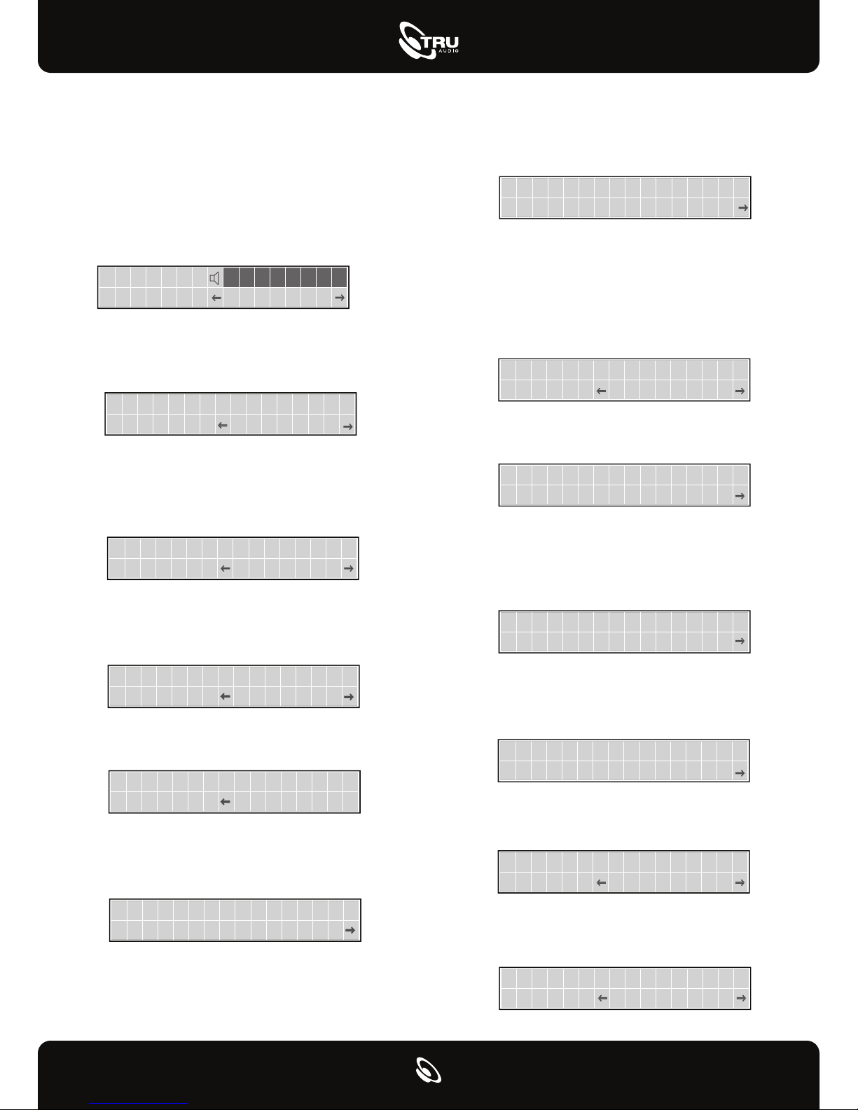
LCD Display Screens and Functions
Normally, the LCD display will show the status for a
number of settings as well as the volume level and a
flashing output level bar display.
Volume Control: Adjusts the output of the system.
The volume control should be set to achieve similar
volume levels from both the main speakers and
subwoofer.
Volume
0dB
Volume Control
Subsonic Control: This allows the user to select the
frequency at which they wish to cut off the
high-pass audio signal.
Subsonic
19HzFreq.
Subsonic Control
Crossover / Frequency: This allows the user to
select the frequency at which they wish to cut off
the low-pass audio signal. This feature only
available in Sub Mode.
C r oss ove r
24d B
100H zF r e q .
Crossover Frequency
Crossover / Slope: This allows the user to select
the slope for the crossover. This feature only
available in Sub Mode.
Crossover 120Hz
Slope 24dB
Crossover Slope
Preset Mode: There are presets for all TruAudio
subwoofers.
Preset Mode
User
EQ Mode
Phase Control: This feature is used to adjust the
subwoofer’s acoustic phase to match that of the
main speakers.
Phase
0 °
Phase Control
Night Mode: Limits the dynamic range of the
amplifier so the louder context of the source signal
is reduced. This feature allows the user to select
night mode. Choose enable or disable.
Night Mode
Disable
Night Mode
Auto Off: This feature allows the amplifier to turn
itself off when not in use. With the function set to
active, the amplifier will monitor its input signal. If no
signal is present the amplifier will shut down and go
into standby mode. As soon as a signal is present,
the amplifier will turn itself back on.
Auto off
15 min
Auto Off
Mode Select: This allows the user to select a mode.
Set values contain: SUB or LFE.
Mode select
SUB
Mode Selec t
External Trigger: This allows the user to select the
enable external trigger function. Press and hold the
navigation control knob with the power switch in the
ON position to change.
External Trigger
OFF
External Trigger
Lock Setting: When this function is active, all
settings will be protected until disabled. Values are:
Disable or Enable.
Lock setting
Disable
Lock Setting
Memory Store: This allows the user to select the
memory bank. There are three memory banks.
Memory Store
Mem 1
Memory Store
Memory Recall: This allows the user to recall
settings saved using the “Memory Store” function.
Memory Recall
Mem 1
Memory Recall
Page 4
TRU-S500DSP
Specifications
Total Harmonic Distortion (THD):
Power Output:
Equalizer:
Adjustable Low Pass Crossover:
Adjustable Slope:
Line Level Input Sensitivity:
Phase Control:
Auto Turn-on Sensitivity:
Extrenal Trigger:
Thermal Protection Circuit:
Night Mode:
Remote Control:
Single Ended and Balance Input:
Dimensions (with rack mounts):
Trouble Shooting
SYMPTOM POSSIBLE CAUSE AND TEST PROCEDURE
1. Check that the amplifier is plugged into an A/C power
outlet and has power.
No sound from
the subwoofer(s).
Sound from at least
one subwoofer, but
not the other(s).
2. Make sure that the subwoofer(s) is/are connected
properly.
3. Make sure there is an audio signal from pre-amp /
receiver.
1. Verify that all wires are properly connected.
2. Verify that all connections are complete
and secure, with no stray wires contacting
other terminals.
3. Check each individual subwoofer
500 Watts (RMS @ 4Ω)
<1%
Adjustable Built-in 10-Band
(-6dB to +6dB)
40Hz to 160Hz / 1 Hz Increments
6dB-40dB
190 mV
0 to 315
° / 45° Increments
3 mV @ 50 Hz
12V
Yes
Yes
Yes
Yes
19” W (483mm)
1.75” H (45mm)
10.38” D (264mm)
Weight:
16 lbs. (7.26kg)
Fuse:
8 Amp (120V)
4 Amp (240V)
TO PREVENT FIRE OR SHOCK HAZARD. DO NOT EXPOSE THIS APPLIANCE TO RAIN OR MOISTURE.
THIS APPLIANCE SHALL NOT BE EXPOSED TO DRIPPING OR SPLASHING WATER AND THAT NO
OBJECT FILLIED WITH LIQUIDS SUCH AS VASES SHALL BE PLACED ON APPARATUS.
Electricity is used to perform many useful functions, but it can also cause personal injuries and
property damage if improperly handled. This product has been engineered and manufactured
with the highest priority on safety. However, improper use can result in electric shock and / or
fire. In order to prevent potential danger, please observe the following instructions when
installing, operating and cleaning the product. To ensure your safety and prolong the service
life of your Sound Bar, please read the following precautions carefully before using the product.
1. Read these instructions.
2. Keep these instructions.
3. Heed all warnings.
4. Follow all instructions.
5. Do not use this apparatus near water.
6. Clean only with dry cloth.
7. Do not block any ventilation openings. Install in accordance with the
manufacturer’s instructions.
8. Do not install near any heat sources such as radiators, heat registers, stoves, or
other apparatus (including amplifiers) that produce heat.
9. The battery shall not be exposed to excessive heat such as sunshine, fire
or the like.10. Do not defeat the safety purpose of the polarized or grounding-type plug.
Apolarized plug has two blades with one wider than the other. A grounding type
plug has two blades and a third grounding prong. The wide blade and the third
prong are provided for your safety. If the provided plug does not fit into your
outlet, consult an electrician for replacement of the obsolete outlet.
11. Protect the power cord from being walked on or pinched particularly at the plugs,
convenience receptacles, and the point where they exit from the apparatus.
12. Only use attachments/accessories specified by the manufacturer.
13. Use only with the cart, stand, tripod, bracket, or table specified by the
manufacturer, or sold with the apparatus. When a cart is used, use
caution when moving the cart/apparatus combination to avoid injury
from tip-over.
14. Unplug this apparatus during lightening storms or when unused for long periods
of time.
15. Refer all servicing to qualified service personnel. Servicing is required when the
apparatus has been damaged in any way, such as power-supply cord or plug is
damaged, liquid has been spilled or objects have fallen into the apparatus, the
apparatus has been exposed to rain or moisture, does not operate normally, or
has been dropped.
16. The mains plug or an appliance coupler is used as a disconnect device, the
disconnecting device shall remain ready operable.
SUBWOOFER and ELECTRONIC PRODUCT WARRANTY
All subwoofers and amplifiers have a limited 5 year warranty. This warranty includes 5 year parts and repair labor on all
components. The warranty extends only to the original purchaser of the product and not to any subsequent owner. TRUAUDIO’s
obligation under these warranties is limited to repairing or replacing any component found defective in material or workmanship
under normal conditions of use with an equal and/or current product. These warranties shall not apply to products which have been
abused, modified, or disassembled. Products to be repaired or returned under this warranty must be returned to the factory
through an authorized TruAudio dealer with all transportation and insurance charges prepaid.
It is the policy of TRUAUDIO to continuously incorporate improvements into our products. All specifications are subject to
change without notice. If you have any questions regarding this or any other TRUAUDIO products, please visit
www.TruAudio.com or contact us:
Office: 1-888-858-1555, Monday-Friday 7 am - 6 pm MST.
Email: [email protected]
SoundVision Technologies dba TRUAUDIO
 Loading...