

Page 1
User Manual
RM-12
Powered Subwoofer
RM-12
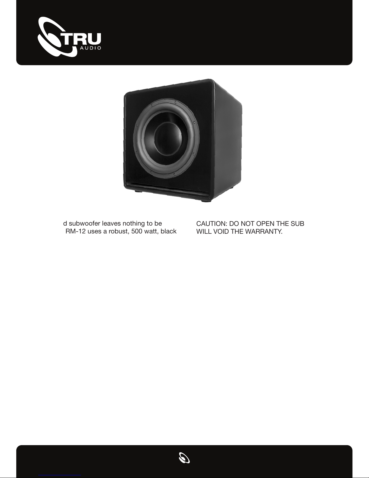
This powered subwoofer leaves nothing to be
desired. The RM-12 uses a robust, 500 watt, black
anodized aluminum woofer, driven by a powerful
A/B amplifier built exclusively for this cabinet and
driver array.
The RM-12 sounds fantastic with all TruAudio
architectural speakers, making combining different
models in an AV system simple. Additional speakers can be added to a system with the confidence
that the speakers will remain balanced. With over 2
years of engineering and testing, the RM-12 completes the TruAudio theater package.
Contents
The RM-12 includes: Subwoofer cabinet and grill,
power cord, instruction manual, a warranty card,
and (4) heavy-duty plastic feet attached to the
bottom of the cabinet.
Unpacking and Inspection
Inspect your subwoofer immediately upon opening
for any kind of damage. If for some reason damage
has occurred, please contact your Dealer or TruAudio immediately. We recommend that you retain the
packaging in case a need arises for you to transport
your speaker.
CAUTION: DO NOT OPEN THE SUBWOOFER. THIS
WILL VOID THE WARRANTY.
To reduce the risk of electrical shock and fire, do not
remove the amplifier panel from the back of the
cabinet or the subwoofer from the front of the
cabinet. There are NO fuses or serviceable parts.
All service to this product MUST be done by a
TruAudio Authorized repair center.
Before installing, please read the following
instructions:
• Always turn off the power of your
receiver/preamp and the powered subwoofer
• When turning your amplifier/receiver on, make
sure your volume is turned all the way down
• Never expose the subwoofer to excessive cold,
heat, humidity, or direct sunlight
• This device should never be used in, on or near
water due to risk of fatal shock
• DO NOT attempt to open or dismantle this
subwoofer
• The subwoofer should always have plenty of air
flow to reduce the chance of over heating
Page 2
Controls
115/230V
FUSE TYPE:
IN OUT
R L
POWER
ON
OFF
LR
INPUT
VOLTAGE
115
ON ON 90°
LFE
50Hz
AUTO
IN
LINE
OUT
IN
SPEAKER
LEVEL
OUT
CAUTION:
ATTENTION:
OFF 180°0°
25Hz
BOOST
PHASE
100Hz
FREQUENCY
CAUTION
MIN MAX
LEVEL
INPUT CONNECTIONS
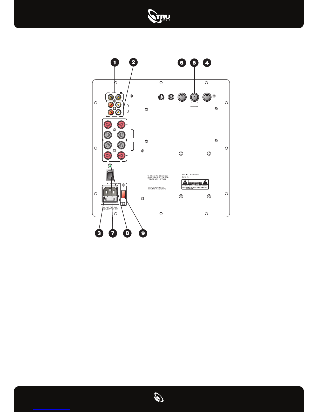
1. LFE Direct Input
RCA jack that will accept a signal from the mono
LFE (Low Frequency Effects) output on a pre-amp or
receiver that is equipped with a dedicated sub bass
output. This input bypasses the amplifier’s own
internal low pass filter circuitry, relying instead on
the processed output provided by the source
equipment. This would be the recommended
connection for most home theatre surround sound
receivers and pre-amps. We would also suggest the
use of the LFE input when an external line level
electronic crossover or frequency dividing
network is used.
2. Left/Right Inputs
RCA style jacks that will accept standard line level
inputs from a pre-amp level source. They will accept
a stereo signal and internally combine it into mono.
Both left and right input jacks must be connected to
the source in order to drive the amplifier to full
output. The use of a “Y” cord is suggested if a
mono source is all that is available.
3. Power Input
This unit features an IEC grounding type power
input connector. The IEC inlet connector also
features an integrated fuse holder that contains the
AC line fuse. For 230 V input, remove the fuse
holder, swap fuses, and re-install. In most
230 V applications a separate power cord will be
required and is not included.
Page 3

CONTROLS/INDICATORS
4. Level
Match the amplifier’s input sensitivity to the output
of the pre-amp source. If the source output has a
variable control, we recommend that the user spend
a moment or two determining the best balance
between the two controls. When a
balance is found between low noise, linear level
control, and sufficient level to drive the amp to the
required output, the level knob can be considered to
be the “volume control” for the subwoofer system.
5. Low Pass Frequency
This control is used to establish the highest
frequency that the subwoofer will reproduce and
has a range between 50 and 100 Hz. Experiment
with the amount of “overlap” that you will experience when all speakers are playing in the same
range. This can be helpful when integrating the
subwoofer with the rest of the system and with the
room.
6. Phase
This knob helps to compensate for differences in the
acoustical and electrical characteristics between the
subwoofer and the main system speakers. The
relative locations of speakers in the system can
cause signicant disturbances in speaker interaction due to time delay issues, or the destructive
phase interferences that can occur at certain
frequencies.
NOTES ABOUT HUM
While this amplier has been designed to minimize
the possibility of hum in the subwoofer system, it is
still possible that a hum may occur in rare
circumstances. Safety grounding can create a path
for small amounts of 60 Hz energy to travel through
the line-level audio system. While not
dangerous, this energy can cause difculty with the
subwoofer auto signal sensing circuit, and will
interfere with the quiet enjoyment of your system.
The rst course of action should be trying to make
sure that all of the audio components are connected
to either the same electrical outlet, or at least into
the same circuit branch. Next, cable TV systems are
notoriously the culprit, so be sure to try disconnecting all coaxial feeds that are connected to the
system. If this solves the problem, install a coaxial
line isolator and reconnect the system. Worst case,
a line-level audio isolator/transformer connected to
the line-in of the subwoofer amplier can usually
solve the problem.
Cleaning the Subwoofer
All RM series subwoofers feature lightly textured,
durable paint nish. When needed, we suggest
cleaning with a damp cloth with water only. Do not
use any kind of abrasive cleaners or detergents.
7. Power Switch
This switch manually turns the unit on and off. When
switched to the on position, the unit will rst turn on
and be fully operational. After a period of 10-15
minutes without a signal the unit will go into “stand
by” mode.
8. Power LED
When the LED is illuminated green, the amp is in
“stand by” mode.
9. Input Voltage Switch
Switches the amp between 115v and 230v for use in
different countries or regions.
Page 4
RM-12
Specifications
Enclosure Design:
Frequency Range, Line In:
Frequency Range, LFE:
Input Sensitivity, Low Level:
Input Sensitivity, High Level:
Amplier Protection:
Cabinet Dimensions:
Speaker Type:
Driver:
Power, class D:
Inputs:
Outputs:
Cabinet:
Grill:
Available Colors:
High-end Powered Subwoofer
Front ring, ported cabinet, internally
braced
12” black anodized aluminum cone,
cast basket, long excursion, 2.5”
2-layer voice coil.
500 watt into 4 ohms with internal
amplier
20-220 Hz (+/-3 dB)
20-230 Hz (+/-3 dB)
150 mV (max) @ 100 Hz
3.5 V (max) @ 100 Hz
Line level RCA, speaker level
w/banana plugs, LFE line level RCA
Line level RCA, speaker level banana
plugs
Output protection circuit with relay
Real wood veneer, Built in St. George, UT
17.7” High (including feet)
17.0” Wide
16.2” Deep
Frame wrapped in black speaker cloth
Black in stock. Other colors available with
3 week lead time.
SoundVision Technologies dba TRUAUDIO
SUBWOOFER and ELECTRONIC PRODUCT WARRANTY
All subwoofers and amplifiers have a limited 5 year warranty. This warranty includes 5 year parts and repair labor
on all components. The warranty extends only to the original purchaser of the product and not to any subsequent
owner. TRUAUDIO’s obligation under these warranties is limited to repairing or replacing any component found
defective in material or workmanship under normal conditions of use with an equal and/or current product. These
warranties shall not apply to products which have been abused, modified, or disassembled. Products to be repaired
or returned under this warranty must be returned to the factory through an authorized TruAudio dealer with all
transportation and insurance charges prepaid.
It is the policy of TRUAUDIO to continuously incorporate improvements into our products. All specifications are subject to
change without notice. If you have any questions regarding this or any other TRUAUDIO products, please visit
www.TruAudio.com or contact us:
TruAudio
198 N Old Highway 91
Hurricane, UT 84737 USA
 Loading...