


Version 2013/2
Installation manual
Mamba II

CONTENTS
1. General info ..................................................................................................................................................................... 3
1.1. Design ....................................................................................................................................................................... 3
1.2. Principle of operaon ............................................................................................................................................... 3
1.3. Technical specificaon and condons ................................................................................................................... 4
1.4. Cable installaon requirment................................................................................................................................... 4
2. Fences ............................................................................................................................................................................. 5
2.1. Types of the fences .................................................................................................................................................. 5
2.2. Installaon opons and ps for assembly ............................................................................................................... 5
3. Installaon....................................................................................................................................................................... 6
3.1. Instalaon of the device ........................................................................................................................................... 6
Important noce ......................................................................................................................................................... 6
3.2. Cabeling .................................................................................................................................................................... 8
Preparaon of RG59 cable .......................................................................................................................................... 9
Preparaon of sensve cable ...................................................................................................................................... 9
Cable connecon ......................................................................................................................................................... 9
Cable terminaon ..................................................................................................................................................... 10
3.3. Controls .................................................................................................................................................................. 10
DIP switch .................................................................................................................................................................. 10
Rotary switch............................................................................................................................................................. 11
3.4. Tesng mode .......................................................................................................................................................... 11
3.5. First start ................................................................................................................................................................ 12
5. Programming soware ................................................................................................................................................. 13
5.1. Instalaon............................................................................................................................................................... 13
5.2. Control .................................................................................................................................................................... 13
SECTION A ................................................................................................................................................................. 14
SECTION B ................................................................................................................................................................. 17
SECTION C ................................................................................................................................................................. 18
6. SERVIS............................................................................................................................................................................ 20
Installaon manual – Mamba II
1. GE NERAL INFO
1.1. DESIGN
MAMBA perimeter system is primary designed to secure perimeter of the objects, especially fences. It can be used for
underground installaon, concrete walls, the protecon of solid objects such as solar panels etc.
This alarm system generates an alarm when intruder trying to overcome a fence or any aempt of intrusion. System
also testing constantly overall integrity of the cable (disconnecon, short-circuit).
1.2. PRINCIPLE OF OPER AT IO N
The general principle is based on fact that the detecon cable
generates small triboelectric signal. This signal (stac
electricity) is due to fricon between the dielectric and the
copper core of the cable. Deformaon of the cable and
fricon in the cable will generate signal in the moment of the
intrusion. If the cable is well connected to the fence all fence
working like sensive intrusion detector.
Whenever the intruder will aempt to handle any fence or
cable, the system immediately generates an alarm signal.
The sensor
is
typically mounted directly to the fence or fence posts (see. Chapter 1.4 Installation requirements and
procedures). Sensing cable is securely fastened to the fence using a plasc or metal cable es. The number of strips is
an important parameter for the overall system behaviour and sensivity. Generally: smaller number of the strips is
used to fix the cable it will decrease the sensivity of the system and it may cause false alarms.
System is proofed a recommended to use with shielded cable category
5 – it
means cable “FTP Cat 5E“ or “STP Cat
5E“. They can also be used in other types of communicaon cables that are suitable for its characteriscs parcularly
resistance in an outdoor environment and also their construcon. The system also supports a special kind of sensing
cable called “vibrocable” which is typically used for fixed concrete fences or underground installaons. Vibrocable and
other non-recommended cable consult with your supplier.
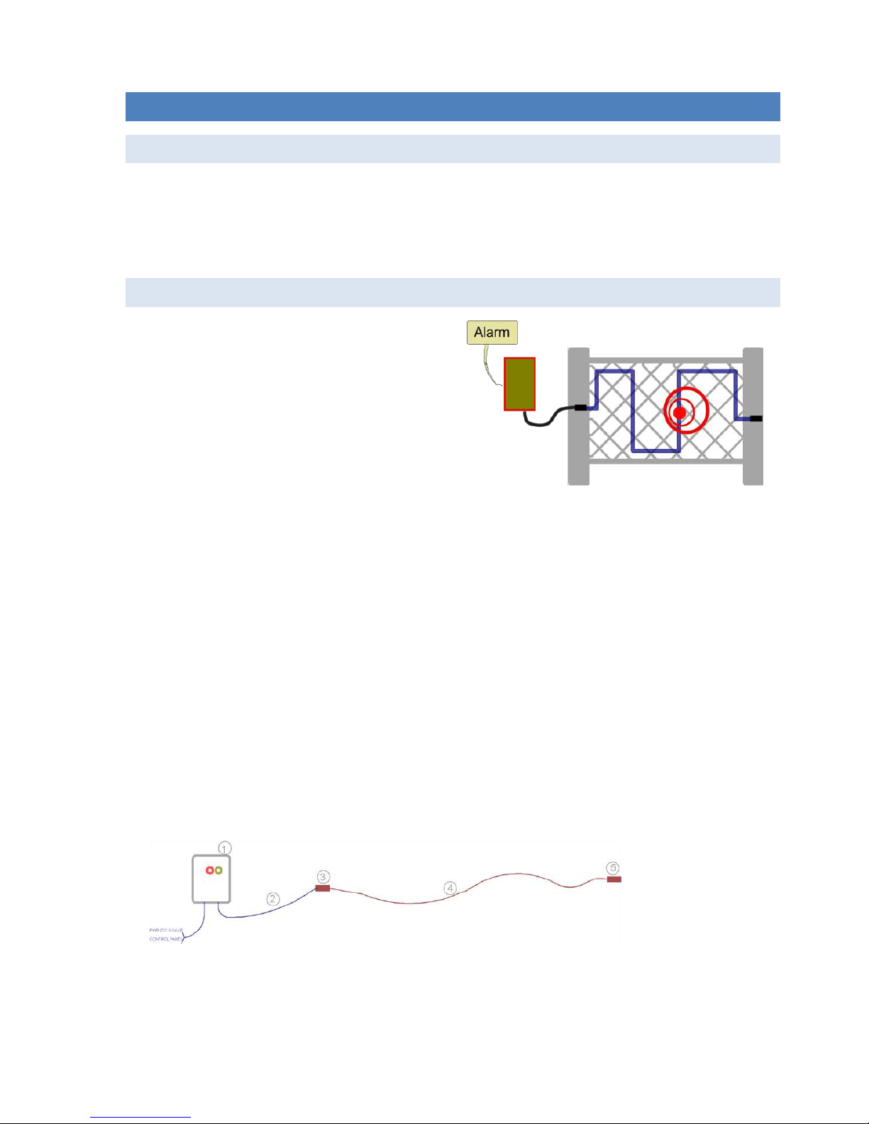
The system consists of the following components (see. F
ig.
1):
sensor MAMBA (1)
non sensive cable (2)
cable juncon box (3)
sensive cable (4)
terminaon (5)
Fig. 1: Diagram of the system
Installaon manual – Mamba II
1.3. TECHNICA L SP ECIFICATION AND CO ND TITIONS
Sensor contain two different kind of outputs - Alarm (burglar alarm) and two outputs Tamper (disrupon of integrity
of the cable, alarm from lt detector, low voltage etc.).
Package content:
Mamba sensor
1 pcs
Juncon
1 pcs
Terminaon juncon
1 pcs
Terminator
1 pcs
Quick installaon guide
1 pcs
CD with soware and documentaon
1 pcs
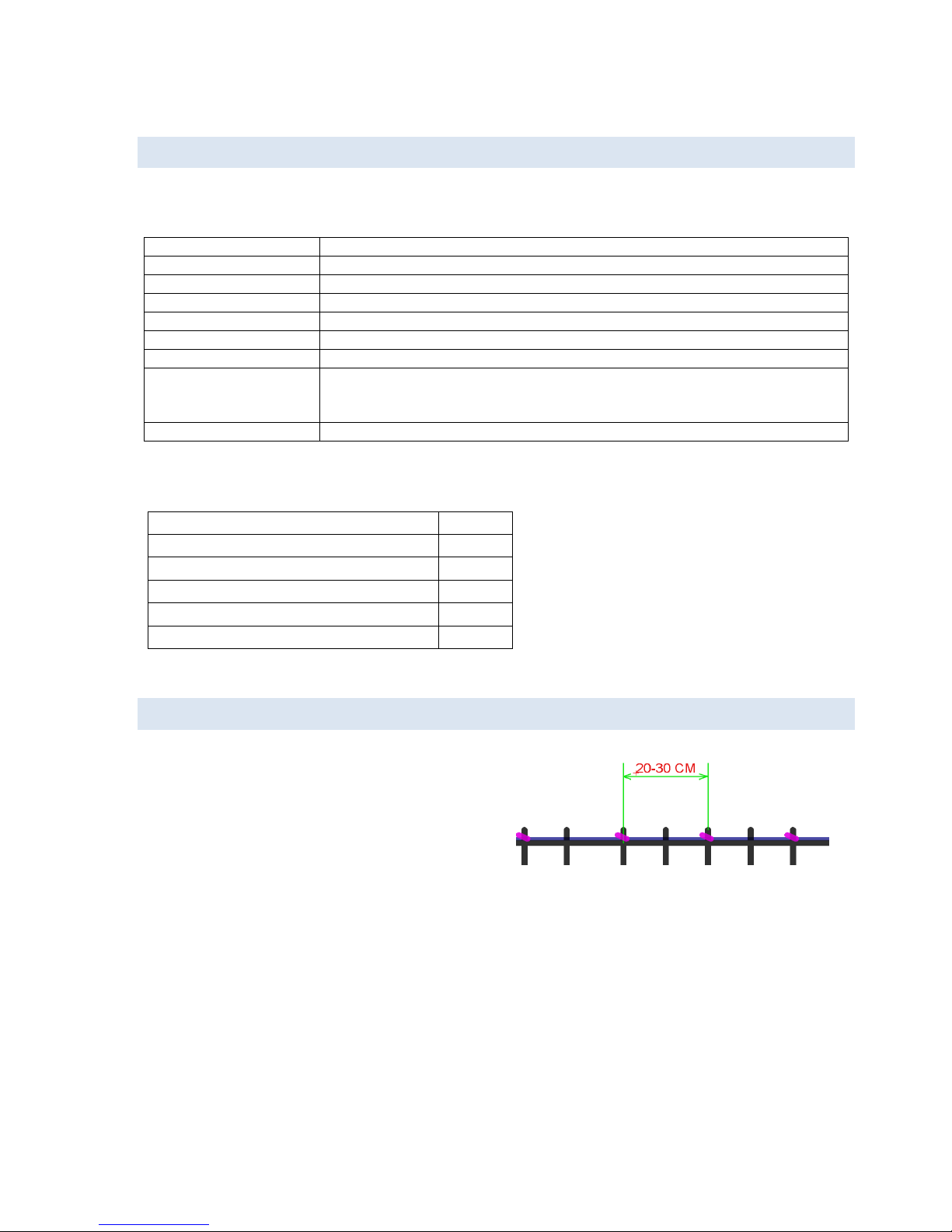
1.4. CABLE IN ST ALLA TION RE QUIRMENT
For mounng on the fence, use plasc or metal straps with UV
resistance at a distance of 20-30 cm. Right and stable coacon
to the fence is one of the most important parameter of
stability of the system. Cable and the fence has to be one
compact unit. Important is also Important is a sufficient cable
tension and uniform strength of ghtening strips. It is
advantageous to use a special mounng strips tongs. If the
cable is routed through a column or other reinforcement,
set higher tens
ion level
on the tongs.
Do not connect detecon cable directly to the Mamba unit, use non-sensive cable connected in the juncon box
(see. Figure 1 - Diagram of the system). Non-sensive cable is typically a coaxial cable type RG59 without aluminium
foil shielding. Best non-sensive cable is the RG59 cox with cooper mesh dielectric shielding.
Power consumption:
Max. 40 mA
Voltage supply:
DC 9-25V
Operating temperature:
-40°C ~ + 80°C
Protective rating:
IP67
Bus type:
RS485 (speed 19 200 baud)
Bus range:
2000m
Tilt detector:
3 axis ±3G
Outputs:
Alarm – NC contact (normally close contact)
Tamper I – NC contact (normally close contact)
Tamper II – NC contact (normally close contact)
Outputs features:
Impedance 8Ω, 50V /150mA
Fig. 2: Strips installation
Installaon manual – Mamba II
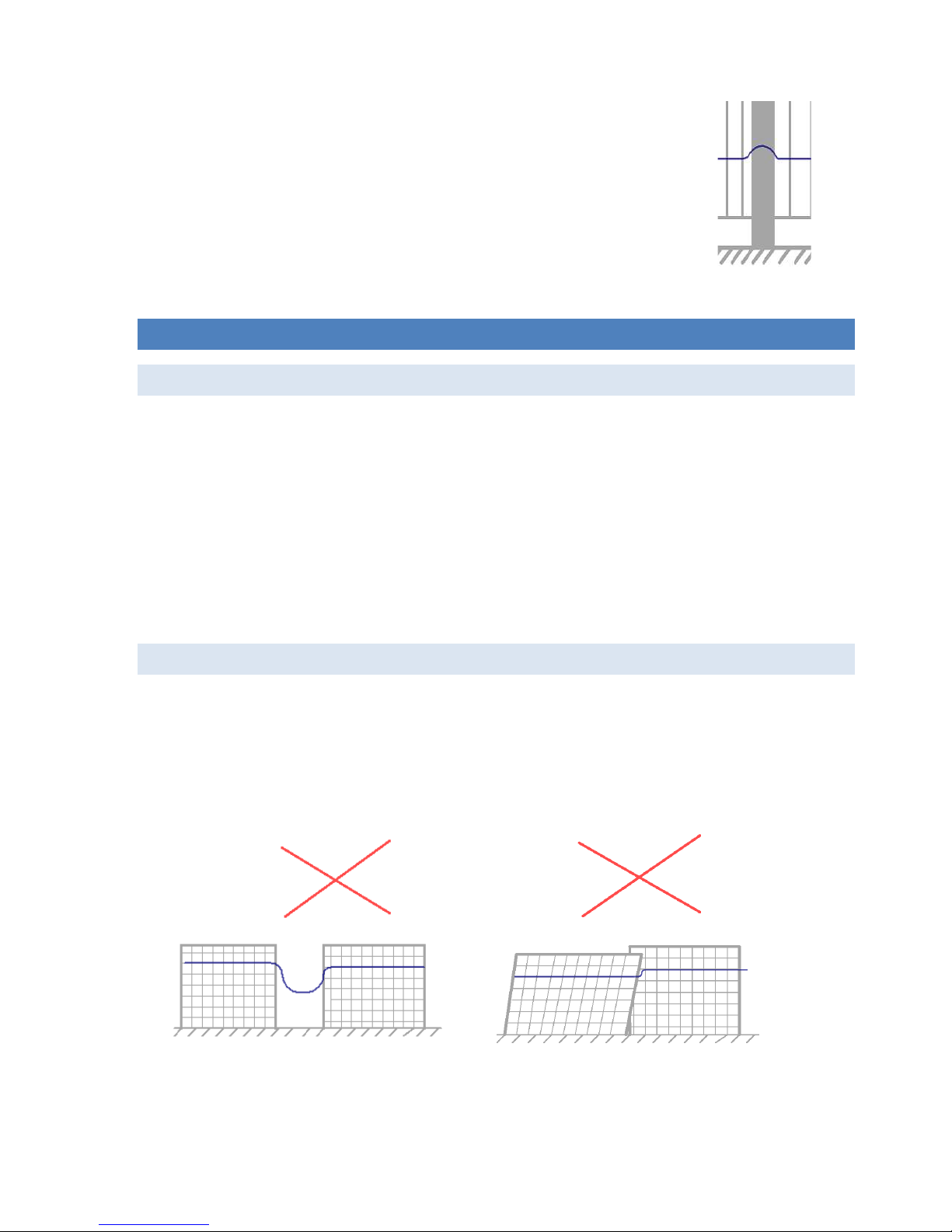
Do not
stress cable when crossing fence posts (see. Fig. 3). In this case, leave the cable non-
stressed due to dilataon of the cable and the movement of blocks of the fence .
Make sure that non-sensive cable RG59 is hidden and possibility of sabotage is eliminated to
the minimum.
2. FE NCES
2.1. TYPES OF TH E FE NCES
System is able to work properly with following types of the fences:
Knitted wired fence
Wired fence
Concrete fence or wall
Solid metal fence
Wooden fence
Barber fence
There is possibility to use standard mounng method in most cases for the wired fences. If you would like to install
system to the concrete or other solid fence, please contact producer or distributor to discuss installaon method.
2.2. INSTALLATION O PTIONS AND TIPS FOR AS SEMBL Y
Install the sensor directly to the fence post.
Wired fence has to be strong around the complete perimeter and the strips has to be stressed everywhere in the
same tension. Try to keep same installaon condion in full length of the fence.
Do not install the sensor on the damaged fence.
Fig.4: Bad installation conditions
Fig. 3: Crossing the fence post
Installaon manual – Mamba II
Indi
vidual segments of the fence must be stable also between each other. Sensive cable must never be free - always
has to be firmly aached to the fence.
When the system is properly installed, the alarm is generated when the fence is deformed, such as an aempt to
overcome or any other aack.
Within eliminaon of false alarms try to secure the fence to prevent movement in the wind.
3. INSTALLATION
3.1. INSTALAT IO N OF THE D EVICE
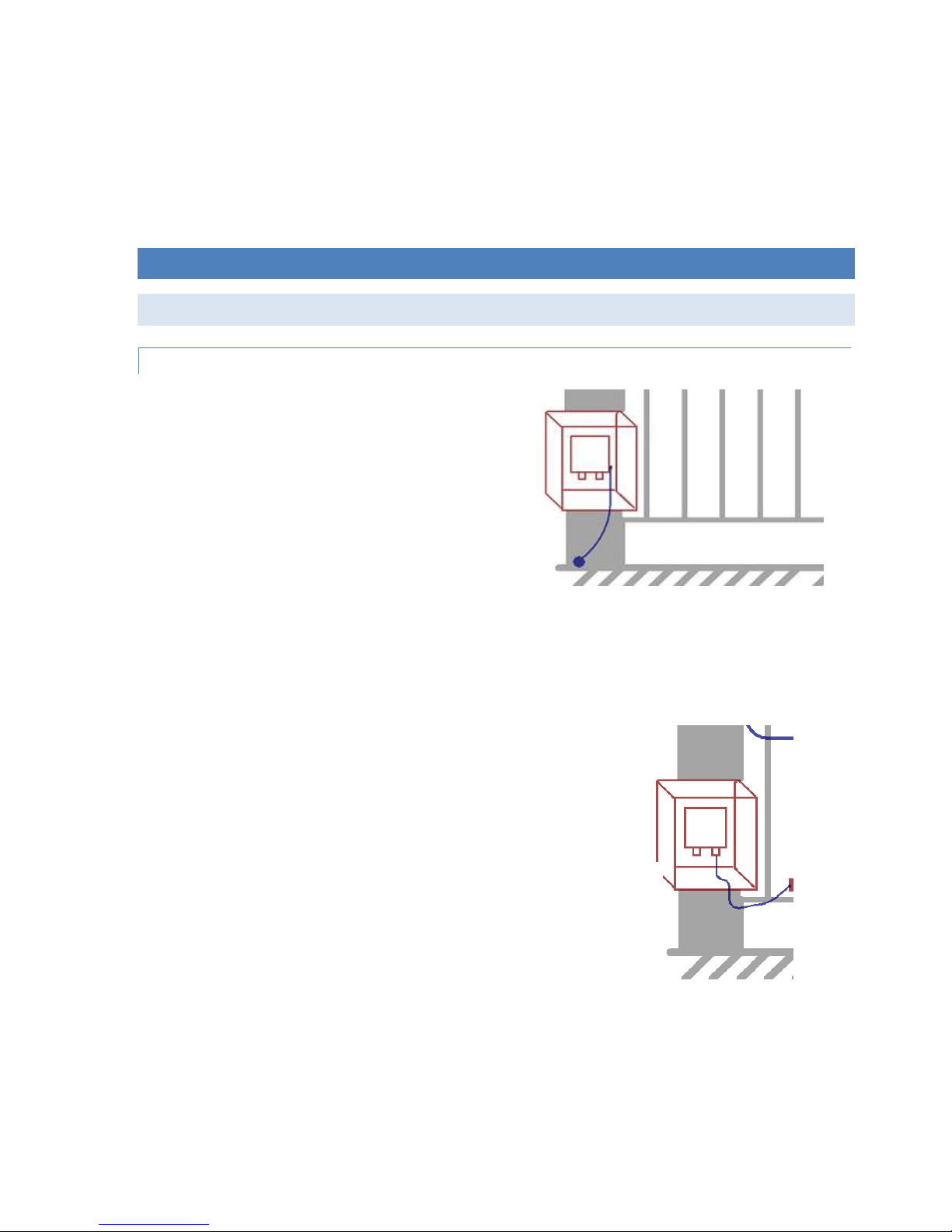
IM PORTANT NOTICE
Please pay aenon to the grounding of the sensor.
Detector should not be grounded more than once. Please
ground the sensor in one place possible shortest cable
(minimum diameter of 1 mm) - see. Fig. 5.
Minus pol (-) of power supply IS NOT grounding of the
sensor.
Before connecng the sensor to the installed cable, be sure
that the impedance between the cable shield and wires is
more than 20 MΩ.
Do not install the system in bad weather condion with high humidity (rain and snow). It is v
er
y important not to
leave the stripped cable in water and is necessary to avoid any penetraon of humidity into the cable. In these cases
are helpful usage of lubricant, which prevents the penetraon of moisture and displaces it.
If you want to increase system robustness against sabotage place sensor in another plasc or metal juncon box. It is
also possible to fit it into other elements of the system (emergency buon, backup
power supply, the source backup, security system
conc
entrator, etc.) - see. Fig. 6.
Fig. 6: Another mounting box

Installaon manual – Mamba II
Boa
rd schematic:
DIODY:
AL
ALARM
T1
TAMPER 1 (reed relay always + cable
terminaon in default)
T2 TAMPER 2 (lt detector in default + low
power – default < 9V)
Green
Power ON – in order
DIP switch:
1
Extra sensivity ON / OFF
2
Test mode (acvaon of tester)
3
Tamper contact – reed relay (ON -
acve, OFF deacvated reed relay on
main board)
4-8
BUS address (binary 1-32) see. Secon
3.3 Controls
Rotary switch:
0-9
Sensivity (0 - lower, 9 - higher)
Terminals:
IN
Connecon of sensive detecon
cable. Terminal IN - wires and GNDA shield.
GNDA
NC1
Output ALARM (normally close)
NC1
NC2
Output TAMPER 1- reed relay always +
cable terminaon in default)
NC2
NC3
Output TAMPER 2 (Tilt detector in
default + low power – default < 9V)
NC3
DI
Input for decreasing of sensivity
(acvaon by connecon to GND2)
GND2
BUS terminals RS485. Galvanically
isolated terminals. Set address on DIP
switch before use!
485+
485-
PWR(+)
Power 9-25V DC
PWR(-)
Fig.7. Mainboard MAMBA II -1

Installation manual – Mamba II
3.2. CABELING
For wire fences manufacturer recommends using a standard shielded cable FTP Cat 5E for outdoor use with resistance
to UV radiation. For fixed fences and underground installation is necessary to use special VIBRO cable.
Connection of the cable and the sensor
Use the special joints for connecting cables and sensor MAMBA.
There are two types of cable connectors. The first is for transform sensitive cable to non-sensitive and the second type
is for terminating of cable.
Fig.8: Cable connection
Cable joint (see.Fig.9) is designed to transform sensitive cable (FTP Cat5) to non-sensitive (RG59). It can be also used
for repairing a damaged cable.
Fig.9: Cable joint

Installation manual – Mamba II
PREPARATION OF RG59 CABL E
When preparing the cable RG59 follow Figure 10:
unscrew the end of the joint;
put the rubber seal from the cable gland;
remove the isolation of the cable RG59 at distance 42 to 44 mm;
split shielding to separate wires;
wrap the shielding by tinned wire and keep 35-40 mm for
connection to a terminal;
remove the centre cable isolation and keep 15-20 mm;
fold the centre cable in half due to the amplification of diameter
of the cable. Keep about 12 mm because of terminal connection;
ensure that the length of both ends is at least 6 mm.
PREPARATION OF SE NSTIV E CABLE
Preparation of sensoric cable describe following Fig.11):
unscrew the end of the joint;
put the rubber seal to the cable from the cable gland;
remove the isolation from 35 to 40 mm;
cut off the isolation foil about 9-11 mm from the left edge of
isolation;
cut off the shielding wire about 9-11 mm from the left edge of
isolation;
bend the cable shield (including foil) toward the existing
isolation;
wrap the shielding with tinned wire for a distance of 35-40 mm;
remove the isolation of all central wires at around 30- 32 mm;
put all centre wires together;
ensure that the length of the central wires are at least 6 mm.
CA BLE CONNECT IO N
Fig.12: Cable joint for connection of sensitive and non-sensitive cable
Fig. 11: Preparation of detection cable
Fig. 10: Preparation of RG59 cable

Installation manual – Mamba II
CA BLE TERMINATI ON
Please observe the following instructions for terminating cable
For the termination of the cable, use the provided cable joint. For termination (balancing) use the supplied cable
termination element (resistor) and connect it between the shield and the centre wires (signal and ground).
Fig.13: Cable joint for termination of the cable
3.3. CONTROLS
DIP SWITCH
1
Extra sensitivity
2
Activation of test mode (see. Chapter 3.4. Testing mode)
3
Switch ON / OFF reed relay on mainboard
4-8
Address for RS485 BUS
Switch no. 1 is used for main level of sensitivity. If switch is ON – sensor working in HIGH level of sensitivity. This
sensitivity is used mainly for solid fences.
Switch no. 2 see Chapter 3.4. Testing mode
Switch no. 3 switching ON / OFF reed relay on mainboard, which is connected in serial with output NC2. Connection of
the reed relay is fixed by hardware connection and it is not possible to change it by control software. If you do not
need to use reed relay - toggle Switch no.3 to ON position.
Switch no. 4-8 are used for settings of BUS address. This is described in the following table:
DIP 1 2 3 4 5 6 7 8
DIP 1 2 3 4 5 6 7 8
address 1
●
address 17
● ● address 2
●
address 18
● ● address 3
● ● address 19
● ● ●
address 4
●
address 20
● ● address 5
● ● address 21
● ● ●
address 6
● ● address 22
● ● ●
address 7
● ● ●
address 23
● ● ● ● address 8
●
address 24
●
●
address 9
● ● address 25
● ● ●
address 10
● ● address 26
● ● ●
address 11
● ● ●
address 27
● ● ● ● address 12
● ● address 28
● ● ●
address 13
● ● ●
address 29
● ● ● ● address 14
● ● ●
address 30
● ● ● ● address 15
● ● ● ● address 31
● ● ● ● ●
address 16
●

Installation manual – Mamba II
ROTARY SWITCH
To accurately sensitivity settings, use the rotary switch 0-9. To set the lowest sensitivity set to 0 and the highest
sensitivity in the range, set 9. If you change sensitivity in the control software, system will store this setting up to next
change using a rotary switch. The last position is always written into an EPROM - whether hardware or software.
To set the detection methods for different types of fences and installing it is necessary to use the programming
software (see. Chapter 4. Programming SW)
3.4. TESTING MO DE
The device has a built-in alarm signal level, which will be very helpful for set up of the system. To activate it, turn DIP
switch no. 2 to the ON position.
1
Extra sensitivity
2
Activation of test mode
3
Switch ON / OFF reed relay on mainboard
4-8
Address for RS485 BUS
In this mode, the following LEDs on the board has different meaning:
AL
Alarm
T1
Prealarm
T2
Not used in test mode
Green
Not used in test mode
When adjusting the sensitivity, proceed as follows:
Switch ON Test mode
Turn off extra sensitive mode (DIP switch no. 1).
Set the rotary switch to the middle sensitivity.
Check the signal level by mechanical deformation of sensoring cable. Signal indicator shows the level of signal -
the more green lights on the bar chart means the greater signal level. The yellow LED T1 indicates Prealarm and
red AL indicates an alarm signal.
The sensor needs always 10 seconds after an alarm to regenerate and calibrate the detection algorithm.
Therefore, make individual tests always with a slight time spacing!
Now you can test the sensitivity of the system: throw the object with approximate weight of 2 kg on the fence
(not directly on the cable) and the system should not raise the alarm - red LED AL does not light. Is necessary to
always watch level on the indicator bar.
When the fence is loaded by object with weight more than 25 kg system must raise the alarm - red LED AL lights.
Is necessary to always watch level on the indicator bar.
Adjust the sensitivity by rotary switch or use DIP switch no. 2, until you met the previous two terms.

Installation manual – Mamba II
Resistance to strong winds can be observed in the test mode in windy weather. The signal level indicator should
remain spontaneously in the wind at more than 3 pieces of signal. You can check in the windy weather also the
stability of the tension mesh fence and stability of all parts of the fence. Remove the mechanical deformation of
the cable.
3.5. FIRST START
Switch ON the sensor
When the power supply is connected – first is green LED light, then blink yellow and finally red LED.
Now is a slight delay (about 1 second) tested the integrity of the sensor and cable.
If the cable is connected, integrity of the cable is OK and is properly terminated, after a while, the yellow LED goes
out.
If the sensor is working properly, the red LED will also be illuminated for approximately one second.
Now is system ready for use.
The described behaviour is valid if the sensor in the factory setting. The control software can change the
configuration of fault LEDs. Setting fault diodes is derived from the software settings.
The described behaviour is valid if the sensor in the default factory setting. The control software can change the
configuration of trouble LEDs. Software settings can change status of trouble diodes.

Installation manual – Mamba II
5. PROGRA MM IN G SOFTWARE
5.1. INSTALAT ION
Run the installation file "setup.exe" and follow the instructions during installation. After installation, you create a
shortcut "Mamba Soft 2" in the Start menu. Start the software.
5.2. CONTROL
After starting the main screen appears:
Fig. 14: Main window
1. Connection settings – you can set the parameters of the serial port for connection in this section. If you
connect locally or via RS485, locate the transmitter in the list of loaded devices. The software automatically
detect all devices connected to your computer. This procedure working only when the software starting, so
your converter has to be connected to a PC before start of the software.
Setting the address of the sensor is described in chapter 3.3. Controls
Speed of communication BUS is in default set to 19 200 Baud – do not change this setting. Is necessary to set
right address on RS485. This setting has to be realized by hardware DIP switch 4-8.
2. Connection to the sensor – Press Connect to connect the sensor and the software automatically retrieves all
values from the sensor EPROM memory. After this operation, all settings in the menu start to available and
status of the sensor will be displayed.
WARNING!!!
All the values that you set in control software, rewrite manually adjusted values of the rotary switch on the
mainboard. And opposite - Each additional manual change on the rotary switch rewrites the software set
parameters. The software always reads the last set values from EPROM memory either HW or SW.
1 2 3
5
SECTION C1
SECTION B
6
SECTION A
4

Installation manual – Mamba II
3. Communication signalization – signalization of RX and TX
4. Status bar – displays the current software activity, and displays the results of all activities of the SW.
5. Language settings – here it is possible to choose the language setting from the available languages.
6. Upgrade – upgrade of existing version to a newer software version. Upgrade procedure is automatic. During
this operation, software will be shut down and the last version will start automatically. For this operation, it is
necessary to have an Internet connection.
SE CTION A
1. Detection TAB – In this section you can set the sensor detection algorithm for the particular type of
installation:
WIRED FENCE – this setting is right for most types of the flexible fences.
SOLID FENCE – Sensitive algorithm for fences with minimal cable deformation
CONCRETE FENCE – For use on walls using a special VIBRO cable
SOLAR PANELS – To protect permanently installed objects - e.g. Solar panels to protect against
tampering and disassembling
UNDERGROUND INSTALLATION – This option is suitable for most sensitive installations and
making a change to the very sensitive detection algorithm that can detect even minor changes
and is therefore suitable for special applications in underground installations. In these types of
installations are used extra sensitivity DIP switch no. 1.
1 3 4 5 6
2 7 8

Installation manual – Mamba II
2. You can define some features of the sensor in this section:
Setting of sensitivity of tilt detector (accelerometer) – tilt detector detects the tilt and removal of surfacemounted, for example, in applications where the detector is connected by non-sensitive cable. Sensitivity can
be adjusted by moving the slider to the desired position - writing to memory start automatically.
You can adjust minimal power in the pop-up menu. You can define low level of power voltage, which activate
trouble output. This feature reduce the sensitivity adjust the digital input, the percentage sensor reduces its
sensitivity to input activation. Operating voltage range of the sensor is define in section 1.3 TECHNICAL
FEATURES AND CONDITIONS – writing to memory start automatically after selecting value in the menu.
You can adjust reducing of sensitivity in the pop-up menu digital input. Activation is performed by
connection terminal DI and PWR terminal (-). Writing to memory start automatically after selecting value in
the menu.
3. Tampers TAB:
There is possibility to define activation events for tamper outputs NC2 and NC3 in this tab. You can split the
events for the both outputs or you can use just one output for all trouble events. Reed relay is hardware
connected just to the output NC2 and this setting is not possible to change in the software.
4. Expert TAB:
The tab is used for detailed settings of algorithm and advanced sensor report.
WARNING!!!
All the values that you set in this menu, can affect the quality of detection and manufacturer cannot
guaranteed the full functionality of the product. Any changes in the settings, consult with your supplier.

Installation manual – Mamba II
5. Saved configuration:
Used to store the current configuration of the connected sensor and re-load from a saved file.
6. Test-mode:
This tab is used to diagnose detector as a telnet client for deeper diagnostics and communication with the
detector. On the right side are two buttons that are used to initialize the detector (reboot) and a button to
retrieve the status of the detector.
7. Signal amplifier:
Rotary button adjusts the sensitivity of the detector by analogy with hardware rotary switch on the
mainboard of the sensor. When you connect the sensor – software automatically retrieves the current
sensitivity setting from EPROM. Writing new settings to memory start automatically after selecting value by
rotary button.
Button Extra activate sensitivity in higher range. This sensitivity is mostly used for special installations where
is necessary to use high sensitivity of the sensor algorithm.
.
WARNING!!!
All the values that you set using the control software, rewriting manually adjusted values of the rotary switch
on mainboard of the sensor. Each additional manual change by rotary switch in opposite rewrites the
software set parameters. The software always reads the last set values from memory either HW or SW.

Installation manual – Mamba II
8. Alarm list TAB
Used to view alarms. If the software is connected to the unit during alarm conditions, each alarm is
automatically loaded into the alarm list. For detailed analysis of alarm waveforms click on the desired alarm
displayed in the alarm event list.
SECTION B
1. Control TAB – signalization and control of oscilloscope:
1. ALARM – signalization of alarm
2. Tamper_1 – signalization of activation of output NC2
3. Tamper_2 – signalization of activation of output NC3
4. Power warning – power voltage level is lower than value set in the pop-up menu
5. Shaking – activation of tilt detector
6. End terminal – error of termination – terminator on the cable is not connected or integrity of
the cable is not in order
7. Tester on – Tester-mode is activated (DIP no. 2)
8. Digital In – activation of Digital input on terminal DI
9. Warning – prealarm
10. Time(x) – [sec] – rotation of the potentiometer set the time range of the x-axis, i.e. the time
that is displayed on the graph. The lower the value means greater resolution of the graph.
11. Voltage(y) – [mV] – rotation of the potentiometer set the time range of the x-axis, i.e. the
voltage that is displayed on the graph. The lower the value means greater resolution of the
graph.
1 23

Installation manual – Mamba II
2. History TAB:
Here you have an overview of the overall history of the waveform graph and you can use the scroll bar to move faster
in time. For moving in the time is also used the hand icon located above the chart - see. SECTION C.
3. Detail TAB
This tab provides deeper technical information about the state of the sensor and values. Used to diagnose connection
and analyse the status of the unit. For further information please contact your supplier.
SE CTION C
1. Graph of signal values from the detector.
The yellow curve represents the signal in the range from 0.1 to 4 Hz. The blue curve is the result of mathematical
analysis for the value of small signal levels. The horizontal dashed lines shows the alarm level. If the signal exceeds a
preset threshold, detection algorithm evaluates alarm values - red curve shows the alarm status. This condition is
followed by activation of the alarm relay - the sensor is in alarm.
2. Enabling of individual curves
Press the appropriate button to activate / deactivate the line on the graph.
3. Control of the chart
In the pop-up menu Trigger 1,2 you can set alarm levels for actual graph. If you can change trigger level of the sensor
use symbol in the graph. This level automatically change detection algorithm and has a significant impact on the
final sensor sensitivity.
Hand symbol is used to scroll the chart. To facilitate the work, stop reading the chart, otherwise the chart will
automatically move to the end.
The symbol of the grid can activate / deactivate the grid.
1
3
2

Installation manual – Mamba II
Control of the graph.
1. Start retrieving data – this button will start the communication and retrieving of the values from the sensor.
Software show signal waveforms on a graph and display current values on tab detail. If you want to make
forensic analysis of the recorded values, stop reading.
2. Save/Load data – here it is possible to store the entire graph to a file and then load.
3. Clear – erases all recorded readings of signal levels.
1 2 3

Installation manual – Mamba II
6. SERVIS
6.1. TROUBL ES HO OTING
Problem
Cause
Solution
The sensor does not respond to the
deformation of the cable.
Very low sensitivity
Raise sensitivity
The cable is not okay
Replace it with FTP 5E. Sensitive cable
must not contain Vaseline inside. The
cable should include transparent foil.
AL alarm LED flashes constantly
Some contacts may be moist
Check the connection of the contacts
in the joints.
Contacts are not properly tightened
Tighten contacts in the joints and on
the sensor mainboard
The fence is solid and moves
Make the fence tighter or repair it.
Then install the cable again.
Some contacts are not fully inserted
Check all cable joints. Check all cable
connections.
The yellow LED T1 illuminates
Cover of the sensor is open – tamper
(ALLWAYS)
Reed Relay on the main board has not
on the other side magnet and the DIP
switch no.3 is set to OFF - sensor
reports tampering.
Terminator is broken (DEFAULT)
Check termination unit.
Problem of integrity of the cable
(DEFAULT)
Check the ohmic resistance between
the signal wire and earth.
The yellow LED T2 illuminates
Tilt detector
(DEFAULT)
Active tilt detector over the allowed
limit. After some time the detector
sets the value zero.
Low voltage < 9V
(DEFAULT)
Sensor detected low voltage - check
the power supply voltage.
The system does not have sufficient
sensitivity
Insufficient number of cable clamps
on the fence.
Attach the sensoric cable by clamps
every 20-30 cm.
The cable has low sensitivity.
Replace the cable.
 Loading...