

Page 1
TROY200 Series Print Servers
Ethernet and Wireless Models
Installation and User’s Guide
Part Number 40181-120
Revision A
Page 2
Notice
TROY GROUP, INC. SPECIFICALLY DISCLAIMS THE IMPLIED WARRANTIES OF MERCHANTABILITY AND FITNESS OF THIS
PRODUCT FOR A PARTICULAR PURPOSE. TROY shall not be liable for any errors contained in this manual or for any damages resulting from
loss of use, data, profits, or any incidental or consequential damages arising from the use of TROY products or services. The information contained
in this documentation is subject to change without notice.
The software embedded in this Troy 200 product includes eCos, the Embedded Configurable Operating System. eCos is licensed under a GNU GPLcompatible Free Software License. In compliance with the eCos license, we are offering the eCos source code for this product on our web site at
http://www.troygroup.com. A copy of the eCos and GNU General Public License are available on the CDROM that ships with this product in the
license folder.
Trademarks
HP, HP/UX, LaserJet, DesignJet, DeskJet, PaintJet, JetDirect, and JetAdmin are trademarks of Hewlett-Packard Company. DEC, DECserver, VMS,
LAT, and ULTRIX are trademarks of Digital Equipment Corporation. UNIX is a trademark of UNIX Systems Laboratories. Ethernet is a trademark
of Xerox Corporation. PostScript is a trademark of Adobe Systems Incorporated. NetWare is a trademark of Novell, Inc. Apple, Macintosh,
LaserWriter, and AppleTalk are trademarks of Apple Computer, Inc. IBM, LAN Server, and AIX are trademarks of International Business Machines
Corporation. LAN Manager, Windows, and MS-DOS are trademarks of Microsoft Corporation. VINES is a trademark of Banyan Systems Inc.
PrintKit is a trademark of Northlake Software. QADD is a trademark of Network Compatibility Group. LAN Attached and UNIX Printing for
VINES is a trademark of Incognito Software Inc. ExtendView, Xadmin 32, and WebXAdmin are trademarks of TROY Group, Inc. TROY is a
registered trademark of TROY Group, Inc.
Information and descriptions contained herein are the property of TROY Group, Inc. Such information and descriptions may not be copied,
disseminated, or distributed without the express written consent of TROY Group, Inc. This publication is subject to change without notice.
1317
TROY Group, Inc.
2331 S. Pullman Street
Santa Ana, CA 92705
TEL: (949) 250-3280
FAX: (949) 250-8972
http://www.troygroup.com
sales@troygroup.com
© Copyright 2004 TROY Group, Inc.
Printed in the United States of America
November 1, 2004
Page 3

User’s Guide
TABLE OF CONTENTS
Section 1 – Product Overview
Introduction............................................................................................................................ 1-1
Package Contents................................................................................................................... 1-1
About this User’s Guide.........................................................................................................1-2
Windows System Requirements............................................................................................1-2
Other Operating System Requirements.................................................................................. 1-2
Wireless Print Server Requirements...................................................................................... 1-3
Print Server Components....................................................................................................... 1-4
LED Indicators................................................................................................................ 1-5
Pushbutton Functions...................................................................................................... 1-6
Factory Default Settings ........................................................................................................1-6
Section 2 – Hardware Installation
Before You Begin.................................................................................................................. 2-1
Hardware Installation
Verifying the Connection to the Printer.................................................................................2-3
(wired and wireless models)....................................................................... 2-1
Section 3 – Configuration and Management
Configuration Options ...........................................................................................................3-1
ExtendView Utility......................................................................................................... 3-1
Installing the ExtendView Utility................................................................................... 3-1
Web Browser Interface................................................................................................... 3-1
HP Web JetAdmin Utility...............................................................................................3-2
Configuration Console....................................................................................................3-2
Configuring the Print Server via an Ethernet Connection ..................................................... 3-3
Using the ExtendView Utility to Configure the Print Server ......................................... 3-3
Using the Web Browser Interface to Configure the Print Server.................................... 3-4
Using the Internal Command Console to Configure the Print Server............................. 3-5
First-Time Configuration of the Wireless Print Server Using 802.11b or 802.11g............... 3-5
Windows Print Queue Configuration..................................................................................... 3-6
Macintosh Print Queue Configuration................................................................................... 3-7
Configuring to Print Using TCP/IP (OS 10.x)................................................................ 3-8
Section 4 – Troubleshooting
Introduction............................................................................................................................ 4-1
Printing Problems .................................................................................................................. 4-1
Checking the Interface between the Print Server and the Printer ................................... 4-1
Checking the Network Connection and Cabling............................................................. 4-2
Troubleshooting Windows Problems..................................................................................... 4-2
Troubleshooting Network Configuration Problems............................................................... 4-3
Troubleshooting Wireless Configuration Problems............................................................... 4-4
Section 5 – Where to Get Help
Obtaining Technical Assistance............................................................................................. 5-1
Worldwide Web Support ................................................................................................ 5-1
Technical Support........................................................................................................... 5-1
Returning Products ................................................................................................................ 5-2
Contacts ................................................................................................................................. 5-2
Document #40181-120 Rev. A i
Page 4

User’s Guide
Appendix A – Safety and Regulatory Notices
Information for United States Users..................................................................................... A-1
Declaration of Conformity (FCC)......................................................................................... A-2
Information for Canadian Users (IC notice)......................................................................... A-2
Information for European Users ........................................................................................... A-3
Declaration of Conformity (CE)........................................................................................... A-3
Appendix B – Updating Firmware
Loading New Firmware (Using the TCP/IP Update Utility) ................................................................B-1
Loading New Firmware
(Macintosh OS-X) ..................................................................................B-4
Document #40181-120 Rev. A ii
Page 5

User’s Guide
Section 1 – Product Overview
Introduction
TROY200 Series Print Servers allow you to share a printer equipped with a USB or parallel port on a
wired or wireless network. The print server supports and automatically senses both 100baseTX Fast
Ethernet and 10baseT Ethernet network connections, and the wireless version allows connections to
802.11a, 802.11b, and 802.11g wireless networks as well. The installation can be performed by the leastexperienced users, while providing networking professionals with advanced features for configuration.
TROY is confident that you will enjoy the many features of this print server. Refer to the Hardware
Installation Guide provided in the product package for hardware setup information. For additional
information on this product or for downloading firmware upgrades, visit the TROY web site at
http://www.troygroup.com/wireless.
Package Contents
TROY Print Server
Power supply adapter
USB cable
Hardware Installation Guide
User’s Guide (this document)
TROY200 Series Print Server Installation CD
Desktop mounting kit
Printer mounting kit
"Use Adobe Acrobat Reader 5.0 or higher to view or print the PDF files contained on the CD.
IMPORTANT
"Fill out and return the electronic warranty card provided on the TROY200 Series Print Server
Installation CD.
Document #40181-120 Rev. A 1-1
Page 6

User’s Guide
About This User’s Guide
This User’s Guide contains information on system requirements, basic troubleshooting, and instructions
on the following:
Installing the print server hardware
Configuring the print server for use on your network
Windows print queue configuration
Macintosh print queue configuration
Windows™ System Requirements
To configure the print server settings (wired and wireless versions) using the provided ExtendView
Utility in Windows, your Windows-based system should include the following components:
A PC with a 133 MHz or higher processor
Microsoft Windows operating system
At least 64 MB of RAM (memory)
At least 3 MB of free hard disk space to install the software
A CD-ROM drive (to load the software)
A PC equipped with a USB version 1.1 or 2.0 port
An Internet connection (for online product registration)
Other Operating System Requirements
Users can access the configuration settings for the Serial Server through a standard web browser by
entering the IP address the serial server obtains from a DHCP server. If your network does not have
DHCP service, then enter the default static IP address of the Serial Server (192.0.0.192).
Document #40181-120 Rev. A 1-2
Page 7
r
User’s Guide
Wireless Print Server Requirements
To print using a wireless print server, you will need an 802.11a, 802.11b, or 802.11g wireless network
consisting of either of the following:
An 802.11a, 802.11b, or 802.11g wireless-enabled PC or Macintosh printing straight to the printer
(Ad-Hoc or Peer-to-Peer Mode).
An 802.11a, 802.11b, or 802.11g wireless access point that allows wireless and wired Ethernet-
enabled computers to print to the wireless print server.
To configure and print to the wireless print server, you will need the following information from your
wireless network administrator:
Wireless Mode used (Infrastructure or Ad-Hoc)
The SSID (service set identifier) for your wireless network.
If you are using TCP/IP (recommended for Windows Networks) and are not connected to a DHCP
server (for obtaining an IP Address automatically), you will need a unique IP Address for the
wireless print server (for example: 192.168.1.14). If the wireless print server is not on the same IP
subnet as the computers you are printing from, you will also need a subnet mask and a router
(default gateway) address.
Wireless security settings
NOTE: If you require assistance for installing or configuring your print server, ask your system administrator fo
assistance, or call TROY Technical Support at (800) 332-6427, between 8 AM to 8 PM, Monday through Friday,
Eastern Standard Time. Customers located outside the United States, please call (304) 232-0899. European
customers, please call +49 (0) 7032-9454-21.
Document #40181-120 Rev. A 1-3
Page 8
User’s Guide
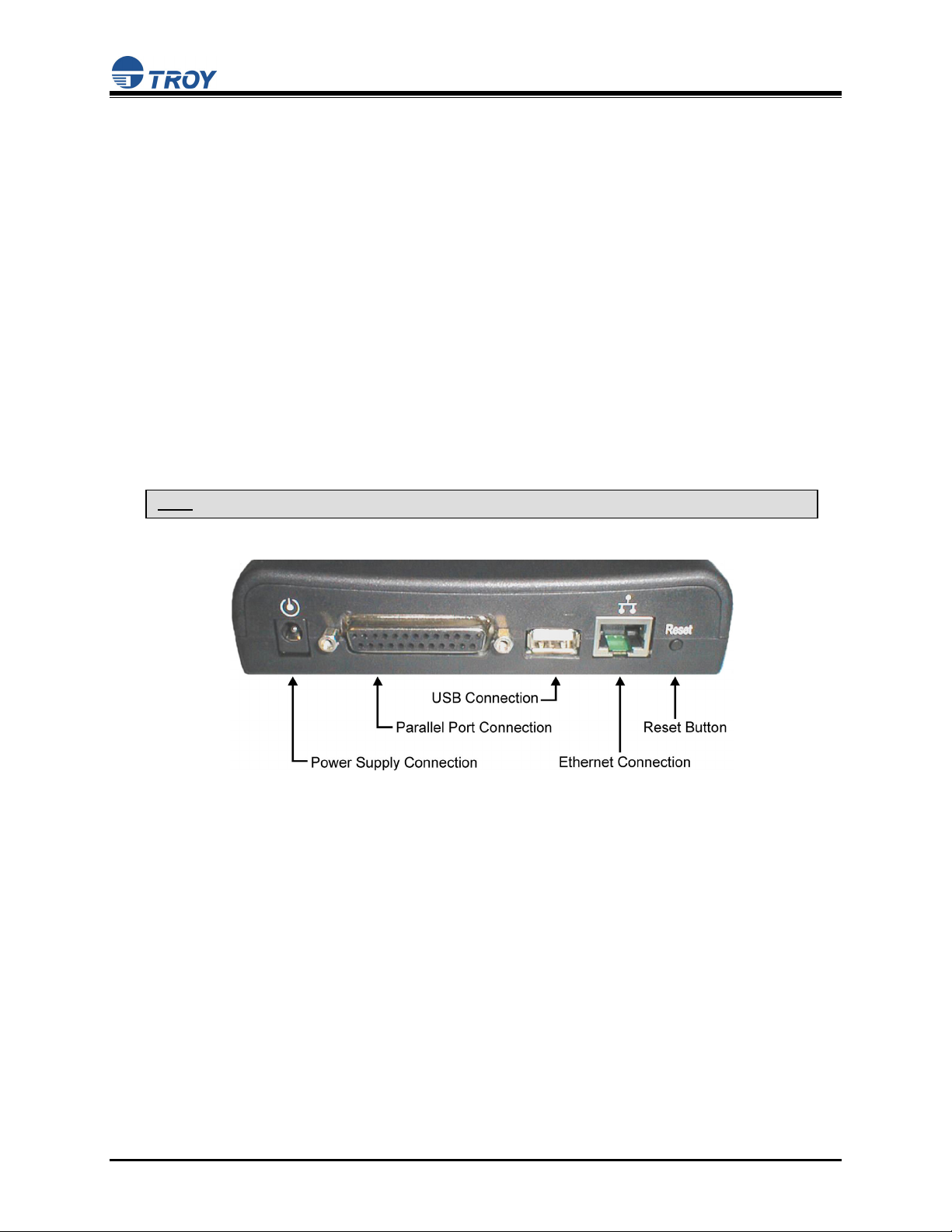
Print Server Components
The print server includes the following components. Detailed descriptions of these components are
provided below:
Power connector – The power supply cable plugs into this connector.
Test button – Pressing this button for less than three seconds will print a test page on the printer.
Pressing and holding this button for more than five seconds will reset the print server to factory
default settings.
LED status indicators – used to indicate the operational states of the print server. Refer to the LED
status light descriptions on the next page.
Ethernet Port – This port is used for connecting the print server to a 10/100Base-TX Ethernet card,
hub, router, or other wired access point for network access.
Parallel port – The parallel port is used for connecting the print server to the IEEE 1284-compliant
parallel port of your printer (parallel port models only).
USB port – The USB port is used for connecting the print server to the USB 2.0 port of your
printer. You must use a standard USB A (print server side) to B (printer side) cable (USB port
models only).
NOTE: A USB 2.0 cable must be used to take full advantage of the high-speed USB 2.0 connection.
Document #40181-120 Rev. A 1-4
Page 9
User’s Guide
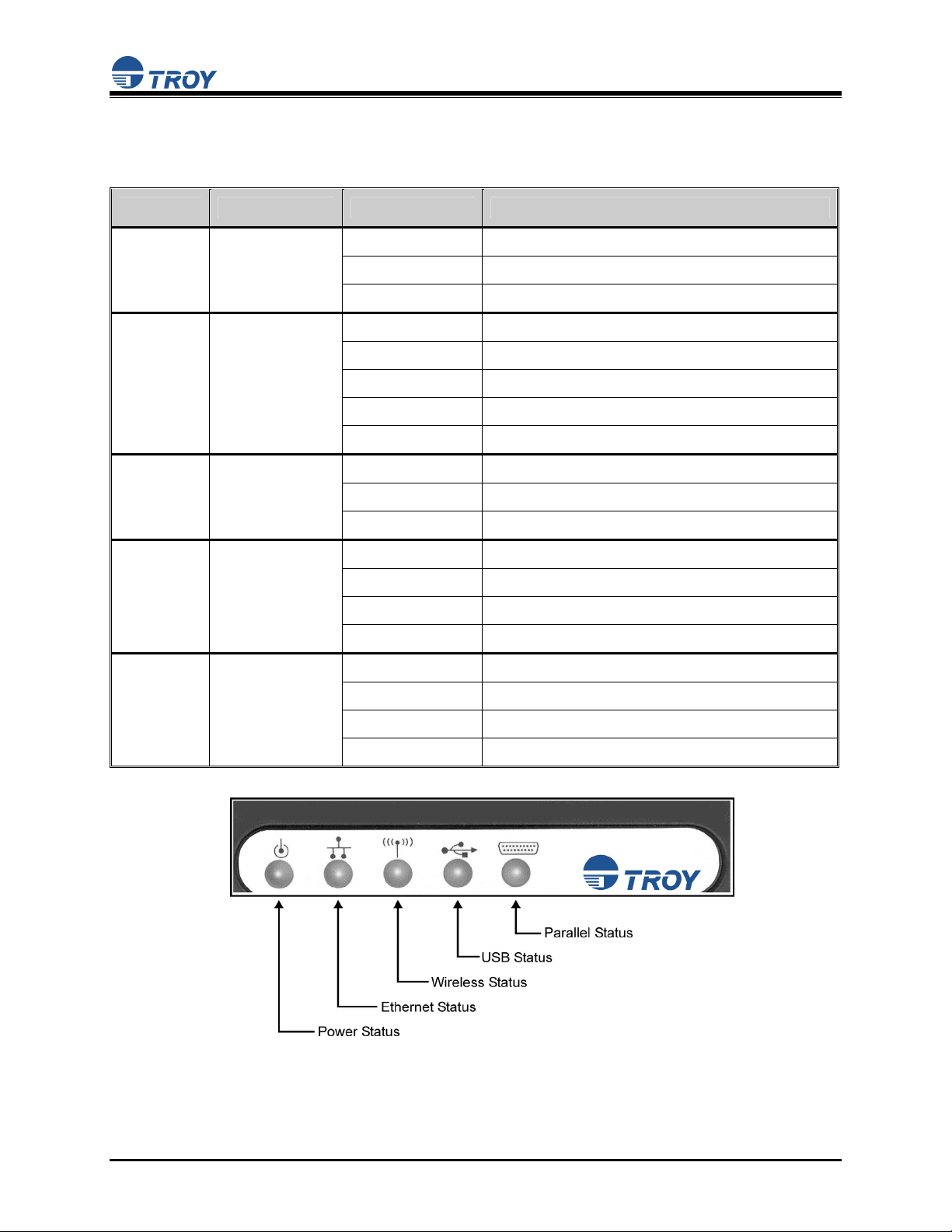
LED Indicators
The front edge of the print server provides five Green/Orange LEDs (Light Emitting Diode) indicators for
easy monitoring. The following table defines the function of each LED.
Label Color State Status
POWER GREEN
10/100 GREEN/ORANGE
WIRELESS GREEN
USB
(USB
PORT
MODELS
ONLY)
PARALLEL
REEN/ORANGE
G
REEN/ORANGE
G
OFF
Green ON
Green Blinking
OFF
Green ON
Green Blinking
Orange ON
Orange Blinking
OFF
Green ON
Green Blinking
OFF
Green ON
Green Blinking
Orange ON
OFF
The device is not receiving power
The device is ready
Device error
No Ethernet link
100baseTX link
100baseTX data
10baseT link
10baseT data
No wireless link
Wireless link
Wireless data
No printer attached
Printer ready
Printer data
Printer error
No device ID detected from printer
(
PARALLEL
PORT
MODELS
ONLY
)
Document #40181-120 Rev. A 1-5
Green ON
Green Blinking
Orange ON
Printer ready
Printer data
Printer error
Page 10

User’s Guide
Pushbutton Functions
The front edge of the print server provides a momentary pushbutton that can be used to print a
test/configuration page or reset the device to factory default settings.
Action Function
Press pushbutton for > 1/8 second but < 5
Prints a test/configuration page on each connected port
seconds
Press pushbutton for > 5 seconds Resets the device configuration to factory defaults. The
unit will reinitialize itself after updating the
configuration memory.
Factory Default Settings
The TROY200 Series Print Server is shipped with a default configuration. The settings can be changed to
suit specific installation requirements via the ExtendView Utility, or other SNMP-based utilities, the
embedded Web server, or via a Telnet connection to the Print Server’s internal console. The factory
default settings can be easily restored at any time by performing a cold reset (press and hold the
pushbutton on the device for more than five seconds).
Default Settings (wired and wireless print servers)
Parameter Setting
IP Address 190.0.0.192
TCP/IP Method AUTO (BootP and DHCP are enabled)
Password access
Wireless Default Settings (wireless print servers only)
Parameter Setting
Wireless Mode Ad-Hoc (peer-to-peer)
RF Channel 11
ESSID printer (lower case)
Document #40181-120 Rev. A 1-6
Page 11
y
User’s Guide
Section 2 – Hardware Installation
Before You Begin
Before installing the print server, make sure you have installed and set up your printer as described in the
documentation that came with the printer and that your printer functions properly. TROY200 Series Print
Servers support a parallel and/or USB connection to your printer.
Hardware Installation (wired and wireless versions)
NOTE: Be sure to review the hardware requirements in the previous section to ensure you have the necessar
information before installing the print server.
1. Write down the 12-digit MAC address printed on the label located on the bottom of the print server
(for example: 004017023F96). You may need this number in order to configure the print server.
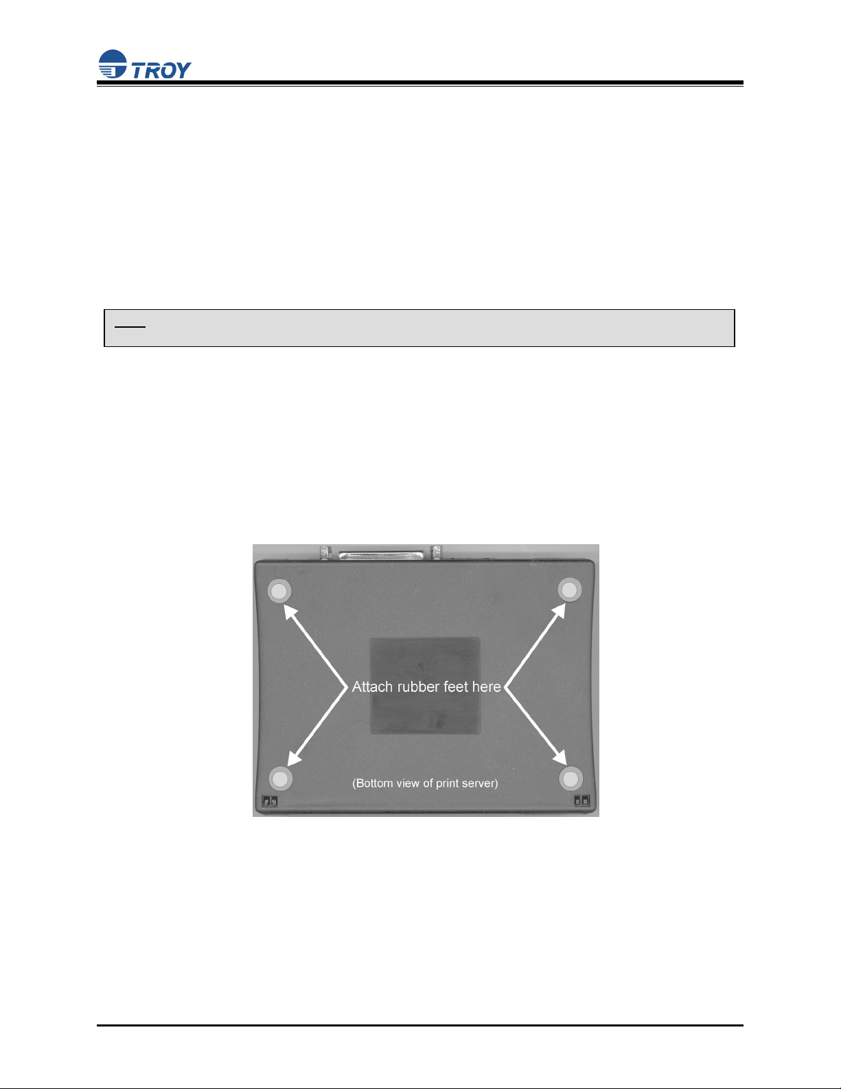
2. Mount the print server on either the printer or the desktop:
Printer mount – attach the print server to a suitable location on the side or rear of your printer by
applying an adhesive Velcro strip (provided in the printer mounting kit) to your printer and at the
top of the print server as it is to be attached to your printer.
Desktop mount – attach the adhesive rubber feet (provided in the desktop mounting kit) to the
bottom of the print server as shown below.
Document #40181-120 Rev. A 2-1
Page 12

User’s Guide
3. Connect the print server to your printer(s) using the USB and/or parallel port of your printer. For a
USB connection, use a standard USB A (print server side) to B (printer side) cable. For a parallel
connection, use an IEEE 1284-compliant parallel printer cable.
4. Plug the print server power supply adapter into a suitable AC receptacle, and then plug the power
supply cable into the print server. The print server will run through a sequence of power-up
diagnostics for a few seconds.
If the print server is operating properly, the power LED will illuminate continuously (refer to
page 1-5 for detailed LED status descriptions).
If the power LED blinks continuously in a regular pattern, a problem exists. If this is the case, try
powering the print server OFF and then ON again.
If the problem persists, refer to the Troubleshooting section in this User’s Guide.
5. Connect the print server to y our network through a switch or hub using a category 5 (CAT5) Ethernet
cable. The print server’s IP address must be configured before a network connection is available. If
your network offers DHCP (Dynamic Host Configuration Protocol), the print server will
automatically search for a DCHP server upon power up and obtain an IP address. If your network
does not offer DHCP, a static (fixed) IP address must be assigned (see your system administrator for
assistance). In most cases, a fixed IP address is preferred because a DHCP server may not always
assign the same IP address to the print server when the print server is powered ON.
NOTE: The IP address must be within a valid range, unique to your network, and in the same subnet as your PC.
NOTE: For wireless print servers, if a wired connection is established to the unit, the wireless link will be disabled.
Document #40181-120 Rev. A 2-2
Page 13

User’s Guide
Verifying the Connection to the Printer
NOTE: Before attempting to print, it is very important to verify the connection between the print server and printer.
If this connection is not working, you will not be able to print!
1. Verify that both the print server and the printer are powered on and ready, and that a USB or parallel
printer cable is properly connected between the print server and printer.
2. Print a test page by pressing the Test button once. If the connection is good, a test page will print on
the printer. If nothing prints out, make sure that the printer cable is properly connected, your printer
is on line, and that no error conditions exist with the printer (off line, paper jam, out of toner, etc.).
NOTE: The test page will only work with printers that can directly print PCL, PostScript, or text. It will not w ork with
some "Windows" printers like the HP DeskJet 820 (which performs the image rasterization in the PC), nor w ill it work
with HP-GL/2 or RTL plotters (unless the PostScript option is installed). For such devices, you must print a job from
an appropriate application program in order to test the print server-to-printer connection.
If none of the above suggestions work, refer to the troubleshooting section in this User’s Guide, or contact
TROY Technical Support at (800) 332-6427, 8:00 AM to 8:00 PM, Eastern Standard Time; or visit the
TROY web site at
assistance. Customers located outside the United States, please call (304) 232-0899. European
customers, please call +49 (0) 7032-9454-21, or send an e-mail to
http://www.troygroup.com, or send an e-mail to technicalsupport@troygroup.com for
support@troygroup.de for assistance.
Document #40181-120 Rev. A 2-3
Page 14

User’s Guide
Section 3 – Configuration and Management
Configuration Options
TROY200 Series Print Servers (wired and wireless models) can be configured using a variety of options,
some of which do not require any software installation on the host PC. The print server can be configured
and managed via an Ethernet or wireless connection using the ExtendView Utility (recommended), the
embedded web (HTTP) server pages, or the print server’s internal configuration console, which can be
accessed via a Telnet connection. If you choose to use the TROY ExtendView Utility (provided on the
TROY200 Series Print Server Installation CD), the software must be installed prior to use. Additional
options for print server configuration and management are available as third-party utilities that can be
downloaded from their respective web sites. If you are using a wireless print server, you can still
configure it via an Ethernet connection or optionally configure it via a wireless connection.
ExtendView Utility
used for advanced print server configuration, and allows you to configure for TCP/IP, Netware,
AppleTalk, and the wireless settings (for wireless print server models only).
uses a 32-bit graphical user interface.
works with Windows PCs running the TCP/IP protocol.
included on the TROY200 Series Print Server installation CD.
can be downloaded from the TROY web sites:
USA
: http://www.troygroup.com
Europe
after installation, this utility can be run from the START menu.
INSTALLING THE EXTENDVIEW UTILITY (WINDOWS OPERATING SYSTEMS):
1. Ensure your PC is connected and has access to your network.
: http://www.troy group.de
2. Connect an available Ethernet cable from your network hub to the print server. Ensure the print
server is powered on.
3. Insert the CD supplied with your print server into the CD-ROM drive of your computer. The CD
should automatically start and display a menu screen. Click on Install Software.
4. Select TCP/IP Management Utilities, and then click on Next.
5. Select ExtendView, and then click on Install.
Web Browser Interface
allows you to configure the print server with a standard web browser (e.g., Internet Explorer or
Mozilla).
no additional software is needed on the system.
can be used on any system that supports web browser capabilities.
type the IP address into your web browser address bar to connect.
the default password is ACCESS (all uppercase characters).
Document #40181-120 Rev. A 3-1
Page 15

User’s Guide
HP Web JetAdmin Utility
a web browser-based HP utility (e.g., Internet Explorer or Mozilla).
can be downloaded from the HP web site http://www.hp.com
.
Configuration Console
a command-line-oriented console.
contains advanced features not available through ExtendView or the Web Browser Interface.
the default password is ACCESS.
can be accessed via TELNET using the print server’s Ethernet connection.
type HELP for a list of console commands.
NOTE: When connected, press ENTER to get the “#” prompt, enter the password ACCESS (will not ‘ECHO’ on your
screen), and press ENTER to get a “Local>” prompt (no response required for the “Enter Username>” prompt).
When the “Local>” prompt appears, the console is ready to accept commands.
Document #40181-120 Rev. A 3-2
Page 16

r
User’s Guide
Configuring the Print Server via an Ethernet Connection
For Microsoft Windows operating systems, the TROY ExtendView Utility (provided on the TROY200
Series Print Server Installation CD) is the recommended method of configuring one or more print
servers on your network. Once the print server obtains an IP address (occurs automatically when the unit
is powered ON and connected to a DHCP network), the ExtendView Utility’s auto-discovery feature will
search for and locate all print servers on the network and then display the IP address for each discovered
print server. For non-Windows operating systems such as Macintosh or Unix systems, a standard web
browser (e.g., Microsoft Internet Explorer or Mozilla) can be used to access the configuration settings of
the print server (refer to the next page, “Using the Web Browser Interface” instructions). No additional
software is required.
USING THE EXTENDVIEW UTILITY TO CONFIGURE THE PRINT SEVER (WINDOWS OPERATING SYSTEMS):
1. Start the ExtendView Utility by clicking on Start, Programs, TROY Group, and then ExtendView.
2. When the Welcome screen appears, click on Next, choose any name for your View Name, select
Automatically create a view with default settings, and then click on Finish.
3. Double-click on the print server that you want to use from the list. The default print server name is
TWC_xxxxxx (where xxxxxx is the last six digits of the MAC address from the label located on the
back of the print server).
4. If you are using TCP/IP (recommended for Windows) and you do not have a DHCP server (see note
below), you will need to manually assign a valid IP Address (if you are not sure what IP address is
valid, ask your network administrator), and then click on OK.
5. Configure the 802.11a, 802.11b, or 802.11g wireless settings (wireless print servers only). To operate
on a wireless network, you must select your country or region from the drop-down list. This field
designates the region of operation for which the wireless interface is intended. It may not be legal to
operate the print server in a country/region other than the country/region shown in the drop-down list.
You must also set the wireless mode (ad-hoc or infrastructure), SSID channel, and WEP encryption of
the wireless print server to the same configuration as the wireless network you want the print server to
communicate on. All nodes of a wireless network need to have the same settings in order to
communicate with each other.
wireless mode (ad-hoc or infrastructure)
SSID channel
wireless security settings
NOTE: It may not be legal to operate the print server in a country or region other than the country or region shown in
the drop-down list. If your country or region is not listed, please check with your local government agency.
NOTE: Refer to the wireless security supplement (provided in print with the wireless print server and is also
available from the TROY web site at http://www.troygroup.com/Support/Connectivity/Documentation/index.asp
extra wireless security configuration instructions.
NOTE: If you are using DHCP on your network, the print server should have acquired valid IP settings at this point
and no further configuration is necessary. However, for most installations, a static IP address is preferred. If your
DHCP server does not allow the print server to keep its assigned IP address permanently, then you must manually
assign an IP address. In this case, use a static IP address outside the range reserved for DHCP (see your DHCP
server documentation for details). To assign a static IP address, right-click on the print server in the menu, and then
select Configuration. On the TCP/IP tab, under IP Address Resolution, select Set Permanent, and assign a valid
static IP address for your network. Click on OK to save the new settings.
) fo
Document #40181-120 Rev. A 3-3
Page 17

r
User’s Guide
USING THE WEB BROWSER INTERFACE TO CONFIGURE THE PRINT SERVER (NON-WINDOWS SYSTEMS):
To configure the print server using non-Windows operating systems (e.g., Unix systems), a standard web
browser (e.g., Microsoft Internet Explorer or Netscape Navigator) can be used to access the print server’s
embedded Web (HTTP) server pages, which contain the print server’s configuration options. No
additional software is required.
1. Ensure your PC is connected and has access to your network.
2. Connect an available Ethernet cable from your network hub to the print server. Ensure the print
server is powered ON.
3. With your printer and print server switched on and ready, press the test button on the print server to
print a test page. The test page will display the current IP address assigned to the print server by your
network DHCP service. If your network does not use DHCP, then the print server will have the
default IP address of 192.0.0.192. In any case, your computer must use an IP address other than the
one used by the print server in order to establish a connection between the two devices.
4. Configure the 802.11a, 802.11b, or 802.11g wireless settings (wireless print servers only). To operate
on a wireless network, you must select your country or region from the drop-down list. This field
designates the region of operation for which the wireless interface is intended. It may not be legal to
operate the print server in a country/region other than the country/region shown in the drop-down list.
You must also set the wireless mode (ad-hoc or infrastructure), SSID channel, and WEP encryption of
the wireless print server to the same configuration as the wireless network you want the print server to
communicate on. All nodes of a wireless network need to have the same settings in order to
communicate with each other.
5. From the host computer, open a standard web browser (e.g., Microsoft Internet Explorer or Netscape
Navigator), enter the IP address of the print server into the address bar of the web browser, and then
press Enter. The Web Browser Utility will be displayed, allowing you to configure the print server.
The menu selections are displayed on the left side of the screen, and the individual settings are
located at the top of the screen (see example below). Use the browser’s Forward and Back buttons to
navigate to the sub pages where you can configure the print server’s settings.
NOTE: It may not be legal to operate the print server in a country or region other than the country or region shown in
the drop-down list in ExtendView. If your country or region is not listed, check with your local government agency.
NOTE: Refer to the wireless security supplement (provided in print with the wireless print server and is also
available from the TROY web site at http://www.troygroup.com/Support/Connectivity/Documentation/index.asp
extra wireless security configuration instructions.
Document #40181-120 Rev. A 3-4
) fo
Page 18

r
User’s Guide
USING A THE INTERNAL COMMAND CONSOLE TO CONFIGURE THE PRINT SERVER:
The command console can be accessed using a Telnet connection via an Ethernet connection. To use a
Telnet connection, follow these steps:
1. Ensure the print server is connected via an Ethernet cable to the host computer.
2. From the Windows Start menu, click on Run, and then type the following command (where
x.x.x.x. is the IP address of the print server.
After a connection is established, press RETURN or ENTER to get the ‘#’ prompt, enter the
password ACCESS (it will not ‘echo’ on your screen), and type anything in response to the Enter
Username> prompt. When you get the Local> prompt, you are ready to enter commands. Type Help
for a list of console commands.
telnet X.X.X.X
First-Time Configuration of the Wireless Print Server Using 802.11b or
802.11g
It is recommended that you initially configure the print server via a wired connection. However, if you
choose to configure the wireless print server for the first time from a computer via an 802.11b or 802.11g
wireless connection, you will need to temporarily change the settings on your computer to match the
default settings of the print server as follows:
Wireless Mode: Ad-Hoc (sometimes referred to as Peer-to-Peer)
Channel: 11
SSID (or wireless network name): printer
NOTE: It is not necessary to change your computer’s settings if you are configuring the print server’s settings via an
Ethernet connection. The 802.11a wireless protocol cannot be used for this method of configuration.
You should now be able to configure your print server using either the ExtendView Utility or the Web
Browser Configuration as described in the previous sections.
(wireless print servers only)
NOTE: Be sure to set your PC back to its original wireless settings after you finish configuring the wireless print
server.
NOTE: Refer to the wireless security supplement (provided in print with the wireless print server and is also
available from the TROY web site at http://www.troygroup.com/Support/Connectivity/Documentation/index.asp
wireless security configuration instructions.
fo
Document #40181-120 Rev. A 3-5
Page 19

User’s Guide
Windows Print Queue Configuration
TROY recommends using the ExtendNet Connect for TCP/IP software for Windows printer port
configuration (provided on the TROY200 Series Print Server Installation CD). TROY200 Series Print
Servers are also compatible with Windows standard TCP/IP port and LPR ports. If you are using the
Windows standard TCP/IP port, the default port number is 9100. Perform the following steps to install
and use ExtendNet Connect for TCP/IP:
1. Install the ExtendConnect IP Port Monitor by inserting the CD supplied with your print server and
clicking on Install Software.
2. Select ExtendNet Connect Windows Printing, click on Next, click on ExtendNet Connect for
TCP/IP, and then click on Install. Follow the on-screen instructions to complete this installation.
3. Install the printer driver software according to the documentation for the printer.
4. Click the Windows Start button, select Settings, and then Printers (Start, then Printers and Faxes if
you are using Windows XP).
5. Right-click on the printer you wish to associate with the network port, and then select Properties.
6. If you are using Windows NT/2000/XP/2003, go to the Ports tab. If you are using Windows
95/98/ME, go to the Details tab, and then click on Add Port.
7. If you are using Windows NT/2000/XP/2003, highlight TROY Wireless ExtendNet Connect IP
Monitor, and then click on New Port.
8. If you are running Windows 95/98/ME, select Other, highlight TROY Wireless ExtendNet Connect
IP Monitor, and then click on OK. The search will begin for available print servers.
9. Highlight the print server you would like to create the port for, and then click on ADD.
10. Make sure the port you created is chosen, and then click on Apply. You are now ready to print.
Document #40181-120 Rev. A 3-6
Page 20

User’s Guide
Macintosh Print Queue Configuration
TROY200 Series Print Servers support the AppleTalk protocol running over Ethernet (also known as
EtherTalk). This capability allows Macintosh computers to print jobs to a printer simultaneously with
jobs from Windows, UNIX, NetWare, and other computers.
NOTE: TROY200 Series Print Servers are also compatible with the Macintosh TCP/IP Printer option in the Print
Center as long as you have a valid IP Address configured (refer to the section “Configuring your print server”).
Enter the IP Address of the print server for the “Printer’s Address”, and make sure the “Use default queue on
server” option is checked, and select your correct “Printer Model”.
TROY print server AppleTalk capabilities allow a printer to appear as a shareable printer node on an
AppleTalk Phase 2 network. The TROY print server broadcasts information to Macintoshes on the
network, and automatically appears in the Print Center or Chooser of each Macintosh. Application
programs (such as Microsoft Word, Excel, PageMaker, etc.) can print without modification or special
software on the Macintosh.
MACINTOSH CONFIGURATION (OS 8.X AND 9.X):
Identify the printer to which the print server is connected, and install the printer driver.
1. Verify that Ethernet is enabled from the Network Control Panel or AppleTalk Control Panel.
2. At a Macintosh workstation, from the Apple menu, open the Chooser.
3. If the Chooser window displays an AppleTalk zone list, select the necessary zone. Click on the icon
for the printer driver you are going to use. If you have a Postscript printer, you can use the
LaserWriter driver.
4. Select the print server name (the default is TWC_xxxxxx_P1_AT, where "xxxxxx" are the last six
digits of the Ethernet address.).
5. Close the Chooser. You can now print to the printer using any standard Macintosh application
program.
Document #40181-120 Rev. A 3-7
Page 21

f
User’s Guide
MACINTOSH CONFIGURATION (OS 10.X)
1. If you have not done so already, set the name of your computer by going to the Applications folder*,
selecting System Preferences, and then Sharing. Type in the computer name in the Network Identity
section (you can also set the IP address here if you want).
2. Turn on Ethernet and AppleTalk by clicking on the Applications folder and clicking on Network.
Next to Configure: select Built-in Ethernet (you can leave the Location: setting as Automatic).
3. Click on the AppleTalk tab; ensure the box next to Make AppleTalk Active is checked. If necessary,
select the appropriate AppleTalk Zone (you can leave the Configure: setting as Automatic).
4. Now go to the Applications folder, open the Utilities folder, and select Print Center. The Printer List
will appear (it will be empty if you have no printers configured). Click on Add Printer..., and then
select AppleTalk instead of Directory Services.
5. All of the available AppleTalk printers on the network should appear. Click on the one you wish to
add, and then click Add. The printer will now appear in the Printer List.
6. To print from an application program, go to File and then Print, select the desired printer, and then
click on Print.
*NOTE: The Applications folder can generally be reached by double-clicking on the Macintosh HD icon on the desktop.
NOTE: TROY print servers are also compatible with the Macintosh TCP/IP Printer option in the Print Center as long as
you have a valid IP Address configured (refer to the section “Configuring your print server”). Enter the IP Address o
the print server for the “Printer’s Address”, and make sure the “Use default queue on server” option is checked, and
select your correct “Printer Model”.
Configuring to Print Using TCP/IP (OS 10.x)
1. From the System Dock, click on the Print Center icon, and then click on Add.
2. Select IP Printing and enter the IP address of the device. Make sure that Use Default Queue on
Server option is checked.
3. Select the appropriate Printer model, and then click on Add. The printer is now ready to accept jobs.
Document #40181-120 Rev. A 3-8
Page 22

User’s Guide
Section 4 – Troubleshooting
Introduction
This section describes procedures for troubleshooting problems you may encounter with the TROY print
server, and is divided into the following sections:
Installation Problems
Intermittent Problems
Protocol-Specific Troubleshooting
If you have followed the steps in this section and you believe that you have a defective print server, then
please refer to Section 5 – Where to Get Help for information on returning defective products.
Printing Problems
If you cannot print to the TROY print server after you install it, check the following:
Make sure that the printer is powered on and is on-line, and that all cables are securely plugged in.
If the printer initializes successfully but you cannot print, the problem could be one of the following:
There is a problem with the interface between the print server and the printer.
There is a problem with the network connection or cabling.
There is a queue setup problem, a print server setup problem, or other protocol-related problem.
Checking the Interface between the Print Server and the Printer:
1. Ensure that the print server is securely plugged into the printer.
2. After the printer is powered ON, wait until the printer initializes, and then print a self-test page by
pushing the Test button on the back of the print server for approximately one second.
NOTE: Pushing the Test button for more than five seconds will restore the factory default configuration settings.
If the self-test does not print, then there is possibly a hardware problem. Double-check the
connections. If you still cannot print, then make sure that your printer is capable of printing text,
PCL or PostScript (the self-test will not work unless one of these is supported). The only way to
test such printers is to use an application program with the correct printer drivers.
The following are some examples of printers that do not support direct printing of text files:
Some Windows printers (usually low-end inkjet printers) perform all the image
rasterization in the printer driver, so the printer only understands a raw image file.
Many plotters only support HP-GL/2, RTL, or proprietary languages.
If you are getting distorted printouts, try printing using the generic/text printer driver.
Document #40181-120 Rev. A 4-1
Page 23

User’s Guide
If the self-test page prints successfully but you cannot print a job or you get distorted printouts, make sure
the printer is set for the correct Page Description Language. Most new printers support AUTO mode,
which means that they will automatically switch between PCL and PostScript. However, older printers
like the LaserJet II, LaserJet III, and LaserJet IIISi require that the printer be set to the desired language
through the printer control panel. Also, verify that you have set up the drivers correctly on the
workstation. Some printers, like the Epson Stylus, require special drivers and will not print if standard
PCL or PostScript drivers are used.
Checking the Network Connection and Cabling:
If the self-test page prints but you cannot print documents, first check the network connection and
cabling.
If the appropriate LEDs are not on, there is probably a bad 10baseT or 100baseTX cable, or the
hub port is bad. If possible, try a different cable and hub port, or try connecting a different device
to the cable.
If you are using a hub, verify that the hub port is good by trying the print server on a different
port.
If you have a bridge or router located between the TROY print server and the host computer,
make sure that the device is set up to allow the print server to send and receive data from the host.
For example, a bridge can be set up to only allow certain types of Ethernet addresses to pass
through (a process known as filtering); therefore, such a bridge must be configured to allow
TROY print server addresses. Likewise, a router can be set up to pass only certain protocols, so
be sure that the desired protocol can be passed through to the TROY print server. In the case of
routers, also make sure that the protocol is routable (LAT, NetBEUI, and DLC/LLC are not
routable).
If the job exists in the queue but does not print, ensure that you are not trying to print a text job to
a PostScript printer. If you have a printer that is capable of automatic language switching, ensure
that the printer is not forced into PostScript mode.
Make sure that you are not trying to perform an illegal operation, such as attempting to print a
legal-size form when the printer only supports 8.5" x 11" paper.
Troubleshooting Windows Problems
If you are having trouble printing with Windows, ensure you can ping the TROY print server using the
DOS command PING ipaddress, where ipaddress is the IP address of the TROY print server. If you
cannot ping the print server, you will not be able to print.
Document #40181-120 Rev. A 4-2
Page 24

User’s Guide
Troubleshooting Network Configuration Problems
If you are using TCP/IP, make sure that your computer and the print server are on the same IP
segment or can reach each other with a PING command from the host. The IP address you assign
to the print server must be on the same logical network as your host computers (e.g., if your
computer has an IP address of 192.189.207.3, the print server should have an IP of
192.189.207.x, where x is an integer between 1 and 254), or you must properly configure your
router address to work with the print server.
If your print server is set to Auto or DHCP for obtaining an IP address, it is possible that the print
server’s IP address can change. Either configure your DHCP server to give the print server a
permanent lease, or configure the print server to be on a STATIC address outside the scope of
DHCP addresses.
The problem may be the result of mismatched or duplicate IP addresses. Verify that the IP
address is correctly loaded into the TROY print server (via the self-test page or through the
remote console) and make sure that no other nodes on the network have this address (duplicate
addresses are the biggest cause of TCP/IP printing problems). If the address is not correct, then
verify that the loading procedure was properly executed.
Also verify that the host computer and the print server are either on the same subnet (for example,
if the print server has a subnet mask of 255.255.255.0, the host must have the same subnet mask)
or that the router is properly configured to pass data between the two devices.
If the wrong IP address is loaded, check your network for file servers that have DHCP, BOOTP,
or rarp enabled, and make sure that these file servers are not set up to load IP addresses into the
print server.
Document #40181-120 Rev. A 4-3
Page 25

User’s Guide
Troubleshooting Wireless Configuration Problems
Make sure your computer’s wireless adapter and/or access point is configured properly and note
the settings, paying special attention to the wireless mode, SSID or network name, WEP or
security, and IP address settings so you can configure your print server to the same wireless
settings.
Make sure the radio mode is configured properly for 802.11a or 802.11g if auto mode is not
connecting properly.
Make sure you have a good wireless signal from your PC and from the print server, that the print
server is within range (90 meters or 300 feet), and that it is away from metal objects and other
devices that generate radio signals (like Bluetooth, Cordless Phones, and Microwave ovens).
Make sure your computer is set to infrastructure mode if you are connecting through an access
point, or ad-hoc (802.11) if you are connecting to the print server without an access point. See
the documentation for your wireless adapter for details.
If you want to use WEP encryption or password protection for your wireless network, and your
wireless adapter or access point normally uses a password or passphrase instead of WEP, it
should allow you to enter 0x followed by a ten digit (for 40-bit or 64-bit WEP) or twenty-six digit
(for 128-bit WEP) key in hexadecimal format (0-9 or A-F).
If you are using ad-hoc (peer to peer) mode and are experiencing slow performance or are having
intermittent problems connecting, try changing the RF channel of your wireless network. Refer
to your wireless adapter and/or access point documentation for more information. It is
recommended that you change the RF channel to at least three channels lower or higher than any
other wireless networks within range. The RF channel can be changed via the ExtendView
Utility or the Web Browser Configuration Utility for the print server.
Document #40181-120 Rev. A 4-4
Page 26

User’s Guide
Section 5 – Where to Get Help
Obtaining Technical Assistance
TROY technical support is available to assist you with any questions concerning the setup, operation, or
maintenance of your TROY200 Series Print Server.
Worldwide Web Support
Located at http://www.troygroup.com/wireless, the TROY web site provides answers to many common
technical questions and also includes copies of product manuals and literature, as well as utilities and
firmware load images.
Technical Support
North and South America
If you need to talk to one of our Technical Support Specialists, our support line is open Monday through
Friday, 8 AM to 8 PM, Eastern Standard Time.
U.S. 48 contiguous States: (800) 332-6427
Canada, Alaska, Hawaii, and South America: +1-304-232-0899
E-Mail :
Europe
Technical support is available in either German or English from Monday through Thursday, 9 AM to 12
PM and 1 PM to 5 PM, and on Friday from 9 AM to 12 PM and 1 PM to 4 PM.
Phone: +49-7032-9454-21
E-Mail :
Web:
technicalsupport@troygroup.com
support@troygroup.de
http://www.troygroup.de
Document #40181-120 Rev. A 5-1
Page 27

User’s Guide
Returning Products
If you need to return a TROY product for any reason (failures, incorrect shipments, etc.), follow the steps
below:
1. Contact the TROY Technical Support group at (304) 232-0899 to request a Return Goods
Authorization (RGA) number (for North and South American customers), or call +49-7032-9454-21
(for European customers) and request a Return Material Authorization (RMA) number.
2. Be prepared with the serial number of the unit you are returning. You will be asked for the serial
number to verify warranty coverage.
Please record these serial numbers in the space provided below for future reference.
Print Server Model #: ________________________________
Print Server S/N: ____________________________________
Make sure that you write the RMA or RGA number on the outside of the shipping container you use to
return the product. Please ship the defective product(s) to the appropriate address below:
North and South America
TROY Group, Inc. TROY GmbH
RGA# _________ RMA# _________
3 Bryan Drive Schwarzwaldstr. 99
Wheeling, WV 26003 D-71083 Herrenberg,
: Europe:
Germany
Contacts
Corporate Headquarters
TROY Group, Inc.
2331 South Pullman Street
Santa Ana, CA 92705 USA
(949) 250-3280
Technical Support
North and South America
U.S. 48 contiguous States: (800) 332-6427
Canada, Alaska, Hawaii, and South America: +1-304-232-0899
E-Mail:
Europe
Phone: +49-7032-9454-21
E-Mail:
Web:
technicalsupport@troygroup.com
support@troygroup.de
http://www.troygroup.de
Document #40181-120 Rev. A 5-2
Page 28

User’s Guide
Appendix A – Safety and Regulatory Notices
Information for United States Users
This equipment has been tested and found to comply within the limits for a Class B digital device
pursuant to Part 15 of the FCC Rules. These limits are designed to provide reasonable protection against
harmful interference in a residential installation. This equipment generates, uses, and can radiate radio
frequency energy and, if not installed and used in accordance with the instructions, may cause harmful
interference to radio communications. However, there is no guarantee that interference will not occur in a
particular installation. If this equipment does cause harmful interference to radio and television reception,
which can be determined by turning the equipment off and on, the user is encouraged to try to correct the
interference by one or more of the following measures:
Reorient or relocate the receiving antenna.
Increase the separation between the equipment and receiver,
Connect the equipment into an outlet on a circuit different from that to which the receiver is
connected.
Consult the dealer or an experienced radio/TV technician for help.
The user is cautioned that changes and modifications made to the equipment without the approval of
manufacturer could void the user’s authority to operate this equipment.
Operation is subject to the following two conditions: (1) This device may not cause harmful interference,
and (2) this device must accept any interference received, including interference that may cause undesired
operation.
The radiated output power of the print server is far below the FCC radio frequency exposure limits.
Nevertheless, print server shall be used in such a manner that the potential for human contact during
normal operation is minimized.
To satisfy RF exposure requirements, this device and its antenna(s) must operate with a separation
distance of at least 20 centimeters from all persons and must not be co-located or operating in conjunction
with any other antenna or transmitter. End-users must be provided with specific operating instructions for
satisfying RF exposure compliance.
Document #40181-120 Rev. A A-1
Page 29

User’s Guide
Declaration of Conformity (FCC)
According to 47CFR, Part 2 and 15 for Class B Personal Computers and Peripherals; and/or CPU Boards
and Power Supplies used with Class B Personal Computers:
We: TROY GROUP, INC.
Located at: 2331 South Pullman Street
Santa Ana, CA USA
Declare under sole responsibility that the product identified herein, complies with 47CFR Part 2 and 15 of
the FCC rules as a Class B digital device FOR HOME OR OFFICE USE. Each product marketed, is
identical to the representative unit tested and found to be compliant with the standards. Records
maintained continue to reflect the equipment being produced can be expected to be within the variation
accepted, due to quantity production and testing on a statistical basis as required by 47CFR §2.909.
Operation is subject to the following two conditions: (1) this device may not cause harmful interference,
and (2) this device must accept any interference received, including interference that may cause undesired
operation.
Trade Name: TROY
Type of Product: Ethernet and Wireless 802.11a, 802.11b, and 802.11g-enabled print server
Model: TROY200 Series
TROY Group, Inc. hereby declares that the equipment specified above conforms to the above
requirements.
Standards used and met in the assessment:
EN55022: 1998 Class B; CFR Title 47, Part 15, Subpart B, Subpart C, and Subpart E.
Information for Canadian Users (IC notice)
The term “IC” before the radio certification number only signifies that Industry of Canada technical
specifications were met. Operation is subject to the following two conditions: (1) this device may not
cause interference, and (2) this device must accept any interference, including interference that may cause
undesired operation of the device.
This Class B digital apparatus meets all requirements of the Canadian Interference-Causing Equipment
Regulations.
To prevent radio interference to the licensed service, this device is intended to be operated indoors and
away from windows to provide maximum shielding. Equipment that is installed outdoors is subject to
licensing.
This device has been designed to operate with an antenna having a maximum gain of 5 dB. Antenna
having a higher gain is strictly prohibited per regulations of Industry Canada. The required antenna
impedance is 50 ohms.
To reduce potential radio interference to other users, the antenna type and its gain should be so chosen
than the equivalent isotropically radiated power (EIRP) is not more than the required for successful
communication.
Document #40181-120 Rev. A A-2
Page 30

User’s Guide
Information for European Users
The print server and its built-in 802.11a, 802.11b, and 802.11g wireless technology is in compliance with
the Class B Information Technology Equipment requirements and other relevant provisions of European
Directive 1999/5/EC. The limits for Class B equipment were derived for typical residential environments
to provide reasonable protection against interference with licensed communications devices. The internal
function is a radio device using the 2.4 GHz frequency band (2.400GHz – 2.4835GHz). It is intended for
wireless communication with other 802.11a, 802.11b, and 802.11g-enabled devices in an indoor
environment.
The use of 802.11a, 802.11b, and 802.11g wireless technology in certain countries may be restricted.
Before using 802.11x products, please confirm with the frequency management authority in the country
where you plan to use it. Many countries allow indoor use only. In Italy, general authorization is
required if used outside. In France, the use of certain channels is restricted outdoors. In some situations
or environments, the use of 802.11x wireless technology might be restricted by the proprietor of the
building or responsible representatives of the organization, for example, in airplanes, in hospitals or in
any other environment where the risk of interference with other devices or services is perceived or
identified as harmful.
If you are uncertain of the policy that applies to the use in a specific organization or environment, you are
encouraged to ask for authorization to use 802.11x wireless technology prior to switching it on. Consult
your physician or the manufacturer of personal medical devices (pacemakers, hearing aids, etc.) regarding
any restrictions on the use of 802.11x wireless technology.
TROY Group cannot be responsible for any failure to satisfy the protection requirements resulting from a
non-recommended modification of the product.
Declaration of Conformity (CE)
Manufacturer: TROY Group, Inc
2331 South Pullman Street
Santa Ana, California 92705 USA
Telephone: (949) 250-3280
Product: Ethernet and Wireless 802.11a, 802.11b, and 802.11g-enabled print server
Model No.: TROY200 Series
TROY Group, Inc. hereby declares that the above-referenced product, to which this declaration relates, in
is conformity with the provisions of:
Council Directives 1999/5/EC (March 9, 1999), Radio Equipment and Telecommunications Terminal
Equipment.
Standards used and met in the assessment:
ETSI EN 300-328-2 V1.4.1 (2003-04)
ETSI EN 301-489-1 V1.4.1 (2002-08)
ETSI EN 301-489-17 V1.2.1 (2002-08)
ETSI EN 301-893 V1.2.3 (2003-08)
EN 55024
The documents required by this Directive are maintained at the corporate headquarters of TROY Group,
Inc., 2331 South Pullman Street, Santa Ana, California, 92705, USA.
Document #40181-120 Rev. A A-3
Page 31

User’s Guide
Appendix B – Updating Firmware
Loading New Firmware (Using the TCP/IP Update Utility)
The TROY print server’s internal firmware can be easily updated as updates become available from
TROY. Please visit the TROY web site for more information on how to download the latest firmware
updates at http://www.troygroup.com
defined configuration options.
. Updating the print server’s firmware will not change any user-
NOTE: The print server firmware can also be upgraded using the XAdmin32 Utility by downloading the software and
procedures from the TROY web site at http://www.troygroup.com
.
1. Run the TROY Wireless Update utility for TCP/IP. The About Update for TCP/IP window will be
displayed. Click on OK to continue. The Select Update File window will be displayed.
2. Select UpdateFiles (*.bin) file type, locate the print server bin file, and then click on Open. A
window will be displayed (see next page) showing the file(s) you have selected including the revision
level and date code for each file.
Document #40181-120 Rev. A B-1
Page 32

User’s Guide
3. Verify that the file(s) are correct, and then click on OK. The utility will start searching for qualified
print servers present on the network.
4. When the search process is complete, click on OK to continue. A list of discovered devices will be
displayed.
Document #40181-120 Rev. A B-2
Page 33

User’s Guide
5. Select the desired print server to be upgraded, click on the green icon, or click on UPDATE Æ
START. The firmware update process will begin automatically as soon as the print server is ready.
6. When the print server is ready , the firmware upgrade will begin. The IP address of the print server as
well as the file you are loading will be displayed.
Document #40181-120 Rev. A B-3
Page 34

User’s Guide
7. The update log will be displayed when the update process is finished. Click on Close to continue.
Loading New Firmware
NOTE: To upgrade your print server’s firmware from operating systems other than Windows or Macintosh, refer to
the Print server Administrator’s Guide (provided in PDF format on the TROY200 Series Print Server Installation CD).
1. If you are using the Macintosh OS-X operating system, download the firmware file to your desktop.
2. Go to the terminal command prompt and type cd desktop.
3. Type tftp <enter the IP address of the print server>, and then press Enter (e.g., tftp 192.168.0.4).
4. Type binary, and then press Enter.
5. At the tftp> prompt, type put <firmware file name> <password of the print server> (example: put
ppusb.bin access).
(Macintosh OS-X)
Document #40181-120 Rev. A B-4
 Loading...