

Page 1

Do-335
Specification:
Length: 2140mm(84.3")
Wing span: 2121mm(83.5")
Wing area: 76.1sq.dm(8.2sq.ft)
Wing loading: 144.5g/sq.dm(47.4oz/sq.ft)
Flying weight: 11kg(24.2lbs)
Radio: 6ch & 11servos(including 4 medium-size servos)
Or 6ch & 13servos(When assemble two engines)
Engine: 50cc gasoline (Factory’s recommendation)
Or one 1.20(frant) & one .91(rear)
SAFETY PRECAUTIONS
INSTRUCTION MANUAL
First-time builders should seek advice from people having building
experience.If misused or abused,it can cause serious bodily injury
and damage to property.
Fly only in open areas and preferably at a dedicated R/C flying site.
We suggest having a qualified instructor carefully inspect your
airplane before its first flight.Please carefully read and follow all
instructions included with this airplane,your radio control system
and any other components purchased separately.
(The people under 18 years old is forbidden from flying this model)
This R/C airplane is not a toy!
Page 2

: 50cc
6
(with 11 servos)
6
6
6 channel radio for aiplane is highly recommended for this model.
Warning
Remove the covering with proper
pressure to cut through only the covering itself.Otherwise,
cutting down into the balsa structure may weaken the
model part and cause accident.
The pre-covered film on ARF kits may wrinkle due to
variations of temperature.Smooth out as explained right.
Pre-cover the covering with clean cloth!
Start at low setting. Increase the setting if
necessary.If it is too high,you may damage
the film.
Iow setting
with cover(cloth)
4 inch Front spinner
4 inch Rear spinner
Powerer
We strongly recommend you use the thread lock for all the screws when you build your model.
Gasoline
1
(Option accessories)
3-way
pressure inlet
Air tank
3-way
pressure inlet
3-way
pressure inlet
3-way
pressure inlet
3-way
pressure inlet
Switch
Air inlet
Strut
Strut
Strut
Quick release connector
Make sure to assemble retracts as instructed below.
Three wheel retract system
Quick release connector
Pressure reduction inlet
Ø1.7mm
Ø0.2mm
Pleas notice the inner diameter
of eachside the pressure reduction inlet.
Please insure the sealing of theretract
system before flight .
The status when the
gear up
Pull out length of 8mm
to make gear down
Air valve
Air valve
3-way pressure inlet
5
1
Air tank
1
Air inlet
2
1
1
Air line (3000mm)
2
Quick release connector
Strut
( 90 )
1
Strut ( 110 )
Switch
Clevis
Rod (2X300mm)
1
1
1
Retainer
TP Screw(2.6x14mm)
2
Page 3

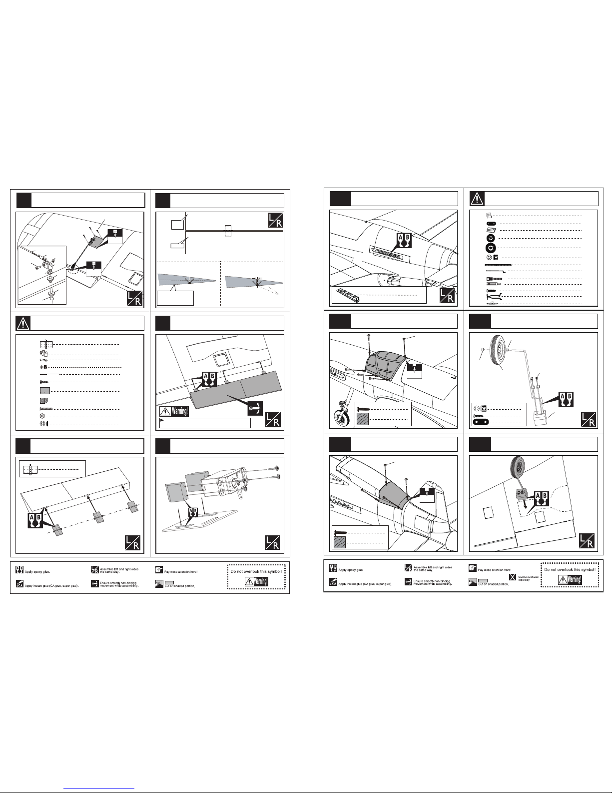
1mm
Aileron
Trailing
edge
Make sure they are in
the right position while
installing.
8
Pin hinge(24x24mm)
Securely glue together. If coming off during flights, you 'll
lose control of your airplane which leads to accidents!
Glue the pin hinges to the aileron with C A instant glue.
Keep some space about 1mm width between
the trailing edge and aileron.
Glue the aileron to the main wing with C A glue.
Make sure hinges are
mounted in the same line.
8
2
2
2
2
2
2
2
Clevis
Clevis
Rod (2.5x300mm)
TP Screw (2.3x12mm)
Wooden Block(20x20x8mm)
Servo tray(69x58x2mm)
Screw (4x45mm)
4
Washer(4x15mm)
Lock Nut (4mm )
2
Collar (3mm)
Rod (2.5x300mm)
Washer
Lock Nut (4mm )
Clevis
Clevis
Nut (3mm )
Collar (3mm)
Screw (3x10mm)
Screw (4x45mm)
2
2
Screw (4x45mm)
4
Washer(4x15mm)
Lock Nut (4mm )
2
Clevis
2
Clevis
2
2
Screw (3x10mm)
Nut (3mm )
2
Collar (3mm)
2
Rod (2.5x300mm)
8
Pin hinge(24x24mm)
Install the servo of the flap as the illusration below.
Install the nylon control horn and connect the linkage.
1
2
3
4
5
1
Accessory list for the coming installation steps.
Steel wire
Copper joiner
Aluminum tube
Clevis
Add a rubber ring to the
clevis for insuring safety
Collar (6mm)
Collar (6mm)
Collar (5mm)
Collar 6mm
3
Install the nose landing gear as below.
Wheel (90 mm)
Epoxy the nose landing gear to appropriate position
inside the fuselage.
AILERON
30mm
FLAP
20mm
20mm
Side View
Top view
Side View
Side View
25mm
25mm
RUDDER
Top view
Position for
right diagram.
ELEVATOR
Side View
20mm
20mm
151mm
Adjustment.
Adjustment.
Adjustment.
The centre of the Gravity.
FLAP
AILERON
106
107
108
109
20
105
110
Page 4
Securely glue together. If coming off during flights, you 'll
lose control of your airplane which leads to accidents!
6
Pin hinge
(36x20x1mm)
Flap
1mm
Make sure they are in
the right position while
installing.
Trailing
edge
Keep some space about 1mm width between
the trailing edge and flap.
Epoxy the flap to the mid wing.
TP Screw (2.3x12mm)
1.5mm
4mm
6
Pin hinge (36x20x1mm)
Install the servo of aileron as the illustation below.
Rod (2.5x300mm)
Clevis
Clevis
Lock Nut (3mm )
Screw (3x10mm)
Nut (3mm )
Screw (4x45mm)
Washer
Washer
8
2
2
2
2
2
2
2
Clevis
Clevis
Rod (2.5x300mm)
TP Screw (2.3x12mm)
Wooden Block(20x20x8mm)
Servo tray(69x58x2mm)
Screw (4x45mm)
4
Washer(4x15mm)
Lock Nut (4mm )
2
Collar (3mm)
Secure the servo,install the nylon control horn
and connect the linkage.
Epoxy the pin hinges to flap for the mid wing.
7
6
8
9
10
2
Accessory list for the coming installation steps.
Landing gear (6mm)
1
2
Copper joiner
Clevis
2
Collar (6mm)
7
2
Steel wire (0.5x1500mm)
1
Wheel (90 mm)
2
Wheel (115 mm)
TP Screw(3x20mm)
8
1
Landing gear (6mm)
1
Wooden Block(56x29x26mm)
Wooden Block(89x29x14mm)
1
Landing gear straps
4
2
Ally nose arm
Collar (6mm)
Wooden supporter
Collar (6mm)
TP Screw (3x20mm)
8
3x20mm TP Screw
Landing gear straps
4
Collar 6mm
4
Install the main landing gear and fix the
wooden supporter steadily.
Wheel (115 mm)
6
TP Screw (2.3x8mm)
Ply (15x15x3mm)
6
1.5mm
TP Screw (2.3x8mm)
Assemble the cover to the fuselage with TP
screw as illustration.
Epoxy the main landing gear to the wings.
8
TP Screw (2.3x8mm)
Ply (15x15x3mm)
8
1.5mm
TP Screw (2.3x8mm)
2
Pvc part
Epoxy the exhaust to the fuselage as illustration below.
Assemble the canopy to the fuselage with TP screws.
101
102
103
104
19
100
Accessory list for the coming installation steps.
All these parts below are for option .
Page 5

2
Main wing joiner(30x800mm)
Ply (15x15x3mm)
22
4
Wood dowel (6x50mm)
1
Rib template (2mm ply)
Bushing (8X4mm)
Nut (4mm)
6mm
Wheel (115mm)
Note:rubber wheels oleo struts
and retracts are optional.
2
Wheel (115 mm)
4
Plastic screw (6x50mm)
TP Screw (3x20mm)
8
Washer (3x6mm)
8
Rod (2.5x300mm)
Washer
Lock Nut (4mm )
Clevis
Clevis
Nut (3mm )
Collar (3mm)
Screw (3x10mm)
Screw (4x45mm)
2
2
Screw (4x45mm)
4
Washer(4x15mm)
Lock Nut (4mm )
2
Clevis
2
Clevis
2
2
Screw (3x10mm)
Nut (3mm )
2
Collar (3mm)
2
Rod (2.5x300mm)
Rod (2.5x300mm)
Clevis
Clevis
Lock Nut (3mm )
Screw (3x10mm)
Nut (3mm )
Screw (4x45mm)
Washer
Washer
Install the nylon control horn and connect the linkage.
Secure the servo,install the nylon control horn
and connect the linkage.
TP Screw (2.3x12mm)
1.5mm
4mm
Epoxy the wheel house to the wings carefully.
5mm
Cut away the surplus parts of plastic cover
carefully along the shaded line.
Note:Please fix the air tube before
assemble the wheel house to the wing.
3mm
Assemble the rear wheels to theh landing gears,epoxy the
gear pants to the landing gear and trim the surplus parts.
12
14
13
11
15
3
Accessory list for the coming installation steps.
176mm
15mm
80mm
1.8mm
TP Screw(3x20mm)
Washer (3x6mm)
4
4
Assemble the cowling to fuselage with screw.
According to the engine cut off the suplus part from the
former and glue it to the fuselage.as illustration..
Former
Cut away the surplus parts of the canopy
carefully along the shaded line.
2
Pvc part
Epoxy the cowl frame into the cowl steadily.
Epoxy the exhaust to the fuselage as illustration below.
Assemble the cowl to appropriate position in the fuselage
and trim the relevent position in the cowl and fuselage.
1
Former
1
Former
96
95
94
97
98
99
18
Page 6

TP Screw (3x20mm)
1.8mm
TP Screw (3x20mm)
8
Washer (3x6mm)
8
Washer (3x6mm)
A=A'
Make sure to glue securely.
If not properly glued, a failure in flight may occur.
Securely glue together.If coming off during flights,
you'll lose control of your airplane which leads
to accidents!
The sketch map when the main wing
assembled completely.
A`
A
According to the rib template drill holes in one wing and
epoxy wood dowel in them.
6mm
6mm
Wood dowel (6x50mm)
Rib template (2mm ply)
4
Wood dowel (6x50mm)
1
Rib template (2mm ply)
1
Main wing joiner(30x800mm)
Main wing joiner(30x800mm)
6mm
Rib template (2mm ply)
Plastic screw
Blind Nut
4
Plastic screw (6x50mm)
According to the rib template and drill holes to the fuselage.
Assemble the wing to the fuselage steadily and keep
the surface of model cleanly.
Fix the main wing to the fuselage with plastic screw.
Assemble the landing gear to the wheel house.
17
18
19
20
21
4
16
2mm
32mm
20mm
2mm
2mm
Push the hatch thimble to front when assemble
the canopy to fuselage.
3mm
3mm
20mm
145mm
15mm
32mm
110mm
2
Ply (15x15x6mm)
Ply (15x15x6mm)
1
Ply (15x15x6mm)
Collar(2mm)
Wooden Block
Screw
2mm
Epoxy the hatch thimble to appropriate position inside
to top hatch.
15mm
3mm
Screw (2x25mm)
1
1
1
2
1
Wooden Block (15x15x10mm)
Collar (2mm)
Thimble
4
Pvc part
4
Metal dowel (3X30mm)
Ply (15x15x3mm)
22
Metal dowel (3X30mm)
Metal dowel (3X30mm)
2
Ply (15x15x6mm)
1
Metal dowel (3X30mm)
Drill holes in the relevant position in the fuselage.
14
TP Screw (2.3x8mm)
fairing
TP Screw(3x20mm)
Washer (3x6mm)
4
4
1
Former
1
Former
Metal dowel (3X30mm)
Ply (15x15x3mm)
4
Ply (15x15x3mm)
Epoxy plies to appropriate position inside the top hatch
and drill holes in them.Epoxy metal dowel in them.
Epoxy plies to appropriate position inside the top hatch
and drill holes in them.Epoxy metal dowel in them.
89
90
91
92
93
17
Accessory list for the coming installation steps.
Page 7

Washer (4x8mm)
Washer (4x8mm)
Screw (4x35mm)
Washer (4x8mm)
Screw (4x25mm)
Nut (4mm)
Spring Washer (4mm)
4mm
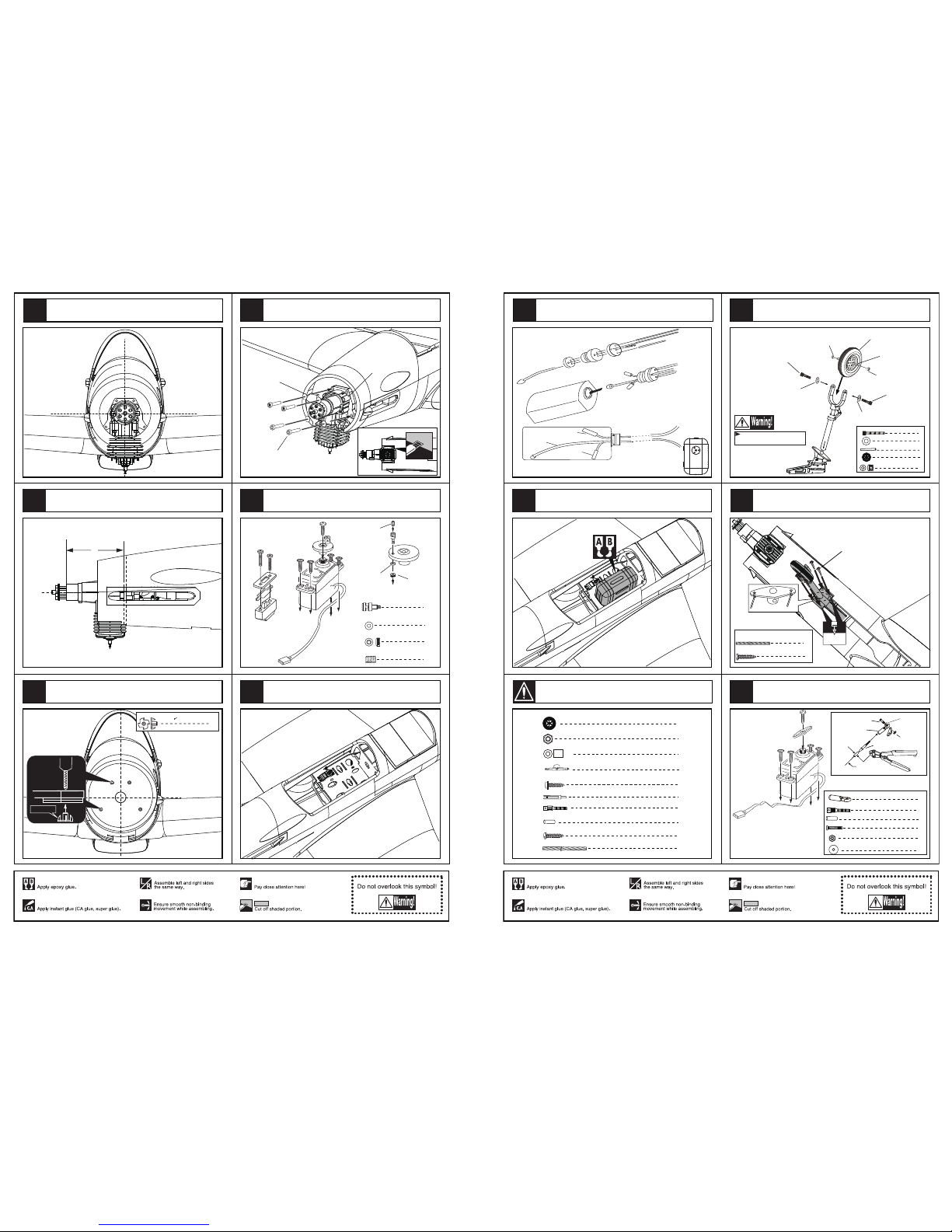
Assemble the engine.
Set Screw (3x4mm)
Set Screw (2mm)
Rod (2x500mm)
Set Screw (2mm)
Washer (2mm)
Linkage Stopper
1
1
1
1
1
4
4
Washer (4x8mm)
4
Rod (2x500mm)
Blind Nut (4mm)
Screw (4x25mm)
Set Screw (3x4mm)
Assemble the rear throttle linkage.
Mount the fuel tank into the fuselage.
Linkage Stopper
Washer (2mm)
Washer (2mm)
Nut (2mm)
Set screw (3x4mm)
Washer (2mm)
Set screw (3x4mm)
1
1
1
1
Assemble the servos and switch .
Fuel tank (550cc)
1
Connecting the rear engine and the rear throttle
servo via throttle linkage.
Assemble the switch servo to appropriate position
in the fuselage.
84
85
86
87
88
16
83
1
Stab Joiner(12x360mm)
1
Stab Joiner(12x300mm)
16
11
4
4
4
8
4
4
Clevis
Rod (2x300mm)
Retainer
TP Screw (2.3x12mm)
Wooden Block(10x13x8mm)
Servo tray(56x50x2mm)
Pin hinge(24x24mm)
Screw (3x40mm)
1
Rib template (2mm ply)
1mm
Elevator
Tailing
edge
Make sure they are in
the right position while
installing.
Keep some space about 1mm width between
the tailing edge and the elevator.
Glue the elevator to the stabilizer with CA glue.
Make sure hinges are
mounted in the same line.
6
Pin hinge(24x24mm)
Securely glue together. If coming off during flights, you 'll
lose control of your airplane which leads to accidents!
Clevis
Retainer
Rod (2x300mm)
Screw (2x10mm)
Install the servo of the elevator.
Install the nylon control horn and connect the linkage.
1
Rib template (2mm ply)
8
Wood dowel (4x30mm)
Glue the pin hinges to the elevate with CA glue.
23
24
25
26
5
Accessory list for the coming installation steps.
22
Page 8

1
Rib template (2mm ply)
Rib template (2mm ply)
TP Screw (2.3x12mm)
1.5mm
3mm
Rod (2x300mm)
Clevis
Washer(3x15mm)
Washer
Lock Nut (3mm )
Screw (3x40mm)
Screw (2x10mm)
Secure the servo in the stabilizer,install the control horn
and connect the linkage as illustration.
According to the rib template drill holes to
appropriate position in the fuselage.
According to the rib template drill holes to the stabilizer
root and epoxy the wood dowel in them.
Epoxy the stabilizer to the tail fuselage steadily.
4mm
4mm
4
Wood dowel (4x30mm)
Rib template (2mm ply)
Wood dowel (4x30mm)
Stab Joiner(12x360mm)
1
Rib template (2mm ply)
1
Stab Joiner(12x360mm)
Securely glue together. If coming off during flights, you 'll
lose control of your airplane which leads to accidents!
2
Pin hinge(24x24mm)
Make sure hinges are
mounted in the same line.
1mm
Upper rudder
Upper vertical fin
Make sure they are in
the right position while
installing.
Glue the pin hinges to the upper rudder with CA glue.
Keep some space about 1mm width between the
upper rudder and the upper vertical fin.
Assemble the accelerator push rod to the engine.
The sketch map when the engine install completion.
Install the servo of throttle.
Assemble the throttle servo in the fuselage.
Assemble the fuel tank as below.
Epoxy the fuel tank to the side fuselage.
28
29
30
31
32
6
27
Fuel supply line
Fuel spray line
Air pressure line
Mount the fuel tank into the fuselage.
Assembly of the fuel tank.
Fuel tank (550cc)
1
Assemble the switch servo to in the fuselage.
158mm
5 .2mm
Blind Nut
4
Blind Nut (4mm)
The side view of the engine install completion.
Drill four holes at the diameters as shown
for engine mount.
If you assemble a 120 engine in the nose,then you need
assemble a 91 engine in the rear.Please be kind to find
the front view of the 91 rear engine install completion.
78
79
80
81
15
77
82
Page 9

4
Blind Nut (4mm)
1
Engine mount (68x105mm)
Linkage Stopper
4
4
12
4
Washer(4x8mm)
Screw (4x35mm)
Spring Washer (4mm)
Nut (4mm)
2
4
Screw (4x25mm)
2
Plastic tube (2x500mm)
Fuel tank (550cc)
1
5 .2mm
Blind Nut
153mm
Washer (4x8mm)
Washer (4x8mm)
Screw (4x35mm)
Washer (4x8mm)
Screw (4x25mm)
Nut (4mm)
Spring Washer (4mm)
4mm
Assemble the engine.
The side view of the 120 engine install completion.
Drill four holes at the diameters as shown
for engine mount.
4
Blind Nut (4mm)
Set Screw (3x4mm)
Set Screw (2mm)
Rod (2x500mm)
Set Screw (2mm)
Washer (2mm)
Linkage Stopper
1
1
1
1
1
4
4
Washer (4x8mm)
4
Rod (2x650mm)
Blind Nut (4mm)
Screw (4x25mm)
Set Screw (3x4mm)
Assemble the throttle linkage.
Linkage Stopper
Washer (2mm)
Washer (2mm)
Nut (2mm)
Set screw (3x4mm)
Washer (2mm)
Set screw (3x4mm)
1
1
1
1
Assemble the servos and switch .
Connecting the engine and the throttle servo
via throttle linkage.
72
71
74
76
75
14
73
Accessory list for the coming installation steps.
Glue the upper rudder to the vertical fin steadily.
Securely glue together. If coming off during flights, you 'll
lose control of your airplane which leads to accidents!
Clevis
Retainer
Rod (2x300mm)
Screw (2x10mm)
Install the servos for the upper rudder in upper vertical fin.
Install the nylon control horn and connect the linkage.
TP Screw (2.3x12mm)
1.5mm
3mm
Rod (2x300mm)
Clevis
Washer(3x15mm)
Washer
Lock Nut (3mm )
Screw (3x40mm)
Screw (2x10mm)
4
Wood dowel (4x30mm)
Rib template (2mm ply)
4mm
1
Rib template (2mm ply)
1
Stab Joiner(12x300mm)
Stab Joiner(12x310mm)
4mm
Wood dowel (4x30mm)
Rib template (2mm ply)
Secure the servo in the upper vertical fin,install the
control horn and conncet the linkage as illustration.
According to the rib template drill holes to the
appropriate position in the fuselage.
According to the rib template drill holes to the appropriate
position in vertical fin root and epoxy the wood dowel in them.
34
33
35
36
37
38
7
Accessory list for the coming installation steps.
Page 10

Securely glue together. If coming off during flights, you 'll
lose control of your airplane which leads to accidents!
3
Pin hinge(24x24mm)
Make sure hinges are
mounted in the same line.
1mm
Bottom rudder
Bottom vertical fin
Make sure they are in
the right position while
installing.
Securely glue together. If coming off during flights, you 'll
lose control of your airplane which leads to accidents!
Clevis
Retainer
Rod (2x300mm)
Screw (2x10mm)
Install the servos for the bottom rudder in the
bottom vertical fin.
Install the nylon control horn and connect the linkage.
Epoxy the upper vertical fin to the fuselage steadily
as illustration.
Glue the pin hinges to the bottom rudder with CA glue.
Keep some space about 1mm width between the bottom
rudder and the bottom vertical fin.
Glue the bottom rudder to the bottom vertical fin steadily.
40
41
42
43
44
8
39
Washer (4x8mm)
Screw (4x25mm)
4
Washer(4x8mm)
4
Screw (4x25mm)
1.5mm
8
TP Screw (2.3x8mm)
Ply (15x15x3mm)
8
Fix the propeller shaft to the frame steadily as illustration.
Epoxy plies to relevant position inside the rear engine cover and
assemble the engine cover to the fuselage as illustration.
Open blades in the fiberglass spinner and epoxy it to the
spinner mount as illustration.
After assemble the wood spinner mount to the propeller
shaft,fix the propeller to the shaft with hex nut.
Nut (10mm)
wood spinner mount
1
1
1
Washer (10x20mm)
Fiberglass spinner
1
wood spinner mount
Not including
Washer (10x20mm)
Nut (10mm)
In case of 2-cycle & 4-cycle engine.
Customers can also use one front 120 engine and 90 rear
engine,please be kind to find the installation steps followed,
the front view of the 120 engine install completion.
8
Blind Nut (4mm)
2
Engine mount (68x105mm)
Linkage Stopper
8
8
24
8
Washer(4x8mm)
Screw (4x35mm)
Spring Washer (4mm)
Nut (4mm)
4
8
Screw (4x25mm)
4
Plastic tube (2x650mm)
Fuel tank (550cc)
2
177mm
104.5mm
91mm
To make sure the propeller
can circle freely.
67
66
68
69
70
13
Accessory list for the coming installation steps.
The accesories below will not included in our package.
Page 11

Assemble the nose linding gear servo to the fuselage.
Mount the receiver and the battery into the fuselage.
Assemble the servoe of rudder,switch in the fuselage.
4
Washer(4x8mm)
4
Screw (4x25mm)
8
TP Screw (2.3x8mm)
Ply (15x15x3mm)
8
Propeller shaft
Fiberglass spinner
Nut (10mm)
1
1
1
1
1
Washer (10x20mm)
5.2mm
Blind Nut
4
Blind Nut (4mm)
Propeller shaft
1
According to the center point in the frame for the rear engine and
the holes in the propeller shaft mark four dots in the frame.
According the four dots drill holes and set blind nut in them.
The side view when the propeller shaft install completion.
wood spinner mount
4
Blind Nut (4mm)
62
63
64
65
12
61
Accessory list for the coming installation steps.
4mm
Rib template (2mm ply)
1
Rib template (2mm ply)
4mm
Wood dowel (4x30mm)
2
Wood dowel (4x30mm)
Securely glue together. If coming off during flights, you 'll
lose control of your airplane which leads to accidents!
TP Screw (2.3x12mm)
1.5mm
3mm
Rod (2x300mm)
Clevis
Washer(3x15mm)
Washer
Lock Nut (3mm )
Screw (3x40mm)
Screw (2x10mm)
A=A'
B=B'
C=C'
The sketch map when the main wing
assembled completely.
A`
B`
B
A
Make sure to glue securely.
If not properly glued, a failure in flight may occur.
Temporarily fasten down the main wing and
check its correct position.
Securely glue together.If coming off during flihts,
you'll lose control of your airplane which leads
to accidents!
C C’
1
Linkage Stopper
4
12
Washer(5mm)
Spring Washer (5mm)
1
4
Screw (5mm)
Plastic tube (2x650mm)
Washer
4
4
Blind Nut (5mm)
Fuel tank (800cc)
1
(Not included)
(Not included)
(Not included)
(Not included)
Secure the servo in the bottom vertical fin,install the
control horn and conncet the linkage as illustration.
According to the rib template drill holes to the
appropriate position in the fuselage.
According to the rib template drill holes to the appropriate position
in bottom vertical fin root and epoxy the wood dowel in them.
Epoxy the bottom vertical fin to the fuselage
steadily as illustration.
46
45
48
47
49
9
Accessories list for the installation of using one 50cc
gasoline engine in the front(factory recommend).
Page 12
The front view when the 50cc engine install completion.
The side view when the 50cc engine install completion.
153mm
Drill four holes at the diameters as show
for engine mount.
6.2mm
Blind Nut
4
Blind Nut (5mm)
Linkage Stopper
Washer (2mm)
Washer (2mm)
Nut (2mm)
Set screw (3x4mm)
Washer (
2mm
)
Set screw (3x4mm)
1
1
1
1
Assemble the engine.
Assemble the servos and switch.
Screw (5mm)
Washer (5mm)
Washer
Assemble the throttle servo in the fuselage.
51
52
53
54
50
10
55
2
Steel wire (0.5x1500mm)
4
4
4
Clevis
Copper joiner
Aluminum tube(3x6mm)
TP Screw (2.6x14mm)
4
8
TP Screw (2.3x12mm)
1
Aluminum part(60x6mm)
1
Lock Nut (4mm )
1
Wheel (90 mm)
Note:rubber wheels oleo struts
and retracts are optional.
Bushing (8x6mm)
1
Brass collar (5mm)
Brass collar (5mm)
Wheel (90 mm)
Aluminum shaft
Screw (4x16mm)
Screw (4x16mm)
Washer(4x8mm)
Washer(4x8mm)
Collar (5mm)
2
1
Wheel (90 mm)
2
Washer(4x8mm)
2
Screw (4x16mm)
1
Aluminum shaft(5x50mm)
2
2
2
Clevis
Copper joiner
Aluminum tube(3x6mm)
2
2
Screw (2x10mm)
Nut (2mm )
2
Washer(2x5mm)
Steel wire
Copper joiner
Aluminum tube
Lock Nut (2mm )
Screw (2x10mm)
Ball joint
Washer(2x5mm)
Install the servo of nose landing gear.
Assemble the nose wheel.
1.5mm
TP Screw (3x20mm)
4
TP Screw (3x20mm)
2
Steel wire (0.5x1200mm)
Install the nose retract to appropriate position in the fuselage
and assemble the steeling fullarm around the landing gear
as illustration.
Fuel supply line
Fuel spray line
Air pressure line
Assembly of the fuel tank.
Mount the fuel tank to appropriate position in the fuselage.
57
58
60
59
11
56
Accessory list for the coming installation steps.
 Loading...