

Page 1
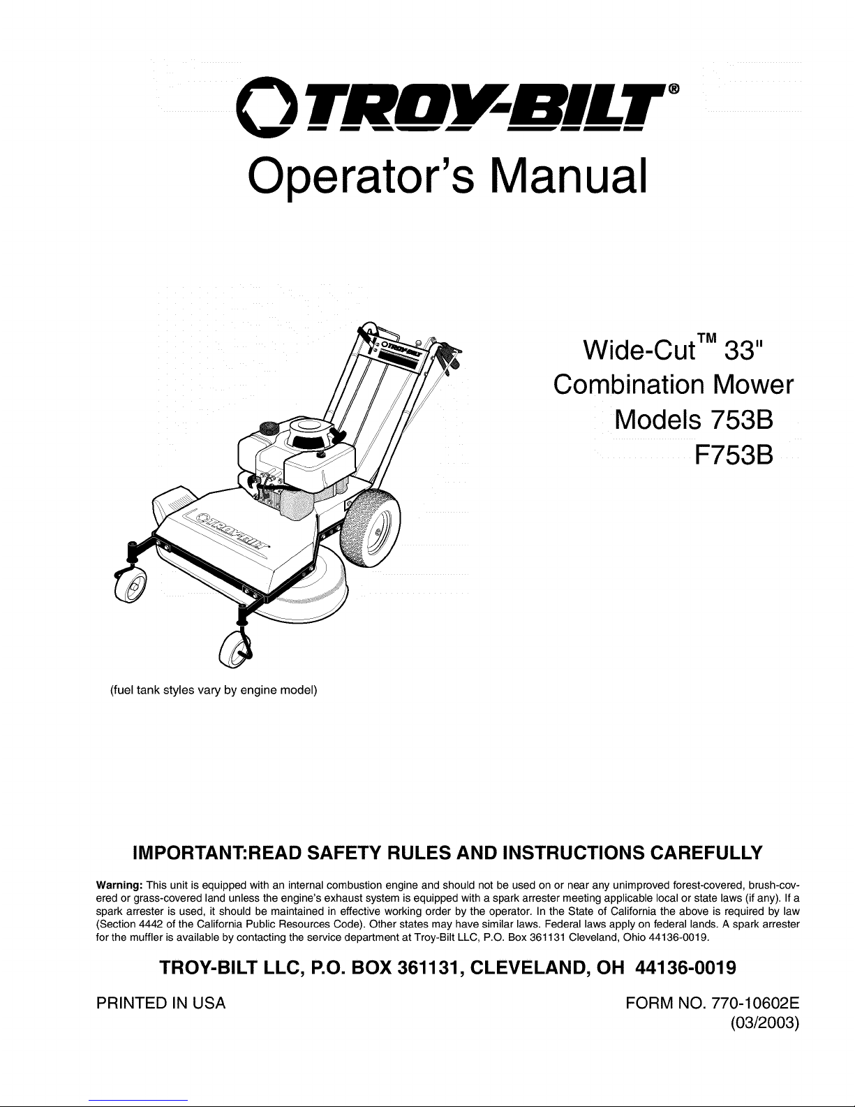
0 TRtII BILT --
Operator's Manual
Wide-CutTM 33"
Combination Mower
Models 753B
F753B
(fuel tank styles vary by engine model)
IMPORTANT:READ SAFETY RULES AND INSTRUCTIONS CAREFULLY
Warning: This unit is equipped with an internal combustion engine and should not be used on or near any unimproved forest-covered, brush-cov-
ered or grass-covered land unless the engine's exhaust system is equipped with a spark arrester meeting applicable local or state laws (if any). If a
spark arrester is used, it should be maintained in effective working order by the operator. In the State of California the above is required by law
(Section 4442 of the California Public Resources Code). Other states may have similar laws. Federal laws apply on federal lands. A spark arrester
for the muffler is available by contacting the service department at Troy-Bilt LLC, P.O. Box 361131 Cleveland, Ohio 44136-0019.
TROY-BILT LLC, P.O. BOX 361131, CLEVELAND, OH 44136-0019
PRINTED IN USA FORM NO. 770-10602E
(03/2003)
Page 2
TABLEOFCONTENTS
Content Page
Safety ................................................................... 1
Assembly................................................................. 4
Features and Controls....................................................... 8
Operation ................................................................ 11
Maintenance .............................................................. 16
Off-Season Storage ........................................................ 24
Lubrications............................................................... 25
Troubleshooting ........................................................... 27
Parts List................................................................. 28
Warrany Information........................................................ BackCover
FINDINGMODELNUMBER
This Operator's Manual is an important part of your new Wide-Cut TM mower. It will help you assemble, prepare and
maintain the unit for best performance. Please read and understand what it says.
Before you start assembling your new equipment, please locate the model plate on the equipment and copy the infor-
mation from it in the space provided below. This information is very important if you need help from our Customer
Support Department or an authorized dealer.
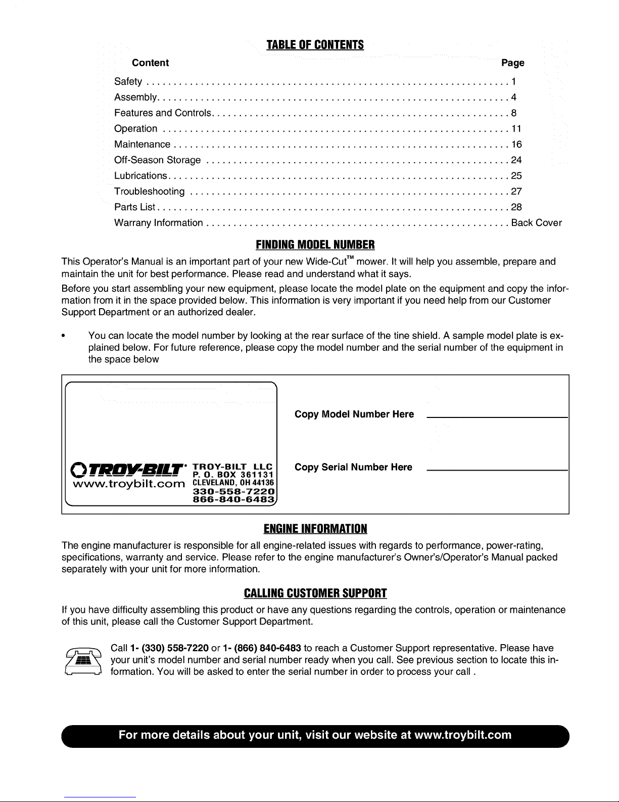
You can locate the model number by looking at the rear surface of the tine shield. A sample model plate is ex-
plained below. For future reference, please copy the model number and the serial number of the equipment in
the space below
OTRItV BILT. TROY-BILT LLC
P. 0. BOX 361131
www.troybilt.com CLEVELAND, 0H44136
330-558-7220
_. 866-840-6483_
Copy Model Number Here
Copy Serial Number Here
ENGINEINFORMATION
The engine manufacturer is responsible for all engine-related issues with regards to performance, power-rating,
specifications, warranty and service. Please refer to the engine manufacturer's Owner's/Operator's Manual packed
separately with your unit for more information.
CALLINGCUSTOMERSUPPORT
If you have difficulty assembling this product or have any questions regarding the controls, operation or maintenance
of this unit, please call the Customer Support Department.
Call 1- (330) 558-7220 or 1- (866) 840-6483 to reach a Customer Support representative. Please have
your unit's model number and serial number ready when you call. See previous section to locate this in-
formation. You will be asked to enter the serial number in order to process your call.
Page 3
Safety
WARNING:
The engine exhaust from this product contains
chemicals known to the State of California
to cause cancer, birth defects, or other reproduc-
tive harm.
SafetyAlertSymbol
_, his is a safety alert symbol. It is used in this
Owner's Manual to alert you to potential
hazards. Wheneveryou seethis symbol, readandobeythe
safety messagethat follows it. Failureto obey the safety
message could result in personal injury or property
damage.
IMPORTANT
Safe Operation Practicesfor Walk-Behind Mowers
This cutting machine is capable of amputating hands and feet and throwing objects. Failure to observe the
following safety instructionscould result in serious injury or death.
I. GENERALOPERATION
1.
.
Read,understand,andfollow all in-
structionson the machineandin the
manuals.Bethoroughlyfamiliar with
thecontrols andthe proper useof
themower beforestarting.
Donot put handsorfeet nearor
under rotatingparts. Keepclear of
themower bladeand discharge
openingatall times.
3. Onlyallow responsibleindividuals,
whoarefamiliar with the instruc-
tions,to operatethe mower.
4. Clearthe areaof objectssuch as
rocks,toys, wire, bones,sticks, etc.,
which could be pickedupand
thrown by the blade.
.
5. Besurethe areais clearof other
peoplebeforemowing.Stop mower
if anyoneentersthearea. Keepby-
standersat least25 feetawayfrom
the areaofoperation.
6. Do not operatethe mowerwhen
barefootor wearingopensandals.
Alwayswearsubstantialfoot wear.
Donot pull mower backwards
unlessabsolutelynecessary.Look
downand behindbeforeandwhile
moving backwards.
8. Do not operatethe mowerwithout
properguards,plates,grasscatcher
or other safetyprotectivedevicesin
place.
9. Referto providedinstructionsfor
properoperationand installationof
accessories.Onlyuseaccessories
approvedby GardenWay
Incorporated.
10. Stopthebladewhencrossinggravel
drives,walks, or roads.
11. Stoptheengineand disconnectthe
sparkplug wire from thesparkplug
wheneveryou leavethe unit, before
cleaningthe moweror unclogging
the chute.
12. Shutthe engineoff, wait untilthe
blade comesto a completestop, and
disconnectthespark plugwire be-
fore installing or removingthe
mulchercoveror the optionalgrass
catcher. Makecertainthat thegrass
catcheris securelyattachedbefore
operatingthe mower.Emptythe
grass catcheraftereachuse-
decomposingdebriscouldgenerate
enoughheatto catchfire.
13. Mow in daylightor goodartificial
light.
14. Do not operatethemowerwhile
underthe influenceofalcoholor
drugs.
Page 4
Section1: Safety
15.
16.
17.
Neveroperatemowerin wet grass.
Alwaysbesureof your footing; keep
a firm hold onthe handleandwalk;
never run.
Disengagethe WheelDriveLeveron
self-propelledmodelsbeforestarting
theengine.
If the unitshould startto vibrateab-
normally,stop theengineanddis-
connectthe sparkplug wire. Then
checkimmediatelyfor thecause.
Vibrationis generallyawarning of
trouble.
18. Alwayswearsafetygogglesor safety
glasseswith sideshieldswhenoper-
ating mower.
19. Watchfor traffic whenoperating
near,or whencrossingroadways.
20. Neverattemptto carrychildrenor
otherpassengerson themower.
Theycouldfall off and beseriously
injured,or theycould interferewith
thesafeoperationof the mower.
21. Checkthe operationof the Operator
PresenceControlBarbeforeeach
use.Seethe MaintenanceSectionof
this manualfor instructions. If the
enginerunslongerthanthreesec-
ondsafter theOperatorPresence
Control Baris released,the system
is not working properly. Immediately
contactyour localservicedealeror
thefactory TechnicalService
Departmentfor instructions. Donot
usethe moweruntilthe mechanism
is repaired.
22. Themoweris equippedwitha safety
dischargechute,comeswith special
mulchercovers,and offers an op-
tionalgrass catcher. Thesafetydis-
chargechute mustbeworking prop-
erly atalltimes. Neverattemptto
disconnector otherwisecausethis
dischargechuteto ceaseworking. If
used,mulchercover or grass
catcherattachmentmust beinstalled
properlyandfunction correctly. Do
not useyour equipmentotherwise.
23. Neverrun theenginein an enclosed
area.Engineexhaustcontainscarbon
monoxide,adeadlygasthat is odor-
less,colorless,andtasteless.Always
runtheengineoutdoorsand make
surethere is adequateventilation.
II. SLOPEOPERATION IV.SERVICE
Slopesarea majorfactorrelatedto
slipandfall accidentswhichcanresult
in severeinjury. All slopesrequire
extracaution.Ifyoufeel uneasyona
slope,donotmowit.
DO:
Mow acrossthefaceof slopes;never
upand down. Exerciseextremecau-
tion whenchangingdirection on
slopes.Avoid slopesgreaterthan
150.
Removeobjectssuch asrocks,tree
limbs,etc.
Watchfor holes,ruts, or bumps.Tall
grass can hideobstacles.
DONOT:
1. Useextracare in handlinggasoline
andotherfuels.Theyareflammable
andtheir vaporsare explosive.
a) Useonlyan approvedcontainer.
b) Neverremovegascap or add
fuelwhen the engineis running.
Allowengineto coolbeforerefu-
eling.Do not smoke.
c) Neverrefuelthe machine
indoors.
d) Neverstore themachineor fuel
containerinsidewhere there is
an openflame,such asawater
heater,etc.
e) Movemowerawayfrom any
gasolinefumes beforestarting
theengine.
2. Neverrunan engineinside aclosed
area.
III. CHILDREN
Tragicaccidentscanoccurifthe opera-
torisnotalerttothepresenceofchil-
dren.Childrenare oftenattractedtothe
mowerandtothe mowingactivity.
Neverassumethatchildrenwill remain
whereyoulastsawthem.
1. Keepchildren out of the mowing
areaand underthe watchful careof
a responsibleadult.
Bealertandturn moweroff if chil-
drenenterthearea.
.
3.
4. Neverallow children to operatethe
mower.
5. Useextracarewhen approaching
blind corners, shrubs,trees,or other
objectsthat mayobscurevision.
Beforeandwhile movingbackwards,
look behindand down for small
children.
3. Nevermakeadjustmentsor repairs
with the enginerunning. Disconnect
thesparkplug wire and keepthe
wireawayfrom the plugto prevent
accidentalstarting.
Keepall nuts andbolts,especially
thebladeattachmentbolts,tight and
keepequipmentin goodcondition.
Nevertamperwith safety devices.
Checktheir operationregularly.
6. Keepmowerfree of grass,leavesor
otherdebris build-up. Cleanup oil or
fuelspillage.Allow mowerto cool
beforestoring.
7. Afterstriking an object,stop the en-
gineand disconnectthe sparkplug
wire. Inspectthe mowerand repair,
if necessary,beforerestarting.
8. Neverattemptto makemowercut-
ting heightadjustmentswhilethe
engineis running.
9. Grasscatchercomponentsaresub-
jectto wear, damageanddeteriora-
tion, which couldexposemoving
parts or allowobjectsto bethrown.
Frequentlycheckcomponentsand
replacewith factory recommended
parts,when necessary.
Donot mowneardrop-offs, ditches,
or embankments.Theoperatorcould
loosefooting or balance.
4.
Donot mowexcessivelysteepslopes.
Donot mowon wet grass.Reduced
footing could causeslipping. 5.
Page 5
Section1: Safety
13.
10. Mower bladesaresharp andcan
cut.Wrap the bladeor weargloves,
and useextracautionwhenservic-
ing them.
11. Do notchangetheenginegovernor
settingor overspeedthe engine.
12. Do nottouch enginepartswhich
may behot from operation.Allow
partsto cool completelybeforein-
specting,cleaningor repairingthe
mower.
14.
Toaccessthe undersideof the
mower,tip the mower rearward.Do
nottip the mowerforward or on ei-
ther of its sides,unlessspecifically
advisedto do so in this manual.
Maintainor replacesafetyand in-
structionaldecals. Referto the sep-
aratePartsCatalogfor replacement
decalinformation.
15. For unitsequippedwith electric
start:
a) Batteriesproduceexplosive
gases.Keepsparks,flame,
cigarettes,etc.,away. Ventilate
theareawhenchargingthe bat-
tery.Do not chargethebatteryin
anairtight space.
b) Donot usea batterycharger
otherthan the oneprovidedwith
the mower.
c) Thebatterycontainstoxic mate-
rials. Do notdamagethe battery
case.If thecaseis brokenor
damaged,avoidcontactwith the
batterycontents.
d) Properlydisposeof adamaged
or worn outbattery.Checkwith
localauthorities for proper dis-
posalmethods.
e) Donot short circuit the battery.
Severeburnsandfire can result.
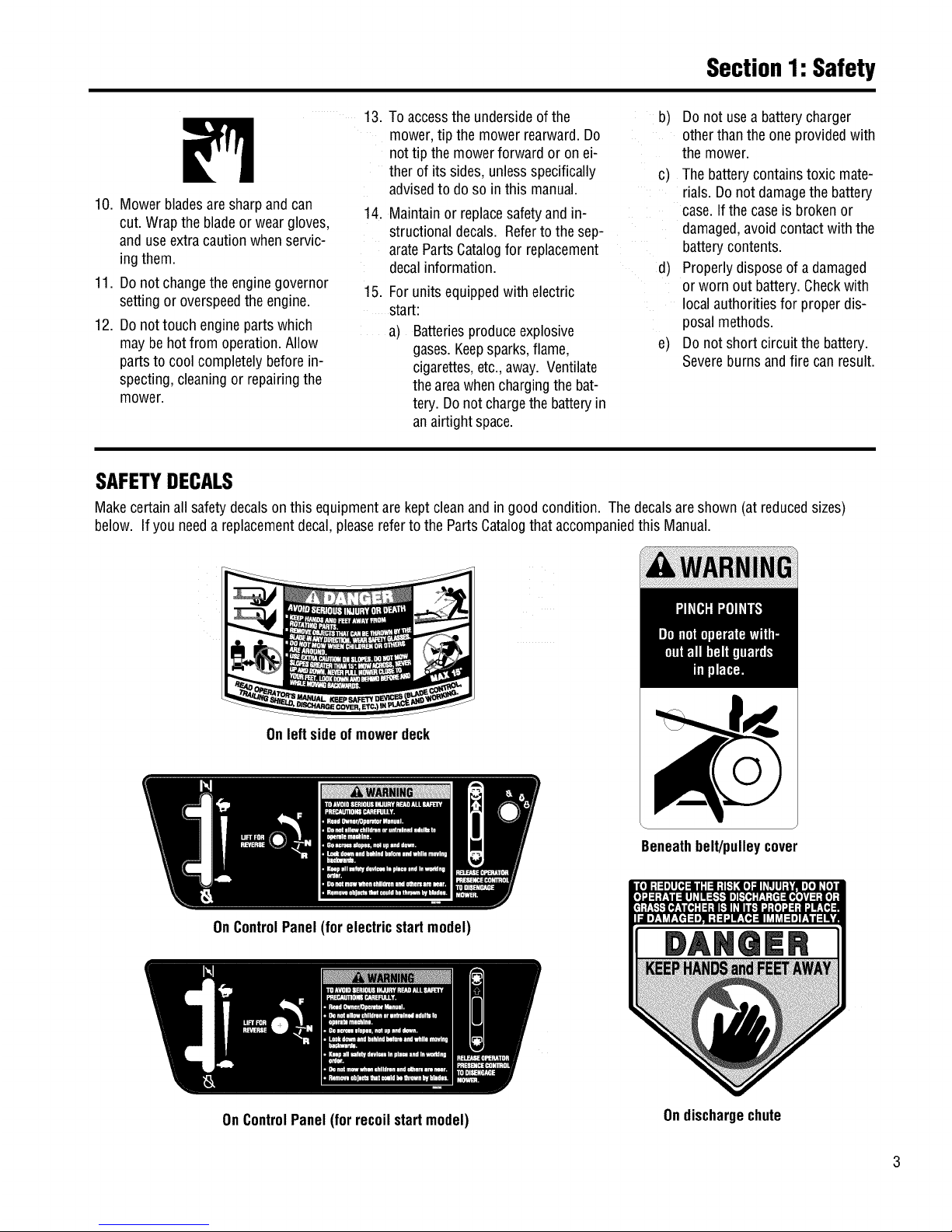
SAFETYDECALS
Makecertainall safetydecalsonthis equipmentare keptcleanandin good condition. Thedecalsareshown (at reducedsizes)
below. If you needa replacementdecal,pleasereferto the PartsCatalogthataccompaniedthis Manual.
Onleftside ofmowerdeck
OnControlPanel(for electricstartmodel)
Beneathbelt/pulleycover
OnControlPanel (for recoilstartmodel)
DANQER
Ondischargechute
Page 6
Assembly
ASSEMBLYSTEPS
To preventpersonal injury or property
damage, do not attempt to start the
engine until all assembly steps are
complete and you have read and
understand the safety, controls and
operatinginstructionsinthismanual.
INTRODUCTION
Pleasecarefullyfollow theseassembly
stepsto properlyprepareyour machine
for use. Werecommendthatyou read
this Sectionin its entiretybeforebegin-
ningassembly.
STEP1: Unpacking Mower
NOTE:LEFTand RIGHTsides ofthe unit
areasviewedfrom the operator'sposi-
tion behindthehandlebars.
1. Cutstraps, if present,securingunit
to pallet. Leaveuniton pallet during as-
sembly(to safelyremoveunit from pal-
let, wait until youhavecompletedas-
semblysteps 1-4).
2. Removeanyprotectivepackaging
from aroundthe handlebars.Cutthe
plastictie strapsholdingthecontrol rods
and struts tothe handlebars.
NOTE:All referencesto left, right,front
and rearof the machineare determined
bystandingbehindthehandlebarsand
facingthe direction offorward travel.
INSPECTIONAFTERDELIVERY
Inspectthe shippingcrateand machine
immediatelyafterdelivery. Makesure
neitherthe carton/cratenor the contents
havebeendamaged.
If you find or suspectany damage,con-
tact thecarrier(truckingcompany)
immediately. Informthem of thespecific
damageandthatyou wish to file a claim.
To protectyour rights, besureto put
this in writing to thecarrierwithin 15
days. Thecarrierwill letyou knowhow
to proceedwithyour claim. Pleaseletus
knowif you needany assistance.
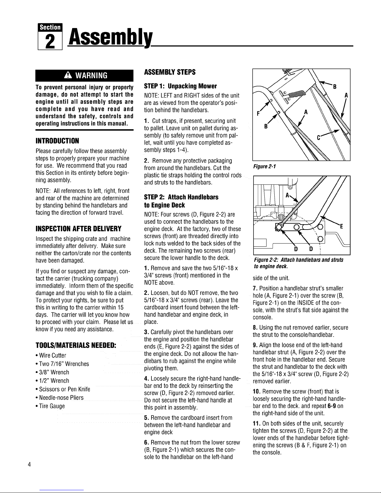
STEP2: Attach Handlebars
to Engine Deck
NOTE:Fourscrews(D, Figure2-2)are
usedto connectthehandlebarsto the
enginedeck. At the factory, two of these
screws (front) arethreadeddirectlyinto
lock nuts weldedto thebacksidesof the
deck.The remainingtwo screws (rear)
securethe lowerhandleto the deck.
1. Removeandsavethe two 5/16"-18 x
3/4"screws (front) mentionedin the
NOTEabove.
2. Loosen,but do NOTremove,the two
5/16"-18x 3/4" screws(rear). Leavethe
cardboardinsertfound betweenthe left-
hand handlebarandenginedeck,in
place.
3. Carefullypivotthehandlebarsover
• Wire Cutter
• Two7/16" Wrenches
• 3/8" Wrench
• 1/2" Wrench
• Scissorsor PenKnife
theengineandpositionthe handlebar
TOOLS/MATERIALSNEEDED: ends(E, Figure2-2) againstthe sides of
theenginedeck.Do not alloow thehan-
dlebarsto rubagainsttheenginewhile
pivoting them.
4. Looselysecurethe right-handhandle-
barendto the deck byreinsertingthe
screw(D, Figure2-2) removedearlier.
• Needle-nosePliers
Donot securethe left-handhandleat
• Tire Gauge this pointin assembly.
5. Removethecardboardinsertfrom
betweentheleft-handhandlebarand
enginedeck
8. Removethenut from the lower screw
(B,Figure2-1) which securesthecon-
soleto thehandlebaron theleft-hand
Figure2-1
D D ,
i
Figure2-2:Attachhandlebarsandstruts
toenginedeck.
sideof the unit.
7. Positiona handlebarstrut's smaller
hole (A, Figure2-1) overthescrew(B,
Figure 2-1) on the INSIDEofthe con-
sole,with the strut's flat sideagainstthe
console.
8. Usingthe nut removedearlier,secure
thestrut to theconsole/handlebar.
9. Align theloose endof theleft-hand
handlebarstrut (A,Figure2-2) overthe
front holein the handlebarend.Secure
thestrut and handlebartothedeckwith
the5/16"-18x3/4" screw(D, Figure2-2)
removedearlier.
10. Removethe screw (front) that is
looselysecuringthe right-handhandle-
barendto the deck.and repeat6-9 on
the right-handsideof the unit.
11. On bothsidesofthe unit, securely
tightenthe screws(D, Figure2-2)atthe
lowerends of the handlebarbeforetight-
eningthescrews (B & F,Figure2-1) on
theconsole.
Page 7
Section2: Assembly
STEP3 ATTACHINGTHEBATTERY
CABLES(MODEL F753B)
Thepositive batteryterminal is marked
Pos.(+). Thenegativebatteryterminalis
markedNeg.(-).
Themowerisshipped with thepositive
(Red)cablesecuredto the positiveter-
minal (+) onthe battery.Attachthe
ground (Black)cableto the negativeter-
minal (-) onthe battery,asfollows:
1. Removethe plasticbatterycover (G,
Figure.2-3) byunthreadingthe two wing
nuts (H, Figure. 2-3) which secure it to
the batteryhold-down rods (I, Figure.2-
3)
2. Remove the hex bolt and hex nut
from the groundcable/ heavyblackwire
(E,Figure.2-3).
3. Securetheground cableto thenega-
tive batteryterminal (-) with the bolt and
hexnut just removed.
IMPORTANT:
• If the batteryis putinto serviceafter
the dateshownontop of battery,
chargethe batteryasinstructedin the
Maintenencesectionof this manual
prior to operatingthetiller.
STEP4: Attach Control Rods
A. AttachWheelDriveControlRod
1. Locatethewheel drivecontrol rod(F,
Figures2-4A & 2-7) and removethe an-
gledendfrom theleft handlebarby re-
movingthe hairpinclip whichsecuresit
to theWheelDriveControllever(V,
Figure2-4A)
2. Atleft sideof enginedeck,insert
swivelblock (H,Figures2-4 & 2-5) on
wheeldrive control rod into wheeldrive
control arm (U, Figure2-4).
3. Adda5/16"washer(A, Figure2-4)
andsecurewith a hairpinclip (B).
4. Atupperend ofcontrol rod,re-insert
the angledend into the Wheel Drive
Controllever(V,Figure2-4A) and re-
attach with hairpinclip (BB) removed
earlier.
B.AttachOperatorPresenceControl
Rod
1. LocatetheOperatorPresenceControl
rod (E, Figures.2-4and 2-5). At bottom
ofcontrol rod, insert swivelblock (G,
Figures2-4 & 2-5) into control arm (T,
Figure2-4).
H
Black
(NegativeCable)
H
Red /
(PositiveCable)
Figure2-3: Connectwireterminalstobatteryterminals.
Controlrodsare adjusted at the fac-
tory andshouldnot requireadditional
adjustmentduringassembly.Afteras-
sembling unit, control rod
adjustment should be checked (and
re-adjusted,ifnecessary)accordingto
informationin Maintenance Section.
Failureto follow this instructioncould
result in severe personal injury or
propertydamage.
2. Addone5/16"washerand secure
with hairpinclip.
C.AttachBladeDriveControlRod
1. Locatethe bladedrivecontrol rod (C,
Figure2-5). Insertoneendof control rod
into bladedrivebracket(D,Figure2-5).
Add one5/16"washerandattachwith
hairpinclip (CC).
2. Insertthe otherendof rod into bot-
tom endof BladeDriveControl lever(J,
Figure2-5). Add one5/16"washerand
attachwith hairpin clip (AA).
D. AttachandAdjustGearSelectLever
NOTE:The retainingplate(N,Figure2-5)
mentionedin thefollowing stepsis se-
curedto the rearofthe mowerwith two
screws (O, Figure2-5) and1/4"-20 lock-
nuts.Removethe retainingplateand
saveit, along with thetwo screws,be-
fore proceedingwith assembly.
W
H A,B _G
Figure2-4:Left-handcontrolrodsdetail.
Page 8
Section2: Assembly
BB
Figure2-4A:Attachwheeldrivecontrolrod
tolever.
1. Removethevinyl grip (B,Figure2-6)
from the gearselectlever (I). Placethe
woodedgeagainsttheedgeofthe grip
andslowly pull off the grip.
2. Insertnylon bushing(Z, Figure2-6)
up into console(L).
3. Slidespringandwashers(J) down
ontogearselectlever.
4. Insertgearselectlever(I) upthrough
nylonbushing(Z)in handlebarconsole
(L).Guidepin (K)ongearselectleverinto
grooveinshift quadrant(P).
5. Holdlower part of gearselectlever(I,
Figure2-7) againstbracket(M). Position
retainingplate(N), removedearlier, as
shown in Figure2-7(platebelow
bracket). Secureplatewith two 1/4"-20x
1/2"screws(0) and1/4"-20 Iocknutsre-
movedearlier.
6. Slidegrip (B, Figure2-6) backonto
gearselectlever (I).
7. Rotategearselectlever(I, Figures2-
6 & 2-7) clockwiseuntilspur (K - short
rod) ongearselectrod stops in theneu-
tral position detenton theshift pattern
quadrant(Figure2-6).
8. Moveshift arm (X, Figure2-7)from
sideto sideas necessaryintoeachtrans-
missiongeardetentuntil transmissionis
in neutral.
NOTE:Movingshift arm(X) allthe wayto
theleft, andthen onenotch backtothe
right, should puttransmissioninto neu-
tral. Whentransmissionis in neutral,unit
will movefreely whenpushedwhilehold-
ingthe OperatorPresenceControllever
(W, Figure2-5) down.If transmissionis
NOTin neutral,therewill beaslight drag
on the wheelswhenpushingunit.
W
J
V
F
G N
Figure2-5:Rearviewofcontrolrods.
0
M
C
f
2
K
Pin(K)mustbe inthisdetent
whentransmissionneutralis --_
adjusted.
Figure2-6: Detail - GearSelectLeverin Neutral(N) position.
6
Page 9
Section2: Assembly
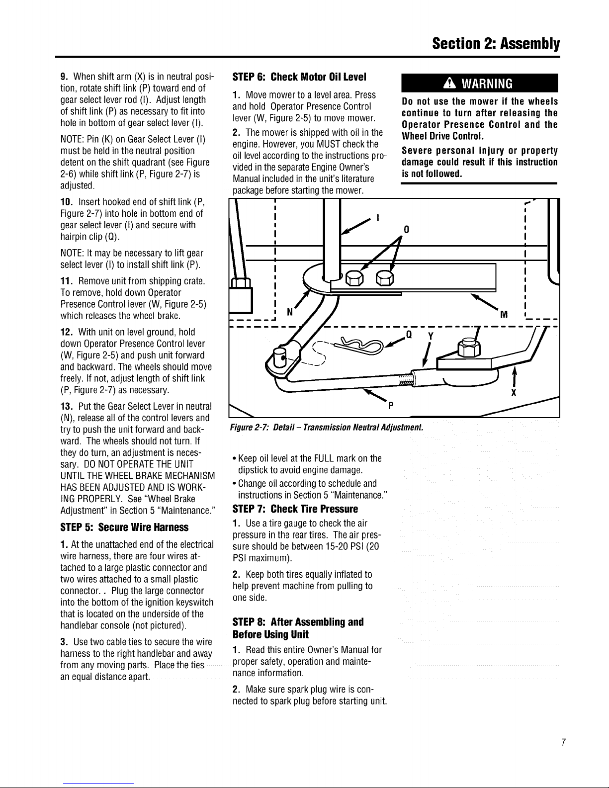
9. Whenshift arm (X)is in neutralposi-
tion, rotateshift link (P)toward endof
gearselectlever rod (I). Adjustlength
of shift link (P)asnecessaryto fit into
hole in bottomof gearselectlever(I).
NOTE:Pin(K) on GearSelectLever(I)
must beheld inthe neutralposition
detentonthe shift quadrant(seeFigure
2-6) while shift link(P, Figure2-7) is
adjusted.
10. Inserthookedendof shift link (P,
Figure2-7) into holein bottom end of
gearselectlever (I) andsecurewith
hairpinclip (Q).
NOTE:Itmay benecessaryto lift gear
selectlever (I) to install shift link (P).
11. Removeunitfrom shippingcrate.
Toremove,hold down Operator
PresenceControllever (W, Figure2-5)
which releasesthewheelbrake.
12. Withunit on levelground,hold
downOperatorPresenceControllever
(W, Figure2-5) and pushunitforward
and backward.Thewheelsshouldmove
freely.If not, adjust length of shift link
(P, Figure2-7)as necessary.
13. Putthe GearSelectLeverin neutral
(N), releaseall of the control leversand
try to pushthe unitforward and back-
ward. Thewheelsshould notturn. If
they doturn, an adjustmentisneces-
sary. DONOTOPERATETHEUNIT
UNTILTHEWHEELBRAKEMECHANISM
HASBEENADJUSTEDAND ISWORK-
INGPROPERLY.See"WheelBrake
Adjustment"in Section5 "Maintenance."
STEP5: Secure Wire Harness
1. Atthe unattachedendof theelectrical
wire harness,therearefour wires at-
tachedto a largeplasticconnectorand
two wires attachedto a small plastic
connector.. Plugthelargeconnector
intothe bottom ofthe ignitionkeyswitch
that is locatedonthe undersideofthe
handlebarconsole(notpictured).
3. Usetwo cableties to securethewire
STEP6: Check Motor Oil Level
1. Movemowerto a levelarea.Press
and hold OperatorPresenceControl
lever(W,Figure2-5) to movemower.
2. Themoweris shippedwith oil in the
engine.However,youMUSTcheckthe
oil levelaccordingto theinstructionspro-
videdintheseparateEngineOwner's
Manualincludedinthe unit'sliterature
packagebeforestartingthemower.
Do not use the mower if the wheels
continue to turn after releasing the
Operator Presence Control and the
WheelDriveControl.
Severe personal injury or property
damagecouldresult if this instruction
isnotfollowed.
I f o
Figure2-7:Detail- TransmissionNeutralAdjustment.
• Keepoil levelatthe FULLmarkon the
dipstick to avoidenginedamage.
• Changeoil accordingtoscheduleand
instructionsin Section5 "Maintenance."
STEP7: Check Tire Pressure
1. Useatire gaugeto checktheair
pressurein the reartires. The air pres-
sureshould bebetween15-20 PSI (20
PSImaximum).
2. Keepbothtires equallyinflatedto
helppreventmachinefrom pullingto
oneside.
STEP8: After Assemblingand
Before UsingUnit
1. ReadthisentireOwner'sManualfor
harnessto theright handlebarandaway o.
from any movingparts. Placethe ties propersaTety,operationand mainte-
anequaldistanceapart, nanceinformation.
2. Makesuresparkplug wire iscon-
nectedto sparkplug beforestarting unit.
Page 10
FeaturesandControls
Before operating mower, be sure to
read all safety, controlsandoperating
instructions in this Manual and on
decalslocatedonmachine.
Severe personal injury or property
damage couldresult it this instruction
isnotfollowed.
IMPORTANT: THE MOWER IS
EQUIPPED WITH A BLADE-BRAKE-
CLUTCHCONTROLSYSTEMWHICH IS
DESIGNED TO STOP THE MOWER
BLADESWITHIN THREE(3) SECONDS
AFTERRELEASEOF THE OPERATOR
PRESENCECONTROL. THIS SYSTEM
WILL STOPTHEBLADESBUTNOTTHE
ENGINE.THEREFORE,YOUCANDISEN-
GAGETHE BLADEDRIVEAT ANYTIME
WITHOUT HAVING TO STOP AND
RESTARTTHEENGINE.THIS FEATURE
IS PARTICULARLYUSEFULWHENYOU
NEEDTO CROSSGRAVELDRIVESOR
ROUGHTERRAIN AND YOU DO NOT
WANT THE SPINNING BLADES
TO STRIKE STONES OR HIDDEN
OBSTACLES.
MOWERFEATURESAND
CONTROLS
This sectiondescribesthe various
featuresand controlson the unit. Refer
to the nextsection "Operation"for
detailedoperatinginstructions. Also,
readthe separateEngineOwner's
Manualfor adetailedexplanationofthe
proper useofthe enginecontrols.
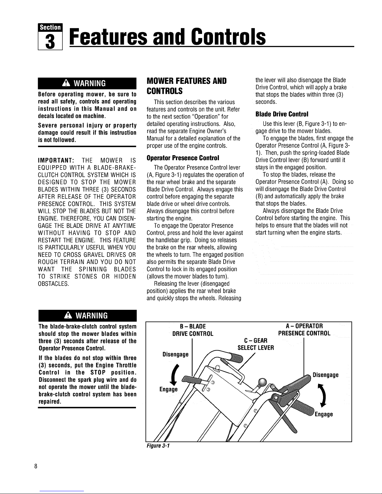
Operator Presence Control
TheOperatorPresenceControllever
(A, Figure3-1) regulatesthe operationof
the rearwheelbrakeandtheseparate
BladeDriveControl. Alwaysengagethis
control beforeengagingtheseparate
bladedriveor wheeldrivecontrols.
Alwaysdisengagethis control before
startingthe engine.
Toengagethe OperatorPresence
Control,pressand holdthe leveragainst
the handlebargrip. Doingso releases
the brakeontherearwheels,allowing
the wheelsto turn. Theengagedposition
alsopermits the separateBladeDrive
Controlto lock in its engagedposition
(allowsthe mowerbladesto turn).
Releasingthe lever (disengaged
position) appliesthe rearwheelbrake
andquicklystopsthe wheels. Releasing
the leverwill alsodisengagethe Blade
DriveControl,which will apply a brake
that stops the bladeswithinthree (3)
seconds.
Blade Drive Control
Usethis lever(B, Figure3-1) to en-
gagedriveto themower blades.
Toengagethe blades,first engagethe
OperatorPresenceControl(A,Figure3-
1). Then,pushthe spring-loadedBlade
DriveControllever(B)forward until it
stays in theengagedposition.
Tostop the blades,releasethe
OperatorPresenceControl(A). Doingso
will disengagethe BladeDriveControl
(B) andautomaticallyapplythe brake
that stops the blades.
AlwaysdisengagetheBladeDrive
Controlbeforestarting the engine. This
helpsto ensurethatthe bladeswill not
startturning whenthe enginestarts.
The blade-brake-clutchcontrolsystem
shouldstop the mower blades within
three (3) secondsafter release of the
OperatorPresenceControl.
If the bladesdo not stopwithin three
(3) seconds, put the Engine Throttle
Control in the STOP position.
Disconnectthe sparkplugwire and do
not operatethe moweruntil the blade-
brake-clutchcontrol systemhas been
repaired.
B- BLADE
DRIVECONTROL
Disengage
Engage
C- GEAR
SELECTLEVER
A-OPERATOR
PRESENCECONTROL
Disengage
Engage
Figure3-1
Page 11
Section3: FeaturesandControls
Operating Symbols Varioussymbolsare usedon the mowerto indicatecontrol settings (your modelmay nothaveall of the
symbols).Thesesymbolsareshown below with a descriptionof their meaning.
ENGINE ENGINE ENGINE
FAST SLOW CHOKE ENGAGE DISENGAGE STOP START RUN
Gear Select Lever
Usethis lever (C,Figure3-1) to select
anyof four forward groundspeeds(1 -
Slow,2 and3 - Medium,4 - Fast),N
(Neutral)and R (Reverse).Thegearshift
patternisshown in Figure3-2.
Toavoiddamagingthetransmis-
sion, donotshiftgearswhenthe
mowerismoving.
Forforward travel,useoneof the four
numberedsettings.Toselectreverse,
shift to neutralandthenpull upon the
lever.Turnthe leverto theR (reverse)
positionand releasethe lever.
Putthe leverin N (neutral)to manu-
ally pushthe mowerand whenthe
moweris not in use.
PresenceControlalong with theWheel
DriveControl.
Whenstarting theengine,theWheel
DriveControlshouldbedisengaged(re-
leased).This helpsto ensurethat the
wheelswill not start turning whenthe
enginestarts.
Do notengagetheWheel DriveControl
without first engaging the Operator
Presence Control. Doing so could
resultin wear or damageto the wheel
brakemechanism.
Figure3-2:
Shiftpattern
onconsole.
A- OPERATOR
PRESENCECONTROL
Disengage
Engage
Wheel Drive Control
Usethis lever (D, Figure3-3)to en-
gageanddisengagedriveto the wheels.
Toengagethe wheels,first selecta
forward or reversegearwith theGear
SelectLeverandsqueezetheOperator
PresenceControl(A, Figure3-3). Then,
squeezetheWheelDriveControllever
(D)againstthe handlebargrip. The
ground speedcanbevariedby increas-
ing or decreasingpressureon the lever.
Toavoidsuddenacceleration,slowly
squeezetheleverwhenfirstengaging
thewheels.
Releasethe WheelDriveControlto
disengagethewheels.Thewheelswill
graduallyslow to a stop. NOTE:Tostop
the wheelsquickly, releasethe Operator
J Engage
Disengage
D- WHEEL
DRIVECONTROL
Figure3-3
Cutting Height Control Lever
Usethis lever(E, Figure3-4) to adjust
thecutting heightfrom 1to 4 inches.
Notethat actualcutting heightswill vary
accordingto soil conditions.
Turnthe leverclockwiseto raisethe
heightor counterclockwiseto lowerthe
height. Adecalandpointer (notillus-
trated) onthe right sideofthe mower
deckshow the cutting heightsettings
rangingfrom A(highest)to G(lowest).
Figure3-4
Mulcher Cover
Themulchercover (F,Figure3-5) is
pre-installedatthe factory. It must be
kept in placewhen using the unit asa
mulchingmower. The mulchercoveris
designedto keepthedischargechute
raisedupwhile you mow. Whenthe
cover is removedfor side-discharge
mowing,the dischargechutelowers.
Referto "4. SelectMulching or Side-
DischargeMowing"in the Operation
Sectionfor mulchercoverinstallation
instructions.
Figure3-5
Page 12
Section3: FeaturesandControls
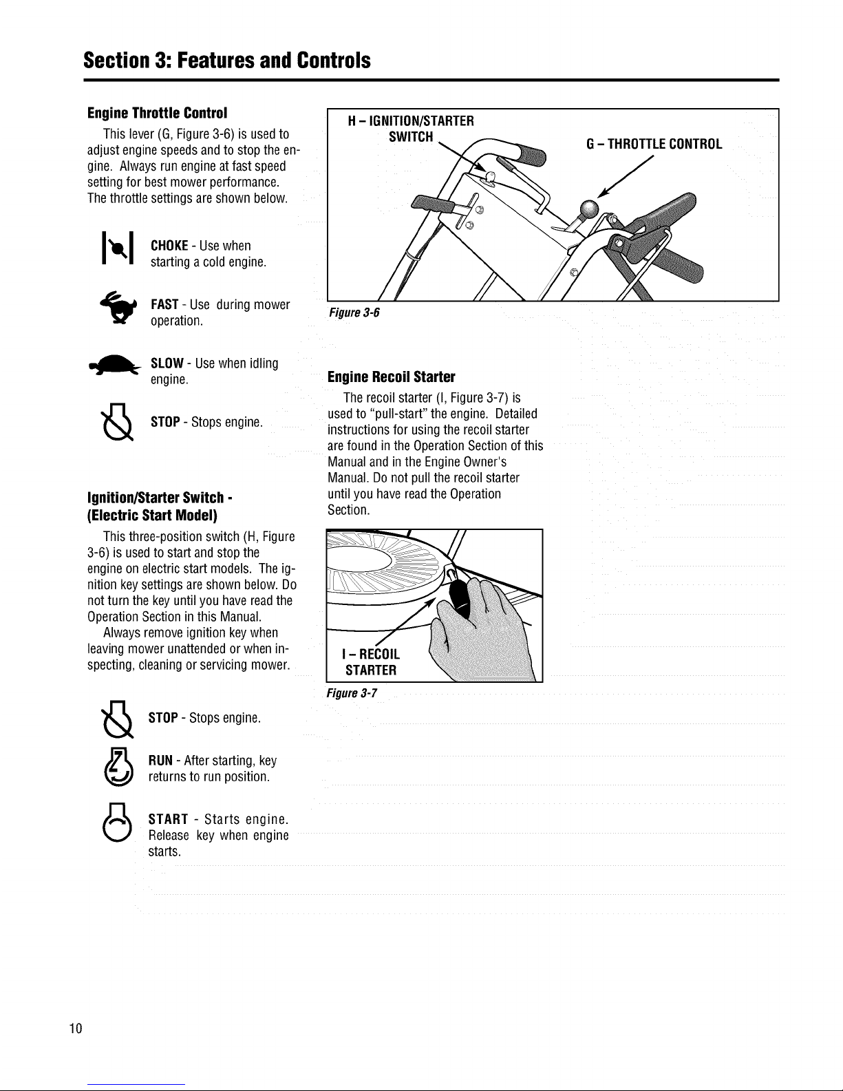
Engine Throttle Control
This lever(G,Figure3-6) is usedto
adjust enginespeedsandto stopthe en-
gine. Alwaysrun engineat fastspeed
settingfor bestmower performance.
Thethrottle settings areshown below.
H- IGNITION/STARTER
SWITCH
G- THROTTLECONTROL
J
I_1 CHOKE-Usewhen
startinga coldengine.
FAST- Use during mower
operation.
Figure3-6
_._ SLOW- Usewhenidling
engine.
STOP- Stopsengine.
Ignition/Starter Switch -
(Electric Start Model)
Thisthree-positionswitch (H, Figure
3-6) is usedto startand stop the
engineon electric start models. Theig-
nitionkeysettings areshown below.Do
notturn the keyuntilyou havereadthe
OperationSectioninthis Manual.
Alwaysremoveignition keywhen
leavingmower unattendedor when n-
specting,cleaningor servicing mower.
Engine Recoil Starter
Therecoilstarter (I, Figure3-7)is
usedto "pull-start" the engine. Detailed
instructionsfor usingtherecoilstarter
arefound in theOperationSectionof this
Manualandin the EngineOwner's
Manual.Donot pull the recoilstarter
untilyou havereadthe Operation
Section.
I - RECOIL
STARTER
STOP- Stopsengine.
RUN- Afterstarting, key
returnsto run position.
Figure3-7
START - Starts engine.
Releasekey when engine
starts.
10
Page 13
Operation
Before operating mower, be sure to
read all safety, controlsandoperating
instructions in this Manual and on
decalslocatedonmachine.
Severe personal injury or property
damage couldresult if this instruction
isnotfollowed.
BEFOREOPERATINGMOWER
1. Pre-OperaUon Checklist
With the sparkplug wiredisconnected
from thespark plug,performthefollow-
ing checksandservicesbeforeeachuse:
1. ReviewSection1:"Safety"andSection
3, "FeaturesandControls"in this man-
ual. ReadtheseparateEngineOwner's
Manualprovidedwith theunit.
2.Checkunitfor looseor missinghard-
ware.Tightenor replaceasneeded.
3. With the uniton levelground,check
theengineoil level accordingto the
instructionsin the EngineOwner's
Manual. Theoil levelshould beat the
FULLmarkonthe dipstick or up tothe
top ofthe oil fill holeon engineswith-
out a dipstick.
4. Checkall leversfor freedomof move-
ment.Readjustor repairas needed
beforestarting engine.
5. Checkthatall guards andshieldsare
in placeandproperly secured.
6. Inspecttheareato mowedandre-
moveanydebris which couldbe
pickedup andthrown bythe mower
blades.
7. Checkthatthe mulchercoveris prop-
erlyinstalledin the dischargeopening
(seeinstructions in this Section).
Removethe mulchercoverto usethe
side-dischargemowingfeature.
8. Onelectricstart models,checkthat
all wiring connectionsarecleanand
tight.
9. Checktheair pressurein the rear
tires (15-20 PSI). Keeptires inflated
equally.
GASOLINEIS HIGHLYFLAMMABLEAND
ITS VAPORSAREEXPLOSIVE.To help
preventseverepersonalinjuryor prop-
ertydamage:
• Follow gasoline safety rules in
Section1: "Safety" of this Manualand
in the separate Engine Owner's
Manual.
• Neverremovethe gasolinefill cap or
add fuel when indoorsor when engine
is runningor still hot.Allow engineto
coolat leastthree (3) minutesbefore
refueling.
• Keep smokingmaterials, sparksor
flamesfar awayfromfuel tank andfuel
container.
• Store gasoline in an approvedfuel
containerandin a well-ventilatedarea.
Storeit safely outof the reachof chil-
dren. Do notstore gasolinewhereva-
porscan reachan opensparkor flame
or where ignition sourcesare present
(suchas hot water or space heaters,
furnaces,clothesdryers, stoves,elec-
tric motors,etc.).
• Fill tankto 1/2"below bottomoffiller
neckto allowfor fuel expansion.Wipe
up spilled gasoline immediately and
movemowerawayfromgasolinefumes
before starting engine. Securely re-
place caps on fuel tank and fuel
container.
10.Removethefuelcap andcheckthe
levelof gasolineaccordingto the in-
structions in the EngineOwner's
Manual.Cleanaroundfuel fill area
beforeremovingfuel cap. Donot
checkfuel level or addfuelwhile in-
doorsor if engineis running or hot.
Allow engineto cool for three (3)
minutes. Fillthe tankwith fresh,
cleanunleadedgasolinewith a mini-
mum octanerating of 77. Leave1/2"
ofspacefor fuel expansion.Donot
mix oil with gasoline.Donot use
gasolinewhich containsMethanol.
SeetheEngineOwner'sManualfor
instructions and precautionsregard-
ingthe useofgasolinesthat are
blendedwith alcoholsor ethers
(calledoxygenatedor reformulated
gasolines). Securelyreplacecapson
fuel tankandfuel container.
11.Attach sparkplug wireto spark plug
after completingabovechecklist.
2. Set Mower Cutting Height
To avoid personalinjury, do notadjust
cuttingheightwhile wheels or blades
are turning. Release all handlebar
controlsandwait for all motionto stop
beforeadjustingcuttingheight.
1. Releaseall controls beforeadjusting
thecutting height.
2. Adjustthecutting heightfrom 1to 4
inchesby rotatingthe CuttingHeight
Controllever(Figure3-4) eitherclock-
wiseto raisethe heightor counterclock-
wiseto lowerthe height. Notethat ac-
tualcutting heightswill vary according
to grassandsoil conditions. A decaland
pointeron the right side of themower
deckindicatesthe height setting.
3. In heavyor tall grass,it is usually
betterto makethefirst cut at a higher
settingandthen makeasecondcut at
thedesiredheight. In roughterrain, a
highersetting is recommendedasit will
minimizethe chancesof the bladestrik-
ing the ground or hidden obstructions.
11
Page 14

Section4: Operation
3. TestBlade-Brake-Clutch
Control System
Themower isequippedwith a blade-
brake-clutchwhich is designedto stop
the mowerbladeswithin three(3)
secondsafter releaseofthe Operator
PresenceControlor the BladeDrive
Control. Nevertamperwith, or attempt
to defeatthe purposeofthis safety
device.
Thecontrol systemisa mechanical
devicewhich issubject to wear.
Therefore,testthe operationofthe
blade-brake-clutchcontrol systembefore
eachuseofthe mower.Referto "Blade
BrakeControlTest"atthe end ofthis
Section.
4. Select Mulching or Side-
Discharge Mowing
Beforeinstallingor removingmulching
cover, stop engine, wait for parts to
stopmoving,anddisconnectsparkplug
wire. Remove ignition key on electric
startmodels.
Youcanusethe mowereitheras a
mulchingmoweror asaside-discharge
mower. To usethe mulchingfeature,in-
sert the mulchercover asdescribed
below. Removethemulchercoverto
side-dischargegrassclippings. The
mulchercover is designedto keepthe
dischargechute raisedup while mowing.
Whenthe cover is removed,the dis-
chargechutewill loweritselffor side-
dischargemowing.
Toinstall or removemulchercover:
1. Stopthe engineand waitfor all parts
to stop moving. Disconnectthespark
plug wire from thespark plug. Remove
theignition keyon electric start models.
2. Toinstallthe cover,insertthe right-
sidetab of thecoverinto thefront sup-
port bracket(A, Figure4-1). Insertthe
cover into thedischargeopening,mak-
ing sure that theslot (B) in theleft side
of thecover is completelyengagedinthe
rearedgeof thedeckopening.
B
Figure4-1:Mulchercover
STARTINGANDSTOPPING
THEENGINE
Do not operate the engine in an
enclosed area. Engine exhaust
containscarbon monoxide, a deadly
gas that is odorless, colorless and
tasteless. Alwaysrunengineoutdoors
and make sure there is adequate
ventilation.
3. Toremovethe cover,slidethecover
to the right (front of mower)to disen-
gagethe slot (B) from the mowerdeck
andthenprythe left-sideof the cover
out andoff.
MOVINGTHEMOWERWITHOUT
ENGINEPOWER
Themowercan bemanuallypushed
or pulledbyputting the GearSelect
Lever(C,Figure4-2) in N(neutral)and
pressingandholdingthe Operator
PresenceControl(A, Figure4-2) down
againstthe handlebargrip.
To stopthewheelsatanytime.
releasetheOperatorPresenceControl.
ToStart the Engine
1. Movemowerto a levelarea.
2. Releaseall controls on mowerto pre-
ventwheelsor mower bladesfrom rotat-
ing when enginestarts.
3. MoveEngineThrottle Control(E,
Figure4-2) fully upwardto chokesetting
to starta cold engineor to fast (rabbit)
settingto starta warmengine.
Toavoidinjury:
• Keephandsand feet clear of mower
blades or other rotating parts.
• Lookbehindyouto be surethereare
no obstacles before pulling recoil
starterrope.
F-Ig
B- Blade Drive
Control
C - Gear Select Lever
E - Engine Throttle
Control
A-Operator
Presence Control
I
Figure4-2: MowerControls
D- Wheel Drive Control
12
Page 15

Section4: Operation
4. Tostart engineusing recoil starter:
A. Standonleft side(as viewedfrom
behindhandlebars)of machine.Be
sureyour feet aresafelyawayfrom
the undersideof the mowerdeckand
all mowercontrolsare released.
Placeonefoot ontop of tire.
B. Graspstarterropehandle(Figure3-
7) andpull slowly until ropepulls
slightly harder.Letroperewind
slowly. Thenpull ropewith a rapid,
full arm stroke. Letropereturn
slowly. If enginefails to startafter
threepulls, repeatinstructionsstart-
ingwith Step2 (try settingthrottle at
fast setting).
C. Whenenginestarts, operateinfast
throttle setting(movethrottle from
chokesettingto fastsetting).
5. Tostart engineusing electricstarter:
A. Standbehindthehandlebarsandre-
leaseallmowercontrols.
B.Turnignition key(F, Figure4-2)fully
clockwiseto crank engine.To avoid
damageto startermotor,do not
crank enginefor longerthanfive sec-
ondsat atime.Also, allow 15sec-
ondsbetweeneachstart attempt.If
enginefails to start afterthreeat-
tempts, repeatinstructionsstarting
with Step2 (try settingthrottle atfast
setting).
C. Whenenginestarts,releasekeyandit
will returnto therun (middle) posi-
tion.
D. Operateengineatfast throttle setting
(movethrottle from chokesettingto
fast setting).
NOTE:Ifthe electricstart system is not
functioning,theenginecanbestarted
with the recoilstarter. Todo so,first put
theignition keyin the run (middle)posi-
tion. Thenfollow Steps1-4 above.
Leavethekey inthe run position during
engineoperation.
ToStop the Engine
1. Releaseall mowercontrolsto stop
wheelsor mower blade.
2. Movethrottlecontrol downto slow
(turtle) position. (Wheneverpossible,
graduallyreduceenginespeedbefore
stoppingengine.)
3. MoveThrottleControlall the way
downto stop position orturn ignition
key(electricstart models)fully counter-
clockwiseto stop position.
4. Onelectric start models,removethe
ignitionkey beforeleavingthemower
unattended.
ENGAGINGTHE BLADES
- Fast). Whenfirst practicingwith
the mower,putleverin No.1 setting.
Selectforward speedsaccordingto
mowingconditionsandterrain. Use
slower speedson roughterrain or
whengrass isheavyor thick. The
forward speedcanbeincreasedon
smoothterrain or if thegrass cover
is light. Allowthewheelsto stop
completelybeforeshifting from one
forward speedinto another.
To avoid injuryfrom rotatingblades,
keep face, hands and feet clear of
mowerbladesatall times.
To Engage the Blades
1. Startengineas describedin "To Start
the Engine"instructions. Putengine
throttle in fast speedsetting.
2. Pressandhold OperatorPresence
Control(A,Figure4-2) againsthandle-
bargrip.
3. Slowly pushBladeDriveControl(B,
BeforeengagingtheWheel DriveLever
for the very first time, checkthat the
neutral(N) positionon the GearSelect
Lever is properly adjusted. See
"Neutral Adjustment" in Section 5:
Maintenance for the procedure to
follow.
Failureto follow this instructioncould
result in personal injury or property
damage.
Figure4-2) fully forward until it staysin C.
the engagedposition. Thebladesare
nowrotating.
To Stop the Blades
Tostop the blades,releasetheOperator
PresenceControl.
TO ENGAGETHEWHEELS
• To avoiddamagingthetransmission,
donotshiftgearswhilein motion.
• To avoiddamagingthe wheel brake
mechanism,do notengagethe Wheel
DriveControlwithoutfirst engagingthe
OperatorPresenceControl.
1. Start engineasdescribedin "To
Startthe Engine"instructions.
2. FORFORWARDTRAVEL:
Tostart the wheels,slowly squeeze
theWheel DriveControl(D, Figure4-
2). Theharderyou squeeze,the
fasterthe wheelswill turn. To avoid
suddenacceleration,slowlysqueeze
the lever.
D.TOSTOPTHEWHEELS:
• To stopdrive powertothewheels,
releasetheWheelDriveControl. The
wheelswillgraduallyslowto astop.
• To quickly stop thewheels,release
boththe WheelDriveControland
theOperatorPresenceControl.
3. FORREVERSETRAVEL:
Toavoidinjuryorpropertydamage:
• Look behind the mower before
andduringreverseoperation.
• Stopthemowerbladesbeforeeperat-
ingin reverse.
A. PressandholdOperatorPresence
Control (A, Figure4-2) againsthan-
dlebargrip.
B. Putthe GearSelectLever(C,Figure
4-2) intoone ofthe numberedset-
tings (1 - Slow,2 and3 - Medium,4
A. Stop the mowerbladesandwheelsby
releasingtheOperatorPresence
Control(A, Figure4-2).
B. Pressandhold OperatorPresence
Controlagainsthandlebargrip.
13
Page 16

Section4: Operation
C.
O.
E,
Putthe GearSelectLever(C, Figure
4-2) in R(reverse)setting byfirst
movingleverto N(neutral). Then
pull lever up,turn itto Rposition,
and releaselever.
To startthewheels,slowly squeeze
WheelDriveControl(D, Figure4-2).
Toavoid suddenacceleration,slowly
squeezethe lever.
TOSTOPTHEWHEELS:
• To stopdrive powertothewheels,
releasetheWheelDriveControl.The
wheelswillgraduallyslow to astop.
• To quickly stop thewheels,release
both theWheelDriveControland
theOperatorPresenceControl.
• ReturntheGearSelectLeverto the
N (neutral)positionwhenyou have
completedreverseoperation. Allow
thewheelsto stop completelybe-
foreshifting from R(reverse)into a
forward speed.
MowWhen
LawnIsDry
Forbestresults,avoidcuttinggrass
whenit iswet. Wetgrasstendsto form
clumpswhich interferewith thecutting
action. Thebesttime to mow isin the
lateafternoonor earlyeveningwhenthe
grassis usuallydry.
1
CutTop1/3 of /-_
GrassBlades __'
Cuttingmorethan 1/3 of grasslength
maycausethe grassto becomeexces-
sivelydry. Intall grass,it maybeneces-
saryto mowat a highersetting andthen
mow againat thedesiredheight. NOTE:
Thecutting heightis critical to achieving
a well-groomedlawn. Youshouldexper-
iment with varioussettingsto find that
"just right" cutting height.
MAKINGTURNS..... _
VaryCuttingPattern
Themowerturns easily bypushing
thehandlebarsin the oppositedirection
that you wantto turn. Thedifferential
mechanisminsidethe transaxlewill
allowthe inside turning wheelto stop or
slow down whilethe outsideturning
wheelis poweredbythe drive system.
Reducethewheelspeedbeforeturn-
ing the mower.Fortight turns, disen-
gagethe WheelDriveControlandmanu-
Varythe cutting patternfrom weekto
weekto help preventmattingofthe
grass. Oneweek,mowfrom northto
south,the nextweekmow from eastto
west. Overlapseveralincheswhen
mowingto obtainan evenappearance.
MowingonSlopes
allypush the mowerthroughthe turn (if
needed,putthe GearSelectLeverin
neutralso the wheelsturn freely).
MOWINGTIPSANDHINTS
Toavoidinjuryorpropertydamage:
• Before mowing, thoroughly inspect
area where mower is to be usedand
remove all stones, sticks, wires,
bones,nailsandotherforeignobjects.
• Disengage mower blades before
crossinggraveldrives, roads, or side-
walksto preventbladesfrom throwing
stonesor otherhazardousobjects.
Toavoidinjury orpropertydamage:
• Maximum safe operating angle
is150.
• Exceedingmaximum safe operating
angle may cause tipping or loss of
footing.
• Donotmowwet slopes.
• Mowacrossslopes,notupanddown.
• Exercise extreme caution when
changingdirectiononslopes.
MulchingLeaves
• The mowercan beusedto mowfallen
leaves.Theleafparticlesfilter downinto
thelawn andprovideaddedfertilizer.
• The leavesmust bedry in order to be
mulched.
• Usea slowerground speedifthe
leavesarenot mulchedinto fine parti-
cles.
• If you mulch oakleaves(whichaddacid
tothe soil), addlime to the lawn inthe
springto reducetheacidityofthe soil.
KeepMowerBladesSharp
Forbestmowerperformance,keepthe
bladessharp. Dullbladeswill tear,
bruiseandsplit the endsof grass. See
bladesharpeninginstructions in Section
5: Maintenance.
Donot mowexcessivelysteepslopes
(seeWARNINGstatementthatfollows).
Slowdown andexerciseextremecaution
whenchanging directionon slopes.
Beforemowing on slopes,checktheen-
gine oil levelandmakesurethatthe level
is attheFULLmark. Maintaininga FULL
oil levelis particularlyimportantwhen
operatingon slopesasoil canbe drained
awayfrom vital engineparts.
CleanMowerFrequently
Cleanthe undersideof the mowerdeck
frequentlyto removegrass build-up.
Seemowercleaninginstructionsin
Section5: Maintenance.
PrecisionTrimming
Forprecisiontrimming, usethe slow-
estgearand inch the mower alongby
"feathering"the WheelDriveControl
lever. Or,disengagethe wheeldrive by
releasingtheWheelDriveControlso that
you canmanuallymaneuverthemower
(if needed,putthe GearSelectLever in
neutralso that thewheelsturn freely).
14
Page 17

Section4: Operation
BLADEBRAKECONTROLTEST
Whenthe OperatorPresenceControl
is releasedduringoperationof the
mower,the enginedoesnot stop, but
thebladesshouldstop within three(3)
seconds. The followingtest providesa
visualtest ofwhetherthe BladeBrake
ControlSystemisfunctioning. Perform
this test beforeeachuseof the mower.
1. Parkmoweron aportion of lawn
which has notbeenrecentlymowed.
2. Setthecutting height so the mower
cuts 1/3of thegrassheight.
To avoid personal injury or property
damage,make sure thatthe moweris
ongrass,andthatthe testarea isclear
of foreignobjectsand bystandersbe-
fore you beginthe Blade BrakeControl
Test.
If the OperatorPresenceControlor the
Blade Drive Controlare not adjusted
correctly,the blades may continueto
rotate after release of the Operator
PresenceControl. If the blades do not
stopwithinthree(3) secondsofrelease
ofthe OperatorPresenceControl,move
the EngineThrottleControlto the STOP
position, disconnect the spark plug
wire, andmovethewire awayfromthe
sparkplug. Do not operatethe mower
until the Blade Brake ControlSystem
hasbeenrepaired.
Failureto do this couldresult in per-
sonalinjuryor propertydamage.
3. Starttheengine.
4. PresstheOperatorPresenceControl
downagainstthe handlebargrip and
pushthe BladeDriveControlfully for-
ward until it staysin the engagedposi-
tion.
5. Putthe GearSelectLeverin the No.1
setting.
6. Engagethe wheelswith the Wheel
DriveControlanddrivethe mowerfor
severalfeet. Thenreleasethe Operator
PresenceControl.
A.
Lookat the lawn just mowed.The
lawnshould becut upto the point
wherethe OperatorPresenceControl
was released.
B. Pressthe OperatorPresenceControl
againstthe handlebargrip but DO
NOTre-engagethe BladeDrive
Control. Drivethe mowerforward
for severalmorefeet. Releasethe
OperatorPresenceControlandlook
atthe lawn.Thegrassshould NOT
havebeencut. This indicatesthat
theOperatorPresenceControlhas
disengagedthe bladedriveand
stoppedtheblades.
7. If the mowercutsthegrass in Step
6-B,the OperatorPresenceControlis
NOTdisengagingthe bladedrive.
Immediatelystopthe engine,discon-
nectthesparkplugwire,andmovethe
wireawayfromthesparkplug.
8. Donotusethe mower untilthe Blade
BrakeControlSystemhas beenin-
spected,adjustedor repairedbyan au-
thorized dealer.
15
Page 18

Maintenance
Beforeinspecting,cleaningorservicingthemachine,shutoffengine,waitformovingpartstostop,disconnectspark
plugwireandmovewireawayfromsparkplug.Removeignitionkey(elecb'icstartmodels).
Failuretofollowtheseinstructionscanresultinseriouspersonalinjuryorpropertydamage.
Carefully read this Section on mower
and engine maintenance and service.
Performing the required maintenance
according to schedule will ensure the
proper performanceandlong lifeof your
machine.
Beforeinspecting,cleaningor servicing
the machine, shut off engine, make
surethatall movingpartshavecometo
a completestop,disconnectsparkplug
wire and move wire away from spark
plug. Removeignition key on electric
startmodels.
Failureto followtheseinstructionscan
result in personal injury or property
damage.
NOTE: All referencesto left, right, front
and rearof themachinearedeterminedby
standingbehindthe handlebarsandfacing
thedirectionofforwardtravel.
IMPORTANT:REFERTO
MAINTENANCECHARTINTHIS
SECTIONFORA LISTINGOFREGU-
LARLYSCHEDULEDMAINTENANCE
PROCEDURES.
ENGINESERVICE
Routineengineserviceis described
below. Formorecompleteengineser-
vice information, referto theengine
manualprovidedwith your machine.
Forcompleteengineservice,contactan
authorizedenginedealer.
ENGINEOIL
OIL LEVEL:With moweron level
ground,the engineoil levelmust bebe-
tweenthe"ADD"and "FULL"markson
the dipstickatall times. Checkbefore
eachuseandevery5 operatinghours.
OILCHANGE:Ona newengine,change
oil afterfirst 2 hoursof use,then change
oil regularlyas specifiedon the
MaintenanceChart. Referto Engine
Owner'sManualfor oil capacity.
OILTYPE:Useclean,high qualitydeter-
gent oil havinganA.P.I. serviceclassifi-
cation of SE,SFor SG. Useno special
additiveswith oil. Referto the Engine
Owner'sManualfor recommendedSAE
viscosity gradesthat matchthe starting
temperatureanticipatedbeforethe next
oil change.
CheckingOilLevel:
1. Park machineon levelground.
2. Stopengine, waitforpartstostop
moving,anddisconnectsparkplug
wire.
3. Cleanareaarounddipstick (Z,Figure
5-1) to preventdirtfrom enteringoil fill
hole.
4. Removedipstick. Oillevelmustbe
between"ADD" and "FULL"marks. Do
notexceed"FULL" markon dipstick.
5. To addoil, pourslowlyinto dipstick
opening. Whileadding,check oil level
frequently bysecurely replacingdipstick
and removingto readoil level.Wipe dip-
stick cleaneachtime oil levelis
checked.
6. Afterfilling to "FULL"mark,securely
replacedipstick.
ChangingOil:
Changeoil while engineis still warm
from recentoperation. Warm oil flows
morefreely andcarriesawaymore im-
purities.
1.Stopengine, waitforpartstostop
moving,anddisconnectsparkplug
wire.
2. Removedipstick(Z, Figure5-1).
3. Removeprotectivecap(A, Figure5-
2) to exposeoil drain port (B).
4. Pushoil drain hose (D) (includedin
hardwarebagwith unit) onto oil drain
port. Routeother end ofhoseto anap-
propriateoil collectionreceptacle.
5. Twist oil drainfixture (C)to the open
position. Pullout. Drainoil completely.
6. Pushin andtwist oil drain fixture to
the closedposition. Removedrain
hose.Replaceprotectivecap (A).
7. Refillenginewith fresh oil andse-
curelyreplacedipstick.
NOTE:Pleasedisposeofall waste mate-
rialsin an ecologicallyresponsibleman-
ner. Useproperwastematerialstorage
containers.
Figure5-1:BriggsandStrattonengineoil
fill.
Figure5-2:Oildrain.
16
Page 19

Section5: Maintenance
W!_LW:I-'t_II_[_I Beforeinspecting,cleaningorservicingthemachine,shutoffengine,waitformovingpartstostop,disconnectspark
i1"_ plugwireandmovewireawayfromsparkplug.Removeignitionkey(ele_icstartmodels).
MI
Failuretofollowtheseinstructionscanresultinseriouspersonalinjuryorpropertydamage.
ENGINECLEANING
• Stopengine, waitforpartstostop
moving,disconnectsparkplugwire,
andallowenginetocoolbeforein-
spectingorcleaningengine.
• Dailyor more often,beforerunningen-
gine,removegrassand chafffrom recoil
fingerguardor rotatingscreento prevent
enginedamagecausedbyoverheating.
Alsokeepcoolingvanes,governorlink-
age,springsandcontrolsfree of debris.
• Dailyor more often, beforerunningen-
gine,cleanmufflerarea(besure muffler
is cool)to removeall grassandcom-
bustibledebris. If engineis equipped
with a sparkarrestorscreen,removeas-
semblyevery50 hoursfor cleaningand
inspection.Replaceif damaged.
• Grassor chaff mayclog engine'sair
coolingsystem,especiallyafterpro-
longedoperationcutting tall, drygrass.
SeeEngineOwner'sManualfor instruc-
tions on cleaningunderneaththeengine
blowerhousing.
AIR CLEANERSERVICE
Improperair cleanermaintenancecan
causeenginedamage.Refertothe
EngineOwner'sManualfor morecom-
pleteair cleanerserviceinformation.
SERVICESCHEDULE:
Outerfoam pre-cleaner-washand re-oil
every25 operatinghoursor everysea-
son, whicheveroccursfirst.
Innerpapercartridge- clean or replace
every100 operatinghoursor everysea-
son, whicheveroccursfirst.
ToServiceAir Cleaner(Figure5-3):
1. Stopengine,waitfor partsto stop
moving,anddisconnectsparkplug
wire.
2. Unscrewmountingscrewsand/or re-
moveknobs (D). Removecovers(E).
Removepapercartridge(B) andfoam
pre-cleaner(A). Separatefoam pre-
cleanerfrom papercartridge.
3. Washfoam pre-cleaner(A)in liquid
A
Chargebattery only with chargersup-
pliedwith machine.Donotshortcircuit
batterywires. Removeanyjewelry be-
fore working on or near the battery or
electricstart system. Failuretofollow
these instructionscouldresult in per-
sonalinjuryorpropertydamage.
Figure5-3: BriggsandStrattonair cleaner
assembly.
detergentandwarm water. Squeezedry
in aclean cloth.
4. Saturatefoam pre-cleanerinclean
engineoil. Wrapin clean,absorbent
cloth andsqueezeto removeall excess
oil.
5. Replacepapercartridge(B), if
necessary.
6. Reassembleaircleanercomponents.
SPARKPLUG
Inspectthe sparkplug (Figure5-4) after
every 100hours of operation.Besure
the gapis setat .030".Donot reuseplug
if it is severelywornor damaged.
Bestresultsare obtainedwith a new
plug. SeeEngineOwner'sManualto de-
termine proper replacementplug. Use
of incorrectplugcancauseenginedam-
age.
NOTE:Donot cleanspark plug in ma-
chines which useabrasivegrit. Clean
spark plug byscrapingor wire brushing,
or washingwith a commercialsolvent.
BATTERY(if applicable)
Chargebatteryif unit is to bestoredfor
longerthanthreeweeks.Duringthe
mowingseason,the batteryis kept
chargedby the chargingsystemonthe
engine.
ToChargeBattery:
1. Plugchargerconnectorintowire har-
nessconnectorlocatedbelowignition
switch in handlebarconsole.
2. Plugchargerinto120Vwall outlet.
Tightenknobs/screws(D) securely. (Notethat batterychargeris designedfor
Secure coverassembly(E)on air useindoorsandshouldnot beexposedto
cleanerbody. rainorsnow.)
3. Chargebatteryfor 24-48 hours if unit
is to bestoredfor longerthan three
weeks.
.030' FeelerGauge
4. After charging,unplugchargerfrom
outlet,then unplugchargerfrom con-
nector on wireharnesslocatedbelow
handlebarconsole.
CARBURETOR
Thecarburetor isadjustedatthe factory.
It should not needto be reset. If black
exhaustis noted,checkthe air cleaner
first. An over-rich mixture is usually
causedbya poorly servicedor clogged
air cleanerelement,not an improperly
adjustedcarburetor. If readjustmentis
necessary,referto EngineOwner's
Manualor contactyourenginedealer.
Figure5-4: Sparkplug.
17
Page 20

Section5: Maintenance
• !'T_TI-_I-'{_JI_[€']I Beforeinspecting,cleaningorservicingthemachine,shutoffengine,waitformovingpartstostop,disconnectspark
t _ plugwireandmovewireawayfromsparkplug.Removeignitionkey(elecb'icstartmodels).
MI
Failuretofollowtheseinstructionscanresultinseriouspersonalinjuryorpropertydamage.
ENGINESTORAGE Thebelt covermust be removedto per-
form severalmaintenanceprocedures.
If enginewill be unusedfor 30 daysor
more,prepareit for storage byfollowing To RemoveBeltCover:
the recommendedproceduresfound in 1. Stopengine,wait forall partsto
the EngineOwner'sManual. stopmoving,anddisconnectspark
plug wire.
5. Loosenfour mounting bolts (L) se-
curingspindle housing (beneathmower
deck)to mowerdeck.
6. Slidespindlehousing (with pulleyat-
tached)towardcenter.
7. Replacebelt(N) with newbelt.
MOWERSERVICE
Thefollowing maintenance/repairproce-
durescan be performedbyeitherthe
owneror anauthorizedservicedealer.
Seeanauthorizedservicedealerfor
completemowerservice.
TIPPING MOWER FOR SERVICE
and removecover.
To ReinstallBeltCover:
1. Positionbelt cover in place.
2. Securewiththe four screwsremoved
earlier.
2. Removefour screws(R, Figure5-5) IMPORTANT:SETBLADESPERPEN-
DICULAR(90°) TOEACHOTHER.
8. Rotatearm (K)to movespindle
housingandapplytensionto belt. Belt
cogsand pulley groovesmust meshto-
gether.Whenapplying moderatefinger
tension (8-12 Ibs.),beltshoulddeflect
approximately1/2" (12.7mm) at (P),
midpointof deck.
Before servicing undersideof mower,
stop engine, wait for all parts to stop
moving, and disconnect spark plug
wire. Remove ignition key from
keyswifch on electric start models.
Failureto follow this instructioncould
result in personal injury or property
damage.
Whenservicingthe undersideof the
mowerfor anyreason,the mower
should onlybetipped backwardon its
rearwheels(andsecurelyproppedupto
preventit from falling). Tippingthe
mowerforward or to either side could
resultin damageto engine.
TIP:Beforetipping mower, installa
small plastic sandwichstylebag under
the gascapandtighten securely. This
will virtually eliminateanyfuelseepage
from thecap. Besureto removethe
plastic bagbeforere-usingmower.
BELTCOVERREMOVAL
Do not operateunitwithout belt cover
installed. Failureto followthisinstruc-
tion couldresult in personalinjury or
propertydamage.
Figure5-5: Beltcoverremoval.
BLADESPINDLE BELT
REPLACEMENT
Followthis procedureto removeandre-
placethe bladespindledrivebelt (re-
movebladedrive beltfirst; see"Blade
DriveBeltReplacement"inthis Section).
1. Stopengine,wait forall partsto
stopmovinganddisconnectsparkplug
wire.
9. Tightenbolts (L) to 15ft.-Ibs. (20.3
Nm).Tightenscrew (J).
10. Bladesmustnotcontact deck.
Checkandreadjustas needed.
11. Reinstallbladedrive beltand belt
cover (removedearlier).
t
FRO_T
J
MUST BE PERPENDICULAR
TO EACH OTHER
Figure5-6: BladeSpindleBell
2. Removebeltcover(see"BeltCover
Removal").
3. Alignsight holes(0, Figure5-6) in
pulleywith spindlehousing-to-mower
deckmountingbolts (L).
4. Loosenscrew(J) and rotatearm (K)
to the rear.
18
Page 21

Section5: Maintenance
W!_LY_TI:I-'t_II_[_IBeforeinspecting,cleaningorservicingthemachine,shutoffengine,waitformovingpartstostop,disconnectspark
t _ plugwireandmovewireawayfromsparkplug.Removeignitionkey(elecb'icstartmodels).
Failuretofollowtheseinslxuctionscanresultinseriouspersonalinjuryorpropertydamage.
BLADEDRIVEBELT
REPLACEMENT
Followthis procedureto removeand re-
placethe bladedrivebelt. Anassistant
will be needed.
ToRemoveBelt:
1. Stopengine,waitforall partsto
stopmoving,anddisconnectspark
plugwire.
2. Disengagebladedrivecontrol (Figure
5-7) byreleasingall controls onthe
mower.
BladeDriveDisengaged
BladeDriveEngaged
\\
RIGHTVIEW
Figure5-7: BladeDriveControl
3. Removebeltcover (see"BeltCover
Removal").
4. Loosenbeltguides (BandC,
Figure5-8).
5. Moveflap bracket(N, Figure5-8) out
ofthe way by looseningtwo screws (M).
8. Removebelt(A, Figure5-8)from
aroundsheaves.
To InstallBelt:
1. Routebelt (A, Figure5-8) around
sheavesasshown.
2. Haveanassistanthold down
OperatorPresenceControlandthen
pushthe BladeDriveControlforward
until it latchesin place(Figure5-7).
3. With the BladeDriveControlleveren-
gaged,adjustandtighten beltguide (B)
to 1/32- 1/16"awayfrom tensioned
belt. (Besurethat beltdoesnot contact
beltguidewhenbelt isundertension.)
Securebelt guide(C) rotatedinto posi-
tion asshownin Figure5-8.
4. DisengageBladeDriveControl.
5. Re-tightentwoscrews (M, Figure
5-8) that secureflap bracket(N).
6. Reinstallbeltcover securely.
G \
\
H
M
Figure5-8: Bladedrive.
19
Page 22

Section5: Maintenance
W!_LY_II:I;t_II_[_I Beforeinspecting,cleaningorservicingthemachine,shutoffengine,waitformovingpartsto stop,disconnectspark
i_ _ plugwireandmovewireawayfromsparkplug.Removeignitionkey(electricstartmodels).
Failuretofollowtheseinslxuctionscanresultinseriouspersonalinjuryorpropertydamage.
BLADEBRAKEREPLACEMENT
Followthis procedureto installa new
bladebrake.
ToRemoveBladeBrake:
1. Stopengine,waitforall partsto
stopmoving,anddisconnectspark
plugwire.
2. Removebeltcoveras describedin
"Belt CoverRemoval"instructions.
3. Removehardware(G,Figure5-8)
securingbladebrake(H).
4. Removeoldbrake(H)from idler
arm (I).
To InstallBrake:
1. Positionnew brake(H)in placeon
idler arm (I).
2. Centerbrakein sheavegrooveand
securebrake(H) with hardware(G) re-
movedearlier.
3. Reinstallbeltcover securely.
4. Testoperationof bladebrake(see
"BladeBrakeControlTest" in Operation
section).
BLADEDRIVEBELT
ADJUSTMENT
Ifthe bladedrive beltis slipping dueto
lackof belttension,follow the steps
below.
1. Stopengine,waitforall partsto
stopmoving,anddisconnectspark
plugwire.
2. Removebeltcoveras describedin
"Belt CoverRemoval"instructions.
3. With moweron levelground, adjust
bladecuttingheightat about 3" (mea-
surefrom ground to flat portion of
blade).
4.With the BladeDriveControl (Figure
5-7) inthe disengagedposition,set a
gapof 1/8"betweenthespring (F,Figure
5-9) andflat washer(E)by adjustingthe
nut (g).
5. Reinstallthe beltcoversecurely.
20
\
Adjust idlerin direction
of arrow to tighten blade
...drive belt
D
1/8" E
Figure5-9:Bladedriveadjustment.
6. Testthe operationofthe bladebrake
(see"BladeBrakeControlTest" in the
Operationsection).
7. If the drive beltslips during opera-
tion, it may benecessaryto
relocateidler (J, Figure5-9)in the slot
providedin the mounting bracket.With
theenginestoppedandthesparkplug
wiredisconnected,loosenthehardware
onthe idler(J)and slideitforward to
take upslack inthe belt.
8. Engagethebladedriveand measure
the distance(X,Figure5-8) betweenthe
centersof pulleys(K) and(L). Thedis-
tanceshould be5-1/2to 5-5/8". After
obtainingthe correct dimension,rein-
stall the beltcoversecurelyandtestthe
operationof the bladebrake.
BLADEDRIVE CONTROLLEVER
ADJUSTMENT
Makethefollowing adjustmentif the
BladeDriveControlLeverreleasesdur-
ing operation.
1. Stopengine, waitforall partsto
stopmoving,anddisconnectspark
plug wire.
2. EngagetheOperatorPresence
Controlandthe BladeDriveControl.
Without releasingthecontrols, look in-
sidethe cutoutat the rearofthe frame
and makesurethe OperatorPresence
Controllatches(Aand B, Fig.5-10) are
fully engagedatpoint (C). If theyare not
fully engaged,improper operationor
prematurewearcould result. To adjust,
loosenhexnut (D) andshortenlengthof
control rod (E).Toavoid over-adjusting,
turn rod only 1 to 2 turns per adjust-
ment.
3. Tighten hexnut securelyafter adjust-
ing control rod.
4. Test by releasingtheOperator
PresenceControl. If properlyadjusted,
the BladeDriveControlwill disengage
whenthe OperatorPresenceControlis
released.Re-adjustasnecessaryby
repeatingSteps2 and3.
C
E A
Figure5-10: BladeDriveControlLever
adjustment.
Page 23

Section5: Maintenance
W!_LW:I-'t_II_[_I Beforeinspecting,cleaningorservicingthemachine,shutoffengine,waitformovingpartstostop,disconnectspark
t _ plugwireandmovewireawayfromsparkplug.Removeignitionkey(ele_icstartmodels).
Failuretofollowtheseinstructionscanresultinseriouspersonalinjuryorpropertydamage.
WHEELDRIVE BELT
REPLACEMENT
Followthis procedureto replacethe
wheeldrive belt.
1. Stopengine,waitforall partsto
stopmoving,anddisconnectspark
plugwire.
2. Releaseallmowercontrols.
3. Removebeltcoveras describedin
"Belt CoverRemoval"instructions.
4. Locatewheeldrive belt(0, Figure5-
11) and removeit from top sheaveof
enginesheave,backsidedidlers(P and
Q)andtransmissionsheave(R).
5. Install newbeltasshownin Figure5-
11. Beltmust be installed"insideout "-
"V" sideof belt lies against
enginesheaveonly. Flatsideof beltlies
againsttransmissionsheave(R) and
back-sidedidlers (Pand Q).
6. Makesurebeltis inside belt guide (S,
Figure5-11).
7. Reinstallbeltcover securely.
l
Figure5-11: Wheeldrivebeltreplacement.
gagewheeldriveby squeezingWheel
DriveControluntil it contactshandlebar.
4. Wheelsshouldslip on pavedsurface.
8. An adjustmentto thedrive beltmay
be necessary.See"WheelDriveBelt If they do not, anadjustmentis required.
Adjustment"inthis Section. ToAdjust WheelDriveBelt:
1. Stopengine, waitforall partsto
stopmoving,anddisconnectspark
plug wire.
2. Removecotter pin (A, Figure5-12A)
from upperend of Wheel DriveControl
rod.Slide rod outof leverassembly.
3. Loosenjam nut(D, Figure5-12).
4. Threadrod (E, Figure5-12) oneor
two turns clockwisefor moretension or
counterclockwisefor lesstension.
5. Insertrod backinto hole in Wheel
DriveControlleverandinstallcotter pin.
Bendendsof cotter pin to secure.
6. Retestwheeltraction. Repeatadjust-
mentprocedure,if necessary.Most
comfortableoperationwill beobtained
whenthe adjustmentallowsthe leverto
just makecontactwith the handgripas
sufficient wheeltractionis achieved.
Whenadjustmentiscomplete,tighten
jam nut (D) firmly againstblock (B).
WHEELDRIVE BELT
ADJUSTMENT
Thewheel drive beltrequiresanadjust-
ment if lossof drive belttension (slip-
page)occurs. This is mostnoticeable
whenmoretraction is required(suchas
going up slopes).
ToTestWheelTraction:
1. Parkmachineon a paved(concrete,
etc.)surfacewith front edgeup against
a sturdy wall,fence, etc.
2. PutGearSelectLeverin No.1 setting.
IMPORTANT:DONOTPARKAGAINSTA
PAINTEDORSIDEDWALL. TESTING
THEWHEELDRIVESYSTEMREQUIRES
MACHINETOBEFORCIBLYPUSHED
AGAINSTWALL. DAMAGETO PAINTOR
SIDINGCOULDRESULT.
3. With enginerunning,and machine
placedfirmly up againstwall, hold down
OperatorPresenceControlandfully en-
A
Figure5-12A
WHEELBRAKEADJUSTMENT
Thisadjustment mayberequiredif the
machinedoesnot holdon a hill with the
OperatorPresenceControldisengaged,
or if thebrakedrags with the Operator
PresenceControlengagedandthe trans-
missionin neutral.
1. Stopengine, waitforall partsto
stopmoving,anddisconnectspark
plug wire.
2. Disengage(release)theOperator
PresenceControl (M, Figure5-13).
21
Page 24

Section5: Maintenance
W!_LW:I-'t_II_[_I Beforeinspecting,cleaningorservicingthemachine,shutoffengine,waitformovingpartstostop,disconnectspark
t _) plugwireandmovewireawayfromsparkplug.Removeignitionkey(electricstartmodels).
Failuretofollowtheseinstructionscanresultinseriouspersonalinjuryorpropertydamage.
Figure5-12: Wheeldrivebelt adjustmenL
M
i
I
I
i
'N
0
Figure5-13: WheelbrakeadjustmenL
3. Slowlyadjustat nut(0), if necessary,
until thedistancebetweenthe backof
brakearm (N)and bracket(P)is3/8"-
5/16". Usesmall adjustments(1/4turn
maximum).NOTE:It maybe necessary
to relievespringtensionwhen decreas-
ing distance. To do so, havean assis-
tant engagetheOperatorPresence
Controlwhileyouadjustthe nut.
22
TRANSMISSION NEUTRAL
ADJUSTMENT
Followthis proceduretoadjust neutral
onthetransmission.
1. Stopengine, waitforall partsto
stopmoving,anddisconnectspark
plug wire.
2. Rotateshift rod (I, Figures5-14 and
5-15) clockwise until it stopsin theneu-
tral (N) position (from forward gear
positions).
3. Hold downOperatorPresenceControl
(M, Figure5-13) andpushunitforward
and backward.Unitshould movefreely.
If not, continuewith Step4.
4. Removecotterpin securingshift link
(P, Figure5-15)to shift rod (I).
5. Moveshift arm(X) backandforth as
necessaryintoeachdetentuntil trans-
mission isin neutral.NOTE:Moving
shift arm (X)clockwise allthe wayto the
left, andthenonenotch backcounter-
clockwise,shouldputtransmission into
neutral.Whentransmission is in neutral,
unit will movefreelywhenpushedwhile
holdingthe OperatorPresenceControl
leverdown. If transmissionis NOTin
neutral,therewill bea slight drag onthe
wheelswhenpushingunit.
8. Whenshift arm (X)is in neutral posi-
tion, rotateshift link (P) untilhooked
endfits backinto hole in bottomendof
shift rod (I). NOTE:Shift rod (I) mustbe
held in theneutralposition (seeFigure
5-14) while shift link(P) is adjusted.
7. Secureshift link (P) into shift rod (I)
with cotter pinremovedearlier.
8. Re-checkneutralbypushing unit
backandforth andshifting lever (I)from
reverseto neutral.A smallfine-tune
adjustmentmaybe required.
Detentfor
NeutralPosition
Figure5-14: Leverin neutral (N)position.
Page 25

Section5: Maintenance
W!_IW:I-'t_II_[_I Beforeinspecting,cleaningorservicingthemachine,shutoffengine,waitformovingpartstostop,disconnectspark
t _ plugwireandmovewireawayfromsparkplug.Removeignitionkey(ele_icstartmodels).
Failuretofollowtheseinstructionscanresultinseriouspersonalinjuryorpropertydamage.
I
I
I
I
I
I
PJj
Figure5-15: Transmissionneutral(N) adjustmenL
h
I
I
I
I
I
MOWER BLADES
Mowerbladesaresharp.
• When working near blades, wear
heavyleather glovesorwrap blades in
thick rags to protectyourselffrom the
sharpedges.
• Wear eye protectionwhensharpening
blades.
Examinemowerbladesbeforeoperation.
Forefficient mowing,cuttingedgesof
bladesshould alwaysbekept sharp.
Checkfor bladewearor damage. See
Figure5-16. Replacea severelyworn or
damagedbladewith a new one.
To InspectBlades:
1. Stopengine,waitforall partsto
stopmoving,anddisconnectspark
plugwire.
2. Tipmoweron rearwheelsby follow-
ing instructions "Tipping Mower For
Service"inthis Sectionof Manual.
ToRemoveBlades:
Removebolt (Figure5-18) and
washer(s). Removemowerblade.
To SharpenBlades:
Grindor file thesameamountfrom each
bladeendto maintainbladebalance. An
unbalancedmowerbladeproducesex-
cessivevibrationand maydamagespin-
dle bearings.Sharpencuttingedge
straightacross,parallelto rearedgeof
mower blade.SeeFigure5-16. After
sharpening,bladebalancemustbe
checked.
IMPORTANT:PROFESSIONALSHARP-
ENINGSERVICESORYOURAUTHO-
RIZEDDEALERAREEQUIPPEDTO
SHARPENMOWERBLADESSAFELY.
To Install Blades:
Bladesmust beinstalledperpendicular
to eachother(seeFigure5-17).
Install mowerbladeasshown in Figure
5-18 with flat side down. Installwasher
on bolt. Tightenboltsto a torquevalue
of35 ft. Ibs.(47 Nm).
NOTE:If top bolt is removed,reinstall
usingLOCTITE#242 threadsealant.
New Blade
WornBlade
Replaceif separation
begins to form.
SharpenedBlade
Sharpenbladecutting edgestraight
across,parallelto bladetrailing edge.
Figure5-16: BladeInspection
t
FRONT
BLADES
MUST BE PERPENDICULAR
TO EACH OTHER
Figure5-17
Torqueto
'-i
I
Washer
N
Bolt H< Torqueto
35 Ft. Lbs.
Figure5-18: Blade spindle.
23
Page 26

Section5: Maintenance
w:_mw:ltt_ll_[_l Beforeinspecting,cleaningorservicingthemachine,shutoffengine,waitformovingpartstostop,disconnectspark
1__ plugwireandmovewireawayfromsparkplug.Removeignitionkey(elecb'icstartmodels).
Failuretofollowtheseinstructionscanresultinseriouspersonalinjuryorpropertydamage.
BATTERYMAINTENANCE
Useextreme cautionwhenworkingon
or nearbatteries. To helppreventper-
sonalinjuryorpropertydamage:.
• Batteriesgenerate explosivegases.
Keepsparksand flames away from
the batteryat all times. Ventilatethe
areawhenchargingorusingthe bat-
teryin an enclosedarea.
BatteryCarein Service
Thebatteryissealedandis mainte-
nance-free.Acid levelscannot be
checked.
• Alwayskeepthe batterycablesandter
minalscleanandfreeof corrosive
build-up.
• After cleaningthe batteryandtermi-
nals,
applya light coatof petroleumjellyor
greaseto bothterminals
• Alwayskeepthe rubber bootposi-
tioned
overthe positiveterminalto prevent
shorting.
Charging
Ifthetractor hasnot beenput into use
for anextendedperiodof time, charge
thebattery with anautomotive-type12-
volt chargerfor a minimum of erie heur
at sixamps.
JumpStarting
IMPORTANT:Neverjumpyour tiller's
deadbatterywith the batteryof a run-
ning vehicle.
1. Connectend of onejumpercableto
thepositiveterminal of thegood battery,
thenthe other endto the positivetermi-
nal of the deadbattery.
2. Connectthe otherjumper cableto the
negativeterminal of thegood battery,
thento the frameof theunit with the
deadbattery.
Failure to use this procedure could
cause sparking, and the gas in either
batterycould explode.
Cleaning
Cleanthe battery by removing it from
the tractor and washing with a baking
soda and water solution. If necessary,
scrape the batteryterminals with a wire
brush to remove deposits. Coat termi-
nalsand exposedwiring with greaseor
petroleumjellyto preventcorrosion.
BatteryFailures
Somecommon causesfor batteryfailure
are:
• incorrectinitialactivation
• undercharging
• overcharging
• corrodedconnections
• freezing
IMPORTANT:Thesefailuresare NOT
coveredbyyour tractor's warranty.
BatteryRemovalandInstallation
Whenremovingandinstallingthe bat-
tery, disconnectandconnectthe cables
in this orderto avoid sparking:
1. To removethe battery,first discon-
nectthenegative(-) cablefrom the
grounding screw onthe backofthe bat-
tery bracketpost.Bendthecableaway
from anymetalparts.
2. Disconnectthenegative(-) cable
from thenegative(-) batterypost.
3. Disconnectthe positive(+)cable
from the positive(+) batterypost and
bendit awayfrom anymetalparts.
Coverthe cableterminalwith its rubber
boot.
4. Removethe batteryclamp.
5. To installthe battery,reversethe
abovesteps. Besurethat the battery
postsfaceto the rearof thetiller and
that the positive (+) post is onthe left
sideas you faceforward from the han-
dlebars.
BatteryStorage
Chargebatteryfully. Thebatteryloses
some of its chargeeachdaywhenthe
unitis not used.
IMPORTANT:NEVERstore batterywith-
out afull charge.Rechargebatterybe-
fore returningto serviceor everytwo
months,whicheveroccursfirst.
Whenstoring unitfor extendedperiods,
disconnectbatterycables.Removing
batteryfrom unitis recommended.
CLEANINGUNDERSIDEOF
MOWERDECK
Mowerbladesaresharp.
When working near blades, wear
heavyleatherglovesorwrapbladesin
thick ragsto protectyourselffromthe
sharpedges.
Frequentlycheck,andcleanif necessary,
the undersideof the mower deck. Grass
build-upin this areacan affectthe cut-
ting performance.Beforeinspectingor
cleaning,makesurethat the engineis
shut off andthe sparkplug wire is
disconnectedfrom thespark plug.
Inspection/Cleaningof MowerDeck:
1. Stopengine,waitfor all partsto
stopmoving,anddisconnectspark
plug wire.
2. Tip mower on rearwheelsbyfollow-
ing instructions "TippingMower For
Service"inthis Section.
3. Usea plasticor metalscraperto
removegrassbuild-upfrom deck or
blades.
24
Page 27

Section5: Maintenance
W!_[+_+I:I;t_II_[_I Beforeinspecting,cleaningorservicingthemachine,shutoffengine,waitformovingpartstostop,disconnectspark
i_ ,_) plugwireandmovewireawayfromsparkplug Removeignitionkey(elecbicstartmodels)
Failuretofollowtheseinsb_ctionscanresultinseriouspersonalinjuryorpropertydamage
LUBRICATION OFF-SEASONSTORAGE
Oiland greasethe moweraccordingto
therecommendationslisted inthe
LubricationChartonthe nextpage.
• Stopengine, waitforall partstostop
moving,anddisconnectsparkplug
wirebeforeperforminganylubrication
procedures
•Thetransmissionhas beenfactory
sealedandrequiresno lubrication. If a
leakshould develop,contactthe factory
or your localauthorizeddealerfor
serviceinformation.
• Stopengine, waitforall partstostop
moving,anddisconnectsparkplug
wirebeforeperforminganystorage
procedures Reviewthestorage
safetyrulesin theSafetySectionof
thisManual
• If enginewill beunusedfor 30 daysor
more, prepareit for storagebyfollowing
the recommendedproceduresfoundin
the EngineOwner'sManual.
• Inspectall partsfor damage,breakage,
andwear. Tightenor replacefasteners.
Contactthefactory or your local
authorizeddealerfor factory-approved
replacementparts.
• Cleanthe exteriorof themowerthor-
oughlyandtouch up all chippedor
scratchedsurfacesto preventrust from
forming.
LubricationChart
ITEM
EngineCrankcase
INTERVAL LUBRICATIONTYPE
First2 hours
ChangeOil
ChangeOil
(Lubrication IntervalsVary
with OperatingConditions
andTypeof Oil Used)
25-50 hours
AMOUNTREQUIRED
SeeEngineManual
Changeoil more often
in extremelydirty or
dustyconditions.
FrontWheelBearings 50hours Grease 1-3 Strokes*
Control Linkages/Pivots 25 hours Light Oil A FewDrops
TransmissionOutputShaft 100 hours or Annually Grease 1-3 Strokes*
* A hand-type grease gun is recommended.
25
Page 28

Section5: Maintenance
W!_[+_+I:I;t_II_[_I Beforeinspecting,cleaningorservicingthemachine,shutoffengine,wait for movingpartsto stop,disconnectspark
i_ ,_) plugwireandmovewireaway fromsparkplug. Removeignitionkey(elecb'icstartmodels).
Failuretofollowthese ins_ctions canresultinseriouspersonalinjuryorpropertydamage.
appropriateinformation containedin this Manualor the EngineOwner'sManualfor the correct safetyprecautionsand mainte-
nanceprocedures.
MaintenanceChart
INTERVAL*
Eachuse
1st 2hours
25 hours
50 hours
Annuallyor 100 hours
Monthly
ITEM SERVICE
Mower Blade
Looseor Missing Hardware
Belts
EngineOilLevel
Controls
Mulching Cover
EngineOil
EngineOil***
FoamAir Filter....
Mower Blade(s)
Control Linkagesand Pivots
EngineOil***
BladeDrive BeltAdjust
EngineCoolingFins
GreaseFittings**
Air Filter Element....
SparkPlug
TransmissionOutputShaft
Linkages
Belts
AsRequired
Tightenor Replace
Check
Check
Checkfor ProperOperation
Checkfor ProperCoverInstallation
Change
Change
Clean
SharpenandBalance
Lubewith LightOil
Change
AdjustTension
Clean
Grease
Replace
Clean/Replace,Re-gap
Grease
Adjust
Check/Replace,Adjust
Annuallyor 50 hours FrontWheelBearings Grease
*Intervaldescribesrunningtime.
**A hand-typegreasegunis recommendedwhengreasingyour
unit. High-pressuretypegreasegunscouldcausedamagetofit-
tings/seals.
mation.
.... Cleanmoreoftenunderdustyconditionsorwhenairborne
debrisispresent.Replaceair cleanerparts, ifverydirty.
26
Page 29

Section5: Maintenance
W!_[W:I-'i_II_[_I Beforeinspecting,cleaningorservicingthemachine,shutoffengine,waitformovingpartstostop,disconnectspark
i_ _) plugwireandmovewireawayfromsparkplug.Removeignitionkey(ele_icstartmodels).
Failuretofollowtheseinstructionscanresultinseriouspersonalinjuryorpropertydamage.
ATTENTION!Thistable describesservice
is availablefrom yourauthorizedmoweror
enginedealer.Beforeperforminganyof the
correctionsin this table, referto theappro-
priateinformation containedin this Manual
or the EngineOwner'sManualfor the cor-
rect safetyprecautionsandoperatingor
maintenanceprocedures.
Symptom
TroubleshootingChart
Possiblecause
!nginemalfunction(referto enginemanual). • • • • • • • • •
mproperlyadjusteddrivelinkage. • • • • • • •
)irty enginecooling fins or flywheel screen. •
:aultyignition. • • • • • • •
:aultyspark plug. • • • • •
!mptyfueltank. • • • •
_atteryorchargingmalfunction(if applicable). • • • •
mproperlyadjustedor dirty carburetor. • • • • •
mproperoil level. • •
)irty air cleanerelement. • • • •
mproperlyadjustedchoke(if applicable). • • • • •
ransmissionmalfunction. • •
mproperlyadjusteddrivelinkage. • • • • •
_roken,loose orworn belt(s). • • • • • •
)ull blade(s). • •
hrottle control out ofadjustment. • • •
_lade/brakesystemout of adjustment. • • •
_lade(s)outof balance. • •
.oosehardware. • • •
27
Page 30

PartsList
HANDLEBARAND CONSOLEASSEMBLY
118
114
111 113 II
U
78
118
72
113
117
114
123
121
124
84
125
11
\
126
115
3OO
129
301
129 _
43
19 118
133
141 ,_
149_ 7
v _139
j_ 1_81_,"'"--._ 136
144 137 "_
r
"" S
130
142
@
92
_145
143
97
11o
28
Page 31

Models753B,F753B
HANDLEBARANDCONSOLEASSEMBLY
Ref. Part Description Qty.
11 1186393
19 1107382
33 1186389
43 1702646
68 1769888
72 1773607
78 1769872
80 1769874
84 1186308
92 1703051
96 1185279
97 1915545
110 710-0817
111 1770445
112 777100001
113 1915793
114 712-3055
115 1764922
116 1703539
117 1773605
118 1717897
119 1768191
120 1737118
121 1737041
122 1715716
123 1721492
FlangeLocknut,3/8-16........................... 1
FlatWasher,5/16 ................................... 4
FlangeLocknut,1/4-20........................... 2
FlatWasher,1/2..................................... 1
UpperBladeRod.................................... 1
UpperTransmission Rod........................ 1
UpperBrakeRod.................................... 1
Shift Rod ................................................ 1
FlangeLockScrew,1/4-20 x 1/2 ........... 2
ShoulderBolt ......................................... 1
Roll Pin, 1/4 x 2-1/4 ............................... 1
Brace,Handlebar(A) (B) ........................ 2
FlangeLockScrew,5/16 x 3/4 ............... 4
ControlHandle....................................... 1
OperatorPresenceControl Decal........... 1
Screw,1/4-20 x 1-3/4, Grade8 ............. 6
Locknut, 1/4-20 ..................................... 2
LeftHandlebar(A) (B)............................ 1
HandleGrip............................................ 2
ControlHandle....................................... 1
Hair Pin,5/64 ......................................... 3
Throttle Control...................................... 1
Knob....................................................... 1
HandleGrip............................................ 1
NylonBushing........................................ 1
CompressionSpring............................... 1
Ref. Part Description Qty.
124 1107385
125 777S32064
1768457
126 777D06080
129 1734196
130 720-0313
131 1768223
133 712-0397
134 725-1426
135 736-0222
136 712-0298
137 710-0599
138 710-0642
139 787-01120
140 725-1706
141 731-0707A
142 725-0157
143 1764923
144 711-0222A
145 725-04088
146 725-04086
147 725-04087
148 710-3015
149 712-0271
300 725-0201
301 1768625
FlatWasher,1/2 ..................................... 1
Warning Decal(A) ................................. 1
Warning Decal(B) ................................. 1
LogoDecal(A)(B) ................................. 1
IgnitionSwitch (B) ................................. 1
HandleGrip............................................ 1
Mower EngageLever.............................. 1
Wing Nut, 1/4-20(B).............................. 2
Solenoid(B) ........................................... 1
ExternalLockWasher,1/4 (B)................. 1
Jam Nut,1/4-20 (B) .............................. 1
Self-tappingScrew,1/4-20 x 1/2 (B)...... 5
Self-tappingScrew,1/4-20 x 3/4 (B)...... 1
BatteryBracket(B)................................. 1
Battery,270 CCA(B) .............................. 1
BatteryCover(B).................................... 1
PlasticTie............................................... 5
RightHandlebar(A) (B).......................... 1
BatteryHold-downRod(B) .................... 2
Wiring Harness(B)................................. 1
RedWire,12" (B)................................... 1
BlackWire, 14" (B)................................. 1
HexScrew,1/4-20 x .75 (B)................... 2
HexSemsNut, 1/4-20 (B) ...................... 2
IgnitionKey(B) ...................................... 2
ConsoleAssembly.................................. 1
(A) Model753B
(B) ModelF753B
29
Page 32

Wide-CutCombinationMower
402.
403.
J,
14
TORQUETO 3_ ;! J r 364
40 FT. LBS.,_-1_4
LOCTITEINPLACE _ 4- 32
I
f
12
I
_172
DRIVEASSEMBLY
3O
Page 33

Models753B,F753B
DRIVEASSEMBLY
Ref. Part Description Qty.
2 1769904
3 736-0171
4 1740949
5 1773599
6 712-0266
8 1766326
9 1768865
10 1769006
11 1186393
12 1727379
13 1769870
14 1769869
15 1769885
16 1185147
18 1890234
19 1107382
20 1711864
21 1763219
23 1715538
25 1748393
26 1918370
27 1756151
28 736-3050
29 1715685
30 712-3000
31 1915831
32 710-0347
33 1186389
36 736-0169
39 1186347
41 1769881
42 1769877
43 1702646
44 1770361
48 1725264
49 712-3007
50 1185388
51 1708012
53 1701447
54 1769781
55 •
Engine,ElectricStart.............................. 1
Engine,RecoilStart ................................ 1
EnginePulley......................................... 1
LockWasher,7/16 ................................. 1
Bolt,7/16-20 x 1-3/4.............................. 1
Washer,Nylon........................................ 1
GroundWire Jam Nut, 3/8-16 (B) .......... 1
OilValveCap.......................................... 1
OilValve(Incl. Ref. 8) ............................ 1
OilDrain Hose........................................ 1
FlangeLocknut,3/8-16........................... 5
Pop Rivet,3/16 ...................................... 4
Flap........................................................ 1
FlapBracket............................................ 1
LowerTransmission Rod....................... 1
CotterPin,3/32 x 5/8 ............................. 8
FlatWasher,1/2 ..................................... 1
FlatWasher,5/16................................... 5
CompressionSpring............................... 1
ShoulderBolt......................................... 1
Nyliner,1/2............................................. 2
CarriageBolt, 3/8-16 x 1-3/4.................. 1
IdlerArm .............................................. 1
Idler Pulley............................................. 2
FlatWasher,3/8 ..................................... 3
PlasticGrip............................................. 1
Top Locknut,3/8-16 ............................... 1
Lift CrankAssembly............................... 1
Bolt,3/8-16 x 1-3/4 ................................ 1
FlangeLocknut,1/4-20........................... 4
LockWasher,3/8 ................................... 1
FlangeLockScrew, 3/8-16 x 1 ............... 4
Interlock Cam......................................... 1
LowerBrakeRod.................................... 1
Washer,Flat1/2 ..................................... 3
Interlock Latch....................................... 1
SwivelBlock........................................... 2
Jam Nut, 5/16-18................................... 2
RetainingRing........................................ 2
FlatWasher............................................ 4
SpecialWasher.................................... A/R
SquareKey,3/16 x 2-1/2........................ 2
TransmissionAssembly,Model915-027
(Seepage36 for breakdown.)............. 1
Ref. Part Description Qty.
56 1104436 WoodruffKey,3/16 x 3/4 ....................... 1
57 1732499 TopLocknut, 5/16-18............................. 4
58 1770247 LowerBladeRod.................................... 1
60 1770326 TransaxlePulley .................................... 1
61 1118808 RetainingRing........................................ 1
62 736-0463 FlatWasher,1/4 ..................................... 3
63 1100002 Screw,1/4-28 x 3/4................................ 1
64 712-3004A FlangeLocknut,5/16-18......................... 1
65 712-0375 Locknut,3/8-16...................................... 2
66 736-0329 LockWasher, 1/4................................... 1
67 712-3005 Screw,3/8 x 1-1/4.................................. 1
68 1769888 UpperBladeRod.................................... 1
69 1768140 TransmissionArm.................................. 1
70 1767837 BallJoint ................................................ 1
71 1768628 Shift Link Rod ........................................ 1
72 1769873 UpperTransmissionRod........................ 1
75 1768624 Spring AttachmentRod.......................... 1
76 1768636 ExtensionSpring.................................... 1
78 1769872 UpperBrakeRod.................................... 1
79 1111609 Screw,5/16-18 x 2-3/4 .......................... 2
80 1769874 Shift Rod................................................ 1
81 1769875 ClutchArm Pivot.................................... 1
83 1768630 Shift RodBracket................................... 1
84 1186308 FlangeLockScrew,1/4-20 x 1/2 ........... 2
85 1769852 Backplate(A) (B).................................... 1
87 1770334 V-Belt..................................................... 1
90 1768194 ThreadFormingScrew,3/8-16 x 1-1/2.. 1
91 1762042 ThreadFormingScrew,3/8-16 x 1 ........ 3
102 1186229 HexNut,1/4-20 ...................................... 1
118 1717897 HairPin,5/64 ......................................... 3
159 1916897 Pivot....................................................... 1
167 1769882 PivotShaft Assembly............................. 1
168 1769878 BrakeArm .............................................. 1
169 1100350 CotterPin ............................................... 3
170 1187961 DrivePin,5/32 x 1.................................. 1
171 1730851 ClevisPin, 1/2 x 1-1/4 ............................ 1
172 710-0604A Screw,5/16-18 x 3/4.............................. 2
177 1740496 FlangeScrew,5/16-18 x 3/4................... 2
302 687-02014 FrameWeldmentAssembly ...................1
303 1768180 Wheel Rim.............................................. 2
304 1774129 Tire......................................................... 2
305 1718086 ValveStem ............................................. 2
400 GW-97092 Loctite 242, 0.02 oz.Tube...................... N/I
402 GW-9532 Clip Ring ................................................ 1
, Orderpartsfrom your localauthorizedenginedealer. Referto enginefor model/typenumber.
• Orderpartsfrom your localPeerless- Tecumsehdealer.
A/R As required.
N/I Item not includedwith unit; order separately.
(A) Model753B
(B) ModelF753B
31
Page 34

Wide-CutCombinationMower
_,110
O
105
149
151
103
313
314
53
11
312
158
12_31 94
28
oo_. 1 '"-` _._--_ _
_:_2
_'_3
165
FRONTFRAMEASSEMBLY
32
Page 35

Models753B,F753B
I
ELECTRICALDIAGRAM- MODELF753BONLY
KeySwitch
I
Yellow
Coil
Red/ White
/
Red
FRONTFRAMEASSEMBLY
Ref. Part Description Qty.
1 1916897
2 GW-20546
3 GW-9532
11 1186393
16 1185147
28 736-3050
30 712-3000
31 1769895
47 714-0474
53 1701447
58 1770247
73 712-0266
94 1768231
95 1769521
97 777100006
100 1769344
101 1769007
103 726-04008
104 1764996
105 726-04006
Pivot....................................................... 1
Washer................................................... 1
Clip Ring ................................................ 1
FlangeLocknut,3/8-16........................... 9
CotterPin,3/32 x 5/8 ............................. 2
FlatWasher,3/8 ..................................... 6
Locknut, 3/8-16...................................... 1
Lift Crank................................................ 1
CotterPin ............................................... 1
SpecialWasher....................................... 4
Lower BladeRod.................................... 1
FlangeLocknut,3/8-16........................... 5
Pivot Block............................................. 1
LevelerBar............................................. 1
CuttingHeightDecal............................... 1
TapScrew,#8 x 3/8 ............................... 8
CompressionSpring............................... 1
SpeedNut,5/16-18 ............................... 2
BeltGuard ............................................. 1
SpeedNut,5/16-18 ............................... 2
Ref. Part Description Qty.
106 1100352
108 1743891
110 1186329
149 777D06078
151 777D06077
158 1769767
165 1754125
174 1770355
307 1769903
308 1185469
309 736-0156
310 1770248
311 1768477
312 1764140
313 1769743
314 1185976
315 1185759
316 1769899
317 1186347
CotterPin ............................................... 4
GageWheel............................................ 2
FlangeLockScrew,5/16 x 3/4 ............... 2
LogoDecal ............................................ 1
33"CombinationDeckDecal.................. 1
V-Belt..................................................... 1
ShoulderBolt ......................................... 5
ToplockNut............................................ 1
RearLiftAssembly................................. 1
RollPin,1/4 x 1...................................... 2
FlatWasher,5/8 ..................................... 1
Front LiftAssembly................................ 1
SpindleAssembly................................... 2
FlangeBearing........................................ 4
GageSupport......................................... 1
GreaseFitting......................................... 2
DrivePin,1/4 x 3.................................... 2
Mower Support...................................... 2
WhizlockScrew,3/8-16 x 1.................... 4
(A) Model753B
(B) ModelF753B
33
Page 36

Wide-CutCombinationMower
19
LOCTITEINTOPLACE
TORQUETO
35 FT. LBS.
22
33
2@
:3@
4
2@
320
158
11
TORQUETO [19 _ 318
35 FT LBS _ '_
400 LOCTITE242, 0.02 OZ.TUBE
MOWERDECKASSEMBLY
34
Page 37

Models753B,F753B
MOWERDECKASSEMBLY
Ref. Part Description Qty.
2 1185574
3 1746869
4 1765092
7 711-04020
8 1918848
9 1765196
10 1765197
11 1910917
13 1771081
14 1771083
15 712-0271
17 1773600
18 777S00004
19 1774220
20 1769362
21 1736484
22 736-0171
23 1773523
24 1764140
25 1701055
26 1762794
27 1100062
28 1911054
29 1918371
30 1186059
31 1911021
32 1749911
33 1766787
34 1720717
35 1756595
36 712-3017
BallBearing............................................ 4
Spacer.................................................... 2
Mower Spindle....................................... 2
SpindleShaft ......................................... 1
Spacer(For right-handspindle ass'y) .... 1
Screw, 7/16-14 x 1................................ 2
BellevilleWasher.................................... 2
Blade,33"Mulching................................ 2
FlatHeadScrew, #10-24 x 1-1/4 ........... 2
BrakePad............................................... 1
SeresNut,#10-24 ................................. 2
ToothedDrive Belt ................................. 1
CautionDecal ........................................ 1
CoggedPulley,56T................................ 2
DrivePulley............................................ 1
FlatWasher,7/16 ................................... 2
LockWasher,7/16 ................................. 2
FlangeLockScrew,5/16-18 x 1............. 8
FlangeBushing....................................... 2
FlatWasher............................................ 2
Idler Pulley............................................. 1
HexHeadCapscrew,3/8-16 x 2-1/2....... 2
AdapterTrim .......................................... 1
Idler Arm................................................ 1
Pop Rivet ............................................... 2
BeltTensionAdjustmentBracket ........... 1
Idler Pulley............................................. 1
SpecialThrust Washer........................... 2
BeltGuide............................................... 1
ExtensionSpring .................................... 1
Nut,3/8-16 ............................................. 2
Ref. Part Description Qty.
37 1732499
38 1723996
39 777S30118
40 1768818
41 736-0169
42 1701447
43 1764135
44 1769397
46 716-0101
47 777S00008
48 1185715
50 1771925
51 1771922
52 631-04011
53 1727342
54 1910931
55 687-02004
56 1910951
57 1910971
58 1910972
59 710-0650
60 GW-90077
158 1769767
318 1773595
319 1773587
320 1769048
400 GW-97092
401 1735222
Locknut,5/16-18.................................... 1
PulleySpacer......................................... 1
DangerDecal.......................................... 1
FlatWasher,3/8 x 3/4 ............................ 7
LockWasher,3/8 ................................... 1
FlatWasher............................................ 2
Belt Guide............................................... 1
Screw, 7/16-14 x 1-1/4 ......................... 2
RetainingRing........................................ 1
Warning Decal........................................ 1
PyramidWasher,3/8.............................. 1
TriplaskScrew,1/4-20x 5/8 .................. 8
SprocketPlate........................................ 2
MulcherCover,Fold-UpStyle
(Incl. Ref.28 and 30) ......................... 1
Cap......................................................... 2
DischargeChute..................................... 1
WeldmentDoubler................................. 2
Bracket,ChuteHinge.............................. 1
Spring, DischargeChut_......................... 1
Pin,DischargeChute.............................. 1
Screw,Thread-Formin .......................... 8
Bolt, Carriage,3/8-18 x 3/4 .................... 1
V-Belt..................................................... 1
Mulching BladeKit
(Incl. Refs.9,10 and11).................... 1
Mower DeckAssembly(A) (B)............... 1
Mower SpindleAssembly
(Incl. Refs.2, 3 & 4)............................ 2
Loctite242, 0.02 oz. Tube...................... N/I
BlackSprayPaintCan,13 oz................. N/I
N/I Item not includedwith unit; orderseparately.
(A) Model753B
(B) ModelF753B
35
Page 38

Peerl_Tra_xle
_29iiiiiiiiiiiiiiiiiiiiiiiiiiiiiiiiiiiiiiii
8
18A
iiiiii
iiiiiiiiiiiiiiiiiiiiiiiiiiiiiiiiiiiiiiiiiiiiiiiiiiiiiiiiiiiii/
iiiiiiiiiiiiiiiiiiiiiiiiiiiiiiiiiiiiiiiiiiiiiiiiiiiiiiiiiii31iiiiiiii
80
42
Page 39

iiiiiiiiiiiiiiiiiiiiiiiiiiiiiiiiiiiiiiiiiiiiiiiiiiiiiiiiiiiiiiiiiiiiiiiiiiiiiiiiiiiiiiM de ii91i5- 7i
TRANSAXLEASSEMBLY
Ref. Part Description Qty. Ref. Part Description Qty.
2 TC-780086ANeedleBearing ................ 2 41 TC,790045 BrakeLeVeri..i .. .. .. .. .. .. .. .. 1
3 TC_770_10 TransaxleCaseii..ii..ii..ii..ii..ii..ii..ii.. 1 42 TC,792073 Screw_114_20x 1_1_4!!..ii..ii..ii..ii..ii 2
4 TC_776300 Countershaft i..ii..ii..ii..ii..ii..ii..ii..ii.. 1 43 TC,792075 Locknuti5f_6#24.. .. .. .. .. .. .. _
6 TC_77828_ Spur Gear(_6teeth) ii..ii..ii..ii..ii..ii.. 1 44 TC,790025 BrakePadHolder.............. _
7 TC-778_22ASpurGear(22teeth) .. .. .. .. .. .. 1 46 TC,786086 BrakeLeVerBracket.. .. .. .. .. .. _
8 TC_792_60 Shift Key.ii..ii..ii..ii..ii..ii..ii..ii..ii..ii.. 4 47 TC-774747 _le(_6-1!41flong) ............ _
9 TC_784373 Shift Collar ..ii..ii..ii..ii..ii..ii..ii..ii..ii.. 1 48 TC,774888 _le (_1'_long) ..ii..ii..ii..ii..ii..ii..ii..ii 1
10 TC_784365 Shift Rod& Fork .ii..ii..ii..ii..ii..ii..ii.. 1 49 TC,778124ASpur Gear(30 teeth).. .. .. .. .. .. _
1_ TC_77826_ BevelGear&Bearing(Incl. 174_.ii.. 1 50 TC,778123ASpur Gear(25 teeth) .......... _
12 TC-778262 Be_elPinion(14 teeth). .. .. .. .. .. 1 51 TC,778122ASpur Gear(22 teeth) . .. .. .. .. .. _
13 TC-77822_ Be_elGear(16_eeth_ . .. .. .. .. .. 2 52 TC,778273 Spur Gear(19 teeth) . .. .. .. .. .. _
14 TC_778068 DifferentialPinion .ii..ii..ii..ii..ii..ii.. 2 54 TC,778263 Spur Gear(l_ teeth) . .. .. .. .. .. 1
15 TC-778260 RingGear .................... 1 56 TC,778126ASpur Gear(20 teeth) . .. .. .. .. .. _
16 TC-786_50 BearingStrip .................. 1 57 TC,778127ASpurGear(25 teeth) .......... _
17 TC_786_39 DrivePin.ii..ii..ii..ii..ii..ii..ii..ii..ii..ii.. 1 58 TC,778128ASpur Gear(28 teeth) . .. .. .. .. .. _
18 TC-786_47 NeutralSpacer ................ 1 59 TC,778129ASpurGear(30 teeth) . .. .. .. .. .. _
18A TC-786_59 NeutralSpacer ................ 1 61 TC,778265 Spur Gear(34 teeth) . .. .. .. .. .. 1
20 TC_792077 Balli5i16'_dia. ii..ii..ii..ii..ii..ii..ii..ii.. 1 65 TC,780162 Washer..ii..ii..ii..ii.............. _
22 TC-792079 Spring....................... 1 65A TC,780160 Washer..ii..ii..ii..ii..ii..ii..ii..ii..ii..ii..ii 2
23 TC-78806_ SealRing..................... 2 66 TC,776299 InputShaft ii..ii..ii.. .. .. .. .. .. .. _
25 TC_792073 ScreWi_i4,20×l _l/4"ii..ii..ii..ii..ii.. _7 67 TC,776352 Shifter&Brake Shaft .......... _
26 TC-792_25 RetainingRing ................ 4 69 TC,780161 Washer..ii..ii..ii..ii.............. _
27 TC-792035 RetainingRing ................ 1 71 TC,788069 SquareOutRing .............. 1
28 TC-788040 RetainingRing ................ 1 76 TC,780090 Washer..ii..ii..i................ _
29 TC_780072 Washerii..ii..ii..ii..ii..ii..ii..ii..ii..ii..ii.. 6 77 TC-788078AInvertedRetainingRing(pkg. o_2) _
30 TC_780_08 Washerii..ii..ii..ii..ii..ii..ii..ii..ii..ii..ii.. 3 79 TC-792144 Spring ...................... _
3_ TC_78000_ Washerii..ii..ii..ii..ii..ii..ii..ii..ii..ii..ii.. 2 80 TC,790063ABrakeBracketii..ii..ii..ii..ii..ii..ii..ii..ii _
32 TC_79200_ "0" Ring ..ii..ii..ii..ii..ii..ii..ii..ii..ii..ii.. 1 85 TC,792137 LubricationFitting .ii..ii..ii..ii..ii..ii..ii 2
33 TC-788076 "O"Ring...................... 1 90 TC,788067BGrease
34 TC_780_59 Bushingi..ii..ii..ii..ii..ii..ii..ii..ii..ii..ii.. 1 (32OZ.bottleBentonitegrease) .ii..ii..ii..ii..ii..ii..ii _
36 TC_79007_ BrakeDisk i..ii..ii..ii..ii..ii..ii..ii..ii..ii.. 1 150 510334 GasketEliminator(Loctite#515) .. _
37 TC_790007 BrakePadPlatei..ii..ii..ii..ii..ii..ii..ii.. 1 161 776302 ReVerseIdler .ii..ii..ii..ii..ii..ii..ii..ii..ii _
38 TC_79902_ BrakePad(pkg. of 2) ..ii..ii..ii..ii..ii.. 2 174 780085 NeedleBearing . .............. _
0RDER ALL TRANSAXLEPARTSFROM Y0U R LOCALPEERLESS_TECUMSEHDEALER
37
Page 40

Wide,CutCombinationMower
.............................................................................................5iiiiiiiiiiiiiiiiiiiiiiiiiiiiiiiiiiiiiiiiiiiiiiiiiiiiiiiiiiiiiiiiiiiiiiiiiiiiiiiiiiiiiiiiiiiiiiiiiiiiiiiiiiiiiiiiiiiiiiiiiiiiiiiiiiiiiiiiiiiiiiiiiiiiiiiiiiiiiiiiiiiiiiiiii
iiiiiiiiiiiiiiiiiiiiiiiiiiiiiiiiiiiiiiiiiiiiiiiiiiiiiiiiiiiiiiiiiiiii5iiii
iii7iiiiiiiiiiiiiiiiiiiiiiiiiiiiiiiiiiiiiiiiiiiiiiiiiiiiiiiiiiiiiiiiiiiiiiiiiiiiiiiiiiiiiiiiiiiiiiiiiiiiiiiiiiiiiiiiiiiiiiiiiiiiiiiiiiiiiiiiiiiiii
iiiiiiiiiiiiiiiiiiiiiiiiiiiiiiiiiiiiiiiiiiiiiiiiiiiiiiiiiiiiiiiiiiiiiiiiiiiiiiiiiiiiiiiiiiiiiiiiiiiiiiiiiiiiiiiiiiiiiiiiiiiiiiiiiii_`!ii
FUELTANKASSEMBLY
Ref. Part Description Qty.
17!0-0599 Se!f-tappingS0rew;1!4÷20×1/2 ...i;ii... 4
27!0-0759 HexFlangeScrew;5/t6-t8 ×5i8....iiii.... 2
37t2-3004A FlangeLocknuti5/t6-t8 iiii., iiii., iiii.. 2
4 726-0205 HoseClamp 2
575t B095337 Screw,K80X3i59 2
6751 B493337 FuelTanki 1 gal(Incl. FuelCap)1
7 75!-0535 Fue!Line, 1211.iii:....iii:....iii:....iii:....iii:.... t
878t-0497 MountingBracket;FUelTank. iiii..iiii., t
9781 _0498 Suppo_ BracketiFuelTank 1
10787-01123 Bracket;Fuel I
38_
Page 41

iiiiiiiiiiiiiiiiiiiiiiiiiiiiiiiiiiiiiiiiiiiiiiiiiiiiiiiiiiiiiiiiiiiiiiiiiiiiiiiiiiiiiiiiiiiiiiiiiiiiiiiiiiiiiiiiiiiiiiiiiNoTE$iiiiiiiiiiiiiiiiiiiiiiiiiiiiiiiiiiiiiiiiiiiiiiiiiiiiiiiiiiiiiiiiiiiiiiiiiiiiiiiiiiiiiiiiiiiiiiiiiiiiiiiiiiiiiiiiiiiiiiiiii
Page 42

ri_)iiiiiiiiiiiiiiiiiiiiiiiiii
The limited warranty set forth below is given by TrOy,Bilt LI_C d Troy, Bilt LLC does not extend any warranty for products
with respecttonewmerchandisepurchasedandusedinthesoldorexportedoutside of the United States; itspos*
united States, its poSseSsions and terr!t0ries sessions and terr!t0ries, except those sold thr0Ugh Troy_
B!lt LLCIs authOriZed Channels of export distribution
Troy_Bift LLC warrants this pr0dUCt against defects for a period e Parts that are not genuine Troy-Bi!t parts are not covered by
Of tw0 (2)years C0mmencing on the date 0f original pUrChase thiswarran_
and willi at its opt!on;repair or rep!ace, free of chargei any part f. Se_ice comp!eted by someone other than an authorized
found tebe defective in materia!s or workmanship This !!ra!ted service dealer is not CoVered by this warranty.
warranty shall oniy apply if this prodUCthas been 0perated and g TransportatiOn charges and sewiCe caiis are not Covered
maintained in accordance with the Operat0¢s Manua! furnished
with the product; and has not been subject to misusei abUse; No implied warrantyi including any implied warranty of met,
commercial use;neglect; accident;improper maintenancei alter_ chantabllity of fitness for a particularpurposeiappllesafter
ation; Vandalism, theft;fire; water; or damage because 0f other the applicable period of express written warranty above as
per!! 0r natura! disaster. Damage resulting _rom the installation to the parts as ident ified. No other express warrantyi
or use of any accessory or a_achment not approved by Troy-Bi!t whether written or oral, except as mentioned abovei given
ELCfor use W!ththe prodUct(s)Covered by this manual w!]] Void by any person or entityi including a dealer or retaileri with
your warranty as to any resulting damage respect to any producti shatl bind Troy,Bilt LLCi During the
period of the warranty ithe exclusive remedy is repair or re-
Nermai wear parts or Components thereof are subject to sepa, placement of the product as set forth above:
rate terms as fo!!ows: A!!normal wear parts or component fail_
ures wi!! be CoVered on the product fora period of 90 days re-The provisions asset forth in this warranty provide the sole
gard!ess of cause After 90 days, but within the two year period; and exclusive remedy arising from the sale. Troy, Bllt LLC
normal wear part failures will be CoVered ONLY IF caused by de_ shall not be liable for incidental or consequential loss or
fects in materia!s or workmanship of OTHER Component parts damage includingi without limitationi expenses incurred for
Norma! wear parts and components inClUde;bUt are not !imited substitute or replacement lawn care services or for rental
to:batteries; be!ts; biades, b!ade adapters, grass bags; rider expenses to temporarily replace a warranted product;
deck whee!s;seats;sn0w thrower skid shoes; shave p!ates;
auger spira!rubber; tires some states do not allow the exclusion or limitation of incidenta!
or consequential damages, or limitations on how !ong an implied
HOW TO OBTAIN SERVICE; Warranty service is avaifable; warranty !asts; so the above exclusions or limitations may not
WITH PROOF OF PURCHASE throug_ your local authoriZed apply to you
service dealer. To locate the dealer in your area, check your
Ye!!owPage s;0rcontactTroy_ Bilt LLCatP.O Box361131; In no eVent sha!l rec0very of anyk !rid be greater than the
cleveiand, Ohi0 44136"0019;1 866"840"6483; or leg on toour amount of the purchase price of the product s0id. Alteration of
Web site at www troybilt.com the safety features of the product shall void this warranty;
¥0U assume the nsk and liability for loss; damagei or injury to
This !imited warranty does not provide coverage in the following you and your property and!or t0 others and their property arising
cases: OUtof the misuse or inability t° Usethe prodUCt.
The eng!ne or component parts thereof. These!tems
carry a separate manufacturer's warranty Refer to the This limited warranty shall not extend to anyone other than the
app!icabie manufacturer's warranty for terms andC0 nd origina! pUrChaser or to the person for wh0m it Was purchased
tions as a gift;
b Log spl!tter pumps, va!Ves, and Cyl!nders have a separat e
one year warranty. HOW STATE LAW RELATES TO THIS WARRANT¥i This
C. Routine maintenance items sUCh as !ubricants, filters; timited warranty gives you specific legal rights, andyou
b!ade sharpening; tune-u ps, brake adju stments;c!utch may also have other rights which vary from state to state;
adjustments, deck adjustments; and normal deterioration of
the exterior finish due to Use or exposure
TROY_BILT LLCi P.Oi BOX 361131i CLEVELAND i OHIO 44136.0019i 1.866.840.6483
4g_
 Loading...