

Page 1

0 TRO- V:BILT --
Operator's Manual
Wide-CutTM 33"
Combination Mower
Models 753B
E753B
IMPORTANT:READ SAFETY RULES AND INSTRUCTIONS CAREFULLY
Warning: This unit is equipped with an internal combustion engine and should not be used on or near any unimproved forest-covered, brush-cov-
ered or grass-covered land unless the engine's exhaust system is equipped with a spark arrester meeting applicable local or state laws (if any). If a
spark arrester is used, it should be maintained in effective working order by the operator. In the State of California the above is required by law
(Section 4442 of the California Public Resources Code). Other states may have similar laws. Federal laws apply on federal lands. A spark arrester
for the muffler is available by contacting the service department at Troy-Bilt LLC, P.O. Box 361131 Cleveland, Ohio 44136-0019.
TROY-BILT LLC, P.O. BOX 361131, CLEVELAND, OH 44136-0019
PRINTED IN USA FORM NO. 770-10602A
(01/2002)
Page 2
TABLEOFCONTENTS
Content Page
Safety ................................................................... 1
Assembly................................................................. 4
Features and Controls....................................................... 9
Operation ................................................................ 12
Maintenance .............................................................. 17
Lubrications............................................................... 25
Off-Season Storage ........................................................ 25
Troubleshooting ........................................................... 28
Parts List................................................................. 29
Warrany Information........................................................ BackCover
FINDINGMODELNUMBER
This Operator's Manual is an important part of your new Wide-Cut TM mower. It will help you assemble, prepare and
maintain the unit for best performance. Please read and understand what it says.
Before you start assembling your new equipment, please locate the model plate on the equipment and copy the infor-
mation from it in the space provided below. This information is very important if you need help from our Customer
Support Department or an authorized dealer.
You can locate the model number by looking at the rear surface of the tine shield. A sample model plate is ex-
plained below. For future reference, please copy the model number and the serial number of the equipment in
the space below
OTRItV BILT. TROY-BILT LLC
P. 0. BOX 361131
www.troybilt.com CLEVELAND, 0H44136
330-558-7220
_. 866-840-6483_
Copy Model Number Here
Copy Serial Number Here
ENGINEINFORMATION
The engine manufacturer is responsible for all engine-related issues with regards to performance, power-rating,
specifications, warranty and service. Please refer to the engine manufacturer's Owner's/Operator's Manual packed
separately with your unit for more information.
CALLINGCUSTOMERSUPPORT
If you have difficulty assembling this product or have any questions regarding the controls, operation or maintenance
of this unit, please call the Customer Support Department.
Call 1- (330) 558-7220 or 1- (866) 840-6483 to reach a Customer Support representative. Please have
your unit's model number and serial number ready when you call. See previous section to locate this in-
formation. You will be asked to enter the serial number in order to process your call.
Page 3
Safety
WARNING:
The engine exhaust from this product contains
chemicals known to the State of California
to cause cancer, birth defects, or other reproduc-
tive harm.
SafetyAlertSymbol
_, his is a safety alert symbol. It is used in this
Owner's Manual to alert you to potential
hazards. Wheneveryou seethis symbol, readand obeythe
safety messagethat follows it. Failureto obey the safety
message could result in personal injury or property
damage.
IMPORTANT
Safe Operation Practicesfor Walk-Behind Mowers
This cuttingmachine is capable of amputating hands and feet andthrowing objects. Failure to observethe
following safetyinstructions could result in serious injury or death.
I. GENERALOPERATION
1.
.
Read,understand,andfollow all in-
structionson the machineandin the
manuals.Bethoroughlyfamiliar with
thecontrolsandthe proper useof
themower beforestarting.
Donot put handsor feet nearor
under rotatingparts.Keepclearof
themower bladeand discharge
openingatall times.
3. Onlyallow responsibleindividuals,
whoarefamiliar with the instruc-
tions,to operatethe mower.
4. Clearthe areaof objectssuchas
rocks,toys,wire, bones,sticks, etc.,
which couldbe pickedupand
thrown bythe blade.
.
5. Besurethe areais clearof other
peoplebeforemowing.Stopmower
if anyoneentersthearea. Keepby-
standersat least25 feetawayfrom
the areaof operation.
6. Do not operatethe mowerwhen
barefootorwearingopensandals.
Alwayswearsubstantialfootwear.
Donot pull mower backwards
unlessabsolutelynecessary.Look
downand behindbeforeandwhile
moving backwards.
8. Do not operatethe mowerwithout
properguards,plates,grasscatcher
or othersafetyprotectivedevicesin
place.
9. Referto providedinstructions for
properoperationand installationof
accessories.Onlyuseaccessories
approvedby GardenWay
Incorporated.
10. Stopthebladewhencrossing gravel
drives,walks, orroads.
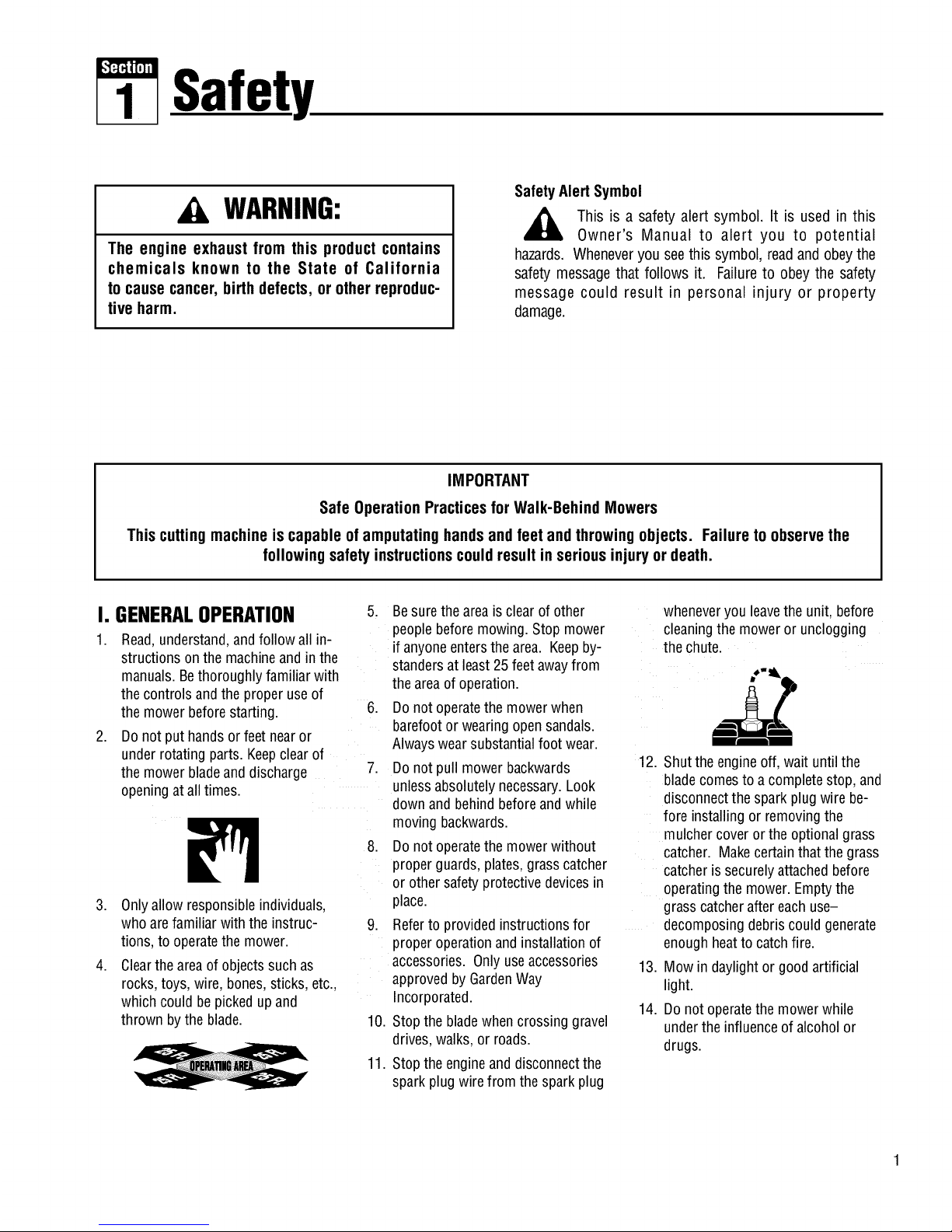
11. Stoptheengineand disconnectthe
sparkplugwirefrom the sparkplug
wheneveryou leavethe unit,before
cleaningthe moweror unclogging
the chute.
12. Shutthe engineoff, wait until the
blade comesto a completestop,and
disconnectthespark plugwire be-
fore installingor removingthe
mulchercoverorthe optionalgrass
catcher. Makecertainthatthegrass
catcherissecurelyattachedbefore
operatingthe mower.Emptythe
grass catcheraftereach use-
decomposingdebriscouldgenerate
enoughheatto catchfire.
13. Mowin daylightor goodartificial
light.
14. Donot operatethemowerwhile
underthe influenceof alcoholor
drugs.
Page 4
Section1: Safety
15.
16.
17.
Neveroperatemowerin wet grass.
Alwaysbesureof your footing; keep
a firm hold onthe handleandwalk;
never run.
Disengagethe WheelDriveLeveron
self-propelledmodelsbeforestarting
theengine.
If the unitshouldstart to vibrateab-
normally,stop the engineanddis-
connectthe sparkplug wire. Then
checkimmediatelyfor thecause.
Vibrationis generallyawarning of
trouble.
18. Alwayswearsafetygogglesorsafety
glasseswith sideshieldswhenoper-
ating mower.
19. Watchfor trafficwhen operating
near,or when crossingroadways.
20. Neverattemptto carrychildrenor
otherpassengerson themower.
Theycouldfall off and beseriously
injured,or theycould interferewith
thesafeoperationofthe mower.
21. Checkthe operationof the Operator
PresenceControlBarbeforeeach
use.Seethe MaintenanceSectionof
this manualfor instructions. If the
enginerunslongerthanthree sec-
ondsafter the OperatorPresence
Control Baris released,the system
is not working properly. Immediately
contactyour local servicedealeror
thefactory TechnicalService
Departmentfor instructions. Donot
usethe moweruntilthe mechanism
is repaired.
22. Themoweris equippedwith a safety
dischargechute,comeswith special
mulchercovers,andoffersan op-
tionalgrass catcher. Thesafetydis-
chargechute must beworking prop-
erly atalltimes. Neverattemptto
disconnectorotherwisecausethis
dischargechuteto ceaseworking. If
used,mulchercoveror grass
catcherattachmentmust beinstalled
properlyandfunction correctly. Do
not useyour equipmentotherwise.
23. Neverruntheenginein an enclosed
area.Engineexhaustcontainscarbon
monoxide,adeadlygasthat is odor-
less,colorless,andtasteless.Always
runtheengineoutdoorsand make
surethereisadequateventilation.
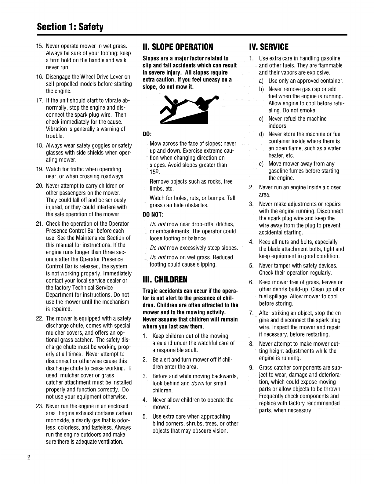
II. SLOPEOPERATION IV.SERVICE
Slopesarea majorfactorrelatedto
slipandfall accidentswhichcanresult
in severeinjury. All slopesrequire
extracaution.Ifyoufeel uneasyona
slope,donotmowit.
DO:
Mow acrossthefaceof slopes;never
upanddown. Exerciseextremecau-
tion whenchangingdirection on
slopes.Avoid slopesgreaterthan
150.
Removeobjectssuch asrocks,tree
limbs,etc.
Watchfor holes,ruts, or bumps.Tall
grass canhideobstacles.
DONOT:
1. Useextracare in handlinggasoline
andotherfuels.Theyareflammable
andtheir vaporsare explosive.
a) Useonlyan approvedcontainer.
b) Neverremovegascap or add
fuelwhentheengineis running.
Allowengineto coolbeforerefu-
eling.Donot smoke.
c) Neverrefuelthe machine
indoors.
d) Neverstore the machineor fuel
containerinsidewherethereis
an openflame,such asawater
heater,etc.
e) Movemowerawayfrom any
gasolinefumes beforestarting
theengine.
2. Neverrunan engineinside aclosed
area.
III. CHILDREN
Tragicaccidentscanoccuriftheopera-
torisnotalerttothe presenceofchil-
dren.Childrenare oftenattractedtothe
mowerandtothe mowingactivity.
Neverassumethatchildrenwill remain
whereyoulastsawthem.
1. Keepchildren out ofthe mowing
areaand underthewatchful careof
a responsibleadult.
Bealertandturn moweroff if chil-
drenenterthearea.
.
3.
4. Neverallow childrento operatethe
mower.
5. Useextracarewhenapproaching
blind corners,shrubs,trees,or other
objectsthat mayobscurevision.
Beforeandwhile movingbackwards,
look behindanddown for small
children.
3. Nevermakeadjustmentsorrepairs
with theenginerunning. Disconnect
thesparkplug wire and keepthe
wireawayfrom the plugto prevent
accidentalstarting.
Keepall nuts andbolts,especially
thebladeattachmentbolts,tight and
keepequipmentin goodcondition.
Nevertamperwithsafety devices.
Checktheir operationregularly.
6. Keepmowerfree of grass,leavesor
otherdebrisbuild-up.Cleanupoil or
fuelspillage.Allow mowerto cool
beforestoring.
7. Afterstriking an object,stopthe en-
gineanddisconnectthesparkplug
wire. Inspectthe mowerandrepair,
if necessary,before restarting.
8. Neverattemptto makemowercut-
ting heightadjustmentswhilethe
engineis running.
9. Grasscatchercomponentsaresub-
jectto wear, damageanddeteriora-
tion, which couldexposemoving
parts or allowobjectsto bethrown.
Frequentlycheckcomponentsand
replacewith factoryrecommended
parts,whennecessary.
Donot mowneardrop-offs,ditches,
or embankments.Theoperatorcould
loosefooting or balance.
4.
Donot mowexcessivelysteepslopes.
Donot mowon wet grass.Reduced
footing could causeslipping. 5.
Page 5
Section1: Safety
13.
10. Mowerbladesaresharpandcan
cut.Wrapthe bladeorwear gloves,
and useextracautionwhenservic-
ing them.
11. Donotchangetheenginegovernor
settingor overspeedthe engine.
12. Donottouch enginepartswhich
may behotfrom operation.Allow
partsto cool completelybeforein-
specting,cleaningor repairingthe
mower.
14.
Toaccessthe undersideof the
mower,tip the mowerrearward.Do
nottip the mowerforwardor onei-
ther of its sides, unlessspecifically
advisedto dosoin this manual.
Maintainorreplacesafetyand in-
structionaldecals. Referto the sep-
aratePartsCatalogfor replacement
decalinformation.
15. Forunitsequippedwith electric
start:
a) Batteriesproduceexplosive
gases.Keepsparks,flame,
cigarettes,etc.,away. Ventilate
theareawhenchargingthe bat-
tery.Donotchargethebatteryin
anairtightspace.
b) Donot useabatterycharger
otherthan the oneprovidedwith
the mower.
c) Thebatterycontainstoxic mate-
rials. Donot damagethe battery
case.If the caseis brokenor
damaged,avoidcontactwiththe
batterycontents.
d) Properlydisposeof adamaged
or worn outbattery.Checkwith
localauthorities for properdis-
posalmethods.
e) Donot short circuit the battery.
Severeburnsandfire can result.
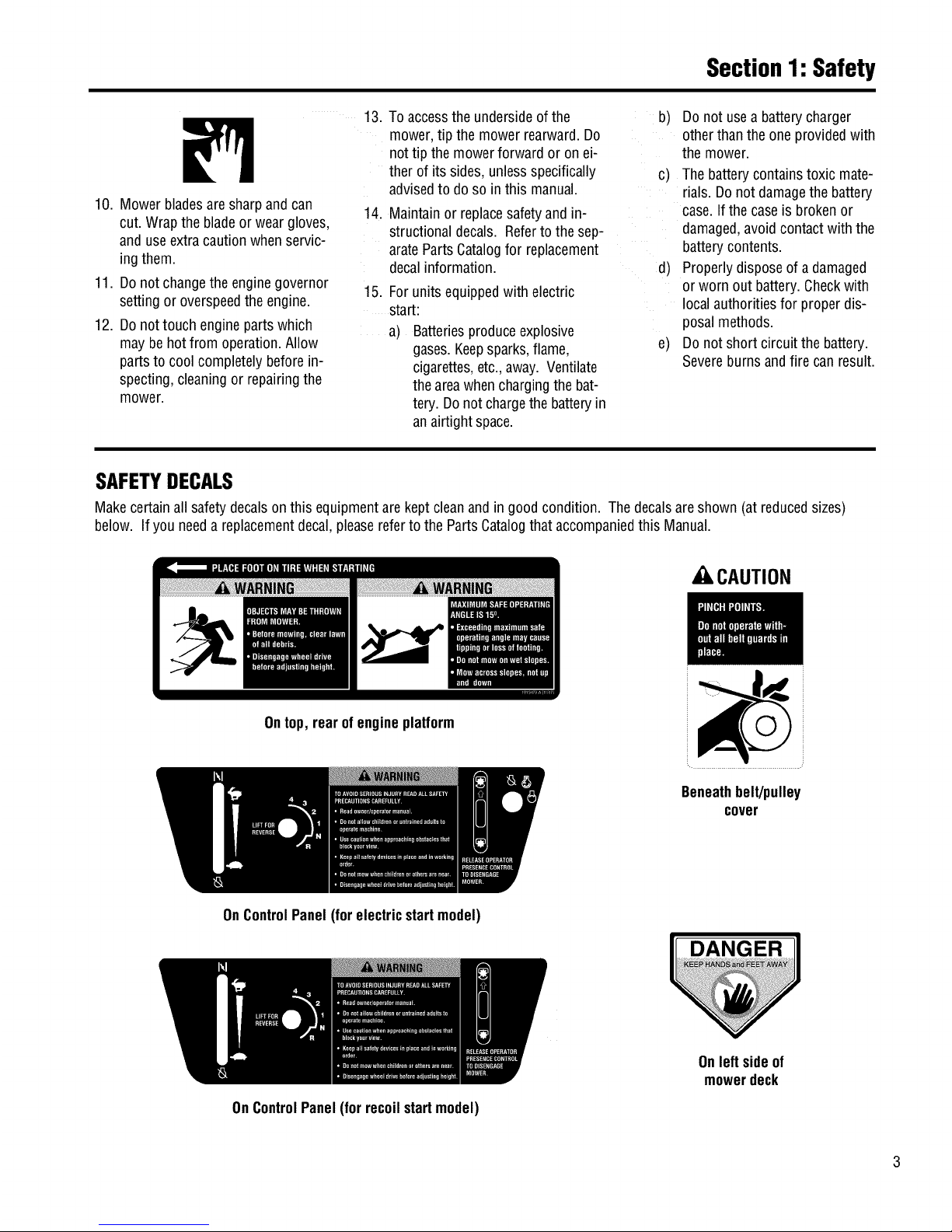
SAFETYDECALS
Makecertainallsafetydecalsonthis equipmentarekeptcleanandin good condition. Thedecalsareshown (at reducedsizes)
below. If you needareplacementdecal,pleasereferto the PartsCatalogthat accompaniedthis Manual.
Ontop, rearof engineplatform
,CAUTION
Beneathbelt/pulley
cover
OnControlPanel(for electricstartmodel)
OnControlPanel(for recoilstartmodel)
Onleft sideof
mowerdeck
Page 6
Assembly
To preventpersonalinjuryor property
damage, do not attempt to start the
engine until all assembly steps are
complete and you have read and
understand the safety, controls and
operatinginstructionsinthismanual.
INTRODUCTION
Pleasecarefullyfollow theseassembly
stepsto properlyprepareyour machine
for use. Werecommendthatyou read
this Sectionin its entirety beforebegin-
ningassembly.
NOTE:All referencesto left, right,front
and rearof the machinearedetermined
bystandingbehindthehandlebarsand
facingthe direction offorward travel.
INSPECTIONAFTERDELIVERY
Inspectthe shipping crateand machine
immediatelyafterdelivery. Makesure
neitherthe carton northe contentshave
beendamaged.
If youfind or suspectanydamage,con-
tact thecarrier(trucking company)
immediately. Informthem of thespecific
damageandthatyou wish to filea claim.
To protectyour rights, besure to put
this in writing to thecarrier within 15
days. Thecarrierwill letyou knowhow
to proceedwith your claim. Pleaseletus
knowif you needanyassistance.
TOOLS/MATERIALSNEEDED:
• WireCutter
• 7/16" Wrench
• 3/8" Wrench
• Two 1/2" Wrenches
• Scissorsor PenKnife
• Needle-nosePliers
• Motor Oil(seeStep 5)
• TireGauge
ASSEMBLYSTEPS
IMPORTANT:MOTOROIL MUSTBE
ADDEDTOTHEENGINEBEFOREIT IS
STARTED.FOLLOWINSTRUCTIONSIN
THIS"ASSEMBLY"SECTION.
STEP1: Unpacking Mower
NOTE:LEFTand RIGHTsidesofthe unit
areasviewedfrom the operator'sposi-
tion behindthehandlebars.
1. Cutmetalstraps, if present,securing
unitto pallet.Leaveuniton palletduring
assembly(tosafelyremoveunit from
pallet,wait untilyou havecompletedas-
semblysteps1-4).
2. Removeanyprotectivepackaging
from aroundthe handlebars.Cutthe
plastictie strapsholdingthefour long
control rodsto the handlebars.Donot
removethe two long handlebarstruts
that areattachedto thetop of the
handlebars.
STEP2: Attach Handlebars
to EngineDeck
1. Removetheplasticties holdingthe
wheeldriverod (F,Figure2-7) to the left
handlebarandthe bladedrive rod (C,
Figure2-7)to the right handlebar.Put
the rodsaside.
NOTE:Fourscrews(D, Figure2-2)are
usedto connectthe handlebarsto the
enginedeck. At thefactory, these
screwsarethreadedinto lock nuts
weldedto the backsidesofthe deck.
2. Removeandsavethe four 5/16"-18
x 3/4"screwsmentionedinthe NOTE
above.
3. Fromthe front ofthe unit,tilt the
right-sidehandlebarupoverthe air
cleanercoverandlift the otherhandlebar
upward. Rotatethe handlebarsoverthe
engineandpositionthe handlebarends
(E,Figure2-2)againstthesidesof the
enginedeck.
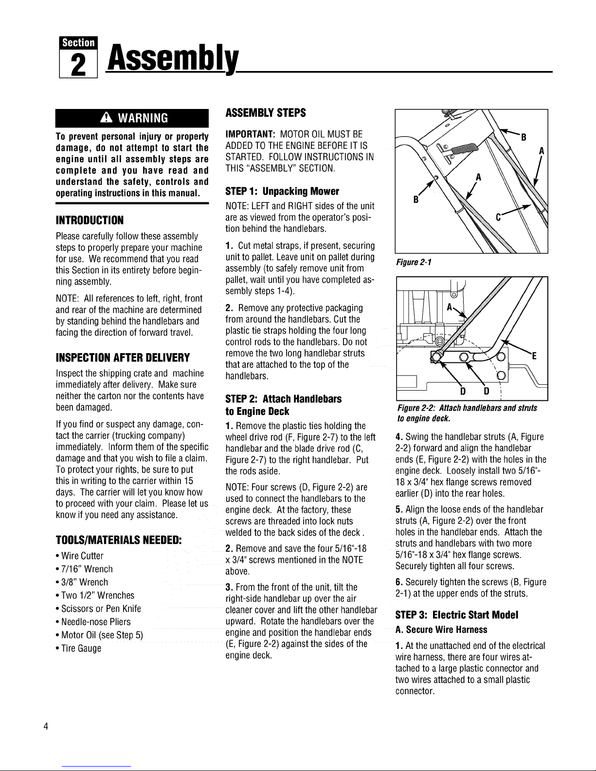
Figure2-1
E
_ r D D
i
Figure2-2:Attachhandlebarsandstruts
toenginedeck.
4. Swingthe handlebarstruts (A,Figure
2-2) forward andalign thehandlebar
ends(E,Figure2-2) withthe holesin the
enginedeck. Looselyinstall two5/16"-
18x 3/4"hexflange screwsremoved
earlier(D) into the rearholes.
5. Alignthe looseends ofthe handlebar
struts (A,Figure2-2) overthe front
holes inthehandlebarends. Attachthe
struts and handlebarswithtwo more
5/16"-18x3/4" hexflangescrews.
Securelytightenallfour screws.
6. Securelytightenthe screws(B, Figure
2-1) atthe upperendsof the struts.
STEP3: Electric Start Model
A. SecureWireHarness
1. Atthe unattachedendof theelectrical
wire harness,there arefour wiresat-
tachedto a largeplasticconnectorand
two wires attachedto a smallplastic
connector.
Page 7
Section2: Assembly
2. Plugthelargeconnectorintothe bot-
tom of theignition keyswitchthat islo-
catedonthe undersideofthe handlebar
console(not pictured).
3. Usetwo cabletiesto securethewire
harnessto the right handlebarandaway
from any movingparts. Placethe tiesan
equaldistanceapart.
B. AttachWire Leadsto Battery
1. Thebatteryis locatedatthe rear,
right-side ofthe enginedeck.
2. Atthelower end of the electrical
wiring harness,locatea redwire lead
andablackwirelead.
• Plugterminal on red(positive)wire into
redterminal (U, Figure2-3)on battery.
• Plugterminalon black(negative)wire
into blackterminal(V).
3. Ifapplicable,attachwire harnessto
enginedeckusingJ-clips (W, Figure
2-4) asshown. BendJ-clips overto
secure.
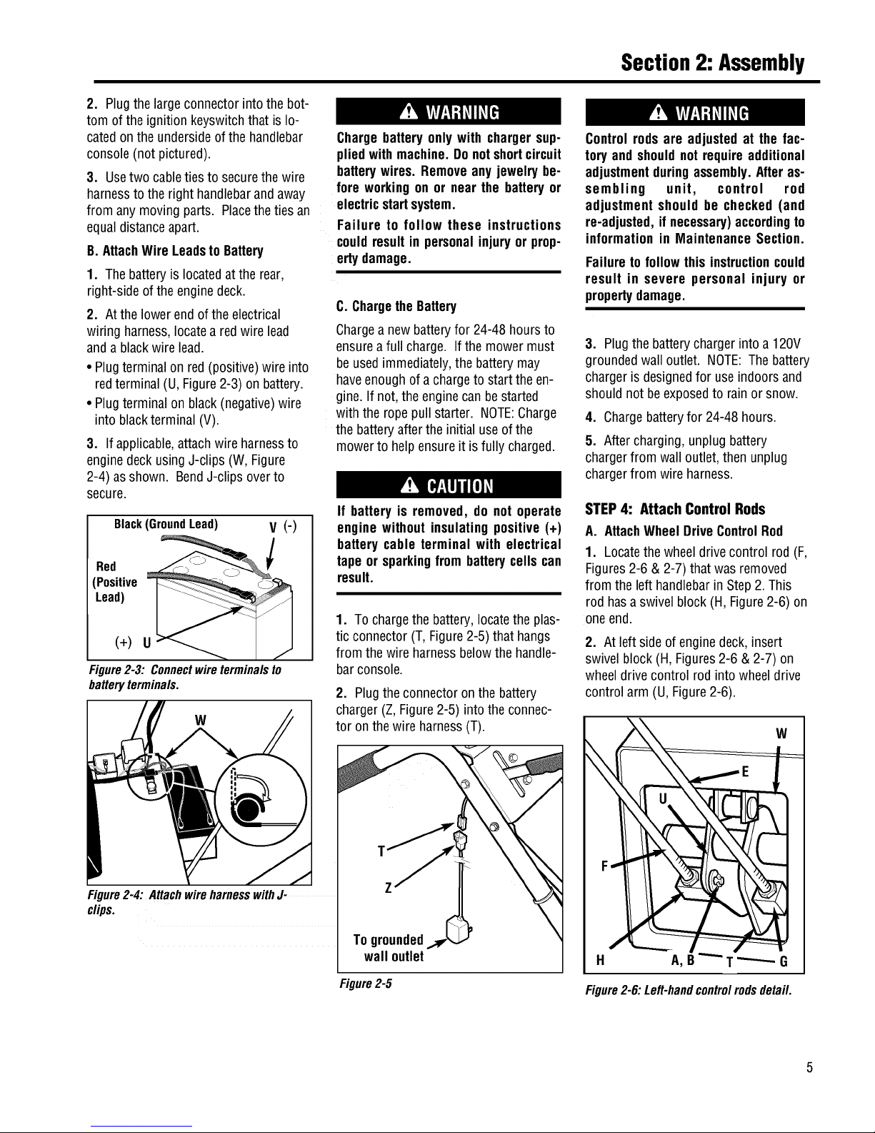
Black(GroundLead) V (-)
Red
(Positive
Lead)
(+) U
Figure2-3: Connectwireterminalsto
batteryterminals.
W
Figure2-4: AttachwireharnesswithJ-
clips.
Chargebatteryonlywith chargersup-
pliedwith machine.Donotshortcircuit
batterywires. Removeany jewelry be-
fore workingon ornear the batteryor
electricstartsystem.
Failure to follow these instructions
couldresultin personalinjuryor prop-
ertydamage.
C. Chargethe Battery
Chargeanewbatteryfor 24-48 hoursto
ensureafull charge. If the mowermust
be usedimmediately,the batterymay
haveenoughof a chargeto starttheen-
gine.If not, theenginecanbestarted
with the ropepullstarter. NOTE:Charge
the batteryafter theinitial use ofthe
mowerto helpensure it isfully charged.
If batteryis removed, do not operate
enginewithout insulatingpositive (+)
battery cable terminal with electrical
tape orsparkingfrom batterycells can
result.
1. To chargethe battery,locatethe plas-
tic connector(T, Figure2-5) thathangs
from thewire harnessbelowthe handle-
barconsole.
2. Plugtheconnectoron the battery
charger(Z, Figure2-5) intothe connec-
tor onthewireharness(T).
T
Z
To grounded
wall outlet
Figure2-5
Controlrodsare adjusted at the fac-
tory andshouldnot requireadditional
adjustmentduringassembly.Afteras-
sembling unit, control rod
adjustment should be checked (and
re-adjusted,ifnecessary)accordingto
informationin Maintenance Section.
Failureto follow this instructioncould
result in severe personal injury or
propertydamage.
3. Plugthebatterycharger intoa 120V
groundedwall outlet. NOTE:The battery
chargeris designedfor useindoors and
should not beexposedto rainor snow.
4. Chargebatteryfor 24-48hours.
5. Aftercharging,unplugbattery
chargerfrom wall outlet,then unplug
chargerfrom wire harness.
STEP4: Attach Control Rods
A. AttachWheelDriveControlRod
1. Locatethe wheeldrivecontrol rod(F,
Figures2-6 & 2-7) that wasremoved
from theleft handlebarin Step2.This
rod hasaswivel block (H, Figure2-6) on
oneend.
2. At left sideofenginedeck,insert
swivel block(H,Figures2-6 & 2-7) on
wheeldrivecontrol rod into wheeldrive
control arm (U,Figure2-6).
W
H A,B _G
Figure2-6:Left-handcontrolrodsdetail.
Page 8
Section2: Assembly
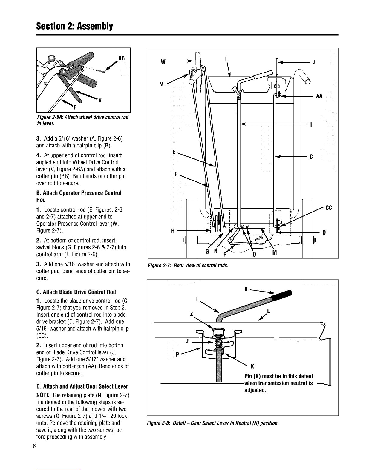
BB
Figure2-6A:Attachwheeldrivecontrolrod
tolever.
3. Adda5/16" washer(A,Figure2-6)
andattachwith a hairpinclip (B).
4. At upperend ofcontrol rod,insert
angledend intoWheel DriveControl
lever(V,Figure2-6A)andattachwith a
cotterpin (BB). Bendendsof cotter pin
overrod to secure.
B. AttachOperatorPresenceControl
Rod
1. Locatecontrol rod (E,Figures.2-6
and2-7) attachedat upperendto
OperatorPresenceControllever(W,
Figure2-7).
2. At bottom ofcontrol rod,insert
swivelblock (G, Figures2-6 &2-7) into
control arm (T,Figure2-6).
3. Addone5/16"washerandattachwith
cotterpin. Bendendsof cotter pinto se-
cure.
C. AttachBladeDriveControlRod
1. Locatethe bladedrive control rod (C,
Figure2-7) thatyou removedin Step2.
Insertoneend of control rod into blade
drivebracket(D,Figure2-7). Add one
5/16"washerandattachwith hairpin clip
(cc).
2. Insertupperend of rod into bottom
endof BladeDriveControllever(J,
Figure2-7). Add one5/16"washerand
attachwith cotter pin (AA). Bendendsof
cotterpin to secure.
D. AttachandAdjustGearSelectLever
NOTE:The retainingplate (N, Figure2-7)
mentionedinthe following steps isse-
curedto the rearofthe mowerwith two
screws(0, Figure2-7) and 1/4"-20 lock-
nuts. Removethe retainingplateand
saveit, alongwith thetwo screws,be-
foreproceedingwithassembly.
6
V
F
G N
Figure2-7:Rearviewofcontrolrods.
0
M
C
f
2
Figure2-8: Detail- GearSelectLeverin Neutral(N) position.
K
Pin(K)mustbeinthisdetent
whentransmissionneutralis --_
adjusted.
Page 9
Section2: Assembly
1. Holdlowerpart of gearselectlever
(I, Figure2-9) againstbracket(M).
Position retainingplate (N), removed
earlier,as shown in Figure2-9(plate
belowbracket). Secureplatewith two
1/4"-20x 1/2"screws (0) and 1/4"-20
Iocknuts.
6. Slidegrip(B, Figure2-8) backonto
gearselectlever(I).
7. Rotategearselectlever(I, Figures2-
8 & 2-9) clockwise untilspur (K - short
rod) ongearselectrod stops in theneu-
tral positiondetenton theshift pattern
quadrant(Figure2-8).
8. At bottom ofcontrol rod,threadshift
link (P,Figure2-9) partiallyinto ball-
joint (Y).
9. Moveshift arm (X,Figure2-9) from
sideto sideas necessaryinto each
transmissiongeardetent until transmis-
sion isin neutral.
NOTE:Movingshift arm(X) alltheway
tothe left,andthen onenotch backto
theright, should puttransmissioninto
neutral.Whentransmissionis in neutral,
unitwill movefreelywhenpushedwhile
holdingtheOperatorPresenceControl
lever(W, Figure2-7) down.Iftransmis-
sionis NOTin neutral,therewill bea
slight dragon thewheelswhen pushing
unit.
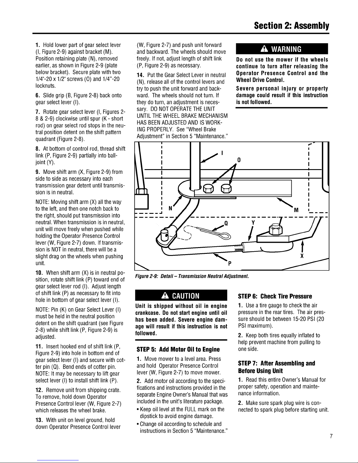
10. Whenshift arm (X)is in neutral po-
sition, rotateshift link (P)towardend of
gearselectleverrod (I). Adjustlength
of shift link (P) asnecessaryto fit into
hole in bottomof gearselectlever(I).
NOTE:Pin(K) on GearSelectLever(I)
must beheldinthe neutralposition
detentonthe shift quadrant(see Figure
2-8) whileshift link(P, Figure2-9) is
adjusted.
11. Inserthookedendof shift link (P,
Figure2-9) into holein bottomend of
gearselectlever(I) andsecurewith cot-
ter pin(Q). Bendendsof cotterpin.
NOTE:Itmay benecessaryto lift gear
selectlever (I) to install shift link (P).
12. Removeunitfrom shippingcrate.
Toremove,holddown Operator
PresenceControllever(W, Figure2-7)
which releasesthe wheelbrake.
13. Withunit onlevelground,hold
downOperatorPresenceControllever
(W, Figure2-7)andpush unitforward
and backward.Thewheelsshould move
freely. Ifnot, adjustlengthof shift link
(P,Figure2-9)as necessary.
14. Putthe GearSelectLeverin neutral
(N), releaseall ofthe control leversand
try to pushtheunit forwardand back-
ward. Thewheelsshouldnotturn. If
they do turn, an adjustmentis neces-
sary. DONOTOPERATETHEUNIT
UNTILTHEWHEELBRAKEMECHANISM
HASBEENADJUSTEDANDISWORK-
INGPROPERLY.See"WheelBrake
Adjustment"in Section5 "Maintenance."
Do not use the mower if the wheels
continue to turn after releasing the
Operator Presence Control and the
WheelDriveControl.
Severe personal injury or property
damagecouldresult if this instruction
isnotfollowed.
: ;° I
I .,I I I
I I
I / o I I
o4
,
I I
I I
J.
Figure2-9:Detail- TransmissionNeutralAdjustment.
Unit is shippedwithout oil in engine
crankcase.Donotstart engineuntil oil
has beenadded. Severeengine dam-
age will result it thisinstructionis not
followed.
STEP5: Add Motor Oil to Engine
1. Movemowerto a levelarea.Press
and hold OperatorPresenceControl
lever(W,Figure2-7)to movemower.
2. Addmotoroil accordingtothe speci-
ficationsandinstructionsprovidedinthe
separateEngineOwner'sManualthat was
includedintheunit's literaturepackage.
• Keepoil levelatthe FULLmarkon the
dipstick to avoidenginedamage.
• Changeoilaccordingtoscheduleand
instructionsin Section5 "Maintenance."
STEP6: Check Tire Pressure
1. Useatire gaugeto checkthe air
pressureinthe reartires. Theair pres-
sureshould bebetween15-20PSI(20
PSImaximum).
2. Keepbothtires equallyinflatedto
help preventmachinefrom pulling to
oneside.
STEP7: After Assembling and
Before UsingUnit
1. Readthis entire Owner'sManualfor
propersafety,operationand mainte-
nanceinformation.
2. Makesurespark plug wire is con-
nectedto spark plugbeforestarting unit.
Page 10
FeaturesandControls
IMPORTANT: THE MOWER IS
Before operating mower, be sure to
read all safety, controlsand operating
instructions in this Manual and on
decalslocatedonmachine.
Severe personal injury or property
damage couldresultit this instruction
isnotfollowed.
EQUIPPED WITH A BLADE-BRAKE-
CLUTCHCONTROLSYSTEMWHICH IS
DESIGNED TO STOP THE MOWER
BLADESWITHIN THREE(3) SECONDS
AFTERRELEASEOF THE OPERATOR
PRESENCECONTROL. THIS SYSTEM
WILL STOPTHEBLADESBUTNOTTHE
ENGINE.THEREFORE,YOUCANDISEN-
GAGETHE BLADEDRIVEAT ANYTIME
WITHOUT HAVING TO STOP AND
RESTARTTHEENGINE.THIS FEATURE
IS PARTICULARLYUSEFULWHENYOU
NEEDTO CROSSGRAVELDRIVESOR
ROUGHTERRAIN AND YOU DO NOT
WANT THE SPINNING BLADES
TO STRIKE STONES OR HIDDEN
OBSTACLES.
MOWERFEATURESAND
CONTROLS
This sectiondescribesthevarious
featuresand controls on the unit. Refer
to the nextsection"Operation"for
detailedoperatinginstructions. Also,
readthe separateEngineOwner's
Manualfor a detailedexplanationofthe
proper useof the enginecontrols.
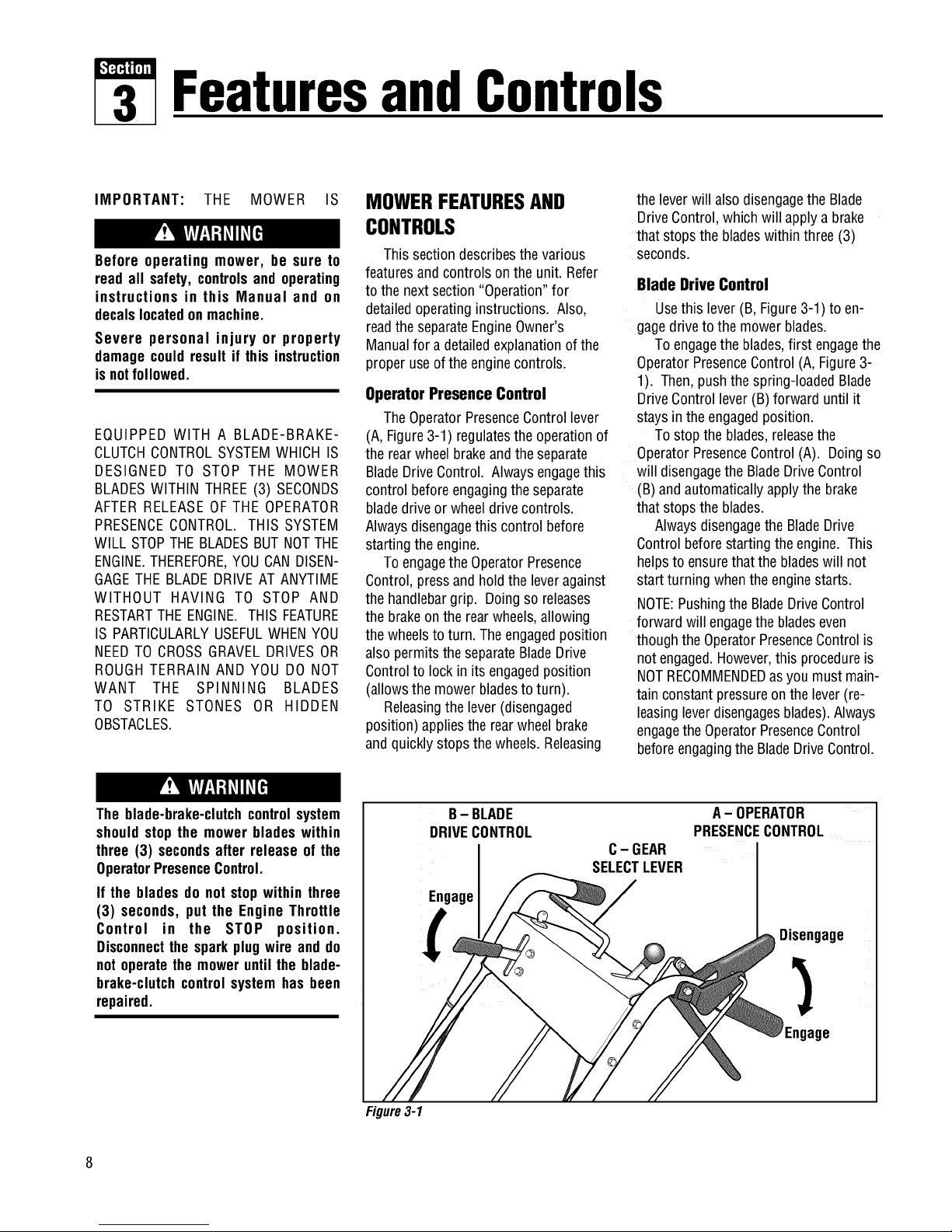
Operator Presence Control
TheOperatorPresenceControllever
(A, Figure3-1) regulatesthe operationof
the rearwheelbrakeandtheseparate
BladeDriveControl. Alwaysengagethis
control beforeengagingthe separate
bladedriveor wheeldrivecontrols.
Alwaysdisengagethis control before
startingtheengine.
ToengagetheOperatorPresence
Control,pressand holdthe leveragainst
the handlebargrip. Doingso releases
the brakeon therearwheels,allowing
the wheelsto turn. The engagedposition
alsopermitstheseparateBladeDrive
Controlto lock inits engagedposition
(allowsthe mowerbladesto turn).
Releasingthe lever(disengaged
position) appliesthe rearwheelbrake
andquicklystopsthe wheels.Releasing
the leverwill alsodisengagethe Blade
DriveControl,which will applya brake
that stopsthe bladeswithinthree (3)
seconds.
Blade Drive Control
Usethis lever(B, Figure3-1)to en-
gagedriveto themower blades.
Toengagetheblades,first engagethe
OperatorPresenceControl(A,Figure3-
1). Then,push thespring-loadedBlade
DriveControllever(B)forward until it
stays in theengagedposition.
Tostop the blades,releasethe
OperatorPresenceControl(A). Doingso
will disengagethe BladeDriveControl
(B) andautomaticallyapplythe brake
that stopsthe blades.
AlwaysdisengagetheBladeDrive
Controlbeforestartingtheengine. This
helpsto ensurethatthe bladeswill not
start turning whentheenginestarts.
NOTE:Pushingthe BladeDriveControl
forward will engagethebladeseven
thoughtheOperatorPresenceControlis
notengaged.However,this procedureis
NOTRECOMMENDEDasyou must main-
tainconstantpressureon thelever(re-
leasingleverdisengagesblades).Always
engagethe OperatorPresenceControl
beforeengagingtheBladeDriveControl.
The blade-brake-clutchcontrolsystem
shouldstop the mower bladeswithin
three (3) secondsafter release of the
OperatorPresenceControl.
If the bladesdo notstopwithin three
(3) seconds, put the Engine Throttle
Control in the STOP position.
Disconnectthe sparkplugwire and do
not operatethe moweruntil the blade-
brake-clutchcontrol systemhas been
repaired.
B- BLADE
DRIVECONTROL
Engage
C- GEAR
SELECTLEVER
A-OPERATOR
PRESENCECONTROL
Disengage
Engage
Figure3-1
Page 11
Section3: FeaturesandControls
Operating Symbols Varioussymbolsareusedon the mowerto indicatecontrol settings(your modelmaynot haveall of the
symbols).Thesesymbolsareshown belowwith a descriptionof their meaning.
ENGINE ENGINE ENGINE
FAST SLOW CHOKE ENGAGE DISENGAGE STOP START RUN
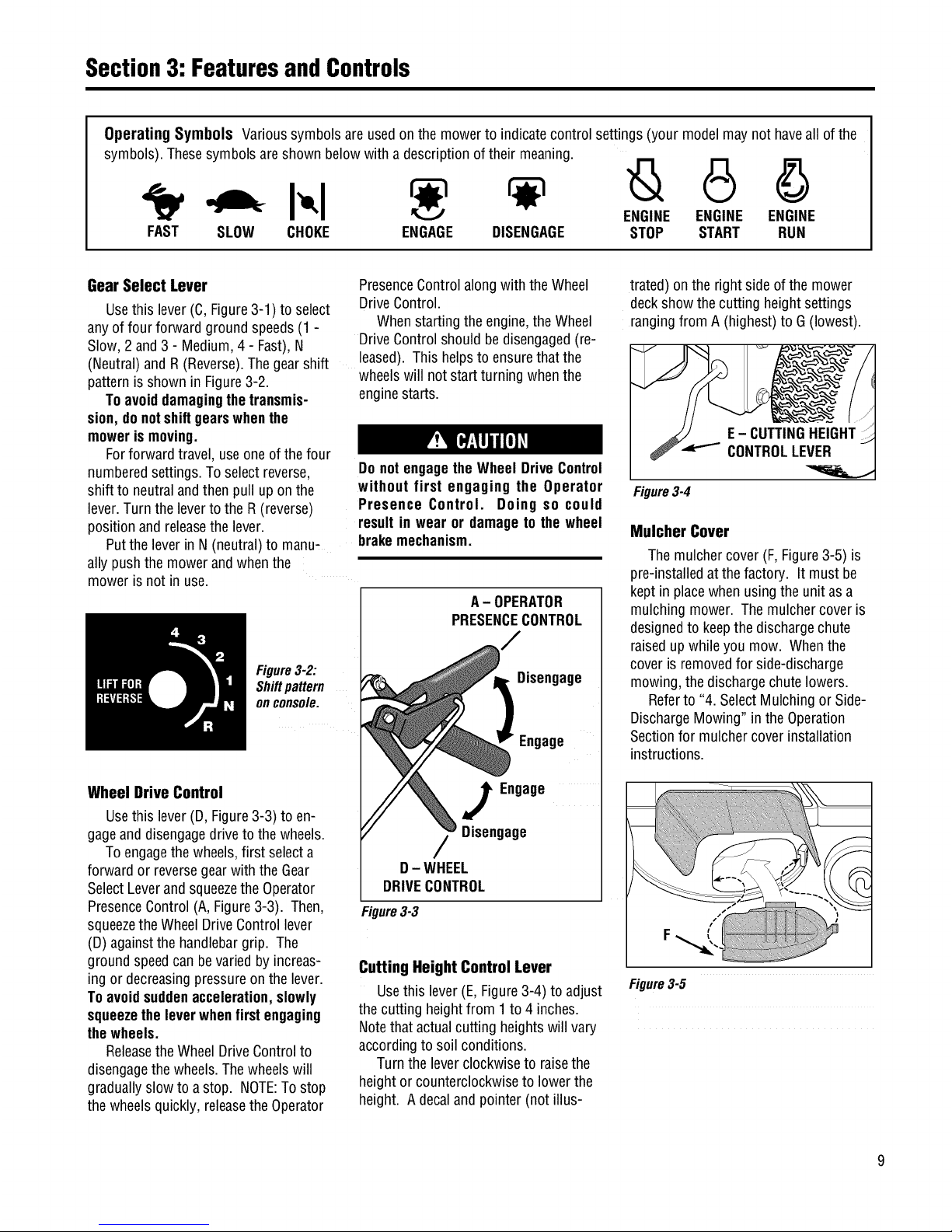
Gear Select Lever
Usethislever(C,Figure3-1)to select
anyof four forwardgroundspeeds(1 -
Slow,2and3 - Medium,4 - Fast),N
(Neutral)and R(Reverse).Thegearshift
patternisshown in Figure3-2.
Toavoiddamagingthetransmis-
sion, donotshiftgearswhenthe
mowerismoving.
Forforward travel,useoneof thefour
numberedsettings.Toselectreverse,
shift to neutralandthenpull upon the
lever.Turnthe leverto theR (reverse)
positionandreleasethe lever.
Putthe leverin N(neutral)to manu-
ally pushthe mowerandwhenthe
moweris not in use.
PresenceControlalong with the Wheel
DriveControl.
Whenstarting theengine,theWheel
DriveControlshouldbedisengaged(re-
leased).Thishelpsto ensurethatthe
wheelswill not startturning whenthe
enginestarts.
Do notengagetheWheel DriveControl
without first engaging the Operator
Presence Control. Doing so could
resultin wear or damageto the wheel
brakemechanism.
Figure3-2:
Shiftpattern
onconsole.
A- OPERATOR
PRESENCECONTROL
Disengage
Engage
Wheel Drive Control
Usethislever(D, Figure3-3) to en-
gageanddisengagedrive to thewheels.
Toengagethewheels,first selecta
forward or reversegearwith theGear
SelectLeverandsqueezetheOperator
PresenceControl(A,Figure3-3). Then,
squeezetheWheelDriveControllever
(D)againstthe handlebargrip. The
ground speedcan bevariedby increas-
ing or decreasingpressureon the lever.
Toavoidsuddenacceleration,slowly
squeezetheleverwhenfirstengaging
thewheels.
Releasethe WheelDriveControlto
disengagethewheels.Thewheelswill
graduallyslow to a stop. NOTE:Tostop
the wheelsquickly,releasethe Operator
J Engage
Disengage
D- WHEEL
DRIVECONTROL
Figure3-3
Cutting HeightControl Lever
Usethis lever(E, Figure3-4)to adjust
thecutting heightfrom 1to 4 inches.
Notethat actualcutting heightswill vary
accordingto soil conditions.
Turnthe leverclockwiseto raisethe
heightor counterclockwiseto lowerthe
height. A decalandpointer (notillus-
trated) onthe right sideofthe mower
deckshowthecutting heightsettings
rangingfrom A (highest)to G(lowest).
Figure3-4
Mulcher Cover
Themulchercover (F,Figure3-5) is
pre-installedatthe factory. It must be
kept in placewhenusingthe unit asa
mulchingmower. The mulchercoveris
designedto keepthe dischargechute
raisedupwhileyou mow. Whenthe
cover isremovedfor side-discharge
mowing,the dischargechutelowers.
Referto "4. SelectMulching or Side-
DischargeMowing"in the Operation
Sectionfor mulchercoverinstallation
instructions.
Figure3-5
Page 12
Section3: FeaturesandControls
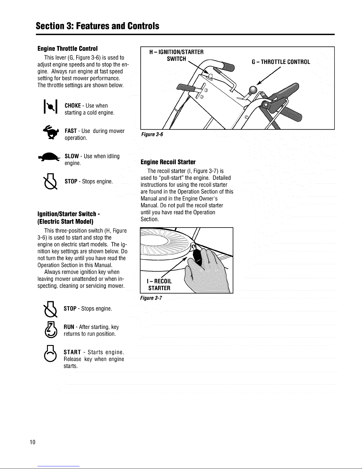
Engine Throttle Control
This lever(G,Figure3-6) is usedto
adjust enginespeedsandto stopthe en-
gine. Alwaysrunengineat fastspeed
settingfor bestmowerperformance.
Thethrottlesettings areshown below.
H- IGNITION/STARTER
SWITCH
G- THROTTLECONTROL
J
I_1 CHOKE-Usewhen
startinga cold engine.
FAST- Use during mower
operation.
Figure3-6
_._ SLOW- Usewhenidling
engine.
STOP- Stopsengine.
Ignition/Starter Switch -
(Electric Start Model)
Thisthree-positionswitch (H, Figure
3-6) is usedto startand stop the
engineonelectricstart models. Theig-
nitionkeysettings areshown below.Do
notturn the keyuntilyou havereadthe
OperationSectioninthis Manual.
Alwaysremoveignition keywhen
leavingmower unattendedor when n-
specting,cleaningor servicing mower.
Engine Recoil Starter
Therecoilstarter (I, Figure3-7) is
usedto "pull-start" the engine. Detailed
instructionsfor usingtherecoil starter
arefound in theOperationSectionof this
Manualandin the EngineOwner's
Manual.Donot pull therecoil starter
untilyou havereadthe Operation
Section.
I - RECOIL
STARTER
STOP- Stopsengine.
RUN- Afterstarting,key
returnsto run position.
Figure3-7
START - Starts engine.
Releasekey when engine
starts.
10
Page 13

Operation
Before operating mower, be sure to
read all safety, controlsand operating
instructions in this Manual and on
decalslocatedonmachine.
Severe personal injury or property
damage couldresultif this instruction
isnotfollowed.
BEFOREOPERATINGMOWER
1. Pre-OperaUon Checklist
With the sparkplugwire disconnected
from thespark plug,performthefollow-
ing checksandservicesbeforeeachuse:
1. ReviewSection1: "Safety"andSection
3, "FeaturesandControls"in this man-
ual. Readthe separateEngineOwner's
Manualprovidedwith theunit.
2.Checkunitfor looseor missinghard-
ware.Tightenorreplaceasneeded.
3. Withthe uniton levelground,check
theengineoil level accordingto the
instructionsin the EngineOwner's
Manual. Theoil levelshouldbeat the
FULLmarkonthe dipstick or upto the
top ofthe oilfill holeon engineswith-
out adipstick.
4. Checkall leversfor freedomof move-
ment.Readjustorrepairasneeded
beforestarting engine.
5. Checkthat all guardsandshieldsare
in placeandproperly secured.
6. Inspecttheareato mowedandre-
moveanydebriswhich couldbe
pickedupandthrown bythe mower
blades.
7. Checkthat the mulchercoveris prop-
erlyinstalledin the dischargeopening
(seeinstructions in this Section).
Removethe mulchercoverto usethe
side-dischargemowingfeature.
8. Onelectricstart models,checkthat
all wiring connectionsarecleanand
tight.
9. Checkthe air pressurein therear
tires (15-20 PSI). Keeptires inflated
equally.
GASOLINEISHIGHLYFLAMMABLEAND
ITS VAPORSAREEXPLOSIVE.To help
preventseverepersonalinjuryor prop-
ertydamage:
• Follow gasoline safety rules in
Section1: "Safety" of thisManualand
in the separate Engine Owner's
Manual.
• Neverremovethe gasolinefill capor
add fuel when indoorsorwhen engine
is runningor still hot.Allow engineto
coolat least three (3) minutesbefore
refueling.
• Keep smokingmaterials, sparks or
flamesfar awayfromfuel tankandfuel
container.
• Store gasoline in an approvedfuel
containerandina well-ventilatedarea.
Storeit safely outof the reachof chil-
dren. Do notstore gasolinewhereva-
porscan reachan opensparkor flame
or where ignition sourcesare present
(suchas hot water or space heaters,
furnaces,clothesdryers, stoves,elec-
tric motors,etc.).
• Fill tankto 1/2"below bottomoffiller
neckto allowfor fuel expansion.Wipe
up spilled gasoline immediately and
movemowerawayfromgasolinefumes
before starting engine. Securely re-
place caps on fuel tank and fuel
container.
10.Removethefuelcap andcheckthe
levelof gasolineaccordingto the in-
structions inthe EngineOwner's
Manual.Cleanaroundfuel fill area
beforeremovingfuelcap. Donot
checkfuel levelor addfuelwhile in-
doorsor if engineis runningor hot.
Allow engineto coolfor three (3)
minutes. Fillthe tankwith fresh,
cleanunleadedgasolinewitha mini-
mum octaneratingof 77. Leave1/2"
ofspacefor fuel expansion.Do not
mix oil with gasoline.Do not use
gasolinewhich contains Methanol.
SeetheEngineOwner'sManualfor
instructions andprecautionsregard-
ingthe use ofgasolinesthat are
blendedwith alcoholsor ethers
(calledoxygenatedor reformulated
gasolines). Securelyreplacecapson
fuel tankandfuel container.
11.Attach sparkplug wireto spark plug
after completingabovechecklist.
2. Set Mower Cutting Height
To avoidpersonalinjury, do notadjust
cuttingheightwhile wheels or blades
are turning. Release all handlebar
controlsandwait for all motionto stop
beforeadjustingcuttingheight.
1. Releaseall controls beforeadjusting
thecutting height.
2. Adjustthecutting heightfrom 1to 4
inchesby rotatingthe CuttingHeight
Controllever(Figure3-4)either clock-
wiseto raisethe heightor counterclock-
wiseto lowerthe height. Notethat ac-
tualcutting heightswill vary according
to grassandsoil conditions. A decaland
pointeron the rightside of themower
deckindicatestheheightsetting.
3. In heavyor tall grass,it is usually
betterto makethe first cut at ahigher
settingandthen makeasecondcutat
thedesiredheight. Inroughterrain, a
highersetting is recommendedasit will
minimizethe chancesof the bladestrik-
ing theground orhidden obstructions.
11
Page 14

Section4: Operation
3. Test Blade-Brake-Clutch
Control System
Themower isequippedwith a blade-
brake-clutchwhich is designedto stop
the mowerbladeswithin three(3)
secondsafter releaseofthe Operator
PresenceControlor the BladeDrive
Control. Nevertamperwith, or attempt
to defeatthe purposeofthis safety
device.
Thecontrol system isa mechanical
devicewhich issubject to wear.
Therefore,testthe operationofthe
blade-brake-clutchcontrol system before
eachuseofthe mower.Referto "Blade
BrakeControlTest"attheend of this
Section.
4. Select Mulching orSide-
Discharge Mowing
Beforeinstallingor removingmulching
cover, stop engine, wait for parts to
stopmoving,anddisconnectsparkplug
wire. Remove ignitionkey on electric
startmodels.
Youcanusethe mowereitheras a
mulchingmoweror asaside-discharge
mower. To usethe mulchingfeature,in-
sert themulchercover as described
below. Removethe mulchercoverto
side-dischargegrassclippings. The
mulchercover is designedto keepthe
dischargechute raisedup whilemowing.
Whenthe cover is removed,the dis-
chargechutewill loweritselffor side-
dischargemowing.
Toinstall or removemulchercover:
1. Stoptheengineand waitfor all parts
to stopmoving. Disconnectthespark
plug wirefrom thespark plug.Remove
theignition keyon electricstart models.
2. Toinstallthe cover,insertthe right-
sidetabof thecoverinto the front sup-
port bracket(A, Figure4-1). Insertthe
cover intothe dischargeopening,mak-
ing surethat theslot (B) in the left side
of thecover iscompletelyengagedinthe
rearedgeof the deckopening.
B
Figure4-1:Mulchercover
STARTINGANDSTOPPING
THEENGINE
Do not operate the engine in an
enclosed area. Engine exhaust
containscarbon monoxide, a deadly
gas that is odorless, colorless and
tasteless. Alwaysrunengineoutdoors
and make sure there is adequate
ventilation.
3. Toremovethecover, slidethecover
to the right(front of mower)to disen-
gagethe slot (B)from the mowerdeck
andthenprythe left-sideofthe cover
out andoff.
MOVINGTHEMOWERWITHOUT
ENGINEPOWER
Themowercan bemanuallypushed
or pulledbyputting the GearSelect
Lever(C,Figure4-2) in N(neutral)and
pressingandholdingthe Operator
PresenceControl(A, Figure4-2) down
againstthe handlebargrip.
To stopthewheelsatanytime.
releasetheOperatorPresenceControl.
ToStart the Engine
1. Movemowerto a levelarea.
2. Releaseall controls on mowerto pre-
ventwheelsormower bladesfrom rotat-
ing whenenginestarts.
3. MoveEngineThrottle Control(E,
Figure4-2) fully upwardto chokesetting
to starta coldengineor to fast (rabbit)
settingto starta warmengine.
Toavoidinjury:
• Keephandsand feet clear of mower
blades or other rotating parts.
• Lookbehindyouto be surethereare
no obstacles before pulling recoil
starterrope.
F-Ig
B- Blade Drive
Control
C - Gear Select Lever
E - Engine Throttle
Control
A-Operator
Presence Control
I
Figure4-2: MowerControls
D- Wheel Drive Control
12
Page 15

Section4: Operation
4. Tostartengineusing recoilstarter:
A. Standon left side (asviewedfrom
behindhandlebars)ofmachine.Be
sureyourfeet aresafelyawayfrom
the undersideof the mowerdeckand
all mowercontrolsare released.
Placeonefoot ontop of tire.
B. Graspstarterropehandle(Figure3-
7) andpull slowly until ropepulls
slightly harder.Letroperewind
slowly. Thenpull ropewitha rapid,
full arm stroke. Let ropereturn
slowly. If enginefails to startafter
threepulls, repeatinstructionsstart-
ingwith Step2 (trysetting throttle at
fast setting).
C. Whenenginestarts, operateinfast
throttle setting(movethrottle from
chokesettingto fastsetting).
5. Tostartengineusing electricstarter:
A. Standbehindthehandlebarsandre-
leaseallmowercontrols.
B.Turnignition key(F,Figure4-2)fully
clockwiseto crank engine.To avoid
damageto starter motor,do not
crank enginefor longerthanfive sec-
ondsat atime.Also, allow 15sec-
ondsbetweeneachstart attempt. If
enginefails to start afterthreeat-
tempts, repeatinstructions starting
with Step2 (trysetting throttle atfast
setting).
C. Whenenginestarts,releasekeyandit
will returnto therun (middle)posi-
tion.
D. Operateengineatfast throttle setting
(movethrottle from chokesettingto
fast setting).
NOTE:Ifthe electricstart systemisnot
functioning,theenginecanbestarted
with the recoilstarter. To do so,first put
theignition keyin the run(middle) posi-
tion. Thenfollow Steps1-4 above.
Leavethekeyinthe run positionduring
engineoperation.
ToStop the Engine
1. Releaseall mowercontrolsto stop
wheelsormower blade.
2. Movethrottlecontrol downto slow
(turtle) position. (Wheneverpossible,
graduallyreduceenginespeedbefore
stoppingengine.)
3. MoveThrottleControlall theway
downto stop position orturn ignition
key(electricstart models)fully counter-
clockwiseto stop position.
4. Onelectric start models,removethe
ignitionkey beforeleavingthemower
unattended.
ENGAGINGTHE BLADES
- Fast). Whenfirst practicingwith
the mower,putlever in No.1 setting.
Selectforward speedsaccordingto
mowingconditionsandterrain. Use
slower speedson roughterrainor
whengrass is heavyor thick. The
forward speedcan beincreasedon
smoothterrain or if thegrass cover
is light. Allowthewheelsto stop
completelybeforeshifting from one
forward speedinto another.
To avoid injuryfrom rotating blades,
keep face, hands and feet clear of
mowerbladesatall times.
To Engagethe Blades
1. Startengineasdescribedin "To Start
the Engine"instructions. Putengine
throttle infast speedsetting.
2. Pressandhold OperatorPresence
Control(A,Figure4-2)againsthandle-
bargrip.
3. SlowlypushBladeDriveControl(B,
BeforeengagingtheWheel DriveLever
for the very first time, checkthat the
neutral(N) positionon the GearSelect
Lever is properly adjusted. See
"Neutral Adjustment" in Section 5:
Maintenance for the procedure to
follow.
Failureto follow this instructioncould
result in personal injury or property
damage.
Figure4-2) fullyforward until it staysin C.
the engagedposition. The bladesare
nowrotating.
To Stop the Blades
Tostop the blades,releasetheOperator
PresenceControl.
TO ENGAGETHEWHEELS
• To avoiddamagingthetransmission,
donotshiftgearswhilein motion.
• To avoiddamagingthe wheel brake
mechanism,do notengagethe Wheel
DriveControlwithoutfirst engagingthe
OperatorPresenceControl.
1. Start engineasdescribedin "To
Startthe Engine"instructions.
2. FORFORWARDTRAVEL:
Tostartthe wheels,slowlysqueeze
theWheelDriveControl(D,Figure4-
2). Theharderyou squeeze,the
fasterthewheelswill turn. Toavoid
suddenacceleration,slowlysqueeze
the lever.
D.TOSTOPTHEWHEELS:
• Tostopdrivepowertothewheels,
releasetheWheelDriveControl. The
wheelswillgraduallyslowto astop.
• Toquickly stop thewheels, release
boththe WheelDriveControland
theOperatorPresenceControl.
3. FORREVERSETRAVEL:
Toavoidinjuryorpropertydamage:
• Look behind the mower before
andduringreverseoperation.
• Stopthemowerbladesbeforeeperat-
ingin reverse.
A. Pressand holdOperatorPresence
Control (A,Figure4-2) againsthan-
dlebargrip.
B. Putthe GearSelectLever(C,Figure
4-2) intoone ofthe numberedset-
tings (1 - Slow,2 and3 - Medium,4
A. Stopthe mowerbladesandwheelsby
releasingtheOperatorPresence
Control(A, Figure4-2).
B. Pressandhold OperatorPresence
Controlagainsthandlebargrip.
13
Page 16

Section4: Operation
C.
O.
E,
Putthe GearSelectLever(C,Figure
4-2) in R(reverse)settingbyfirst
movingleverto N(neutral). Then
pull leverup,turn it to Rposition,
and releaselever.
To startthewheels,slowlysqueeze
WheelDriveControl(D, Figure4-2).
Toavoidsuddenacceleration,slowly
squeezethe lever.
TOSTOPTHEWHEELS:
• Tostopdrivepowerto thewheels,
releasetheWheelDriveControl.The
wheelswillgraduallyslowto astop.
• Toquickly stop thewheels,release
both theWheelDriveControland
theOperatorPresenceControl.
• ReturntheGearSelectLeverto the
N (neutral)position whenyou have
completedreverseoperation. Allow
thewheelsto stopcompletelybe-
foreshifting from R(reverse)into a
forward speed.
MowWhen
LawnIsDry
Forbestresults,avoidcutting grass
whenit iswet. Wetgrasstendsto form
clumpswhich interferewith the cutting
action. Thebesttimeto mowis in the
lateafternoonor earlyeveningwhenthe
grassis usuallydry.
1
CutTop1/3 of /-_
GrassBlades __'
Cuttingmorethan 1/3 of grasslength
maycausethe grassto becomeexces-
sivelydry. Intall grass,it maybeneces-
saryto mowat a highersetting andthen
mow againat thedesiredheight. NOTE:
Thecutting heightis criticalto achieving
a well-groomedlawn. Youshouldexper-
iment with varioussettingsto find that
"just right" cutting height.
MAKINGTURNS..... _
VaryCuttingPattern
Themowerturns easily by pushing
thehandlebarsinthe oppositedirection
that youwantto turn. Thedifferential
mechanisminsidethetransaxlewill
allowtheinsideturning wheelto stop or
slow downwhile the outsideturning
wheelis poweredby the drivesystem.
Reducethewheelspeedbeforeturn-
ing the mower.Fortightturns, disen-
gagethe WheelDriveControlandmanu-
Varythe cutting patternfromweekto
weekto helppreventmatting ofthe
grass. Oneweek,mowfrom northto
south,thenextweekmowfrom eastto
west. Overlapseveralincheswhen
mowingto obtainan evenappearance.
MowingonSlopes
allypushthe mowerthroughtheturn (if
needed,putthe GearSelectLeverin
neutralsothewheelsturn freely).
MOWINGTIPSANDHINTS
Toavoidinjuryorpropertydamage:
• Before mowing, thoroughly inspect
area where mower is to be usedand
remove all stones, sticks, wires,
bones,nailsandotherforeignobjects.
• Disengage mower blades before
crossinggraveldrives, roads, or side-
walksto preventbladesfromthrowing
stonesor otherhazardousobjects.
Toavoidinjury orpropertydamage:
• Maximum safe operating angle
is150.
• Exceedingmaximum safe operating
angle may cause tipping or loss of
footing.
• Donotmowwet slopes.
• Mowacrossslopes,notupanddown.
• Exercise extreme caution when
changingdirectiononslopes.
MulchingLeaves
• Themowercanbeusedto mowfallen
leaves.Theleafparticlesfilter downinto
thelawnandprovideaddedfertilizer.
• Theleavesmustbedry in orderto be
mulched.
• Useaslowerground speedif the
leavesarenot mulchedinto fine parti-
cles.
• Ifyoumulch oakleaves(whichaddacid
tothe soil), addlimeto the lawninthe
springto reducetheacidityofthe soil.
KeepMowerBladesSharp
Forbestmowerperformance,keepthe
bladessharp. Dull bladeswill tear,
bruiseandsplit the endsof grass. See
bladesharpeninginstructions in Section
5: Maintenance.
Donot mowexcessivelysteepslopes
(seeWARNINGstatementthatfollows).
Slowdownandexerciseextremecaution
whenchanging directionon slopes.
Beforemowing on slopes,checktheen-
gine oil levelandmakesure thatthe level
is attheFULLmark. MaintainingaFULL
oil levelis particularlyimportantwhen
operatingon slopesas oil canbe drained
awayfrom vital engineparts.
CleanMowerFrequently
Cleanthe undersideofthe mowerdeck
frequentlyto removegrass build-up.
Seemowercleaninginstructionsin
Section5: Maintenance.
PrecisionTrimming
Forprecisiontrimming, usethe slow-
estgearandinch themower alongby
"feathering"the WheelDriveControl
lever. Or,disengagethe wheeldrive by
releasingtheWheelDriveControlso that
you canmanuallymaneuverthemower
(if needed,put the GearSelectLeverin
neutralso that thewheelsturn freely).
MowingDitches
If you haveto mow ditches,stop the
engineandadjustthe cuttingheightto
its highestsetting. Mow in the direction
ofthe ditch. Mow bothsidesof theditch
14
Page 17

Section4: Operation
first, and thenmow the bottom. When
mowing ditches,watchout for cans,
bottles, or otherdebris.
BLADEBRAKECONTROLTEST
Whenthe OperatorPresenceControl
is releasedduring operationofthe
mower,theenginedoesnot stop,but
thebladesshouldstop within three (3)
seconds. Thefollowingtest providesa
visualtest of whetherthe BladeBrake
ControlSystemisfunctioning. Perform
this test beforeeachuseofthe mower.
To avoid personal injury or property
damage,make sure thatthe moweris
ongrass,andthatthe testarea isclear
of foreignobjectsand bystandersbe-
fore you beginthe BladeBrakeControl
Test.
If the OperatorPresenceControlorthe
Blade Drive Controlare not adjusted
correctly,the bladesmay continueto
rotate after release of the Operator
PresenceControl. If the bladesdo not
stopwithinthree(3) secondsof release
ofthe OperatorPresenceControl,move
the EngineThrottleControlto the STOP
position, disconnect the spark plug
wire, andmovethewire awayfromthe
sparkplug. Donot operatethe mower
until the Blade Brake ControlSystem
hasbeenrepaired.
Failureto do this couldresult in per-
sonalinjuryor propertydamage.
1. Parkmower ona portion of lawn
which hasnot beenrecentlymowed.
2. Setthecutting heightso the mower
cuts 1/3 ofthe grassheight.
3. Starttheengine.
4. PresstheOperatorPresenceControl
downagainstthe handlebargrip and
pushthe BladeDriveControlfully for-
ward until it staysintheengagedposi-
tion.
5. Putthe GearSelectLeverin the No.1
setting.
6. Engagethe wheelswith the Wheel
DriveControlanddrivethe mowerfor
severalfeet. Then releasethe Operator
PresenceControl.
A.
Lookatthelawn just mowed.The
lawnshouldbecut upto the point
wherethe OperatorPresenceControl
was released.
B. Pressthe OperatorPresenceControl
againstthe handlebargrip but DO
NOTre-engagethe BladeDrive
Control. Drivethe mowerforward
for severalmorefeet. Releasethe
OperatorPresenceControlandlook
atthe lawn.Thegrassshould NOT
havebeencut. This indicatesthat
theOperatorPresenceControlhas
disengagedthe bladedrive and
stoppedtheblades.
7. Ifthe mowercutsthe grass in Step
6-B,the OperatorPresenceControlis
NOTdisengagingthe bladedrive.
Immediatelystopthe engine,discon-
nectthesparkplugwire,andmovethe
wireawayfromthesparkplug.
8. Donot usethe mower untilthe Blade
BrakeControlSystemhasbeenin-
spected,adjustedorrepairedbyanau-
thorizeddealer.
15
Page 18

Maintenance
Beforeinspecting,cleaningorservicingthemachine,shutoffengine,waitformovingpartstostop,disconnectspark
plugwireandmovewireawayfromsparkplug.Removeignitionkey(elecb'icstartmodels).
Failuretofollowtheseinstructionscanresultinseriouspersonalinjuryorpropertydamage.
Carefully read this Section on mower
and engine maintenance and service.
Performing the required maintenance
according to schedule will ensure the
proper performanceandlong lifeof your
machine.
Beforeinspecting,cleaningor servicing
the machine, shut off engine, make
surethatall movingpartshavecometo
a completestop,disconnectsparkplug
wire and move wire away from spark
plug. Removeignition key on electric
startmodels.
Failureto followtheseinstructionscan
result in personal injury or property
damage.
NOTE: All referencesto left, right,front
and rearofthe machinearedeterminedby
standingbehindthe handlebarsandfacing
thedirectionofforwardtravel.
IMPORTANT:REFERTO
MAINTENANCECHARTINTHIS
SECTIONFORA LISTINGOFREGU-
LARLYSCHEDULEDMAINTENANCE
PROCEDURES.
ENGINESERVICE
Routineengineserviceis described
below. Formore completeengineser-
vice information, referto theengine
manualprovidedwithyour machine.
Forcompleteengineservice,contactan
authorizedenginedealer.
ENGINEOIL
OIL LEVEL:With moweron level
ground,theengineoil levelmust bebe-
tweenthe"ADD"and "FULL"markson
the dipstickat all times. Checkbefore
eachuseandevery5 operatinghours.
OILCHANGE:Ona newengine,change
oil afterfirst 2 hoursof use,thenchange
oil regularlyasspecifiedon the
MaintenanceChart. Referto Engine
Owner'sManualfor oil capacity.
OILTYPE:Useclean,high qualitydeter-
gent oilhavinganA.P.I.serviceclassifi-
cation of SE,SForSG. Useno special
additiveswith oil. Referto the Engine
Owner'sManualfor recommendedSAE
viscosity gradesthat matchthe starting
temperatureanticipatedbeforethe next
oil change.
CheckingOilLevel:
1. Parkmachineonlevelground.
2. Stopengine,waitforpartstostop
moving,anddisconnectsparkplug
wire.
3. Cleanareaaround dipstick (Z,Figure
5-1) to preventdirtfrom enteringoil fill
hole.
4. Removedipstick. Oillevelmustbe
between"ADD" and "FULL"marks. Do
notexceed"FULL" markon dipstick.
5. Toaddoil, pour slowly into dipstick
opening. While adding,checkoil level
frequently by securelyreplacingdipstick
and removingto readoillevel.Wipedip-
stick cleaneachtime oil levelis
checked.
6. Afterfilling to "FULL"mark,securely
replacedipstick.
ChangingOil:
Changeoil whileengineis still warm
from recentoperation. Warm oil flows
morefreely andcarriesawaymore im-
purities.
1.Stopengine, waitforpartstostop
moving,anddisconnectsparkplug
wire.
2. Removedipstick (Z, Figure5-1).
3. Removeprotectivecap (A, Figure5-
2) to exposeoil drainport (B).
4. Pushoildrain hose(D) (includedin
hardwarebagwith unit) ontooil drain
port. Routeotherend ofhose to anap-
propriateoil collectionreceptacle.
5. Twistoil drainfixture (C)to the open
position. Pullout. Drainoil completely.
6. Pushin andtwist oil drain fixture to
the closedposition. Removedrain
hose.Replaceprotectivecap(A).
7. Refillenginewith freshoil andse-
curelyreplacedipstick.
NOTE:Pleasedisposeof all wastemate-
rialsin an ecologicallyresponsibleman-
ner. Useproperwastematerialstorage
containers.
Figure5-1:BriggsandStrattonengineoil
fill.
Figure5-2:Oildrain.
16
Page 19

Section5: Maintenance
W!_LW:I-'t_II_[_I Beforeinspecting,cleaningorservicingthemachine,shutoffengine,waitformovingpartstostop,disconnectspark
i1"_ plugwireandmovewireawayfromsparkplug.Removeignitionkey(ele_icstartmodels).
MI
Failuretofollowtheseinstructionscanresultinseriouspersonalinjuryorpropertydamage.
ENGINECLEANING
• Stopengine,waitforpartstostop
moving,disconnectsparkplugwire,
andallowenginetocoolbeforein-
spectingorcleaningengine.
• Dailyor moreoften,beforerunningen-
gine,removegrassand chafffrom recoil
fingerguardor rotatingscreento prevent
enginedamagecausedbyoverheating.
Alsokeepcoolingvanes,governorlink-
age,springsandcontrolsfree ofdebris.
• Dailyor moreoften, beforerunningen-
gine,cleanmufflerarea(besure muffler
is cool)to removeallgrassandcom-
bustibledebris. Ifengineis equipped
with a sparkarrestorscreen,removeas-
semblyevery50 hours for cleaningand
inspection.Replaceif damaged.
• Grassor chaff mayclog engine'sair
coolingsystem,especiallyafterpro-
longedoperationcuttingtall, drygrass.
SeeEngineOwner'sManualfor instruc-
tions on cleaningunderneaththe engine
blowerhousing.
AIR CLEANERSERVICE
Improperair cleanermaintenancecan
causeenginedamage.Refertothe
EngineOwner'sManualfor morecom-
pleteair cleanerserviceinformation.
SERVICESCHEDULE:
Outerfoam pre-cleaner- washand re-oil
every25operatinghours or everysea-
son, whicheveroccursfirst.
Innerpapercartridge- clean or replace
every100operatinghours or everysea-
son, whicheveroccursfirst.
ToServiceAirCleaner(Figure5-3):
1. Stopengine,waitfor partsto stop
moving,anddisconnectsparkplug
wire.
2. Unscrewmountingscrewsand/or re-
moveknobs(D). Removecovers(E).
Removepapercartridge(B) andfoam
pre-cleaner(A). Separatefoam pre-
cleanerfrom papercartridge.
3. Washfoampre-cleaner(A) in liquid
A
Chargebattery onlywith chargersup-
pliedwith machine.Donotshortcircuit
batterywires. Removeany jewelry be-
fore workingon or near the batteryor
electricstart system. Failuretofollow
these instructionscouldresult in per-
sonalinjuryorpropertydamage.
Figure5-3: BriggsandStrattonair cleaner
assembly.
detergentandwarmwater. Squeezedry
in acleancloth.
4. Saturatefoampre-cleanerinclean
engineoil. Wrap in clean,absorbent
cloth andsqueezeto removeall excess
oil.
5. Replacepapercartridge(B), if
necessary.
6. Reassembleair cleanercomponents.
SPARKPLUG
Inspectthe sparkplug (Figure5-4) after
every 100hoursof operation.Besure
the gapis setat .030".Donot reuseplug
if it is severelyworn or damaged.
Bestresultsare obtainedwith a new
plug. SeeEngineOwner'sManualto de-
termine proper replacementplug. Use
of incorrectplug cancauseenginedam-
age.
NOTE:Donotcleanspark plug in ma-
chines which useabrasivegrit. Clean
spark plug byscrapingorwire brushing,
or washingwith a commercialsolvent.
BATTERY(if applicable)
Chargebatteryif unit isto bestoredfor
longerthanthreeweeks.Duringthe
mowingseason,thebatteryis kept
chargedby the chargingsystemonthe
engine.
ToChargeBattery:
1. Plugchargerconnectorintowire har-
nessconnectorlocatedbelowignition
switch in handlebarconsole.
2. Plugchargerinto120Vwalloutlet.
Tightenknobs/screws(D)securely. (Notethat batterychargeris designedfor
Secure coverassembly(E)on air useindoorsandshouldnotbeexposedto
cleanerbody. rainorsnow.)
3. Chargebatteryfor 24-48 hours if unit
is to bestoredfor longerthan three
weeks.
.030' FeelerGauge
4. Aftercharging,unplugchargerfrom
outlet,then unplugchargerfrom con-
nector on wireharnesslocatedbelow
handlebarconsole.
CARBURETOR
Thecarburetor is adjustedatthe factory.
It shouldnot needto bereset. Ifblack
exhaustis noted,checkthe air cleaner
first. An over-rich mixtureis usually
causedbya poorly servicedor clogged
air cleanerelement,notan improperly
adjustedcarburetor. If readjustmentis
necessary,referto EngineOwner's
Manualor contactyour enginedealer.
Figure5-4: Sparkplug.
17
Page 20

Section5: Maintenance
• !'T_TI-_I-'{_JI_[€']I Beforeinspecting,cleaningorservicingthemachine,shutoffengine,waitformovingpartstostop,disconnectspark
t _ plugwireandmovewireawayfromsparkplug.Removeignitionkey(elecb'icstartmodels).
MI
Failuretofollowtheseinstructionscanresultinseriouspersonalinjuryorpropertydamage.
ENGINESTORAGE Thebeltcovermust be removedto per-
form severalmaintenanceprocedures.
If enginewill beunusedfor 30 daysor
more,prepareit for storage byfollowing To RemoveBeltCover:
the recommendedproceduresfound in 1. Stopengine,wait forall partsto
the EngineOwner'sManual. stopmoving,anddisconnectspark
plug wire.
5. Loosenfour mounting bolts (L) se-
curingspindlehousing(beneathmower
deck)to mowerdeck.
6. Slidespindlehousing(with pulleyat-
tached)towardcenter.
7. Replacebelt(N)with newbelt.
MOWERSERVICE
Thefollowing maintenance/repairproce-
durescan be performedbyeitherthe
owneror anauthorizedservicedealer.
Seeanauthorizedservicedealerfor
completemowerservice.
TIPPING MOWER FOR SERVICE
and removecover.
To ReinstallBeltCover:
1. Positionbelt cover in place.
2. Securewith the four screwsremoved
earlier.
2. Removefour screws(R,Figure5-5) IMPORTANT:SETBLADESPERPEN-
DICULAR(90°) TOEACHOTHER.
8. Rotatearm (K)to movespindle
housingandapplytensionto belt. Belt
cogsandpulleygroovesmustmeshto-
gether.Whenapplyingmoderatefinger
tension (8-12 Ibs.),beltshould deflect
approximately1/2" (12.7 mm) at (P),
midpointof deck.
Before servicingundersideof mower,
stop engine,wait for all parts to stop
moving, and disconnect spark plug
wire. Remove ignition key from
keyswifch on electric start models.
Failureto follow this instructioncould
result in personal injury or property
damage.
Whenservicingthe undersideof the
mowerfor any reason,the mower
should onlybetipped backwardon its
rearwheels(andsecurelyproppedupto
preventit from falling). Tippingthe
mowerforwardor to eithersidecould
resultin damageto engine.
TIP:Beforetipping mower, installa
small plasticsandwichstylebag under
the gascapandtighten securely. This
will virtuallyeliminateanyfuelweepage
from thecap. Besure to removethe
plastic bagbefore re-usingmower.
BELTCOVERREMOVAL
Do not operate unitwithout belt cover
installed. Failureto followthisinstruc-
tion couldresult in personal injury or
propertydamage.
Figure5-5: Beltcoverremoval.
BLADESPINDLE BELT
REPLACEMENT
Followthis procedureto removeandre-
placethe bladespindledrive belt (re-
movebladedrive beltfirst; see"Blade
DriveBeltReplacement"inthis Section).
1. Stopengine,waitforall partsto
stopmovinganddisconnectsparkplug
wire.
9. Tightenbolts(L) to 15ft.-Ibs. (20.3
Nm).Tightenscrew(J).
10. Bladesmustnotcontact deck.
Checkandreadjustas needed.
11. Reinstallbladedrive beltand belt
cover (removedearlier).
t
FRO_T
J
MUST BE PERPENDICULAR
TO EACH OTHER
Figure5-6: BladeSpindleBell
2. Removebeltcover(see"BeltCover
Removal").
3. Alignsight holes(0, Figure5-6) in
pulleywith spindlehousing-to-mower
deckmountingbolts(L).
4. Loosenscrew(J) androtatearm (K)
to the rear.
18
Page 21

Section5: Maintenance
W!_LY_TI:I-'t_II_[_IBeforeinspecting,cleaningorservicingthemachine,shutoffengine,waitformovingpartsto stop,disconnectspark
t _ plugwireandmovewireawayfromsparkplug.Removeignitionkey(elecb'icstartmodels).
Failuretofollowtheseinslxuctionscanresultinseriouspersonalinjuryorpropertydamage.
BLADEDRIVEBELT
REPLACEMENT
Followthis procedureto removeand re-
placethe bladedrivebelt. Anassistant
will beneeded.
ToRemoveBelt:
1. Stopengine,waitforall partsto
stopmoving,anddisconnectspark
plugwire.
2. Disengagebladedrivecontrol (Figure
5-7) byreleasingall controls onthe
mower.
BladeDriveDisengaged
BladeDriveEngaged
\\
RIGHTVIEW
Figure5-7: BladeDriveControl
3. Removebeltcover (see"BeltCover
Removal").
4. Loosenbeltguides(BandC,
Figure5-8).
5. Moveflap bracket(N,Figure5-8)out
ofthe way bylooseningtwo screws (M).
8. Removebelt(A, Figure5-8) from
aroundsheaves.
To InstallBelt:
1. Routebelt (A,Figure5-8) around
sheavesasshown.
2. Haveanassistanthold down
OperatorPresenceControlandthen
pushthe BladeDriveControlforward
until it latchesin place(Figure5-7).
3. Withthe BladeDriveControlleveren-
gaged,adjustandtighten beltguide (B)
to 1/32- 1/16"awayfrom tensioned
belt. (Besurethat beltdoesnot contact
beltguidewhenbelt isundertension.)
Securebelt guide(C)rotatedinto posi-
tion asshownin Figure5-8.
4. DisengageBladeDriveControl.
5. Re-tightentwo screws (M,Figure
5-8) that secureflap bracket(N).
6. Reinstallbeltcover securely.
G \
\
H
M
Figure5-8: Bladedrive.
19
Page 22

Section5: Maintenance
W!_LY_II:I;t_II_[_I Beforeinspecting,cleaningorservicingthemachine,shutoffengine,waitformovingpartstostop,disconnectspark
i_ _ plugwireandmovewireawayfromsparkplug.Removeignitionkey(electricstartmodels).
Failuretofollowtheseinslxuctionscanresultinseriouspersonalinjuryorpropertydamage.
BLADEBRAKEREPLACEMENT
Followthis procedureto installa new
bladebrake.
ToRemoveBladeBrake:
1. Stopengine,waitforall partsto
stopmoving,anddisconnectspark
plugwire.
2. Removebeltcoverasdescribedin
"Belt CoverRemoval"instructions.
3. Removehardware(G,Figure5-8)
securingbladebrake(H).
4. Removeold brake(H)from idler
arm (I).
To InstallBrake:
1. Positionnew brake(H)in placeon
idler arm (I).
2. Centerbrakein sheavegroove and
securebrake(H)with hardware(G)re-
movedearlier.
3. Reinstallbeltcover securely.
4. Testoperationof bladebrake(see
"BladeBrakeControlTest" in Operation
section).
BLADEDRIVEBELT
ADJUSTMENT
Ifthe bladedrive beltis slippingdueto
lackof belt tension,follow thesteps
below.
1. Stopengine,waitforall partsto
stopmoving,anddisconnectspark
plugwire.
2. Removebeltcoverasdescribedin
"Belt CoverRemoval"instructions.
3. With moweronlevelground,adjust
bladecuttingheightat about3"(mea-
surefrom ground to flat portion of
blade).
4.With the BladeDriveControl (Figure
5-7) inthe disengagedposition, set a
gapof 1/8"betweenthespring (F,Figure
5-9) andflat washer(E)byadjustingthe
nut (g).
5. Reinstallthe beltcoversecurely.
20
\
Adjust idlerindirection
of arrow to tighten blade
...drive belt
D
1/8" E
Figure5-9:Bladedriveadjustment.
6. Testthe operationofthe bladebrake
(see"BladeBrakeControlTest"in the
Operationsection).
7. Ifthe drive beltslips during opera-
tion, it maybenecessaryto
relocateidler (J, Figure5-9)in the slot
providedin the mounting bracket.With
theenginestoppedandthesparkplug
wiredisconnected,loosen thehardware
onthe idler(J)and slide itforward to
take upslackinthe belt.
8. Engagethe bladedrive and measure
the distance(X,Figure5-8) betweenthe
centersof pulleys(K) and(L). Thedis-
tanceshould be5-1/2 to 5-5/8". After
obtainingthe correct dimension,rein-
stall the beltcoversecurelyandtest the
operationof the bladebrake.
BLADEDRIVE CONTROLLEVER
ADJUSTMENT
Makethefollowing adjustmentif the
BladeDriveControlLeverreleasesdur-
ing operation.
1. Stopengine,waitforall partsto
stopmoving,anddisconnectspark
plug wire.
2. EngagetheOperatorPresence
Controlandthe BladeDriveControl.
Without releasingthe controls, look in-
sidethe cutoutat the rearoftheframe
and makesurethe OperatorPresence
Controllatches(Aand B,Fig.5-10)are
fully engagedatpoint (C). If theyare not
fully engaged,improper operationor
prematurewearcould result. Toadjust,
loosenhexnut (D) andshortenlengthof
control rod (E).Toavoidover-adjusting,
turn rodonly 1 to 2 turns per adjust-
ment.
3. Tightenhexnut securelyafter adjust-
ing control rod.
4. Test byreleasingtheOperator
PresenceControl. If properlyadjusted,
the BladeDriveControlwill disengage
whentheOperatorPresenceControlis
released.Re-adjustasnecessaryby
repeatingSteps2 and3.
C
E A
Figure5-10: BladeDriveControlLever
adjustment.
Page 23

Section5: Maintenance
W!_LW:I-'t_II_[_I Beforeinspecting,cleaningorservicingthemachine,shutoffengine,waitformovingpartstostop,disconnectspark
t _ plugwireandmovewireawayfromsparkplug.Removeignitionkey(ele_icstartmodels).
Failuretofollowtheseinstructionscanresultinseriouspersonalinjuryorpropertydamage.
WHEELDRIVE BELT
REPLACEMENT
Followthis procedureto replacethe
wheeldrive belt.
1. Stopengine,waitforall partsto
stopmoving,anddisconnectspark
plugwire.
2. Releaseall mowercontrols.
3. Removebeltcoverasdescribedin
"Belt CoverRemoval"instructions.
4. Locatewheeldrive belt(0, Figure5-
11) and removeit from top sheaveof
enginesheave,backsidedidlers(P and
Q)andtransmissionsheave(R).
5. Installnewbeltasshownin Figure5-
11. Belt mustbe installed"insideout "-
"V" sideof beltliesagainst
enginesheaveonly. Flatsideof beltlies
againsttransmissionsheave(R)and
back-sidedidlers (Pand Q).
6. Makesurebeltis insidebeltguide (S,
Figure5-11).
7. Reinstallbeltcover securely.
l
Figure5-11: Wheeldrivebeltreplacement.
gagewheeldriveby squeezingWheel
DriveControluntil it contactshandlebar.
4. Wheelsshouldslip on pavedsurface.
8. Anadjustmentto thedrive beltmay
be necessary.See"WheelDriveBelt If they do not, anadjustmentis required.
Adjustment"inthis Section. ToAdjustWheelDriveBelt:
1. Stopengine,waitforall partsto
stopmoving,anddisconnectspark
plug wire.
2. Removecotter pin (A,Figure5-12A)
from upperend ofWheel DriveControl
rod.Slide rod outof leverassembly.
3. Loosenjam nut(D, Figure5-12).
4. Threadrod (E,Figure5-12) oneor
two turns clockwisefor moretensionor
counterclockwisefor lesstension.
5. Insert rod backinto hole in Wheel
DriveControlleverand installcotter pin.
Bendendsofcotter pinto secure.
6. Retestwheeltraction. Repeatadjust-
mentprocedure,if necessary.Most
comfortableoperationwill beobtained
whentheadjustmentallowsthe leverto
just makecontactwith thehandgripas
sufficient wheeltractionis achieved.
Whenadjustmentiscomplete,tighten
jam nut (D)firmly againstblock(B).
WHEELDRIVE BELT
ADJUSTMENT
Thewheel drivebelt requiresanadjust-
ment if lossof drivebelttension (slip-
page)occurs. This is mostnoticeable
whenmoretraction is required(suchas
going up slopes).
ToTestWheelTraction:
1. Parkmachineon a paved(concrete,
etc.)surfacewithfront edgeup against
a sturdywall,fence, etc.
2. PutGearSelectLeverin No.1 setting.
IMPORTANT:DONOTPARKAGAINSTA
PAINTEDORSIDEDWALL. TESTING
THEWHEELDRIVESYSTEMREQUIRES
MACHINETOBEFORCIBLYPUSHED
AGAINSTWALL. DAMAGETOPAINTOR
SIDINGCOULDRESULT.
3. Withenginerunning, and machine
placedfirmly up againstwall, hold down
OperatorPresenceControlandfully en-
Q
A
Figure5-12A
WHEELBRAKEADJUSTMENT
Thisadjustmentmayberequiredif the
machinedoesnot hold on a hill withthe
OperatorPresenceControldisengaged,
or if thebrakedragswith the Operator
PresenceControlengagedandthetrans-
missionin neutral.
1. Stopengine,waitforall partsto
stopmoving,anddisconnectspark
plug wire.
2. Disengage(release)the Operator
PresenceControl (M, Figure5-13).
21
Page 24

Section5: Maintenance
W!_LW:I-'t_II_[_I Beforeinspecting,cleaningorservicingthemachine,shutoffengine,waitformovingpartstostop,disconnectspark
t _) plugwireandmovewireawayfromsparkplug.Removeignitionkey(electricstartmodels).
Failuretofollowtheseinstructionscanresultinseriouspersonalinjuryorpropertydamage.
Figure5-12: Wheeldrivebelt adjustmenL
M
i
I
I
i
'N
0
Figure5-13: WheelbrakeadjustmenL
3. Slowlyadjustat nut(0), if necessary,
until thedistancebetweenthe backof
brakearm (N)and bracket(P) is3/8"-
5/16". Usesmalladjustments(1/4 turn
maximum).NOTE:Itmaybe necessary
to relievespringtensionwhen decreas-
ing distance. To do so, haveanassis-
tant engagethe OperatorPresence
Controlwhileyouadjustthe nut.
22
TRANSMISSION NEUTRAL
ADJUSTMENT
Followthis procedureto adjust neutral
onthetransmission.
1. Stopengine,waitforall partsto
stopmoving,anddisconnectspark
plug wire.
2. Rotateshift rod(I, Figures5-14and
5-15) clockwiseuntil it stopsin the neu-
tral (N) position (from forwardgear
positions).
3. HolddownOperatorPresenceControl
(M, Figure5-13)and pushunitforward
and backward.Unitshould movefreely.
If not, continuewith Step4.
4. Removecotterpin securingshift link
(P, Figure5-15) to shift rod(I).
5. Moveshift arm(X) backandforth as
necessaryintoeachdetentuntil trans-
mission isin neutral.NOTE:Moving
shift arm (X)clockwiseallthe wayto the
left, andthen onenotch backcounter-
clockwise,shouldputtransmission into
neutral.Whentransmissionis inneutral,
unit will movefreelywhenpushedwhile
holdingthe OperatorPresenceControl
leverdown. If transmissionis NOTin
neutral,therewill beaslight drag onthe
wheelswhenpushingunit.
8. Whenshift arm (X)is in neutralposi-
tion, rotateshift link (P) until hooked
endfits backinto hole in bottom endof
shift rod (I). NOTE:Shift rod (I) mustbe
held in theneutralposition (seeFigure
5-14) whileshift link(P) is adjusted.
7. Secureshift link (P)into shift rod(I)
with cotter pinremovedearlier.
8. Re-checkneutralbypushing unit
backandforth andshifting lever (I)from
reverseto neutral.A smallfine-tune
adjustmentmayberequired.
Detentfor
NeutralPosition
Figure5-14: Leverin neutral (N)position.
Page 25

Section5: Maintenance
W!_IW:I-'t_II_[_I Beforeinspecting,cleaningorservicingthemachine,shutoffengine,waitformovingpartstostop,disconnectspark
t _ plugwireandmovewireawayfromsparkplug.Removeignitionkey(ele_icstartmodels).
Failuretofollowtheseinstructionscanresultinseriouspersonalinjuryorpropertydamage.
I
I
I
I
I
I
PJj
Figure5-15: Transmissionneutral(N) adjustmenL
h
I
I
I
I
I
MOWER BLADES
Mowerbladesaresharp.
• When working near blades, wear
heavyleather glovesorwrap bladesin
thick rags to protectyourselffrom the
sharpedges.
• Wear eye protectionwhensharpening
blades.
Examinemowerbladesbeforeoperation.
Forefficient mowing,cuttingedgesof
bladesshould alwaysbekept sharp.
Checkfor bladewearor damage.See
Figure5-16. Replacea severelyworn or
damagedbladewith a newone.
To InspectBlades:
1. Stopengine,waitforall partsto
stopmoving,anddisconnectspark
plugwire.
2. Tipmoweron rearwheelsbyfollow-
ing instructions"Tipping Mower For
Service"inthis Sectionof Manual.
ToRemoveBlades:
Removebolt (Figure5-18) and
washer(s). Removemowerblade.
To SharpenBlades:
Grindorfile thesameamountfromeach
bladeendto maintainbladebalance. An
unbalancedmowerbladeproducesex-
cessivevibrationandmaydamagespin-
dle bearings.Sharpencutting edge
straightacross,parallelto rearedgeof
mower blade.SeeFigure5-16. After
sharpening,bladebalancemustbe
checked.
IMPORTANT:PROFESSIONALSHARP-
ENINGSERVICESORYOURAUTHO-
RIZEDDEALERAREEQUIPPEDTO
SHARPENMOWERBLADESSAFELY.
To Install Blades:
Bladesmust beinstalledperpendicular
to eachother(seeFigure5-17).
Install mowerbladeasshown in Figure
5-18 with flat side down. Installwasher
on bolt. Tightenboltsto atorque value
of35 ft. Ibs.(47 Nm).
NOTE:If top bolt is removed,reinstall
usingLOCTITE#242 threadsealant.
New Blade
WornBlade
Replaceif separation
begins to form.
SharpenedBlade
Sharpenbladecutting edgestraight
across,parallelto bladetrailingedge.
Figure5-16: BladeInspection
t
FRONT
BLADES
MUST BE PERPENDICULAR
TO EACHOTHER
Figure5-17
Torqueto
'-i
I
Washer
N
Bolt H< Torqueto
35 Ft. Lbs.
Figure5-18: Blade spindle.
23
Page 26

Section5: Maintenance
W!_ILr_TI:I.'t_II_[_IBeforeinspecting,cleaningorservicingthemachine,shutoffengine,waitformovingpartstostop,disconnectspark
t _ plugwireandmovewireawayfromsparkplug.Removeignitionkey(elecb'icstartmodels).
Failuretofollowtheseinstructionscanresultinseriouspersonalinjuryorpropertydamage.
CLEANINGUNDERSIDEOF
MOWER DECK
Mowerbladesaresharp.
Whenworkingnearblades,wearheavy
leathergloves or wrap blades in thick
ragsto protectyourselffrom the sharp
edges.
Frequentlycheck,andcleanif necessary,
theundersideofthe mowerdeck. Grass
build-up in this areacanaffectthe cut-
ting performance.Beforeinspectingor
cleaning,makesurethat the engineis
shut off andthe sparkplugwire is
disconnectedfrom the sparkplug.
Inspection/Cleaningof MowerDeck:
1. Stopengine,waitfor all partsto
stopmoving,anddisconnectspark
plugwire.
2. Tip moweron rearwheelsbyfollow-
ing instructions"TippingMowerFor
Service"inthis Section.
3. Useaplasticor metalscraperto
removegrassbuild-upfrom deckor
blades. If needed,spraywith a garden
hose.
LUBRICATION
Oilandgreasethe moweraccordingto
therecommendationslistedinthe
LubricationChartonthe nextpage.
• Stopengine,waitforallpartstostop
moving,anddisconnectsparkplug
wirebeforeperforminganylubrication
procedures.
•Thetransmissionhasbeenfactory
sealedandrequiresnolubrication. If a
leakshould develop,contactthefactory
or your localauthorizeddealerfor
serviceinformation.
OFF-SEASONSTORAGE
• Stopengine,wait forall partstostop
moving,anddisconnectsparkplug
wirebeforeperformingany storage
procedures.Reviewthestoragesafety
rulesin theSafetySectionofthis
Manual.
• Ifenginewill beunusedfor 30 daysor
more,prepareit for storage byfollowing
the recommendedproceduresfound in
the EngineOwner'sManual.
• Inspectall partsfor damage,breakage,
and wear. Tightenor replacefasteners.
Contactthe factory oryour local
authorizeddealerfor factory-approved
replacementparts.
• Cleantheexteriorofthe mowerthor-
oughlyand touch upallchippedor
scratchedsurfacesto preventrust from
forming.
Never store machine with fuel in the
fuel tankinsidea buildingwherefumes
may reachan openflame orspark, or
where ignition sources are present
such as hot water and space heaters,
furnaces,clothesdryers,stoves,elec-
tric motors,etc.
24
Page 27

Section5: Maintenance
W!_[+_+I:I;t_II_[_I Beforeinspecting,cleaningorservicingthemachine,shutoffengine,waitformovingpartstostop,disconnectspark
i_ _ plugwireandmovewireawayfromsparkplug.Removeignitionkey(elecb'icstartmodels).
Failuretofollowtheseinsb_ctionscanresultinseriouspersonalinjuryorpropertydamage.
LubricationChart
ITEM INTERVAL LUBRICATIONTYPE AMOUNTREQUIRED
EngineCrankcase First2 hours ChangeOil SeeEngineManual
25-50 hours
ChangeOil
(Lubrication IntervalsVary
with OperatingConditions
andTypeof Oil Used)
Changeoil moreoften
in extremelydirty or
dustyconditions.
FrontWheelBearings 50 hours Grease 1-3 Strokes*
Control Linkages/Pivots 25 hours Light Oil A FewDrops
TransmissionOutputShaft 100 hoursor Annually Grease 1-3 Strokes*
* A hand-type grease gun is recommended.
25
Page 28

Section5: Maintenance
W!_[+_+I:I;t_II_[_I Beforeinspecting,cleaningorservicingthemachine,shutoffengine,waitfor movingpartsto stop,disconnectspark
i_ ,_) plugwireandmovewireaway fromsparkplug. Removeignitionkey(elecb'icstartmodels).
Failuretofollowthese ins_ctions canresultinseriouspersonalinjuryorpropertydamage.
appropriateinformation containedin this Manualorthe EngineOwner'sManualfor thecorrectsafetyprecautionsandmainte-
nanceprocedures.
MaintenanceChart
INTERVAL*
Eachuse
1st 2 hours
25 hours
50 hours
Annuallyor 100 hours
Monthly
ITEM SERVICE
Mower Blade
Looseor Missing Hardware
Belts
EngineOilLevel
Controls
Mulching Cover
EngineOil
EngineOil***
FoamAir Filter....
Mower Blade(s)
Control Linkagesand Pivots
EngineOil***
BladeDrive BeltAdjust
EngineCoolingFins
GreaseFittings**
Air FilterElement....
SparkPlug
TransmissionOutputShaft
Linkages
Belts
AsRequired
Tightenor Replace
Check
Check
Checkfor ProperOperation
Checkfor ProperCoverInstallation
Change
Change
Clean
SharpenandBalance
Lubewith Light Oil
Change
AdjustTension
Clean
Grease
Replace
Clean/Replace,Re-gap
Grease
Adjust
Check/Replace,Adjust
Annuallyor 50 hours FrontWheelBearings Grease
*Intervaldescribesrunningtime.
**A hand-typegreasegunis recommendedwhengreasingyour
unit. High-pressuretypegreasegunscouldcausedamagetofit-
tings/seals.
mation.
.... Cleanmoreoftenunderdustyconditionsor whenairborne
debrisispresent.Replaceair cleanerparts,ifverydirty.
26
Page 29

Section5: Maintenance
W!_[W:I-'i_II_[_I Beforeinspecting,cleaningorservicingthemachine,shutoffengine,waitformovingpartstostop,disconnectspark
i_ _) plugwireandmovewireawayfromsparkplug.Removeignitionkey(ele_icstartmodels).
Failuretofollowtheseinstructionscanresultinseriouspersonalinjuryorpropertydamage.
ATTENTION!Thistabledescribesservice
is availablefrom yourauthorizedmoweror
enginedealer.Beforeperforminganyof the
correctionsinthis table, referto the appro-
priateinformationcontainedin this Manual
or the EngineOwner'sManualfor the cor-
rect safetyprecautionsandoperating or
maintenanceprocedures.
Symptom
TroubleshootingChart
Possiblecause
!nginemalfunction(referto enginemanual). • • • • • • • • •
mproperlyadjusteddrivelinkage. • • • • • • •
)irty enginecoolingfins or flywheelscreen. •
:aultyignition. • • • • • • •
:aultyspark plug. • • • • •
!mptyfueltank. • • • •
_atteryorchargingmalfunction(if applicable). • • • •
mproperlyadjustedor dirty carburetor. • • • • •
mproperoil level. • •
)irty air cleanerelement. • • • •
mproperlyadjustedchoke(if applicable). • • • • •
ransmissionmalfunction. • •
mproperlyadjusteddrivelinkage. • • • • •
_roken,loose orworn belt(s). • • • • • •
)ull blade(s). • •
hrottle control out ofadjustment. • • •
_lade/brakesystemout of adjustment. • • •
_lade(s)outof balance. • •
.oosehardware. • • •
27
Page 30

Wide-CutCombinationMower
114 116
112 _11
78
72
118 113
117
114
115
139
120 zl19 126 300
_ 84
122_ 33 _ 403
_96
125
11 _
123
121
124
129 _
43
141
140
138
172 19
301
135
?
17_
oi
142
,@
145
_113
143
97
11o
HANDLEBARANDCONSOLEASSEMBLY
28
Page 31

Models753B,E753B
HANDLEBARANDCONSOLEASSEMBLY
Ref. Part Description Qty.
11 1186393
16 1185147
17 1721252
19 1107382
33 1186389
43 1702646
68 1769888
72 1773607
78 1769872
80 1769874
82 1724492
84 1186308
92 1703051
96 1185279
97 1915545010
110 1186329
111 1770445001
112 777100001
113 1915793
114 1734398
115 1764922010
116 1703539
117 1773605001
118 1717897
119 1768191
120 1737118
121 1737041
122 1715716
123 1721492
124 736-0326
FlangeLocknut,3/8-16........................... 1
CotterPin,3/32 x 5/8 ............................. 2
J-Clip...................................................... 1
FlatWasher,5/16 ................................... 4
FlangeLocknut,1/4-20........................... 2
FlatWasher,1/2..................................... 1
UpperBladeRod .................................... 1
UpperTransmissionRod........................ 1
UpperBrakeRod.................................... 1
Shift Rod................................................ 1
ThreadCut. Screw,1/4-20 x 1/2 (B)....... 2
FlangeLockScrew,1/4-20 x 1/2 ........... 2
ShoulderBolt ......................................... 1
Roll Pin,1/4 x 2-1/4............................... 1
Brace,Handlebar(A) (B)........................ 2
FlangeLockScrew,5/16 x 3/4............... 4
ControlHandle....................................... 1
OperatorPresenceControl Decal........... 1
Screw,1/4-20 x 1-3/4,Grade8 ............. 6
Locknut, 1/4-20 ..................................... 2
LeftHandlebar(A) (B)............................ 1
HandleGrip............................................ 2
ControlHandle....................................... 1
Hair Pin,5/64 ......................................... 1
Throttle Control...................................... 1
Knob....................................................... 1
HandleGrip............................................ 1
NylonBushing........................................ 1
CompressionSpring............................... 1
FlatWasher,1/2..................................... 1
Ref. Part Description Qty.
125 777S00003
126 777D06080
129 1734196
130 1764984
131 1768223
134 1752137
135 1747027
136 1768464
137 1749778
138 1769080
139 1915696010
140 1915750
141 1769081
142 1735531
143 1764923010
145 1915758
146 1915759
148 1734364
153 1768449
172 1724491
300 1753986
301 1768640
1768493
Warning Decal(A) ................................. 1
LogoDecal(A) (B) ................................. 1
IgnitionSwitch (B)................................. 1
HandleGrip............................................ 1
Mower EngageLever.............................. 1
Solenoid(B) ........................................... 1
Thread-Cut.Screw,1/4-20 x1-1/2 (B).... 1
Regulator............................................... 1
Spacer(B) .............................................. 2
Grommet(B) .......................................... 2
BatteryBracket(B) ................................. 1
Battery(B).............................................. 1
BatteryPad(B)....................................... 1
PlasticTie............................................... 5
RightHandlebar(A)(B).......................... 1
Wiring Harness(B)................................. 1
Lead(B) ................................................. 1
Boot(B).................................................. 1
BatteryCharger(shipped loose)(B)....... 1
Screw,5/16-18 x 3/4"............................. 1
IgnitionKey(B)...................................... 1
ConsoleAssembly(Incl. Ref.125) (A)... 1
ConsoleAssembly(Incl. Ref.125) (B)... 1
403 t770592 Nut, Ignition Switch............................... 1
(A) Model 753B
(B) Model 34343
29
Page 32

Wide-CutCombinationMower
TORQUETO
40 FT. LBS.,_1_.4
LOCTITEIN PLACE
302
402
403_
J,
_84
85
L_
..... _ 39
__ "_._ ! 177 _ 90 RIGHTREARONLY)
83 ...//7 I 180 ........._:.......
61 "'_-
13
171
29
\
\
f
f
I
I
_172
67
DRIVEASSEMBLY
3O
Page 33

Models753B,E753B
DRIVEASSEMBLY
Ref. Part Description Qty.
2 1769904
3 736-0171
4 1740949
5 1773599
7 777S00006
8 1766326
9 1768865
10 1769006
11 1186393
12 1727379
13 1769870
14 1769869001
15 1769885
16 1185147
18 1890234
19 1107382
20 1711864
21 1763219
23 1715538
25 1748393
26 1918370
27 1756151
28 736-3050
29 1715685
30 712-3000
31 1915831
32 710-0347
33 1186389
36 736-0169
39 1186347
41 1769881
42 1769877
43 1702646
44 1770361
48 1725264
49 1186258
50 1185388
51 1708012
53 1701447
54 1769781
55 •
56 1104436
Engine,ElectricStart.............................. 1
Engine,RecoilStart ................................ 1
EnginePulley......................................... 1
LockWasher,7/16 ................................. 1
Bolt,7/16-20 x 1-3/4.............................. 1
Washer,Nylon........................................ 1
Warning Decal ....................................... 1
OilValveCap.......................................... 1
OilValve(Incl.Ref. 8) ............................ 1
OilDrain Hose........................................ 1
FlangeLocknut,3/8-16........................... 5
Pop Rivet,3/16 ...................................... 4
Flap........................................................ 1
FlapBracket............................................ 1
LowerTransmissionRod....................... 1
CotterPin,3/32x 5/8............................. 8
FlatWasher,1/2..................................... 1
FlatWasher,5/16................................... 5
CompressionSpring............................... 1
ShoulderBolt......................................... 1
Nyliner,1/2............................................. 2
CarriageBolt, 3/8-16 x 1-3/4.................. 1
IdlerArm .............................................. 1
Idler Pulley............................................. 2
FlatWasher,3/8..................................... 3
PlasticGrip............................................. 1
Top Locknut,3/8-16............................... 1
Lift CrankAssembly............................... 1
Bolt,3/8-16 x 1-3/4 ................................ 1
FlangeLocknut,1/4-20........................... 4
LockWasher,3/8 ................................... 1
FlangeLockScrew, 3/8-16 x 1............... 4
Interlock Cam......................................... 1
LowerBrakeRod.................................... 1
Washer,Flat1/2..................................... 3
Interlock Latch ....................................... 1
SwivelBlock........................................... 2
Jam Nut, 5/16-18................................... 2
RetainingRing........................................ 2
FlatWasher............................................ 4
SpecialWasher.................................... A/R
SquareKey,3/16x 2-1/2........................ 2
TransmissionAssembly,Model915-027
(Seepage10 for breakdown.)............. 1
Woodruff Key,3/16x 3/4 ....................... 1
Ref. Part Description Qty.
57 1732499 TopLocknut, 5/16-18............................. 4
58 1770247 LowerBladeRod.................................... 1
60 1770326 TransaxlePulley .................................... 1
61 1118808 RetainingRing........................................ 1
62 736-0463 FlatWasher,1/4 ..................................... 3
63 1100002 Screw,1/4-28 x 3/4................................ 1
64 712-3004A FlangeLocknut,5/16-18......................... 1
65 712-3000 Locknut,3/8-16...................................... 2
66 736-0329 LockWasher,1/4................................... 1
67 712-3005 Screw,3/8x 1-1/4.................................. 1
68 1769888 UpperBladeRod.................................... 1
69 1768140 TransmissionArm .................................. 1
70 1767837 BallJoint................................................ 1
71 1768628 Shift Link Rod........................................ 1
72 1769873 UpperTransmissionRod........................ 1
75 1768624 Spring AttachmentRod.......................... 1
76 1768636 ExtensionSpring.................................... 1
78 1769872 UpperBrakeRod.................................... 1
79 1111609 Screw,5/16-18 x 2-3/4 .......................... 2
80 1769874 Shift Rod................................................ 1
81 1769875 ClutchArm Pivot.................................... 1
83 1768630001 Shift RodBracket................................... 1
84 1186308 FlangeLockScrew,1/4-20 x 1/2 ........... 2
85 1769852010 Backplate(A) (B).................................... 1
87 1770334 V-Belt..................................................... 1
90 1768194 ThreadFormingScrew,3/8-16 x 1-1/2.. 1
91 1762042 ThreadFormingScrew,3/8-16 x 1 ........ 3
102 1186229 HexNut,1/4-20...................................... 1
159 1916897 Pivot....................................................... 1
167 1769882 PivotShaftAssembly............................. 1
169 1100350 CotterPin ............................................... 3
168 1769878 BrakeArm .............................................. 1
170 1187961 DrivePin,5/32 x 1.................................. 1
171 1730851 ClevisPin,1/2 x 1-1/4............................ 1
172 1724491 Screw,5/16-18x 3/4.............................. 2
177 1740496 FlangeScrew,5/16-18 x 3/4................... 2
302 1915752 FrameWeldmentAss'y
(Incl.Ref. 7) (A) (B) ............................ 1
303 1768180 Wheel Rim.............................................. 2
304 1774129 Tire......................................................... 2
305 1718086 ValveStem ............................................. 2
400 GW-97092 Loctite 242,0.02 oz.Tube...................... N/I
401 1900706 RedSpray PaintCan,13 oz.................. N/I
402 GW-9532 ClipRing................................................ 1
403 GW-20546 Washer................................................... 2
, Orderpartsfrom your localauthorizedenginedealer. Referto enginefor model/typenumber.
• Orderpartsfrom your local Peerless- Tecumsehdealer.
A/R As required.
N/I Item not includedwith unit; order separately.
(A) Model 753B
(B) Model E753B
31
Page 34

Wide-CutCombinationMower
_110
i
I
I
I
402 BlackSprayPaintCan,13 oz.
151
313
314
11
Q 53
312
O
105
103 .106
108
53
158
28
L
30
165
SEEPAGES8 AND9
FORMOWERDECKASSEMBLYBREAKDOWN.
FRONTFRAMEASSEMBLY
32
Page 35

Models753B,E753B
ELECTRICALDIAGRAM- MODELE753BONLY
@
OFF
IGNITION SWITCH
WIRE COLOR CODE
@ B I Black
Solenoid BL Blue
Regulator R I Red.
II 'h . _"_1 ¥ _ 7 I yWehlltoe
I1"-12 J-" I R/WI Red/White
REARVIEwRUN START,II L'"--I I White/Black .
Ignition _ rJ Mao_
Switch [_L_ _L B
ToCharger
FRONTFRAMEASSEMBLY
Ref. Part
Description Qty. Ref. Part Description Qty.
1 1916897
2 GW-20546
3 GW-9532
11 1186393
16 1185147
28 736-3050
30 712-3000
31 1769895
47 714-0474
53 1701447
58 1770247
73 1185506
94 1768231
95 1769521001
97 777100006
100 1769344
101 1769007
103 1185498
104 1764996010
105 1185873
Pivot....................................................... 1
Washer................................................... 1
Clip Ring ................................................ 1
FlangeLocknut,3/8-16........................... 9
CotterPin,3/32 x 5/8 ............................. 2
FlatWasher,3/8..................................... 6
Locknut, 3/8-16...................................... 1
Lift Crank................................................ 1
CotterPin............................................... 1
SpecialWasher....................................... 4
Lower BladeRod.................................... 1
FlangeLocknut,3/8-16........................... 5
Pivot Block............................................. 1
LevelerBar............................................. 1
CuttingHeightDecal............................... 1
TapScrew,#8 x 3/8 ............................... 8
CompressionSpring............................... 1
SpeedNut,5/16-18 ............................... 2
BeltGuard ............................................. 1
SpeedNut,5/16-18 ............................... 2
106 1100352
108 1743891
110 1186329
149 777D06078
151 777D06077
158 1769767
165 1754125
174 1770355
307 1769903001
308 1185469
309 736-0156
310 1770248001
311 1768477001
312 1764140
313 1769743001
314 1185976
315 1185759
316 1769899001
317 1186347
402 1735222
CotterPin............................................... 4
GageWheel............................................ 2
FlangeLockScrew,5/16 x 3/4............... 2
LogoDecal............................................ 1
33"CombinationDeckDecal.................. 1
V-Belt..................................................... 1
ShoulderBolt ......................................... 5
ToplockNut............................................ 1
RearLiftAssembly................................. 1
RollPin,1/4 x 1...................................... 2
FlatWasher,5/8..................................... 1
Front Lift Assembly................................ 1
SpindleAssembly................................... 2
FlangeBearing........................................ 4
GageSupport......................................... 1
GreaseFitting......................................... 2
DrivePin,1/4 x 3.................................... 2
Mower Support...................................... 2
WhizlockScrew,3/8-16 x 1.................... 4
BlackSprayPaintCan,13 Oz................ Nil
Nil Item not includedwith unit; orderseparately.
(A) Model 753B
(B) Model E753B
33
Page 36

Wide-CutCombinationMower
44 _ 'q_ LOCTITEINT0 _ _40
_ ,.,,., PLACE 43 _\_
"" TORQUETO u
21 _ 35 FT. LBS. 40
38 _1 25_ _ _ 46
5 _ 24
51 _ 41_ _ 24
50 _ 36 e _59
18
319
._7
40
34_
_40
LOCTITEINTOPLACE
TORQUETO
35 FT. LBS.
22
_21
19
57
47
23 _'4"-TORQUE TO
15 FT. LBS.
MOWERDECKASSEMBLY
33
2_
4 320
2_
71 _6
11 8
TORQUETO _ 9
35 FT. LBS.
158 (ALSOAPPEARSONPAGE6-7)
400 LOCTITE242, 0.02 OZ. TUBE
318
34
Page 37

Models753B,E753B
MOWERDECKASSEMBLY
Ref. Part Description Qty.
2 1185574
3 1746869
4 1765092
5
6 1765029
7 1766061
8 1768169
9 1765196
10 1765197
11 1910917
12 1185649
13 1771081
14 1771083
15 1185985
17 1773600
18 777S00004
19 1774220
20 1769362
21 1736484
22 736-0171
23 1773523
24 1764140
25 1701055
26 1762794
27 1100062
28 1911054
29 1918371
30 1186059
31 1911021001
32 1749911
33 1766787
34 1720717
35 1756595
36 1186231
BallBearing............................................ 4
Spacer.................................................... 2
Mower Spindle....................................... 2
Ref.No. not used...................................
BladeSpacer.......................................... 2
RightSpindleShaft ............................... 1
LeftSpindle Shaft(long) ........................ 1
Screw, 7/16-14x 1................................ 2
BellevilleWasher.................................... 2
Blade,33"Mulching................................ 2
RetainingRing........................................ 2
FlatHeadScrew, #10-24 x 1-1/4 ........... 2
BrakePad............................................... 1
NylonLocknut,#10-24 .......................... 2
ToothedDrive Belt ................................. 1
CautionDecal ........................................ 1
CoggedPulley,56T................................ 2
DrivePulley............................................ 1
FlatWasher,7/16 ................................... 2
LockWasher,7/16................................. 2
FlangeLockScrew,5/16-18 x 1 ............. 8
FlangeBushing....................................... 2
FlatWasher............................................ 2
Idler Pulley............................................. 1
HexHeadCapscrew,3/8-16 x 2-1/2....... 2
AdapterTrim .......................................... 1
IdlerArm ................................................ 1
Pop Rivet ............................................... 2
BeltTensionAdjustmentBracket ........... 1
Idler Pulley............................................. 1
SpecialThrust Washer........................... 2
BeltGuide............................................... 1
ExtensionSpring .................................... 1
Nut,3/8-16............................................. 2
Ref. Part Description Qty.
37 1732499
38 1723996
39 777S30118
40 1768818
41 736-0169
42 1701447
43 1764135
44 1769397
46 716-0101
47 777S00008
48 1185715
50 1771925
51 1771922001
52 1773642
53 1727342
54 1910931
55 1910948001
56 1910951001
57 1910971
58 1910972
59 1740496
60 GW-90077
158 1769767
318 1773595
319 1773587
320 1769048
400 GW-97092
401 1735222
Locknut,5/16-18.................................... 1
PulleySpacer......................................... 1
DangerDecal.......................................... 1
FlatWasher,3/8x 3/4 ............................ 7
LockWasher,3/8 ................................... 1
FlatWasher............................................ 2
Belt Guide............................................... 1
Screw, 7/16-14x 1-1/4 ......................... 2
RetainingRing........................................ 1
Warning Decal........................................ 1
PyramidWasher,3/8.............................. 1
TriplaskScrew,1/4-20x 5/8 .................. 8
SprocketPlate........................................ 2
MulcherCover,Fold-UpStyle
(Incl. Ref.28 and 30) ......................... 1
Cap......................................................... 2
DischargeChute..................................... 1
WeldmentDoubler................................. 2
Bracket,ChuteHinge.............................. 1
Spring, DischargeChut_......................... 1
Pin,DischargeChute.............................. 1
Screw,Thread-Formin .......................... 8
Bolt, Carriage,3/8-18x 3/4 .................... 1
V-Belt..................................................... 1
Mulching BladeKit
(Incl. Refs.9,10 and11).................... 1
Mower DeckAssembly
(Incl. Refs.18, 39 & 47) (A)(B).......... 1
Mower SpindleAssembly
(Incl. Refs.2, 3,4 & 5)........................ 2
Loctite242, 0.02oz.Tube...................... N/I
BlackSprayPaintCan,13 oz................. N/I
N/I Item not includedwith unit; order separately.
(A) Model 753B
(B) Model E753B
35
Page 38

PeerlessTransaxle
29 I
/
8
67
23
47
NUMBERSHERE
76
7
18
26
49
13
52
/ 11
31 74 29
/ 54
65A
36
48
23
/
38 0" ,/
37 33
44
34
/
36
Page 39

Model915-027
TRANSAXLEASSEMBLY
Ref. Part Description Qty.
1 772113
1 772135
2 780086
3 770110
4 776300
6 778281
7 778122A
8 792160
9 784373
10 784365
11 778261
12 778262
13 778221
14 778068
15 778260
16 786150
17 786139
18 786147
18A 786159
20 792077
22 792079
23 788061
25 792073
26 792125
27 792035
28 788040
29 780072
30 780108
31 780001
32 792001
33 788076
34 780159
36 790071
37 790007
38 799021
TransaxleCover............................... 1
TransaxleCover............................... 1
NeedleBearing................................ 2
TransaxleCase................................ 1
Countershaft................................... 1
Spur Gear(16teeth) ........................ 1
Spur Gear(22teeth) ........................ 1
Shift Key ......................................... 4
Shift Collar ...................................... 1
Shift Rod& Fork ............................. 1
BevelGear& Bearing(Incl. 174) ..... 1
BevelPinion(14 teeth)..................... 1
BevelGear(16 teeth) ..................... 2
DifferentialPinion ......................... 2
RingGear........................................ 1
BearingStrip .................................. 1
Drive Pin ......................................... 1
NeutralSpacer................................ 1
NeutralSpacer................................ 1
Ball,5/16" dia................................. 1
Spring ............................................. 1
SealRing......................................... 2
Screw,1/4-20x 1-1/4". ................... 17
RetainingRing ................................ 4
RetainingRing ................................ 1
RetainingRing ................................ 1
Washer............................................ 6
Washer............................................ 3
Washer............................................ 2
"0" Ring .......................................... 1
"0" Ring .......................................... 1
Bushing........................................... 1
BrakeDisk ....................................... 1
BrakePadPlate............................... 1
BrakePad(pkg. of 2) ...................... 2
Ref. Part Description Qty.
39 786026
40 792076A
41 790045
42 792073
43 792075
44 790025
46 786086
47 774747
48 774888
49 778124A
50 778123A
51 778122A
52 778273
54 778263
56 778126A
57 778127A
58 778128A
59 778129A
61 778265
65 780162
65A 780160
66 776299
67 776352
69 780161
71 788069
76 780090
77 788078A
79 792144
80 790063A
85 792137
90 788067B
150 510334
161 776302
174 780085
DowelPin........................................ 2
Washer............................................ 1
BrakeLever ..................................... 1
Screw,1/4-20x 1-1/4". ................... 2
Locknut,5/16-24 ............................ 1
BrakePadHolder ............................ 1
BrakeLeverBracket........................ 1
Axle(16-1/4" long) ......................... 1
Axle(11" long) ................................ 1
Spur Gear(30 teeth)........................ 1
Spur Gear(25 teeth) ...................... 1
Spur Gear(22 teeth) ....................... 1
Spur Gear(19 teeth) ....................... 1
Spur Gear(11 teeth) ....................... 1
Spur Gear(20 teeth) ....................... 1
Spur Gear(25 teeth) ...................... 1
Spur Gear(28 teeth) ....................... 1
Spur Gear(30 teeth) ....................... 1
Spur Gear(34 teeth) ....................... 1
Washer............................................ 1
Washer............................................ 2
InputShaft ...................................... 1
Shifter & BrakeShaft ...................... 1
Washer............................................ 1
SquareCut Ring.............................. 1
Washer............................................ 1
InvertedRetainingRing (pkg. of 2). 1
Spring ............................................. 1
BrakeBracket.................................. 1
LubricationFitting ........................... 2
Grease
(32 oz. bottle Bentonitegrease) .. 1
GasketEliminator(Loctite#515)..... 1
ReverseIdler................................... 1
NeedleBearing ............................... 1
ORDERALLTRANSAXLEPARTSFROM YOUR LOCALPEERLESS-TECUMSEHDEALER
37
Page 40

MANUFACTURER'S LIMITED WARRANTY FOR:
O T_RO BILT o
The limited warranty set forth below is given by Troy-Bilt LLC
with respect to new merchandise purchased and used in the
United States, its possessions and territories.
Troy-Bilt LLC warrants this product against defects for a period
of two (2) years commencing on the date of original purchase
and will, at its option, repair or replace, free of charge, any part
found to be defective in materials or workmanship. This limited
warranty shall only apply if this product has been operated and
maintained in accordance with the Operator's Manual furnished
with the product, and has not been subject to misuse, abuse,
commercial use, neglect, accident, improper maintenance, alter-
ation, vandalism, theft, fire, water, or damage because of other
peril or natural disaster. Damage resulting from the installation
or use of any accessory or attachment not approved by Troy-Bilt
LLC for use with the product(s) covered by this manual will void
your warranty as to any resulting damage.
Normal wear parts or components thereof are subject to sepa-
rate terms as follows: All normal wear parts or component fail-
ures will be covered on the product for a period of 90 days re-
gardless of cause. After 90 days, but within the two year period,
normal wear part failures will be covered ONLY IF caused by de-
fects in materials or workmanship of OTHER component parts.
Normal wear parts and components include, but are not limited
to: batteries, belts, blades, blade adapters, grass bags, rider
deck wheels, seats, snow thrower skid shoes, shave plates,
auger spiral rubber, tires.
HOW TO OBTAIN SERVICE: Warranty service is available,
WITH PROOF OF PURCHASE, through your local authorized
service dealer. To locate the dealer in your area, check your
Yellow Pages, or contact Troy-Bilt LLC at P.O. Box 361131,
Cleveland, Ohio 44136-0019, 1-866-840-6483, or log on to our
Web site at www.troybilt.com.
This limited warranty does not provide coverage in the following
cases:
a. The engine or component parts thereof. These items
carry a separate manufacturer's warranty. Refer to the
applicable manufacturer's warranty for terms and cond
tions.
b. Log splitter pumps, valves, and cylinders have a separate
one year warranty.
c. Routine maintenance items such as lubricants, filters,
blade sharpening, tune-ups, brake adjustments, clutch
adjustments, deck adjustments, and normal deterioration of
the exterior finish due to use or exposure.
d.
e.
f.
g.
Troy-Bilt LLC does not extend any warranty for products
sold or exported outside of the United States, its pos-
sessions and territories, except those sold through Troy-
Bilt LLC's authorized channels of export distribution.
Parts that are not genuine Troy-Bilt parts are not covered by
this warranty.
Service completed by someone other than an authorized
service dealer is not covered by this warranty.
Transportation charges and service calls are not covered.
No implied warranty, including any implied warranty of mer-
chantability of fitness for a particular purpose, applies after
the applicable period of express written warranty above as
to the parts as identified. No other express warranty,
whether written or oral, except as mentioned above, given
by any person or entity, including a dealer or retailer, with
respect to any product, shall bind Troy-Bilt LLC. During the
period of the warranty, the exclusive remedy is repair or re-
placement of the product as set forth above.
The provisions as set forth in this warranty provide the sole
and exclusive remedy arising from the sale. Troy-Bilt LLC
shall not be liable for incidental or consequential loss or
damage including, without limitation, expenses incurred for
substitute or replacement lawn care services or for rental
expenses to temporarily replace a warranted product.
Some states do not allow the exclusion or limitation of incidental
or consequential damages, or limitations on how long an implied
warranty lasts, so the above exclusions or limitations may not
apply to you.
In no event shall recovery of any kind be greater than the
amount of the purchase price of the product sold. Alteration of
the safety features of the product shall void this warranty.
You assume the risk and liability for loss, damage, or injury to
you and your property and/or to others and their property arising
out of the misuse or inability to use the product.
This limited warranty shall not extend to anyone other than the
original purchaser or to the person for whom it was purchased
as a gift.
HOW STATE LAW RELATES TO THIS WARRANTY: This
limited warranty gives you specific legal rights, and you
may also have other rights which vary from state to state.
TROY-BILT LLC, P.O. BOX 361131, CLEVELAND, OHIO 44136-0019, 1-866-840-6483
38
 Loading...