

Troy-Bilt TUFFY 643B, TUFFY 645A, TUFFY 643C, Tuffy/Bronco CRT 643C, Super Bronco 643B Operator's Manual
...Page 1
®
O m m 'w//////al&_,411111111111111F
Operator's Manual
/ m mllllllllllllllllml m
Rear-tine Tiller Models
643C m Tuffy¢ / Bronco CRT
643B, 645A -- Super BroncoTM
Mode1645A Shown
IMPORTANT: Read safety rules and instructions carefully before operating equipment.
Warning: This unit is equipped with an internal combustion engine and should not be used on or near any unimproved forest-covered, brush-
covered or grass-covered land unless the engine's exhaust system is equipped with a spark attester meeting applicable local or state laws (if
any). If a spark arrester is used, it should be maintained in effective working order by the operator. In the State of California the above is required
by law (Section 4442 of the California Public Resources Code). Other states may have similar laws. Federal laws apply on federal lands. A spark
arrester for the muffler is available through your nearest engine authorized service dealer or contact the service department, P.O. Box 361131
Cleveland, Ohio 44136-0019.
Troy-Bilt LLC, P.O.BOX361131CLEVELAND,OHIO44136-0019
PRINTEDINU.S.A. FORMNO. 769-00585E.
11/11/05
Page 2
TABLEOFCONTENTS
Content Page Content Page
Customer Support 2 Maintenance 17
Safety 3 Off-season Storage 21
Assembly 6 Troubleshooting 22
Features and Controls 10 Parts List 24
Operation 12 Warranty Back Cover
FINDINGMODELNUMBER
This Operator's Manual is an important part of your new tiller. Itwill help you assemble, prepare and maintain the unit for
best performance. Please read and understand what it says.
Before you start assembling your new equipment, please locate the model plate on the equipment and
copy the information from it in the space provided below. A sample model plate is also given below. You can
locate the model plate by looking at the rear of the tine shield. This information will be necessary to use the
manufacturer's web site and/or help from the Customer Support Department or an authorized service dealer.
Copy the model number here:
www.troybilt.com CLEVELAND,OH44136
P. O. BOX 361131
330-558-7220
866-840-6483_
CUSTOMERSUPPORT
PleasedoNOTreturnthe unit totheretailer without firstcontactingCustomerSupport.
If you have difficulty assembling this product or have any questions regarding the controls, operation or maintenance of
this unit, you can seek help from the experts. Choose from the options below:
Visit troy-bilt.com for many useful suggestions. Click on Customer Support button and you
will get the four options reproduced here. Click on the appropriate button and help is
immediately available.
/)_,'_'_ ;<;W";; jiI_)7,/_;7
;J< / I+ 1_,7_ .............. ......
Copy the serial number here:
_!_I_O ,f__< <;:k_;_....._/ y'
7%%%'7_-'.........................................
Iilo I1 II ff bl _ll i {_1 7 7fl ,
< ........ ,,,,,
If you prefer to reach a Customer Support Representative, please call 1(866) 840-6483.
The engine manufacturer is responsible for all engine-related issues with regard to
performance, power-rating, specifications, warranty and service. Please refer to the engine
manufacturer's Owner's/Operator's Manual, packed separately with your unit, for more
information.
Page 3
SECTION1: SAFETY
This machine meets voluntary safety stan-
dard B71.8-1996, which is sponsoredbythe
Outdoor Power Equipment Institute, Inc.,
and is published bythe American National
Standards Institute.
WARNING
The engine exhaust from this productcontains
chemicals known to the State of California to
cause cancer, birth defects or other reproduc-
tive harm.
SafetyAlertSymbol
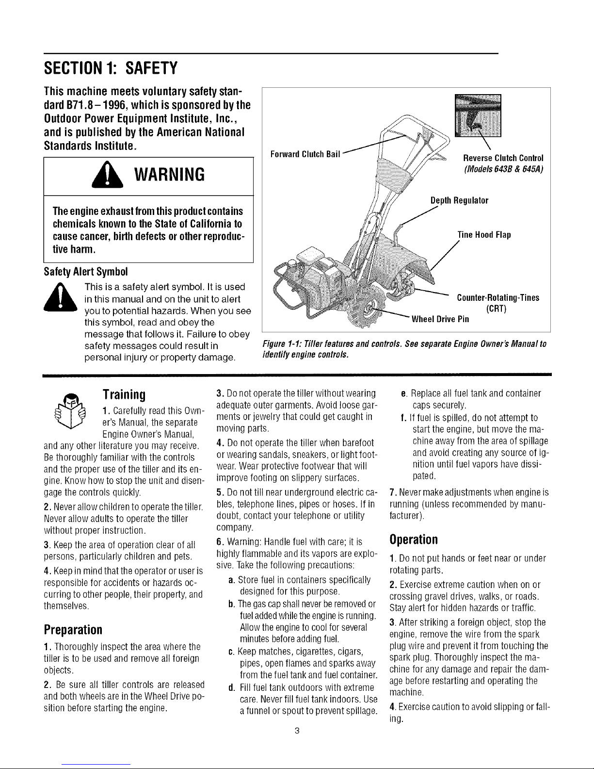
ForwardClutchBail
ReverseClutchControl
(Mode/s643B&645A)
DepthRegulator
TineHoodFlap
,_ This is a safety alert symbol. It is used
and any other literature you mayreceive.
Bethoroughly familiar with the controls
andthe proper useof the tiller and its en-
gine. Knowhowto stop the unit and disen-
gagethe controls quickly.
2. Neverallow childrento operatethetiller.
Neverallow adults to operatethe tiller
without proper instruction.
3. Keepthe area of operationclear of all
persons, particularly children and pets.
4. Keepin mindthat the operatoror user is
responsible for accidentsor hazardsoc-
curring to otherpeople,their property,and
themselves.
in this manual and on the unit to alert
you to potential hazards. When you see
this symbol, read and obey the
message that follows it. Failure to obey
safety messages could result in
personal injury or property damage.
3. Donot operatethetiller without wearing
1. Carefully readthis Own-
Training
er's Manual,the separate
Engine Owner'sManual,
adequateouter garments. Avoid loose gar-
ments or jewelry that could get caught in
moving parts.
4. Donot operatethe tiller when barefoot
or wearing sandals, sneakers,or light foot-
wear.Wearprotective footwear that will
improve footing on slippery surfaces.
5. Donottill nearunderground electricca-
bles, telephone lines, pipes or hoses.If in
doubt, contactyour telephoneor utility
company.
6. Warning: Handlefuel with care; it is
highly flammableand its vaporsareexplo-
sive.Takethe following precautions:
a. Storefuel in containers specifically
b. Thegascapshall neverberemovedor
Preparation
1. Thoroughly inspect the areawherethe
tiller is to be usedand removeall foreign
objects.
2. Be sure all tiller controls are released
and both wheelsare inthe Wheel Drive po-
sition beforestarting the engine.
c. Keepmatches,cigarettes, cigars,
d. Fillfuel tank outdoors with extreme
Counter-Rotating-Tines
(CRT)
Drive Pin
Figure 1-1: Tiller featuresand contre/s.See separateEngineOwner'sManua/ to
identifyenginecontre/s.
e. Replaceall fueltank andcontainer
caps securely.
f. Iffuel isspilled, do not attempt to
start the engine,but move the ma-
chineawayfrom the areaof spillage
and avoid creating any source of ig-
nition until fuel vapors havedissi-
pated.
7. Nevermakeadjustments when engineis
running (unless recommendedby manu-
facturer).
Operation
1. Do not put hands or feetnear or under
rotating parts.
designedfor this purpose.
fueladdedwhiletheengineisrunning.
Allowthe engineto coolforseveral
minutesbeforeaddingfuel.
pipes, openflamesandsparks away
from thefuel tank and fuelcontainer.
care.Neverfill fueltank indoors. Use
a funnel or spout to preventspillage.
2. Exerciseextremecaution when on or
crossing gravel drives, walks, or roads.
Stay alert for hidden hazardsor traffic.
3. After striking a foreign object, stop the
engine, removethe wire from the spark
plug wire andprevent it from touching the
spark plug. Thoroughly inspect the ma-
chine for any damageand repairthe dam-
agebefore restarting and operatingthe
machine.
4.Exercisecautionto avoidslipping orfall-
ing.
Page 4
5.Iftheunitshouldstarttovibrateabnor-
mally,stoptheengine,disconnectthe
sparkplugwireandpreventitfromtouch-
ingthesparkplug,andcheckimmediately
forthecause.Vibrationisgenerallya
warningoftrouble.
6.Stoptheengine,disconnectthespark
plugwireandpreventitfromtouchingthe
sparkplug,wheneveryouleavetheoperat-
ingposition,beforeuncloggingthetines,
orwhenmakinganyrepairs,adjustments
orinspections.
7.Takeallpossibleprecautionswhenleav-
ingthemachineunattended.Stoptheen-
gine.Disconnectthesparkplugwireand
moveitawayfromthesparkplug.Besure
thatbothwheelsareintheWheelDrivepo-
sition.
8.Beforecleaning,repairing,orinspect-
ing,stoptheengineandmakecertainall
movingpartshavestopped.Disconnect
thesparkplugwireandpreventitfrom
touchingthesparkplugtopreventacci-
dentalstarting.
9.Theflaponthetinehoodmustbedown
whenoperatingthetiller.
10.Neverusethetillerunlessproper
guards,plates,orothersafetyprotective
devicesareinplace.
11.Donotruntheengineinanenclosed
area.Engineexhaustcontainscarbon
monoxidegas,adeadlypoisonthatis
odorless,colorless,andtasteless.
12.Keepchildrenandpetsaway.
13. Neveroperatethe tiller underengine
powerif thewheels arein theFreewheel
position.Inthe Freewheelposition, the
wheelswill not hold the tiller back andthe
revolvingtines could propel thetiller rapid-
ly,possibly causingloss of control. Always
engagethe wheels with the wheel drive
pins in theWheel Drive position before
starting the engine or engaging the
tines_vheelswith the Forward Clutch Bail
(all models)or the ReverseClutchcontrol
(Models 643B& 645A only).
14. Be aware that the tiller may unex-
pectedlybounceupwardorjumpforward
if thetines shouldstrikeextremelyhard
packedsoil, frozenground,or buriedob-
stacleslike largestones, roots,or
stumps.
If indoubtaboutthe tilling conditions,al-
ways usethe following operating precau-
tionsto assistyouin maintainingcontrol
of thetiller:
a. Walk behindandto one side of the
tiller, usingone handon thehandle
barsRelax yourarm, but usea
securehandgrip.
b. Useshallowerdepthregulator
settings,working graduallydeeper
with each pass.
c. Useslowerenginespeeds.
d. Clearthetilling area of all large
stones,rootsor other debris.
e. Avoidusingdownwardpressureon
thehandlebars.If needbe, use
slight upwardpressureto keep the
tinesfrom diggingtoodeeply.
f. Beforecontacting hard packedsoil
at the endof a row,reduceengine
speedand lift the handlebarsto
raise the tines out of the soil.
g. In an emergency, stopthetinesand
wheels byreleasing whichever
clutch controlis engaged.Do not
attemptto restrainthetiller.
15. Donot overloadthe tiller's capacityby
attempting to till too deeply at too fast a
rate.
16. Neveroperate the tiller at high trans-
port speeds onhard or slippery surfaces.
Look behind and usecarewhen backing
up.
17. Donot operatethetiller on aslope that
is too steep for safety.When on slopes,
slow down and makesure you have good
footing. Neverpermit thetiller to freewheel
down slopes.
18. Neverallow bystandersnearthe unit.
19. Onlyuseattachmentsand accessories
that areapproved by the manufacturer of
the tiller.
20. Usetiller attachmentsand accessories
when recommended.
21. Neveroperatethe tiller without good
visibility orlight.
22. Neveroperatethe tiller if you aretired;
or underthe influence ofalcohol, drugs or
medication.
23. Operatorsshall not tamper with theen-
gine-governor settings onthe machine;
the governor controls the maximum safe
operatingspeedto protect the engineand
all movingparts from damagecaused by
overspeed.Authorized serviceshall be
sought if a problem exists.
24. Do not touch engine parts which may
behot from operation.Let parts cool down
sufficiently.
25. Pleaseremember:Youcan alwaysstop
the tines and wheels by releasingthe For-
ward Clutch Bailor on Models 643B &
645Athe ReverseClutchcontrol, (which-
evercontrol isengaged),or bymoving the
ignition switch and/orthrottle control lever
on the engineto "OFF" or "STOP".
26. Toload or unloadthe tiller, seethe in-
structions in Section4 of this Manual.
27. Useextreme caution when reversing
or pullingthe machinetowards you.
28. Startthe enginecarefully accordingto
instructions and with feetwell away from
the tines.
29. Neverpick up or carry a machinewhile
the engineis running.
MaintenanceandStorage
1. Keepthe tiller, attachmentsand acces-
sories in safeworking condition.
2. Checkall nuts, bolts, and screws for
proper tightness to besurethe equipment
is in safeworking condition.
3. Neverstore thetiller with fuel in thefuel
tank inside abuilding whereignition sourc-
esare presentsuchashot waterandspace
heaters,furnaces, clothes dryers, stoves,
electric motors, etc.). Allow the engine to
cool beforestoring the unit in any enclo-
sure.
4. Toreducethe chancesof a fire hazard,
keepthe enginefreeofgrass, leaves,or ex-
cessivegrease.
5. Storegasolinein acool, well-ventilated
area,safelyawayfrom anyspark- or
flame-producing equipment. Store gaso-
line in an approvedcontainer,safelyaway
from the reachof children.
6. Referto the Maintenancesections of
this Manualand the separateEngineOwn-
er'sManualfor instructions ifthe unitis to
bestored for an extendedperiod.
7. Neverperform maintenancewhilethe
engineis running orthe sparkplug wire is
connected,exceptwhen specifically in-
structed to do so.
8. Ifthe fueltank hasto be drained,dothis
outdoors.
Page 5
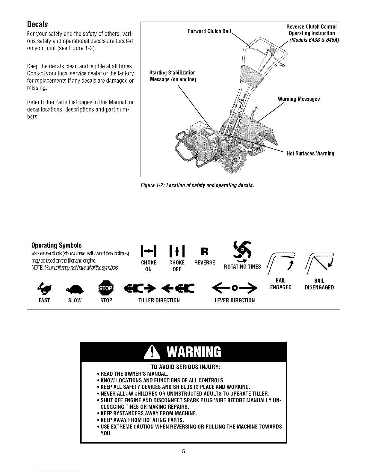
Decals
Foryour safety and the safetyof others, vari-
ous safety andoperational decalsare located
on your unit (seeFigure 1-2).
ForwardClutch Bail
ReverseClutch Control
OperatingInstruction
Keepthe decalsclean and legible atall times.
Contactyour localservicedealeror thefactory
for replacementsif any decalsaredamagedor
missing.
Referto the Parts List pagesin this Manualfor
decallocations, descriptionsand part num-
bers.
_ (Models 643B& 645A
StartingStabilization
Message(on engine)
WarningMessages
Hot Surfaces Warning
Figure1-2: Locationof safety and operatingdeca/s.
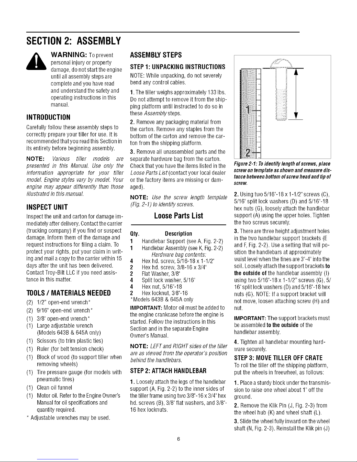
OperatingSymbols
Varioussymbols(shownhere,_dthworddescrip'dons)
maybeusedonte'dllerandengine.
NOTE:YourunihT_ynothaveallof_esymbols.
FAST SLOW STOP
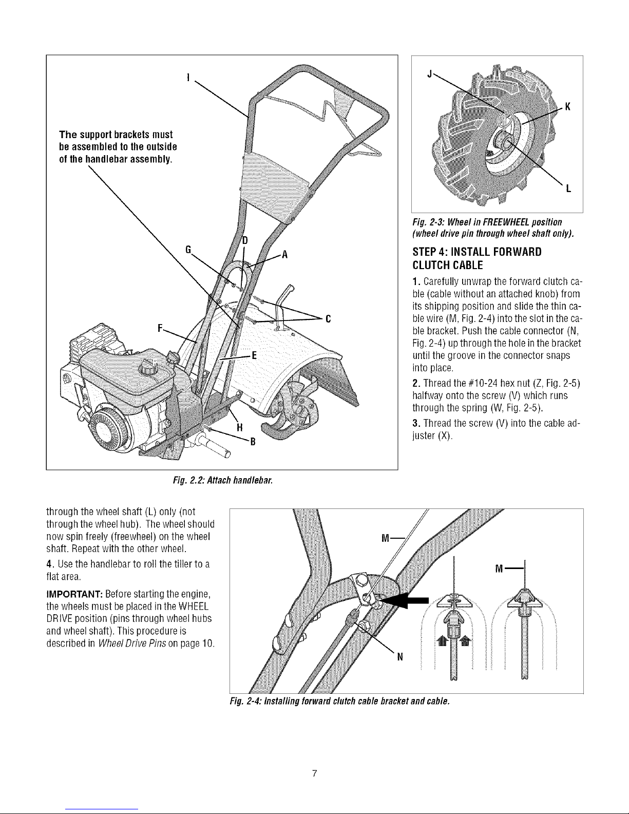
* READTHEOWNER'SMANUAL.
* KNOWLOCATIONSANDFUNCTIONSOFALLCONTROLS.
* KEEPALLSAFETYDEVICESANDSHIELDSIN PLACEAND WORKING.
. NEVERALLOWCHILDRENORUNINSTRUCTEDADULTSTOOPERATETILLER.
° SHUTOFFENGINEANDDISCONNECTSPARKPLUGWIRE BEFOREMANUALLYUN-
CLOGGINGTINESORMAKINGREPAIRS.
° KEEPBYSTANDERSAWAYFROMMACHINE.
° KEEPAWAYFROM ROTATINGPARTS.
° USEEXTREMECAUTIONWHENREVERSINGOR PULLINGTHE MACHINETOWARDS
YOU.
I"1 I*1 R
CHOKE CHOKE REVERSE
ON OFF ROTATINGTINES
<--o-->
TILLERDIRECTION
TO AVOID SERIOUS INJURY:
LEVERDIRECTION
BAIL
ENGAGED
BAIL
DISENGAGED
Page 6
SECTION2: ASSEMBLY
WARNING: Toprevent
personalinjury or property
damage,do notstart the engine
until all assemblysteps are
completeandyou have read
and understandthesafety and
operating instructions in this
manual.
INTRODUCTION
Carefullyfollow theseassemblysteps to
correctly prepareyour tiller for use. It is
recommendedthatyou readthis Sectionin
its entirety beforebeginning assembly.
NOTE: Various tiller models are
presented in this Manual. Use only the
information appropriate for your tiller
model. Enginestyles vary by model, Your
engine may appear differently than those
illustrated in this manual.
INSPECTUNIT
Inspect the unitand carton for damageim-
mediatelyafter delivery.Contactthe carrier
(trucking company) if you find or suspect
damage.Inform them of the damageand
request instructions for filing a claim. To
protect your rights, put your claim in writ-
ing and maila copyto the carrierwithin 15
days after the unit has beendelivered.
ContactTroy-Bilt LLCif you needassis-
tance inthis matter.
TOOLS/ MATERIALSNEEDED
(2) 1/2" open-end wrench*
(2) 9/16" open-endwrench*
(1) 3/8" open-endwrench*
(1) Largeadjustable wrench
(Models 643B & 645A only)
(1) Scissors (totrim plasticties)
(1) Ruler (for belttension check)
(1) Block of wood (to support tiller when
removing wheels)
(1) Tirepressure gauge(for models with
pneumatictires)
(1) Cleanoil funnel
(1) Motor oil. Refertothe EngineOwner's
Manualfor oilspecificationsand
quantityrequired.
* Adjustable wrenchesmay be used.
ASSEMBLYSTEPS
STEP 1: UNPACKING INSTRUCTIONS
NOTE:While unpacking, do not severely
bend any control cables.
1.Thetiller weighs approximately 133 Ibs.
Do notattempt to remove it from the ship-
ping platform until instructed to do so in
these Assembly steps.
2. Removeany packagingmaterial from
the carton. Removeany staples from the
bottom of the cartonand removethe car-
ton from the shipping platform.
3. Removeall unassembledparts andthe
separatehardwarebag from the carton.
Checkthat you havethe items listed in the
LooseParts List (contactyour localdealer
or the factory itemsare missing or dam-
aged).
NOTE: Use the screw length template
(Fig,2-1) to identify screws,
LooseParts List
Qty. Description
1 HandlebarSupport (seeA, Fig. 2-2)
1 HandlebarAssembly(seeK,Fig.2-2)
Hardwarebag contents:
4 Hexhd. screw, 5/16-18 x 1-1/2"
2 Hexhd. screw, 3/8-16 x 3/4"
2 FlatWasher,3/8"
4 Split lock washer,5/16"
4 Hex nut, 5/16"-18
2 HexIocknut,3_8"-16
*Models 643B & 645Aonly
IMPORTANT:Motor oil must beaddedto
the enginecrankcasebeforetheengine is
started. Followthe instructions inthis
Sectionand in the separateEngine
Owner's Manual.
NOTE: LEFTandRIGHTsides of thetiller
are as viewedfrom theoperator's position
behind the handlebars.
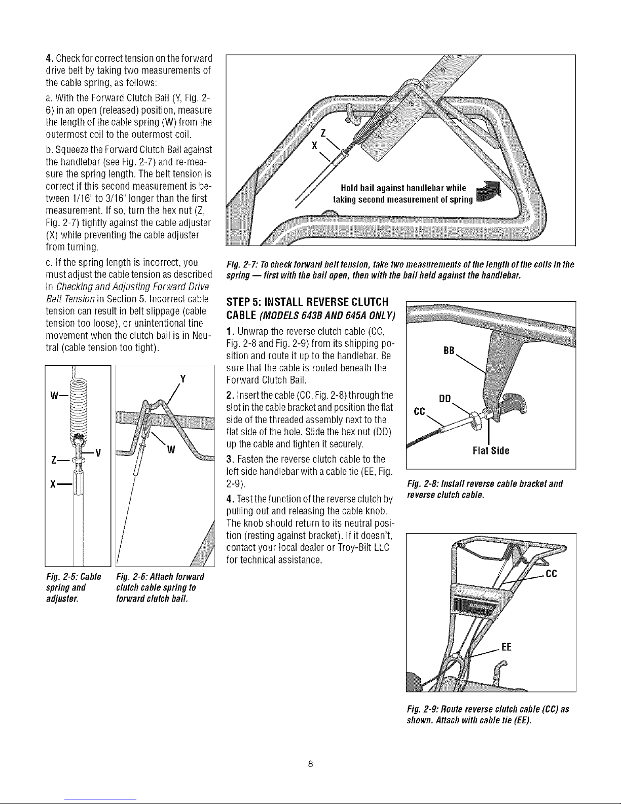
STEP 2: ATTACHHANDLEBAR
1. Looselyattachthe legs of thehandlebar
support (A, Fig. 2-2) to the innersides of
the tiller frame usingtwo 3/8"-16x3/4" hex
hd.screws (B),3/8" flat washers, and3/8"-
16 hexIocknuts.
_iiii
Figure2-1: Toidentifylengthofscrews,place
screwontemplateasshownandmeasuredis-
tancebetweenbottomofscrewheadandtipof
screw.
2. Usingtwo 5/16"-18x 1-1/2"screws (C),
5/16"split lock washers (D) and 5/16"-18
hexnuts (G), loosely attach the handlebar
support (A)usingthe upperholes.Tighten
thetwo screws securely.
3. Therearethree height adjustment holes
in the two handlebar support brackets (E
and F,Fig. 2-2). Usea setting that will po-
sition the handlebarsat approximately
waist levelwhenthetines are3"-4"intothe
soil. Looselyattachthe support bracketsto
theoutsideof the handlebarassembly (I)
usingtwo 5/16"-18x 1-1/2" screws (G), 5/
16"split lockwashers(D)and5/16"-18 hex
nuts (G). NOTE:If asupport bracketwill
not move, loosenattaching screw (H) and
nut.
IMPORTANT:The support bracketsmust
beassembledto theoutside ofthe
handlebarassembly.
4. Tightenall handlebarmounting hard-
waresecurely.
STEP 3: MOVE TILLER OFF CRATE
Toroll the tiller off the shipping platform,
put the wheels in freewheel, asfollows:
1. Placeasturdy block underthetransmis-
sion to raise one wheelabout 1" off the
ground.
2. Removethe Klik Pin (J, Fig. 2-3) from
the wheelhub (K) and wheelshaft (L).
3. Slidethe wheelfully inwardonthewheel
shaft (N,Fig. 2-3). Reinstallthe Klikpin (J)
Page 7
The supportbracketsmust
be assembledto theoutside
of the handlebarassembly.
Fig.2-3: WheelinFREEWHEELposition
(wheeldrivepin throughwheelshaftonly).
STEP 4: INSTALL FORWARD
CLUTCH CABLE
1. Carefullyunwrapthe forward clutch ca-
ble(cablewithout an attachedknob) from
its shipping position andslide the thin ca-
blewire (M, Fig.2-4) intothe slot in the ca-
blebracket. Pushthe cableconnector (N,
Fig.2-4) upthrough the holein thebracket
untilthe groove in the connector snaps
into place.
2. Threadthe#10-24 hexnut (Z, Fig. 2-5)
halfway ontothe screw (V)which runs
through the spring (W,Fig. 2-5).
3. Threadthe screw (V) into the cablead-
juster (X).
Fig. 2.2: Attachhandlebar.
through the wheel shaft (L) only (not
through thewheelhub). Thewheelshould
now spin freely (freewheel)on the wheel
shaft. Repeatwith the other wheel.
4. Usethe handlebarto roll the tiller to a
flat area.
IMPORTANT:Beforestarting the engine,
the wheels must beplacedin theWHEEL
DRIVEposition (pinsthrough wheelhubs
andwheelshaft). This procedureis
described in WheelDrivePins on page 10.
Fig. 2-4:/nstal/ing forward clutchcable bracketand cable.
Page 8
4. Checkfor correcttension ontheforward
drive belt bytaking two measurementsof
the cablespring, as follows:
a.With the Forward Clutch Bail (Y,Fig. 2-
6) in an open (released)position, measure
the length ofthe cable spring (W) from the
outermost coil to the outermost coil.
b. Squeezethe ForwardClutch Bailagainst
the handlebar(see Fig. 2-7) and re-mea-
surethe spring length. Thebelt tension is
correct if this second measurementis be-
tween 1/16"to 3/16" longer thanthe first
measurement.If so,turn the hexnut (Z,
Fig. 2-7) tightly against the cable adjuster
(X) while preventing the cable adjuster
from turning.
c. Ifthe spring length is incorrect, you
must adjustthe cabletension asdescribed
in Checkingand Adjusting ForwardDrive
Belt Tensionin Section5. Incorrect cable
tension can result inbelt slippage (cable
tension too loose), or unintentional tine
movement when the clutch bail is in Neu-
tral (cabletension too tight).
Wm
W
: v
iiiiiiiiiiiiiiii
Fig. 2-7: Tocheckforwardbelt tension, take twomeasurementsof thelengthofthe coilsin the
spring-- first withthebah open, then withthe bah held against thehandlebar.
STEP 5: INSTALL REVERSECLUTCH
CABLE(MODELS643BAND 645A ONLY)
1. Unwrapthe reverseclutch cable (CC,
Fig.2-8 and Fig.2-9) from itsshipping po-
sition androute it up to the handlebar.Be
surethat the cableis routed beneaththe
Forward Clutch Bail.
2. Insertthecable(CC,Fig.2-8)through the
slot inthecablebracketandpositiontheflat
sideof thethreadedassemblynextto the
flat side of the hole.Slidethe hexnut (DD)
up the cable andtighten it securely.
3. Fastenthe reverseclutch cable to the
left side handlebarwith acabletie (EE,Fig.
2-9).
4. Testthefunction ofthe reverseclutch by
pulling out and releasingthe cable knob.
Theknob should return to its neutral posi-
tion (resting against bracket). If it doesn't,
contact your local dealeror Troy-Bilt LLC
for technical assistance.
Fig. 2-8: Install reverse cable bracketand
reverseclutchcable.
Flat Side
Fig.2-5: Cable
springand
adjuster.
Fig. 2-6: Attachforward
clutchcable spring to
forwardclutch bail
Fig. 2-9: Routereverse clutchcable (CC)as
shown.Attachwithcable tie (EE).
Page 9
5! =-P6:CHECKTRAHSMiSSiOH
OILLEVEL
Thetransmission wasfilledwith gearoil at
thefactory. However,you shouldcheckthe
gear oil levelatthis time to makecertain it
is correct.
IMPORTANT:Donot operatethe tiller ifthe
gear oil level is low. Doingso will result in
severedamageto the transmission com-
ponents.
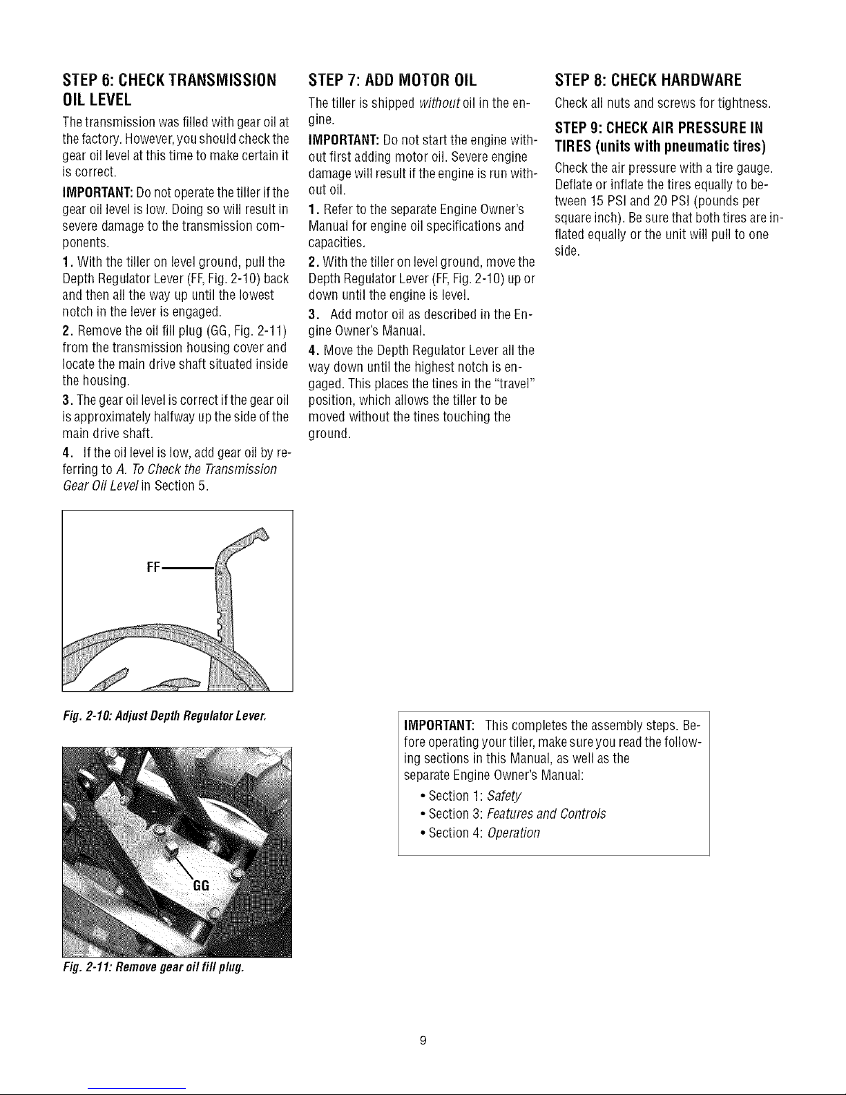
1. With the tiller on levelground, pull the
Depth RegulatorLever(FF,Fig. 2-10) back
andthen all theway up until the lowest
notch inthe lever isengaged.
2. Removethe oil fill plug (GG,Fig. 2-11)
from the transmission housing cover and
locatethe main drive shaft situated inside
the housing.
3. Thegear oil leveliscorrect if the gearoil
isapproximately halfway upthe sideofthe
main driveshaft.
4. Ifthe oil levelislow, addgear oil by re-
ferring to A, ToCheckthe Transmission
GearOil Level in Section5.
I El."/: AUU IVlUI UH UIL
Thetiller isshipped withoutoil in the en-
gine.
IMPORTANT:Donot start the engine with-
out first adding motor oil. Severeengine
damagewill resultif the engineis run with-
out oil.
1. Referto the separateEngineOwner's
Manualfor engine oil specifications and
capacities.
2. With thetiller on levelground, movethe
Depth RegulatorLever(FF,Fig.2-10) up or
down until the engine is level.
3. Addmotor oil as describedin the En-
gine Owner's Manual.
4. Movethe DepthRegulator Leverall the
way down untilthe highest notch is en-
gaged.This placesthe tines in the"travel"
position, which allows the tiller to be
moved without thetines touching the
ground.
_ I L:I."8: L;Ht:L;KHAHUWAHt:
Checkall nuts and screws for tightness.
STEP 9: CHECKAIR PRESSURE IN
TIRES (units with pneumatic tires)
Checkthe air pressurewith atire gauge.
Deflateor inflatethe tires equally to be-
tween 15 PSiand 20 PSi (pounds per
squareinch). Besurethat both tires arein-
flated equally orthe unit will pull to one
side.
Fig. 2-10: AdjustDepth Regu/atorLever.
Fig. 2-11: Removegear oil fill plug.
IMPORTANT: This completesthe assembly steps. Be-
fore operatingyour tiller, makesureyou readthefollow-
ing sectionsin this Manual,as well as the
separateEngineOwner'sManual:
• Section 1: Safety
• Section 3: Featuresand Controls
• Section 4: Operation
Page 10
SECTION3: FEATURESANDCONTROLS
_ ARNING: Before
INTRODUCTION
This Section describesthe location and
function ofthecontrols onyourtiller. Refer
to the following Section, Operationfor de-
tailed operatinginstructions.
Practice usingthese controls, with the en-
gine shut off, untilyou understandthe op-
eration ofthe controls andfeelconfident
with eachof them.
ENGINE CONTROLS
Referto the enginemanufacturer'sEngine
Owner'sManual (included in the tiller liter-
aturepackage)to identify the controls on
your engine.
IMPORTANT:Thecontrol for stopping the
engine is locatedonthe engine.
WHEEL DRIVE PINS
Eachwheel is equippedwith a wheel drive
Klik pin (A, Figures3-2 and 3-3) that se-
curesthe wheelto the wheel shaft (B).The
wheelscan be positioned in either a
WHEELDRIVEor a FREEWHEELmode.
_ WARNING: Neverallow
Beforestarting the engine,put both wheels
in the WHEELDRIVEposition byinserting
the wheeldriveKlikpinsthrough the wheel
hubsandthewheelshaft. Doingso "locks"
the wheels to the wheelshaft, causing the
wheelsto turn when eitherthe
operatingyour machine,
carefully readand understand
all safety, controls and
operating instructions in this
Manual,the separateEngine
Owner's Manual,and on the
decalson the machine.
Failureto follow these
instructions can result in
serious personal injury.
either ofthewheelsto bein the
FREEWHEELposition whenthe
engineis running. Alwaysput
both wheelsin the WHEEL
DRIVEposition beforestarting
the engine.
Failureto comply could cause
loss of tiller control, property
damage,or personalinjury.
ForwardClutch
Wheel Drive Pin
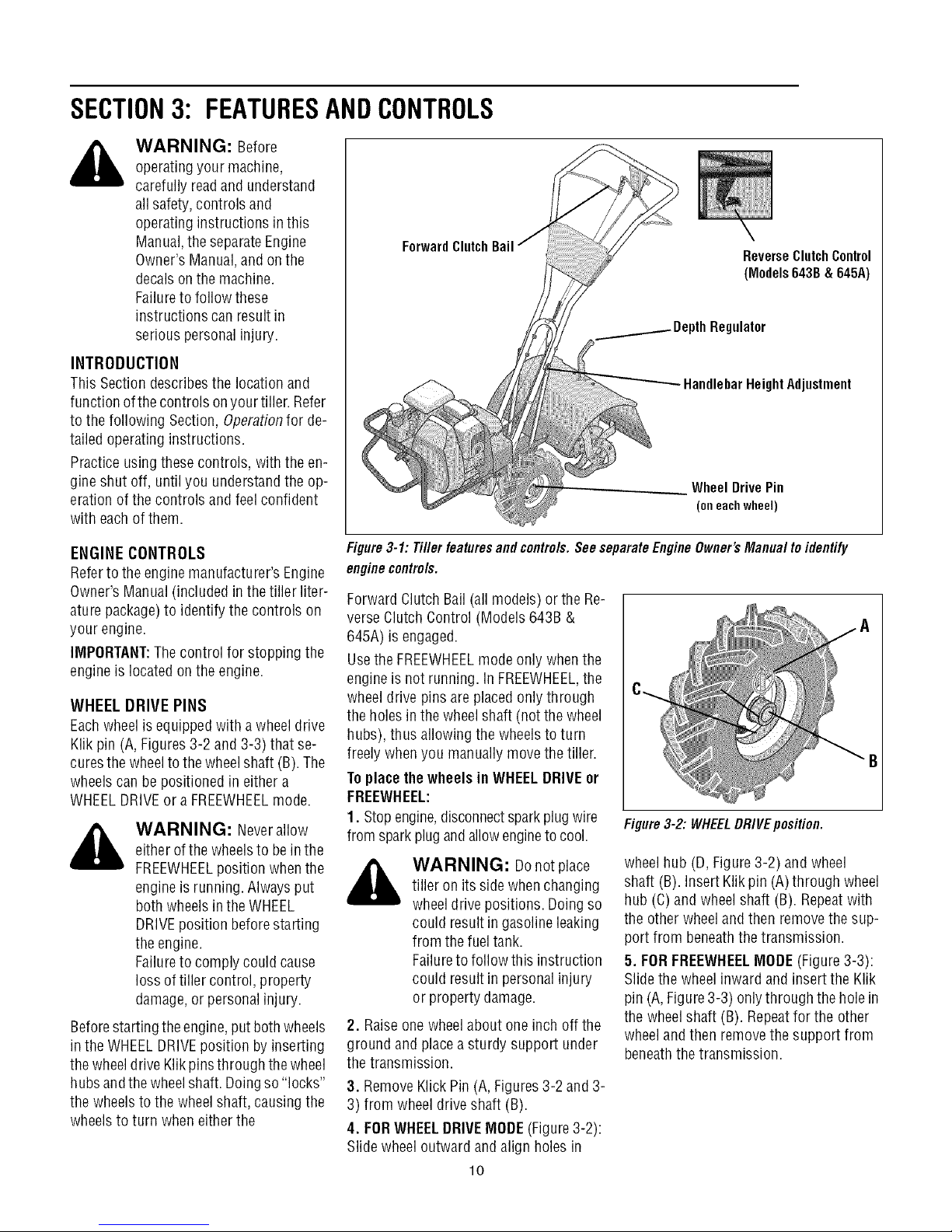
Figure3-1: Tiller features and controls.See separateEngine Owner's Manual toidentify
enginecontrols.
Forward Clutch Bail (all models) or the Re-
verse Clutch Control (Models 643B &
645A) is engaged.
Usethe FREEWHEELmode only whenthe
engineis not running. InFREEWHEEL,the
wheeldrive pinsare placedonly through
the holes in thewheelshaft (not the wheel
hubs), thus allowing the wheelsto turn
freely when you manually movethe tiller.
Toplacethe wheels in WHEELDRIVEor
FREEWHEEL:
1. Stopengine,disconnectsparkplug wire
from sparkplug andallowengineto cool.
_ WARNING: Donotplace
2. Raiseone wheelabout one inch off the
ground andplaceasturdy support under
the transmission.
3. RemoveKlick Pin (A, Figures3-2 and 3-
3) from wheel driveshaft (B).
4. FORWHEELDRIVEMODE(Figure3-2):
Slide wheel outward andalign holes in
tiller on its sidewhen changing
wheeldrivepositions. Doingso
could result ingasoline leaking
from the fuel tank.
Failureto follow this instruction
could result in personal injury
or propertydamage.
lO
Figure3-2: WHEELDRIVEposition.
wheelhub (D,Figure 3-2) and wheel
shaft (B). Insert Klik pin(A) through wheel
hub (C)and wheelshaft (B). Repeatwith
the other wheelandthen removethe sup-
port from beneaththe transmission.
5. FORFREEWHEELMODE(Figure 3-3):
Slide the wheelinward and insert the Klik
pin (A,Figure3-3) onlythrough thehole in
the wheelshaft (B). Repeatfor the other
wheeland then removethe support from
beneaththe transmission.
ReverseClutchControl
(Models643B&645A)
Regulator
HeightAdjustment
(oneachwheel)
"B
Page 11

Figure3-3: FREEWHEELposition.
WARNING: Beforestarting
engine,besurethat both
wheelsare in WHEELDRIVE
position. SeeWheelsDrivePins
for instructions.
Engagingthe Forward Clutch
Bail or ReverseClutchControl
(if equipped) whenthewheels
arenot in WHEELDRIVEcould
allowthe tinesto rapidly propel
the tiller forward or backward.
Failureto comply could cause
loss of tiller control, property
damage,or personalinjury.
FORWARDCLUTCHBAIL
TheForward Clutch Bail(D, Figure3-4)
controls the engagementof forward drive
to the wheelsand tines.
Tooperatethe ForwardClutchBail:
1. Put wheelsin WHEELDRIVEposition
(see"WARNING"statement above).
2. Lift and holdthe clutch bail (D,Figure 3-
4) againstthe handlebarto startthewheels
andtines rotating in a forward direction.
3. Releasethe clutch bail to disengage
(stop) the wheels andtines (theenginewill
continue to run).
REVERSECLUTCHCONTROL
(Models 643B & 645A only)
TheReverseClutchControl (E,Figure3-4)
controls the engagementof reversedrive
to the wheelsandtines.The reversingfea-
ture is used for maneuvering the tiller
only-- never engage the tines in the
ground while operatingin reverse.
WARNING: Useextreme
caution when reversing or
pulling the machinetowards
you. Look behindto avoid
obstacles.
Neverattemptto till in reverse.
Failureto follow this warning
could result in personal injury
or propertydamage.
Tooperatethe ReverseClutchControl:
1. Putwheels in WHEELDRIVEposition
(see"WARNING"statement at the left).
2. Stopall tiller motion by releasingthe
Forward Clutch Bail.
3. Lift the handlebar untilthe tines clear
the ground, look behindyou to avoid any
obstacles,and then pull the control knob
(E, Figure3-4) out.The wheels andtines
will rotate in a reversedirection.
4. Releasethe control knobto disengage
(stop) the wheels andtines (theenginewill
continue to run).
Figure3-4:Allmodelshavea ForwardClutch
Bail(E). OnlyModel634,4haveaReverse
ClutchCentre/(F).
DEPTHREGULATORLEVER
Thislever(F,Figure3-5) controls thetilling
depth of thetines. Pullthe lever backand
slide it up or downto engagethe notched
height settings.
The"travel position" (highestnotch) raises
the tines approximately1-1/2"off the
ground, allowingthe tiller to bemoved
without the tines contacting the ground.
This setting should also be usedwhen
starting the engine.
Moving the lever upwardwill increasethe
tilling depth.The lowest notch allows a till-
ing depthof approximately6", depending
on soil conditions.For best results,always
begintilling atavery shallow depthsetting
and gradually increasethe tilling depth.
to till too deeplytoo quickly.
WARNING: Donotattempt
Graduallywork downto deeper
tilling depths.
Placethe DepthRegulator
Leverin the "travel" position
beforestarting theengine.This
position prevents thetines from
touching the ground untilyou
are readyto begintilling.
Failureto follow this warning
could result in personalinjury
or propertydamage.
TravelPosition
Figure3-5: DepthRegulatorLever (G).
HANDLEBARHEIGHT ADJUSTMENT
Thehandlebarheight isadjustableto three
different settings (Figure3-6). In general,
adjust the handlebarsso they areat waist
levelwhenthe tines are3"-4" in the soil.
Toadjust the handlebars:
1. Stopengine,disconnectspark plugwire
from sparkplug and allow engineto cool.
2. Removehardware,reposition handle-
bars,and reinstall hardwaresecurely.
High
Medium
Figure3-6: Handlebarheightadjustment.
11
Page 12

SECTION4: OPERATION
_ ARNING: Before
operatingyour machine,
carefully readand understand
all safety (Section 1),controls
(Section 3) and operating
instructions (Section4) inthis
Manual,the separateEngine
Owner's Manual,and on the
decalson the machine.
Failureto follow these
instructions can result in
serious personal injury.
INTRODUCTION
Readthis OperationSection andthe sepa-
rate EngineOwner'sManualbeforeyou
start the engine.Then,take the time to fa-
miliarize yourself with the basic operation
of thetiller before usingit in the garden.
Findan open,levelareaand practice using
the tiller controls without thetines engag-
ing the soil (put tines in "travel" setting).
Onlyafter you've becomecompletely fa-
miliar with thetiller shouldyou beginusing
it in the garden.
BREAK-INOPERATION
Perform the following maintenanceafter
the first two (2) hours of new operation
(see MaintenanceSection in this manual
and in the Engine Owner'sManual).
1. Changeengineoil.
2. Checkfor looseor missinghardwareon
unit. Tightenor replaceas needed.
3. Checktension onforward drive belt.
4. Checktransmission gear oil level.
STARTINGANDSTOPPING
Pre-StartChecklist
With the spark plug wire disconnected
from the sparkplug, perform the following
checksand services beforeeach use:
1. Readthe Safetyand Controls Sections
in this manual. Readthe separateEngine
Owner's Manualprovidedwith the unit.
2. Putthe wheels inthe WHEELDRIVEpo-
sition (wheel pins must be through holes
in wheelhubs andwheel shaft).
3. Checkunit for loose or missing hard-
ware. Serviceas required.
4. Checkengineoil level.SeeEngineOwn-
er's Manual.
ReverseClutchControl
(Mode/s643B&
ClutchBail
Fig. 4-1
5. Checkthat all safety guards andcovers
are in place.
6. Checkair cleanerand engine cooling
system. SeeEngineOwner's Manual.
_ WARNING: GASOLINEIS
7. Fillthefueltank with gasoline according
to the directions inthe separate Engine
Owner's Manual.Follow all instructions
and safety rules carefully.
8. Attachspark plug wire to spark plug.
Startingthe Engine
Thefollowing steps describe how to start
and stop the engine.
_ WARNING: Donotattempt
HIGHLYFLAMMABLEAND ITS
VAPORSAREEXPLOSIVE.
Followgasolinesafety rules in
this Manual(seeSection 1)and
in the separateEngineOwner's
Manual.
Failureto follow gasoline safety
instructions can result in
serious personal injury and
property damage.
to engagethetines or wheels
until you havereadall ofthe
operatinginstructions in this
Section.Also, reviewthe safety
rules in Section1: Safety,and
the tiller and enginecontrols
information in Section3:
Featuresand Controls.
DepthRegulator
DrivePin
1. Completethe Pre-StartCheckliston this
page.
2. Putthe wheels inthe WHEELDRIVEpo-
sition (seeWheelDrivePinsin Section3 of
this manual).
,_ WARNING: Tohelp
• Before starting engine, put both
wheels in the WHEELDRIVEposition.
Never have wheels in FREEWHEELpo-
sition when engine is running.When
thewheels are in FREEWHEEL,theydo
not hold back the tiller and the tines
couldpropelthe tiller rapidly
forwardor backward.
• Before starting engine, put Forward
Clutch Bail (all models) and Reverse
Clutch Control (Models 643B & 645A
only)in neutral (disengaged)positions
by releasinglevers.
• Never run engine indoors or in en-
closed,poorlyventilatedareas. Engine
exhaustcontainscarbonmonoxide,an
odorlessanddeadlygas.
• Avoidenginemufflerandnearbyareas.
Temperaturesin these areas may ex-
ceed 150° F.
3. Movethe Depth RegulatorLeverall the
way down to the "travel" position, sothat
thetines clearthe ground.
4. Releaseall controls on the tiller.
5. Onengine's with afuel shut-off valve,
turn valve to openposition, as instructed
in the separateEngine Owner'sManual.
6. Put ignition switch and/or throttle con-
trol leverlocated on engine in the "ON",
"RUN", "FAST"or "START"position, asin-
structed inthe EngineOwner's Manual.
7. Chokeor prime engine,as instructed in
EngineOwner's Manual.
8. Put one hand onfuel tank to stabilize
unitwhenpulling starter ropehandle.Then
userecoilstarter to start engine,as in-
structed inthe EngineOwner's Manual.
Whenenginestarts, graduallymove choke
lever (if so equipped) to "NO CHOKE",
"CHOKEOFF"or "RUN" position.
9. Usethe "FAST"throttle speedsetting
whentilling.
preventserious personalinjury
or damageto equipment:
12
Page 13

Stopping the Engineand Tiller
1. Tostop the wheelsandtines, releasethe
Forward Clutch Bail (all models) orthe Re-
verse Clutch Control (Models 643B &
645A) -- whichevercontrol is in use.
2. Tostop the engine,put the ignition
switch and/or thethrottle control leverin
the "OFF"or "STOP"position.
OPERATINGTHETILLER
Thefollowing operating instructions pro-
videguidelinesto using your tiller effec-
tively and safely. Besure to read Tilling
Tips & Techniquesinthis Section before
actually putting the tines into the soil.
This is a"Counter-Rotating-Tine" (CRT)
tiller. It operatesdifferently from "Stan-
dard-Rotating-Tine" (SRT)tillers. Asthe
wheels pull forward, the tines rotate back-
ward, creating an "uppercut" action which
digs deeply, uprooting soil and weeds.
1. Followthe Pre-Start Checklistatthe be-
ginning of this Section. Besurethat the
wheelsare in the WHEELDRIVEposition.
2. Movethe DepthRegulator Leverall the
way down, so that thetines clearthe
ground. Usethis position when practicing
with thetiller and when travelingbetween
tilling sites. Beforeactuallytilling, move
the leverto the desireddepth setting (see
Tilling Tips & Techniques).
3. Start engineand allow it to warm up.
Thenput throttle in "FAST"setting.
4. Forforwardmotion of the wheelsand
powerto the tines:
(a) PullForward Clutch Bail (Fig.4-1) up
against handlebar.Releasebail to stopfor-
ward motion of wheels and tines.
(b) Whentilling, relaxand letthe wheels
pull the unit while thetines dig.Walk be-
hind anda littleto onesideof the unit. Use
one hand, yet keepa light--but secure--
grip onthe handlebar (while keepingyour
arm loose). SeeFig.4-2. Letthe unit move
at its own paceand donot pushdown on
the handlebarsto try and forcethe tines to
dig deeper-- this takes weight off the
wheelsand reducestraction.
,_ WARNING: Donotpush
down onthe handlebarsto try
to makethe tiller till more
deeply.This prevents the
wheelsfrom holding the tiller
backand canallowthe tines to
rapidly propelthe tiller forward,
which could resultin loss of
control, property damage,or
personalinjury.
5. Forreverse motion ofthe wheelsand
tines (Models643B & 645A only):
(a) Look behindand exercisecautionwhen
operating in reverse.Do not till while in
reverse.
(b) Stopall forward motion. Lift handlebar
with one handuntil tines areoff the ground
andthen pull ReverseClutchControl knob
out (seeFig.4-3). Tostop reversing,letgo
of ReverseClutch Control knob.
(b) Swing the handlebarto theleft so the
rightwheeltakes a "step" backward.Next
swing the handlebarto the rightso the left
wheel"steps" backward.Repeatas needed.
(c) If longer distances needto becovered
in reverse,shut off the engine,then place
thetwo wheels in FREEWHEEL.
7. ToTurnthe Tiller Around:
(a) Practiceturning the tiller in a level,
openarea.Beverycarefulto keepyour feet
and legs away from the tines.
(b) Tobeginaturn, lift the handlebarsuntil
thetinesareoutofthe groundandtheengine
andtinesarebalancedoverthewheels(Fig.
4-4).
(c)With tiller balanced,push sideways on
handlebarto steer in directionof turn (Fig.
4-5). After turning, slowly lower tines into
soil to resumetilling.
Fig. 4-4: Tobegin turn,lift handlebarsuntil
tinesare outof groundand unit is balanced.
Fig.4-2:Useonehandtoguidetiller when
movingforward.
Fig.4-3:Raisetinesoffgreundandlook
behindwhenmovinginreverse.
6. Tomovethe Model643Cin reversefor
short distances:
(a) Releaseforward ClutchBail.Thenlift
handlebaruntiltines are off theground.
13
Fig. 4-5: With tines out of greund,push han-
dlebarssidewaysto turn tiller.
StoppingtheTillerandEngine
1. Tostop the wheelsandtines, releasethe
Forward Clutch Bail (all models) orthe Re-
verse Clutch Control (Models 643B &
645A) -- whichevercontrol is in use.
2. Tostop the engine,put the ignition
switch and/orthe throttle control leverin
the "OFF"or "STOP"position.
Page 14

TILLINGTIPS& TECHNIQUES
Tilling Depths
WAHNING: Before
tilling, contactyour
telephoneor utilities
companyand inquire if
undergroundequipment or
lines are usedon your
property. Donottill near
buriedelectric cables,
telephonelines, pipes or
hoses.
• Whencultivating(breakingupsurfacesoil aroundplantsto destroyweeds,seeFig.4-9), ajust thetinesto digonly 1"to 2" deep.Using
shallowtilling depthshelpspreventinjury to plantswhoseroots often growclose to the surface.If needed,lift up onthe handlebars
slightlytopreventthetinesfrom diggingtoo deeply.(Cultivatingona regularbasisnot onlyeliminatesweeds,it alsoloosensandaerates
thesoil for bettermoistureabsorptionandfaster plantgrowth.)Wateringthegardenareaafewdayspriorto tillingwill maketilling easier,
aswill lettingthe newlyworkedsoil setfor a dayor two beforemakinga final, deeptilling pass.
This is a CRT(counter-rotatingtine)tiller. Asthewheelspullforward,the tinesrotateback-
ward. Thiscreatesan "uppercut" tine actionwhich digs deeply,uprootingsoil and weeds.
Don't overloadthe engine,but dig asdeeplyas possibleon eachpass.Onlaterpasses,the
wheelsmaytendto spinin thesoft dirt. Helpthemalongbylifting upslightlyonthehandlebar
(onehand,palm up,works mosteasily).
Avoidthe temptationtopushdownon thehandlebarsinan attemptto force thetiller to dig
deeper.Doingsotakesthe weightoff the poweredwheels,causingthemto lose traction.
Withoutthe wheelsto holdthetillerback,thetineswill attemptto propelthetiller backward,
towardsthe operator.(Sometimes,slightdownwardpressureonthehandlebarswill helpget
througha particularlytoughsectionofsodor unbrokenground,butin mostcasesthiswon't
benecessary.)
ChoosingCorrectWheel& TineSpeeds With experience,you will find the "just right" tilling depthandtilling speedcombination
that is bestfor yourgarden.
Setthe enginethrottle leverata speedto givetheengineadequatepowerandyetallowit tooperateattheslowestpossiblespeed...atleast
until youhaveachievedthe maximumtilling depthyou desire.Fasterenginespeedsmaybe desirablewhenmakingfinal passesthrough
theseedbedor whencultivating.Selectionofthecorrectenginespeed,in relationto the tilling depth,will ensureasufficientpowerlevelto
do the jobwithout causingtheengineto labor.
Letthe Tiller DotheWork
Whiletilling, relaxandletthe wheelspullthe
tiller along while the tines do the digging.
Walkon thesidethat is notyet finished(to
avoidmakingfootprints inthe freshly tilled
soil) and lightly,but securelygrip the han-
dlebarwith just onehand.
AvoidMakingFootprints
Wheneverpossible, walk on the untilled
sideof the unit to avoidmakingfootprints in
your freshly tilled or cultivated soil. Foot-
prints causesoil compactionthat canham-
per root penetrationand contributeto soil
erosion. They can also "plant" unwanted
weed seeds back into the freshly tilled
ground.
Preparing Seedbeds
•Whenpreparingaseedbed,go overthesamepathtwiceinthefirst row,thenover-
lapone-halfthetiller width ontherest ofthe passes(seeFig.6).Whenfinishedin
onedirection,makea secondpassat a right angle,as shownin Fig.4-7. Overlap
eachpassfor best results(invery hardground,it maytakethreeor four passesto
thoroughlypulverizethesoil.)
• If thegardensizewill not permitlengthwiseandthencrosswisetilling, then over-
lapthefirst passesbyone-halfatiller
width,followedbysuccessivepasses ....................v .................................
at one-quarterwidth(seeFig.4-8). _ _
Fig. 4-8
AvoidTillingSoggy, WetSoil
Tilling wet soil often resultsin large,hard
clumpsof soil that caninterferewith plant-
ing.If time permits,wait aday or two after
heavyrainsto allow the soil to dry before
tilling. Testsoil bysqueezingit intoa ball.If
itcompressestooeasily,it is too wetto till.
m_
Fig. 4-6 Fig. 4-7
Cultivating
With planning, you can =,,_r,_, ..,'qr_
allow enoughroom _" _ (_
betweenrows to cultivate _ _
(seeFig.4-9). Leaveroom _ _
for the hood width,
plus enough extra _ _'
roomfor future plant Fig.4-9
growth.
14
Page 15

TillingOnSlopes
TILLINGTIPS& TECHNIQUES(CON'T)
Readthe followingrecommendationsbeforetilling onslopes:
Ifyou must gardenon a moderateslope,pleasefollowtwo veryimportantguidelines:
1.Tillonlyon moderateslopes,neveronsteepgroundwherefootingisdifficult (reviewsafe-
ty rulesin Section1:Safetyofthis manual).
2. We recommendtilling up and down slopes ratherthan terracing. Tilling vertically on a
slopeallows maximumplantingareaandalso leavesroomfor cultivating.
IMPORTANT:Whentilling onslopes, besurethecorrectoil levelis maintainedintheengine
(checkeveryone-halfhour of operation).Theinclineof the slopewill causethe oil to slant
WAHNING: Do not
operatetiller onaslopetoo
steepfor safe operation.Till
slowly and besureyou have
good footing. Neverpermit
tiller to freewheeldown
slopes.Failureto follow this
warning could result in
personalinjury.
awayfrom its normallevelandthis canstarveenginepartsof requiredlubrication.Keepthe
motor oil levelatthe full pointatall times!
Tilling Upand DownSlopes(Vertical Tilling)
• To keepsoil erosionto aminimum, besureto addenoughorganicmatterto thesoil sothat it hasgoodmoisture-holdingtextureandtry
to avoidleavingfootprints or wheelmarks.
• Whentilling vertically,tryto makethefirst passuphillas thetillerdigsmoredeeplygoinguphillthanitdoesdownhill.Insoft soil or weeds,
youmayhaveto lift the handlebarsslightlywhile going uphill.Whengoingdownhill, overlapthefirst passby about one-halfthewidth of
thetiller.
Clearingthe Tines
Thetines have a self-clearing action which eliminates most tangling of debris in the
tines. However,occasionally dry grass, stringy stalks or tough vines maybecome tan-
gled. Follow these proceduresto help avoid tangling and to cleanthe tines, if neces-
sary.
•To reducetangling, setthe depth regulatordeep enoughto get maximum "chopping"
action as the tines chop the material against the ground. Also, try to till under crop
residues or covercrops while they are green, moist andtender.
• While tilling, try swaying the handlebars from side to side (about 6" to 12"). This
"fishtailing" action often clearsthe tines of debris.
• Iftangling occurs, lift the tines out of the soil and run the tiller in reverse(if unit is
equippedwith poweredreverse) for a few feet.This reversing action should unwind a
good deal of debris.
• It may benecessaryto removethe debris by hand(a
pocketknifewill helpyou to cut awaythe material). Be
sure to stop the engineand disconnect the sparkplug
wire beforeclearing the tines by hand.
tines by hand,stop the engine,allow all
WARNING: Beforeclearing the
moving partsto stop and disconnect the
spark plug wire. Removethe ignition key
on electric start models.
Failureto follow this warning could result
in personalinjury.
LoadingandUnloadingtheTiller
_ ARNING: Loading and
• Beforeloading or unloading, stopthe engine,
wait for all parts to stop moving,
disconnect the spark plug wire and let the en-
gine and muffler cool.
• Thetiller is too heavy and bulky to lift safely
by one person. Twoor morepeople should
sharethe load.
unloadingthe tiller into avehicle is
potentially hazardousandwe don't
recommend doing so unless
absolutelynecessary,as thiscould
result in personal injury or
property damage.
However,if you must load or
unloadthe tiller, follow the
guidelines given next.
• Usesturdy ramps and manually (engine shut
off) roll the tiller into and out ofthe
vehicle. Two or more people areneededto do
this.
• Theramps mustbe strong enoughto support
the combined weight of the tiller and any han-
dlers. Theramps should provide good traction
to prevent slipping; they shouldhavesiderails
to guidethe tiller alongthe ramps; and they
should havealocking deviceto securethem to
the
vehicle.
• Thehandlersshouldwearsturdyfootwear that
will helpto preventslipping.
• Positionthe loading vehicle so that the ramp
angleis asflat as possible (the less inclineto
the ramp, the better). Turn the
vehicle'sengineoff and apply its parking brake.
15
• When going up ramps, stand in the
normal operating position and push the tiller
ahead of you. Havea person at eachside to
turn the wheels.
• When going down ramps, walk backward
with the tiller following you. Keep alert for any
obstaclesbehind you. Position a person at
eachwheel to control the speedof the tiller.
Nevergo down ramps tiller-first, as the tiller
could tip forward.
• Placewooden blocks on the downhill side of
the wheels if you needto stop the tiller from
rolling down the ramp. Also, use the blocks to
temporarily keep the tiller in place onthe
ramps (if necessary),and to chockthe wheels
in place after the tiller is in the vehicle.
• After loading the tiller, prevent it from rolling
byengaging the wheels in the WHEELDRIVE
position. Chockthe wheelswith blocks and se-
curelytie the tiller down.
Page 16

TILLINGTIPS& TECHNIQUES(CON'T)
TerraceGardening(continued)
• Tocreateaterrace,startat the top of the slopeand work down. Gobackand
forth acrossthefirst rowas shownin Fig.4-10.
• Eachsucceedinglowerterraceis startedby walking belowthe terraceyou're 0 m_
preparing.Foraddedstabilityofthetiller,alwayskeeptheuphillwheelinthesoft,
newlytilled soil. Donottill the last 12" or moreof the downhill outsideedgeof
eachterrace.Thisuntilled strip helpspreventstheterracesfrom breakingapart
andwashingdownhill. It alsoprovidesa walkingpathbetweenrows. _, REPEAT
Fig. 4-10
LOADINGAND UNLOADING
THE TILLER
,_ WARNING: Loadingand
• Before loading or unloading,stop the en-
gine,wait for all parts to stop moving,
disconnect the sparkplug wire and letthe
engineand muffler cool.
•The tiller istoo heavyand bulky to lift
safelyby one person. Twoor more people
should sharethe load.
unloading the tiller into a
vehicleis potentially hazardous
andwedon't recommenddoing
so unlessabsolutelynecessary,
asthis could result in personal
injury or property damage.
However,if you must load or
unloadthe tiller, follow the
guidelinesgivennext.
• Usesturdy ramps and manually (engine
shut off) roll thetiller into and out of the
vehicle.Twoor more peopleare neededto
do this.
• The ramps must bestrong enoughto
support the combined weight of the tiller
and any handlers. The rampsshould pro-
videgoodtraction to preventslipping; they
should haveside rails to guidethe tiller
along the ramps; andthey should havea
locking deviceto securethem to the
vehicle.
•The handlersshouldwearsturdy footwear
that will helpto preventslipping.
• Position the loading vehicle so that the
ramp angle is asflat aspossible (the less
incline to the ramp,the better). Turn the
vehicle'sengine off and apply its parking
brake.
• When going up ramps,stand in the
normal operating position and push the
tiller aheadof you. Havea person at each
sideto turn the wheels.
•When going down ramps,walkbackward
with thetiller following you. Keepalertfor
anyobstacles behind you. Position aper-
son ateachwheelto control the speedof
thetiller. Nevergo down ramps tiller-first,
asthe tiller could tip forward.
•Placewoodenblocksonthe downhill side
of the wheels if you needto stop the tiller
from rolling down the ramp. Also, usethe
blocksto temporarily keepthe tiller in
placeon the ramps (if necessary),and to
chockthe wheels in placeafter the tiller is
in the vehicle.
• After loading the tiller, prevent it from
rolling byengagingthe wheels in the
WHEELDRIVEposition. Chockthewheels
with blocksandsecurelytiethetiller down.
16
Page 17

SECTION5: MAINTENANCE
WARNING: Before
inspecting, cleaning or servicing
the machine,shut off engine,
wait for allmoving partsto come
to acomplete stop, disconnect
spark plug wire and movewire
awayfrom spark plug. Remove
ignition keyon electricstart
models.
Failureto follow these
instructions can result in serious
personalinjury or property
damage.
MAINTENANCESCHEDULE
PROCEDURE
Checkmotor oil level
Cleanengine
Checkdrive belttension
Checknuts and bolts
Changemotor oil
Lubricate tiller
Serviceengine air cleaner system
Checkgearoil levelin transmission
Checktines for wear
Checkair pressure in tires
(if unit haspneumatic tires)
Servicespark plug
NOTES
1 Checkafter first 2 hours of break-in operation.
2 Beforeeach use.
3 Every5 operating hours.
4 Every 10operating hours,
5 Every30 operating hours,
6 Changemore frequently in dusty conditions.
7 - See EngineOwner's Manual forservice
recommendations.
8 - Whichever time interval occurs firsL
g - Changeafter first 2 hours of break-in
NOTES
2,3
2,7
1,4
1,4
4,6,9
4
1,5
5
5
TILLER LUBRICATION
After every10 operating hours, oil or
greasethe lubrication points shownin
Figure5-1 and described below.
Usecleanlubricating oil (#30weight motor
oil is suitable) and cleangeneralpurpose
grease(greasecontaininga metallubricant
is preferred, if available).
• Removethe wheels,cleanthe wheelshaft
(A,Fig. 5-1) and applya thin coating of
greaseto the wheel shaft.
• Greasethe back,front and sides of the
depthregulator lever (B, Fig.5-1).
• Removethetines andclean the tine shaft
(C,Fig.5-1). Useafile or sandpaperto gen-
tly removeany rust, burrs or roughspots
(especiallyaround holes in shaft). Apply
greaseto ends of shaft beforeinstalling
tines.
• Oil thethreads on the handlebar height
adjustment screwsand the handlebar
attaching screws (D, Fig.5-1).
D B
Figure5-1
CHECKFOROILLEAKS
Beforeeachuse,checkthetiller for signsof
an oil leak-- usually a dirty, oily accumu-
lation eitheron the unit or on the floor.
A littleseepagearound acover or an oil
sealis usually not a causefor alarm. How-
ever,if the oil drips overnight, then imme-
diateattention is needed. Ignoring an off
leakcanresult in severetransmission
damage!
17
If acover is leaking,check for loose
screws. If the screws are tight, anew
gasket or oil seal may be required.
If the leakis from around a shaft andoil
seal, the oil seal probably needsto be
replaced.Seeyour authorized dealeror
contact the factoryfor serviceor advice.
IMPORTANT:Neveroperatethe tiller if
thetransmission islow on oil.Checkthe
oil levelafter every 30 hours of
operationand wheneverthere is any oil
leakage.
CHECKHARDWARE
Checkfor looseor missing hardwareaf-
ter every 10operatinghoursandtighten
or replace(asneeded)before reusing
tiller
Besureto checkthe screws underneath
thetiller hoodthat securethe transmis-
sioncoverandthe DepthRegulatorLever
to thetransmission.
CHECKTIRE PRESSURE
(Modelswith pneumatictires)
Checkthe air pressurein bothtires. The
air pressureshould bebetween 15 PSi
and 20PSi (pounds per squareinch).
Keepbothtires equally inflated to help
prevent machinefrom pulling to one
side.
TRANSMISSION
GEAROILSERVICE
Checkthe transmission gear oil level
after every30 hours of operation or
wheneveryou notice any oil leak.Oper-
ating thetiller when the transmission is
low on oil can result in severedamage.
A. To ChecktheTransmission
GearOil Level:
1. Checkthe gear oil level when the
transmission is cool. Gearoil will
expandin warm operatingtemperatures
and this expansionwill providean incor-
rect oil level reading.
2. With thetiller onlevelground, pull the
Depth Regulator Leverall the way up.
3. Removethe oil fill plug (A,Fig. 5-2)
from thetransmission housingandlook
insidethe oil fill hole to locatethe main
driveshaft situated below the hole.
Page 18

moving partsto come to a completestop, disconnectspark plug wireand move wireawayfrom
WARNING: Beforeinspecting, cleaningor servicing the machine,shut offengine,wait for all
spark plug. Failureto follow these instructions canresult in serious personalinjury orproperty
damage.
4. Thegear oil leveliscorrect if the gearoil
isapproximately halfway upthe sideofthe
main driveshaft.
5. Ifthe gearoil levelislow, addgear oilas
described next. If the gearoil levelis okay,
securely replacethe oil fill plug.
IMPORTANT:Donot operatethe tiller ifthe
gear oil level is low. Doingso will result in
severedamageto the transmission com-
ponents.
Figure5-2:Removeofffi/I p/ug(tl) to check
gearoff levelandtoaddgearoiL Remove
fourcoverscrews(B)todraingearoil.
6. If adding only a few ounces of gear oil,
useAPIratedGL-4or GL-5gearoil having
a viscosity of SAE140, SAE85W-140 or
SAE80W-90. If refilling an emptytrans-
mission, useonly GL-4gear oil having a
viscosity of SAE85W-140 or SAE140.
IMPORTANT:Donot use automatic trans-
mission fluid or motor oil in the transmis-
sion.
7. Whilecheckingfrequentlyto avoid over-
filling, slowly add gear oil into the oil fill
hole until it reachesthe halfway point on
the driveshaft.
8. Securely replacethe oilfill plug.
B. ToDrain theTransmissionGearOil:
Thetransmission gearoil doesnot needto
bechangedunless it hasbeencontaminat-
ed with dirt, sand or metal particles.
1. Draingasolinefrom thefuel tank or run
the engine until thefuel tank is empty.See
"DANGER"statement below.
WARNING: Gasolineis
highlyflammableandits vapors
areexplosive. Followthese
safety practicesto prevent
personalinjury or property
damagefrom fire or explosion.
Allow the engine and muffler to cool
for at least two minutesbefore drain-
ingthe tiller's gasolinetank.
Do not allow open flames, sparks,
matchesorsmokingin thearea.
Wipe away spills and pushtiller away
from spilledfuel.
Use only an approved fuel container
and store it safely out of the reach of
children.
Donotstoregasolinein anarea where
itsvaporscould reach an open flame
or spark, orwhere ignitionsourcesare
present(such as hot water and space
heaters, furnaces, clothes dryers,
stoves,electricmotors,etc.)
2. Drainthe oil from the engine.
3. Removefour screws(B,Figure5-2) and
removetransmissioncoverandgasket.
4. Removethe left-side wheel.
5. Tilt the left-side wheelshaft into adrain
panand allowthe gearoil to drainthrough
the top of thetransmission.
6. Reinstallthe wheel.
7. Install a newgasket (do not reuse old
gasket)and reinstall thetransmission cov-
er.
8. Refill thetransmission using GL-4gear
oil (SAE85W-140 or SAE140).
g. Refill the enginewith motor oil and re-
plenishthe fuel tank with gasoline.
BOLOTINES
Thebolo tines will wearwith useand
should beinspected at the beginning of
eachtilling seasonandafterevery 30 oper-
ating hours. Thetines can be replacedei-
ther individually or as acomplete set. See
the Parts List pagesfor tine identification
and part numbers.
A. Tine Inspection:
With use,the tines will becomeshorter,
narrower and pointed. Badlyworn tines
will result in aloss of tilling depth,and re-
ducedeffectivenesswhenchopping up
andturning under organic matter.
B. Removing4nstalling a Single Tine:
1. With the engine shut off and the spark
plug wire disconnected,remove the two
screws (A, Figure5-3) and nuts (B)that at-
tachasingle tine to atine holder.If needed,
usepenetrating oil on the nuts.
2. When installing a singletine, besureto
position it so that its cutting edge (sharp)
will enter the soft first asthe tiller moves
forward.
C. Removing4nstallingaTineAssembly:
1. Atine assemblyconsists of eight tines
mounted on atine holder.
2. If removing both tine assemblies,mark
them "left" and "right" before removal. Re-
move the screw (C, Figure5-3) and lock-
nut (D)that securethetineassemblyto the
tineshaft. If necessary,usea rubber mallet
to tapthe tine assembly outward off the
shaft.
3. Beforereinstalling the tine assembly,in-
spectthe tineshaft for rust, roughspots or
burrs. Lightly file or sand, asneeded.Ap-
ply a thin coat of greaseto the shaft.
4. Install each tine assemblyso that the
cutting (sharp) edge of thetines wifl enter
thesoil first whenthefiller movesforward.
Securethe fine assemblyto the tine shaft
usingthe screwand Iocknut
18
Page 19

,_ WARNING: Beforeinspecting, cleaningor servicing the machine,shut offengine,wait for all
moving partsto come to a completestop, disconnectspark plug wireand move wireawayfrom
spark plug. Failureto follow these instructions canresult in serious personalinjury orproperty
damage.
C
\
FORWARD
Figure5-3: Install tinesso that cuttingedge oftines entersoftfirst when tiller movesforward.
CHECKINGAND ADJUSTING
FORWARDDRIVE BELT TENSION
It is important to maintain correct tension
on the forward drive belt.A loosebelt will
causethe tinesandwheelsto slow down--
or stop completely -- eventhough the en-
gine is running at full speed.A too tight
belt can result in unintentionaltine move-
ment when the clutch bail isin the Neutral
(released)position.
• Checkbelt tension after the first two
hours ofbreak-inoperationandafter every
10 operatinghours.
• At the end of eachtilling season,check
the beltfor cracks,cuts or frayed edges
and replace it as soonas possible.
ToCheckForwardBeltTension:
1. Stopengine,wait for all parts to stop
moving anddisconnect spark plug wire.
2. With the ForwardClutchBailinan open
(released)position, measureand notethe
overalllengthofthecablespring (A, Figure
5-4) by measuringfrom the outermost coil
to the outermost coil.
3. SqueezetheForwardClutchBailagainst
the handlebar(see Figure 5-4) and re-
measurethe length of the coils. Thebelt
tension is correct if this second measure-
ment is between1/6"-to- 3/16"longer than
the first measurement.
4. If the spring is too short (lessthan
1/16"),the tension is too loose. If the
spring istoo long (more than 3/16"), the
tension is too tight.
5. Toadjust the length of the spring:
a. Releasethe Forward Clutch Bail.
Figure5-4: Tocheckforwardbelt tension, taketwomeasurementsofthe
overa//length of thecoilsin the spring-- first withthedutch bail open,
thenwith thedutch bail closedagainst the handlebar.
19
b. Unthreadthe hexnut (C,Figure5-4)
halfway up the adjustment screw (D).
c. Unhookthe top ofthe springfrom the
Forward Clutch Bail.
d. Usepliers to preventthe adjuster (B)
from turning andturn the slotted screwlo-
cated inside the spring clockwise (viewed
from operator'sposition) to increaseten-
sion onthe spring. Turnthescrewcounter-
clockwiseto decreasetension. Once
adjusted, reattachthe spring to the For-
ward Clutch Bail.
e.RepeatSteps2and3to re-measurethe
lengthofthespring.Whenthesecondmea-
surementis between1/16"-to-3/16"longer
thanthefirst measurement,retightenthe hex
nut (C)againstthetop oftheadjuster(B).
ReplacementBelt Information
If the drive belt needsto be replaced,see
your local authorizeddealeror referto the
Parts Listfor ordering information. Use
only a factory-authorizedbelt as an"over-
the-counter" belt may not perform satis-
factorily. Theprocedure requires average
mechanicalability andcommonly available
tools.
Page 20

,_ WARNING: Beforeinspecting, cleaningor servicing the machine,shut offengine,wait for all
moving partsto come to a completestop, disconnectspark plug wireand move wireawayfrom
spark plug. Failureto follow these instructions canresult in serious personalinjury orproperty
damage.
FORWARDCLUTCH
BAIL ADJUSTMENT
If the Forward Clutch Baildoes not func-
tion properly,first checkthat the forward
drive belt is adjusted properly (see Check-
ing andAdjusting Forward Drive Belt Ten-
sion). If this fails to correct the problem,
contact Troy-Bilt LLCor your authorized
dealerfor service advice.
CHECKINGANDADJUSTINGRE-
VERSEDRIVEBELTTENSION
(Models643B & 645A only)
It is important to maintain correct tension
on the reversedrive belt. A loose belt will
causethetines andwheelsto slow down -
or stopcompletely - eventhough the en-
gine is running at full speed.
Whenchecking belttension, also checkthe
belt for cracks, cuts or frayed edgesand
replaceit as soon as possible.
• Checkbelt tension after the first two
hours ofbreak-inoperationandafter every
10 operatinghours.
ToCheckReverseBeltTension:
1. Stopengine,wait for all parts to stop
moving anddisconnect spark plug wire.
2. Removescrew in plastic beltcover and
slide beltcover (which is attachedto for-
ward clutch cable) out of the way.
3. Haveanassistant pull the Reverse
Clutch Control knob all the way out and
hold it inthat position. Measurethelength
of the cablewire betweenthe end of the
threadedcableadjuster (A,Figure5-5) and
the end of the Z-fitting (B)to which the ca-
ble wire is attached.
4. Thebelttension is idealif the cablewire
lengthmeasuresbetween1/8"to 1/4".If it is
lessthan 1/8"(andif there isno reverseac-
tion whenthe tiller is running),thenmake
the following adjustments
NOTE:Ifthe lengthis morethan 1/4",noad-
justment isneeded--as longasthe reverse
actionfunctions properly.
5. Releasethe ReverseClutchControl
knob.andthen unthread the inner jam nut
(C, Figure 5-6) oneto two turns. Pull the
threaded cableadjuster (A, Figure5-6) to
the left untilthe innerjam nut (C) touches
the bracket.
6. Preventthe inner jam nut (C) from turn-
ing and tighten the outer jam nut (D)
againstthe bracket. Preventthe outer jam
nut (D)from turning and tighten the inner
jam nut (C) againstthe bracket.
7. Measurethe gapby repeatingStep 3.
Readjustasneededby repeating Steps 5
and 6.
8. Reinstallthe belt cover.
Figure5-5: Measure cable wire lengthto
checkfor correctreversebelt tension.
Figure5-6:Movethreadedadjuster(,4)toleft
toincreasebelttension.
Replacement Belt Information
If the drive belt needsto be replaced,see
your local authorizeddealeror referto the
Parts Listfor ordering information. Use
only a factory-authorizedbelt as an "over-
the-counter" belt may not perform satis-
factorily. Theprocedure requires average
mechanicalability andcommonly available
tools.
ENGINECLEANING
Keepingthe engineclean will helpto en-
sure smooth operation and prevent dam-
agefrom overheating.Referto the Engine
Owner's Manualfor enginecleaning ser-
vice intervals andinstructions. Besure
thatthe muffler iscool beforeservicingthe
engine.
AIRCLEANERSERVICE
Theair cleaner filters dirt and dust out of
the air before it enters the carburetor.Op-
eratingthe enginewith a dirty, cloggedair
filter can causepoor performanceand
damageto the engine. Neveroperatethe
enginewithout the aircleanerinstalled. In-
spectand service the air cleanermore of-
ten if operating in very dusty or dirty
conditions. Referto the engine Owner's
Manualfor air cleanerserviceintervalsand
instructions.
ENGINEOIL SERVICE
Checkthe engineoil level beforeeachuse
and after every five hours of continuous
operation. Runningthe engine when it is
low on oil will quickly ruin theengine.
It is recommendedthat you changethe
motor oilafter every 10hours of operation
and even sooner when operating in ex-
tremely dirty or dustyconditions. Referto
the EngineOwner'sManualfor detailed
serviceinstructions.
A. ToChecktheEngineOil Level:
1. Parkthetiller ona levelareaandshut off
the engine.
2. Leveltheengine (usethe Depth Regula-
tor Leverto adjust the engineangle).
2O
Page 21

moving partsto come to a completestop, disconnectspark plug wireand move wireawayfrom
WARNING: Beforeinspecting, cleaningor servicing the machine,shut offengine,wait for all
spark plug. Failureto follow these instructions canresult in serious personalinjury orproperty
damage.
3. Cleanaround the oil dipstick or oil fill
tube (whicheverapplies) to preventdirt
from failing into the crankcase.
4. Onengines with an oil fill tube, remove
the fill cap and add oil (if required) until it
reachesthetop ofthefill tube. Reinstallthe
fill cap.
5. Onengines with a dipstick, remove it
and wipe it clean. Reinsertthe dipstick,
tighten it securely,and removeit. Add oil
asneededto bring the levelupto theFULL
mark. Wipe dipstick cleaneachtime oil
levelis checked. Donot overfill. Tighten
dipstick securely.
B. ToChangetheEngineOil:
Changethe engine oil as instructed in the
EngineOwner's Manual.
SPARKPLUGSERVICE
Inspect andcleanor replacethespark plug
after every 100 operating hours or annual-
ly. Referto the EngineOwner'sManualfor
spark plug serviceinstructions.
In some areas,local law requires using re-
sistor spark plugsto suppress ignition sig-
nals. If the enginewas originally equipped
with a resistor spark plug, use the same
type for replacement.
SPARKARRESTERSCREEN
SERVICE
If the engine muffler is equipped with a
spark arresterscreen, removeand cleanit
according to the service intervalsand in-
structions in the EngineOwner'sManual.
THROTTLELEVERADJUSTMENT
If the engine does not respondto various
throttle leversettings, referto the Engine
Owner'sManual for serviceinformation or
contact your localauthorized engine
dealer.
WARNING: Operators
shallnottamper withtheengine
governorsettings onthe
machine;the governor controls
the maximum safeoperating
speedto protect theengineand
all moving parts from damage
causedby overspeed.
Authorizedserviceshall be
sought if aproblem exists.
CARBURETOR/GOVERNOR
CONTROLADJUSTMENTS
Thecarburetor wasadjusted at the factory
for best operatingspeed. Referto the En-
gine Owner's Manualfor any adjustment
information or seeyour authorizedengine
dealer.
Thegovernor controls the maximumsafe
operatingspeedand protects the engine
andall moving partsfrom damagecaused
by overspeeding.Donot tamper with the
enginegovernor settings.
OFF-SEASONSTORAGE
Whenthetiller won't be usedfor an
extendedperiod, prepareit for storageas
follows:
1. Cleanthetiller and engine.
2. Do routine tiller lubrication andcheck
for looseparts and hardware.
3. Protectthe engine and perform recom-
mendedengine maintenanceby following
the storage instructions found in the
EngineOwner'sManual. Besureto protect
the fuel lines, carburetor and fuel tank
from gum deposits byremoving fuel or by
treating fuel with a fuel stabilizer (follow
enginemanufacturer'srecommendations).
4. Store unit in a clean,dry area.
5. Neverstore thetiller with fuel in thefuel
tank in an enclosedareawhere gasfumes
could reachan open flame or spark, or
whereignition sourcesare present (space
heaters,hot water heaters,furnaces, etc.).
21
Page 22

moving partsto come to a completestop, disconnectspark plug wireand move wireawayfrom
WARNING: Beforeinspecting, cleaningor servicing the machine,shut offengine,wait for all
spark plug. Failureto follow these instructions canresult in serious personalinjury orproperty
damage.
TROUBLESHOOTING
PROBLEM
Enginedoes notstart
Enginerunspoorly.
Engineoverheats.
Enginedoesnotshotoff
WheelsandTineswillnotturn
Tinesturn,butwheelsdon't,
WheelsTurn,butTinesDon't,
Poor tilling performance.
POSSIBLECAUSE
1. Spark plug wire disconnected.
2. Engine Throttle Control Lever incorrectly set.
3. Fueltank empty.
4. Choke control (if so equipped) in incorrect position.
5. Stale gasoline.
6. Dirty airfilter.
7. Defective or incorrectly gapped spark plug.
8. Carburetor out of adjustment.
9. Misadjusted throttle control.
10. Dirt or water in fuel tank.
1. Defective or incorrectly gapped spark plug.
2. Dirty airfilter(s).
3. Carburetor out of adjustment.
4. Stale gasoline.
5. Dirt or water in fuel tank.
6. Engine cooling system clogged.
1. Engine cooling system clogged.
2. Carburetor out of adjustment.
3. Oil level is low.
1. Misadjusted throttle control or ignition switch.
1. Improper useof controls.
2. Worn, broken, or misadjusted drive belt(s).
3. Internal transmission wear or damage.
4. Bolt loose in transmission pulley.
1. Wheel Drive Pins not in WHEELDRIVE.
2. Bolt loose in transmission pulley.
3. Internal transmission wear or damage.
1. Tine holder mounting hardware missing.
2. Bolt loose in transmission pulley.
3. Internal transmission wear or damage.
1. Worn tines.
2. Improper Depth Regulator setting.
3. Incorrectthrottle setting.
4. Forward Drive Beltslipping.
CORRECTION
Reconnectwire.
2. Put lever in STARTposition.
3. Add fuel.
4. See EngineOwner's Manual.
5. Drain fuel and addfresh fuel.
6. Clean or replace filter.
7. Inspect spark plug.
8. See EngineService Dealer.
9. See EngineService Dealer
10. See Engine Service Dealer.
Inspectspark plug (see EngineOwner's Manual).
2. Clean or replace (see EngineOwner's Manual).
3. See EngineService Dealer.
4. Replacewith fresh gasoline.
5. See EngineService Dealer.
6. Cleanair cooling system (see EngineOwner's Manual).
Cleanair cooling area (see Engine Owner's Manual).
2. See EngineService Dealer.
3. Check oil level (see Engine Owner's Manual).
1. See EngineOwner's Manual or EngineService Dealer.
1. ReviewSections 3 and 4.
2. See "Checking Drive Belt Tension," Section 5.
3. Contact local dealer or the factory.
4. Tighten bolt.
1. See "Wheel Drive Pins" in Section 3.
2. Tighten bolt.
3. Contact local Dealer or the Factory.
1. Replacehardware.
2. Tighten bolt.
3. Contact local Dealer or the Factory.
1. See "Bolo Tines" (Section 5).
2. See "Tilling Tips & Techniques," Section 4.
3. See Section 4.
4. See "Checking Forward Drive Belt Tension," Section 5.
22
Page 23

NOTES
23
Page 24

Models643C,643B& 645A
Q
24
Page 25

MODELS643C,643B& 645A
REF
NO.
1 686-04043
2 710-0395
3 710-0597
4 710-0599
5 710-0874
6 710-3008
7 712-04063
8 712-04064
9 715-0108
10 732-04320
11 736-0275
12 750-04149
13 750-04160
14 750-04556
15 786-04092
16 786-04098
17 786-04104
18 786-04191
19 786-04290
20 786-04291
21 786-04292
22 710-0106
23 710-04163
24 712-3009
25 712-0121
26 712-0291
PART NO.
686-04041
DESCRIPTION
TineHoodAssembly(A)
TineHoodAssembly(B)(C}
HexScrew,5/16-18x2.25
HexHd.Screw,1/4-20x 1
Screw,Self-Tapping,I/4-20x 1/2
mexHd.Screw,5/16-18x 1-1/4
mexHd.Screw,5/16-18x .75
HexLockNut,Nylon,5/16-18
HexLockNut,Nylon,1/4-20
SpirolPin
Spring,DepthRegulator
FlatWasher,5/16
Spacer,.462x.328x 1.63
Bushing
Spacer
ReverseStopArm
ChannelSupportBracket
DragBar
FlapStopBracket
HoodBracket,LeftHand
HoodBracket,RightHand
AdjustableDepthBar
HexHd.Screw,1/4-20x 1-1/4
Screw,#10-24x2
HexLockNut,5/16-18
mexNut,#10-24
HexLockNut,1/4-20
REF
NO.
27 732-04185
28 746-04208
29 746-04058
30 747-04210
31 749-04084
32 749-04208
33 749-04106
34 732-04040
35 786-04188
36 786-04200
37 710-0216
38 710-0805
39 712-3000
40 736-0119
41 725-0157
42 736-3050
43 712-04065
44 710-0347
45 710-0514
46 710-04048
47 742-04117
48 742-04116
49 686-04066
PART NO.
686-04065
GW-1901
DESCRIPTION
Spring, ForwardClutch
CableAssembly, ForwardClutch
CableAssembly, ReverseClutch (B) (C)
Bail, ForwardClutch
Upper Handlebar
Lower Handlebar
Tab,Conduit Mount
Bracket,ReverseClutch Cable(B) (g)
HandlebarSupport
Panel
Screw,Hex,3/8-16 x 3/4
Screw, Hex,5/16-18 x 1-1/2
Hex Lock Nut,3/8-16
LockWasher, 5/16
CableTie
FlatWasher, 3/8
FlangeLock Nut 3/8-16
Hex Hd. Screw, 3/8-16 x 1-3/4
Hex Hd. Screw,3/8-16 x 1,Grade5
FlangeScrew .312-18 x 1.00
Single BoloTine - LeftHand
Single BoloTine - Right Hand
TineHolder(A)
TineHolder(B) (C)
Bolo Tine ReplacementSet (IncL eight
right-hand tines,eight left-hand tines and
required hardware). (A)(B)(C)
(A)ForModel643C
(B)ForModel643B
(C)ForModel645A
25
Page 26

MODELS643C,643B& 645A
REF
NO.
1 GW-9517
2 GW-1714
3 GW-50043
4 711-04110
5 GW-1224-1*
-- GW-1325C
* Useas requiredto obtain between .005" and.015" allowable end-play.
PARTNO. DESCRIPTION
SnapRing
Bearing,Tapered Roller(with race)
Support Washer, Rear
DriveShaft
Shim, RearBearingCap,.010"thick
GW-1224-2"
GW-1224-3"
GW-1224-4"
Shim, sameasabove,except .030" thick
Shim, same asabove, except .005"thick
Shim, sameasabove,except .062" thick
Shim Set (Incl. the following shims:
two #1224-1, two 1224-2 & one #1224-4)
REF
NO.
1 GW-9727
2 710-04049
3 736-0119
4 1918377
5 1916641
6 GW-50032
7 721-04030
8 721-04031
9 619-04013
10 721-04036
11 736-3008*
12 718-04008
13 710-04048
14 710-3008
PARTNO. DESCRIPTION
Plug,TransmissionOilFill
HexHd.FlangeScrew,5/16-18x5/8,Gr.5
LockWasher,5/16
RearCover,Transmission
FrontCover,Transmission
Gasket,HousingCover
OilSeal,DriveShaft
OilSeal,WheelShaft
TransmissionRousingAssembly
OilSeal,TineShaft
Washer,Flat,.344x.750x.120
RearBearingCap
HexHd.FlangeScrew,5/16-18x 1
Hexmd.FlangeScrew,5/16-18x3/4
*Includedwithtransmissionwhenpurchasedasanassemblyonly.
Removeanddiscardwheninstallingthetransmissionontiller.
26
Page 27

FRONT
MODELS643C,643B& 645A
2
3
I
4
7
j/
(A) ForModel643C
(B) ForModel643B
(C)ForModel645A
REF
NO.
2
3
4
5
6
7
8
9
10
11
* Useas
7
4
3
2
PARTNO. DESCRIPTION
1909950
GW-1166-1*
GW-1166-2"
GW-1166-3"
GW-1166-4"
GW-1166-5"
GW-1086
711-04512
711-04486
GW-9305
GW-1132-2
1904278
711-04078
GW-1104
1916542
requiredto obtain between .005" and .030" allowableend-play.
Retainer,SnapRing
Shim,0.062"thick
Shim,0.030"thick
Shim,0.015"thick
Shim,0.010"thick
Shim,0.005"thick
BronzeBushing
WheelShaft(A)
WheelShaft(B)(C)
Key,Hi-Pro,1/4x1
Spacer
WormGear,WheelShaft
TillerShaft
WoodruffKey
WormGear,TillerShaft
27
Page 28

MODELS643C,643B& 645A
Model 643C
28
Page 29

MODELS643C,643B& 645A
REF
NO.
1
2
3
4
5
6
7
8
9
10
11
12
13
14
15
16
17
18
19
20
21
22
23
24
25
26
PARTNO.
736-0159
756-04198
656-04023
656-04005
756-04169
786-04095
754-04090
754-04091
731-05268
732-04289
732-04081
732-04079
786-04068
786-04069
786-04070
748-04087
786-04276
786-04275
710-0672
710-0117
710-0237
710-0376
710-04049
710-0347
710-0520
710-0599
710-3103
712-3000
712-3009
DESCRIPTION
FlatWasher, 5/16
Pulley, EngineDrive
Transmission Pulley(A)
Transmission Pulley(B} (C)
Pulley, ReverseIdler (B) (C)
Guard,Belts/Pulleys
ForwardDriveBelt
ReverseDrive Belt(B) (C)
BeltCover
ReverseReturnSpring (B) (C)
BeltGuide (B) (C)
BeltGuide
EngineBracket, Left
EngineBracket, Right
Bracket,BeltCover
Shoulder Washer
ReverseIdler Arm (B) (C)
ForwardIdler Lever
HexHd. Screw,5/16-24 x 1.25 (A)
HexHd. Screw,5/16-24 x 1 (B) (C)
HexHd. Screw,5/16-24 x 543
HexHd. Screw,5/16-18 x 1
HexHd. Screw,5/16-18 x 5/8
HexHd. Screw,3/8-16 x 1-3/4 (A)
HexHd. Screw,3/8-16 x 1.50 (B)(C)
Screw,Self-Tapping, 1/4-20x 1/2
HexHd. Screw,5/16-18 x 2 (B) (C)
Lock Nut,3/8-16
Lock Nut,5/16-18 (B) (C)
REF
NO.
27
28
29
30
31
32
33
34
35
36
37
38
39
40
41
42
43
44
45
46
47
48
PARTNO.
736-0119
750-0535
736-3050
736-3090
736-0452
710-0459A
736-04181
732-04085
786-04107
756-04170
714-0105
736-3078
736-04193
710-0805
710-0395
712-04063
750-0258
736-0315
736-04192
736-0242
749-04193
726-0201
714-0143
734-04188
634-04232
634-04218
734-0255
734-04163
DESCRIPTION
LockWasher, 5/16 (A)
Spacer,.380 IDx .625 ODx .21 (A)
FlatWasher .406x .812 x .051 (B) (C)
FlatWasher
BellWasher
HexHd.Screw, 3/8-24 x 1.50,GR5
Support Washer
ForwardReturnSpring
Bracket,Cable Mounting
ForwardIdler Pulley
Key,3/16" x 1"
FlatWasher
BellevilleWasher
HexScrew,5/16-18 x 1.50 Gr5 (A) (B)
HexScrew,5/16-18 x 2-1/4, Gr5(C)
Nut, HexLock, 5/16-18
Spacer,Shoulder (A)
Washer, Flat,.75x 1.5x.125 (A)
FlatWasher .786x 1.000x .031 (B) (C)
BellWasher
Bumper (C)
Nut,Speed, 5/16-18 (C)
Klik Pin
CompleteWheelAssembly 10x 2.75 (A)
CompleteWheelAssembly 13x 5x 6 (B} (C)
Rim Assembly (B) (C)
AirValve(B} (C)
Tire(B)(C)
(A)ForModel643C
(B)ForModel643B
(C)ForModel645A
29
Page 30

NOTES
30
Page 31

NOTES
31
Page 32

TROY-BILT TILLER LIFETIME LIMITED WARRANTY
WHAT PRODUCT
IS COVERED
WHAT IS COVERED Troy-Bilt LLC will, at its option, repair or replace any part found to be defective in material or
BY THIS WARRANTY workmanship without charge for parts and labor
WHAT IS NOT This warranty does not apply to parts that have been damaged by accident, alteration, misuse,
COVERED BY THIS abuse, neglect, improper maintenance, vandalism, theft, fire, water, or damage because of peril
WARRANTY or other natural disaster.
All Troy-Bilt branded rear tine walk-behind tillers with gear drive transmissions.
This warranty begins on the date of purchase and is warranted by Troy-Bilt LLC for the life of the
tiller, to the original purchaser only.
This limited lifetime warranty also applies to non-powered attachments and accessories.
Powered attachments and accessories are warranted separately by their manufacturers. Refer
to the applicable manufacturer's warranty on these items for terms and conditions.
The following items are not covered after the first year of this residential use limited warranty:
belts, batteries, bushings, seals, tines, tires, wheels, paint, appearance items, and similar items
that are normally replaced through periodic maintenance.
Charges for pick-up, delivery, and service calls are not covered by this warranty.
Service completed by someone other than an authorized service dealer is not covered by this
warranty.
Parts that are not genuine Troy-Bilt LLC service parts are not covered by this warranty.
The engine is warranted separately by the engine manufacturer. Refer to the engine
manufacturer's warranty for terms and conditions.
LIMITED
COMMERCIAL
USE WARRANTY
HOW TO OBTAIN
SERVICE
The provisions set forth in this warranty provide the sole and exclusive remedy arising from the sale. Troy-Bilt LLC shall
not be liable for any incidental or consequential damage or expense of any kind, including but not limited to cost of
equipment rental, loss of profits, or costs of hiring services to perform tasks normally performed by the equipment.
Any implied warranties, including any implied warranty of merchantability or fitness for a particular purpose, shall be limited
in duration to the period of ownership by the original purchaser (and a maximum of 90 days from the date of sale if the tiller is
Some states do not allow the exclusion or limitation of incidental or consequential damages, or limitations on how long an
This limited warranty gives you specific legal rights, and you may also have other rights which vary from state to state.
If used for commercial, institutional, industrial, rental, or demonstrator purposes, the warranty
on the tiller is limited in duration to 90 days from the date of purchase.
This warranty does not apply to parts that have been damaged by accident, alteration, misuse,
abuse, neglect, improper maintenance, vandalism, theft, fire, water, or damage because of
peril or other natural disaster.
Warranty service is available, with proof of purchase, through your local authorized service
dealer. To locate a dealer in your area, consult your Yellow Pages, or contact Troy-Bilt LLC at
P.O. Box 361131, Cleveland, Ohio 44136-0019, 1-866-840-6483, or log on to our Web site at
www.troybilt.com.
purchased for commercial or other non-residential use).
implied warranty lasts, so the above exclusions or limitations may not apply to you.
For customer assistance, contact your nearest authorized dealer, or contact us at:
TROY-BILT LLC, P.O. Box 361131, Cleveland, Ohio 44136-0019, 1-866-840-6483
 Loading...