

Troy-Bilt TUFFY 634A, TUFFY 634K, TUFFY 630C, ProLine 634K, Super Bronco 634A Operator's Manual
Page 1
®
O m m 'W//////aI&_AIIIIIIIIIIIIIF
Operator's Manual
/ m mllllllllllllllllml m
Rear-tine Tiller Models
630C--Tuffy ¢
634AmSuper Bronco TM
634KmProLine
Mode1634A Shown
IMPORTANT: Read safety rules and instructions carefully before operating equipment.
Warning: This unit is equipped with an internal combustion engine and should not be used on or near any unimproved forest-covered, brush-
covered or grass-covered land unless the engine's exhaust system is equipped with a spark attester meeting applicable local or state laws (if
any). If a spark arrester is used, it should be maintained in effective working order by the operator. In the State of California the above is required
by law (Section 4442 of the California Public Resources Code). Other states may have similar laws. Federal laws apply on federal lands. A spark
arrester for the muffler is available through your nearest engine authorized service dealer or contact the service department, P.O. Box 361131
Cleveland, Ohio 44136-0019.
Troy-Bilt LLC,P.O.BOX361131CLEVELAND,OHIO44136-0019
PRINTEDINU.S.A. FORMNO. 770-10594F
10/6/04
Page 2
TABLEOFCONTENTS
Content Page Content Page
Customer Support 2 Maintenance 17
Safety 3 Off-season Storage 21
Assembly 6 Troubleshooting 22
Features and Controls 10 Parts List 23
Operation 12 Warranty Back Cover
FINDINGMODELNUMBER
This Operator's Manual is an important part of your new lawn tractor. It will help you assemble, prepare and maintain the
unit for best performance. Please read and understand what it says.
Before you start assembling your new equipment, please locate the model plate on the equipment and
copy the information from it in the space provided below. A sample model plate is also given below. You can
locate the model plate by looking at the rear of the tine shield. This information will be necessary to use the
manufacturer's web site and/or help from the Customer Support Department or an authorized service dealer.
Copy the model number here:
OTRDV-BILT T,OV-BmLTLLC
www.troybilt.com CLEVELAND,OH44136
,. 1-800-520-552_
P. O. BOX 361131
330-558-7220
Copy the serial number here:
CUSTOMERSUPPORT
PleasedoNOTreh/m thel/nit totheretailer withoutfirstcontactingCustomerSupport.
If you have difficulty assembling this product or have any questions regarding the controls, operation or maintenance of
this unit, you can seek help from the experts. Choose from the options below:
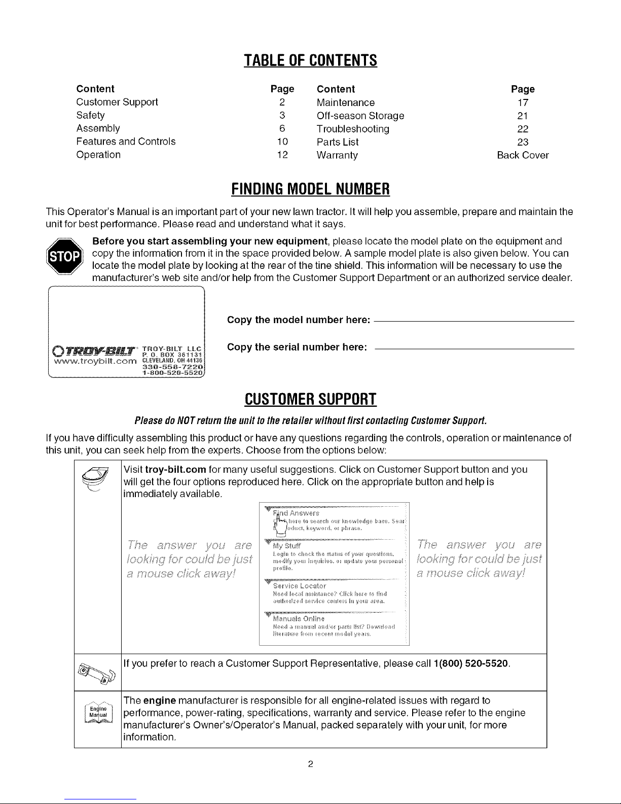
Visit troy-bilt.com for many useful suggestions. Click on Customer Support button and you
will get the four options reproduced here. Click on the appropriate button and help is
immediately available.
_ 7>,,,,
/;/ ,> ;'V }/ )
..... f ; @; t ;D
j;_ ?" #'s " 4t, ' F_ i/!s ,
* ;,, #FOX }_ j,"
,,, >,, rL;," ¢j ,_ <# ft, *x J ,7;; _
'_,-., _tf';_'ivc ,l
,v yO, ,_;7f'_;:'
If you prefer to reach a Customer Support Representative, please call 1(800) 520-5520.
The engine manufacturer is responsible for all engine-related issues with regard to
performance, power-rating, specifications, warranty and service. Please refer to the engine
manufacturer's Owner's/Operator's Manual, packed separately with your unit, for more
information.
Page 3
SECTION1: SAFETY
This machine meets voluntary safety stan-
dard B71.8-1996, which is sponsoredbythe
Outdoor Power Equipment Institute, Inc.,
and is published by the American National
Standards Institute.
WARNING
The engine exhaust from this productcontains
chemicals known to the State of California to
cause cancer, birth defects or other reproduc-
SafetyAlertSymbol
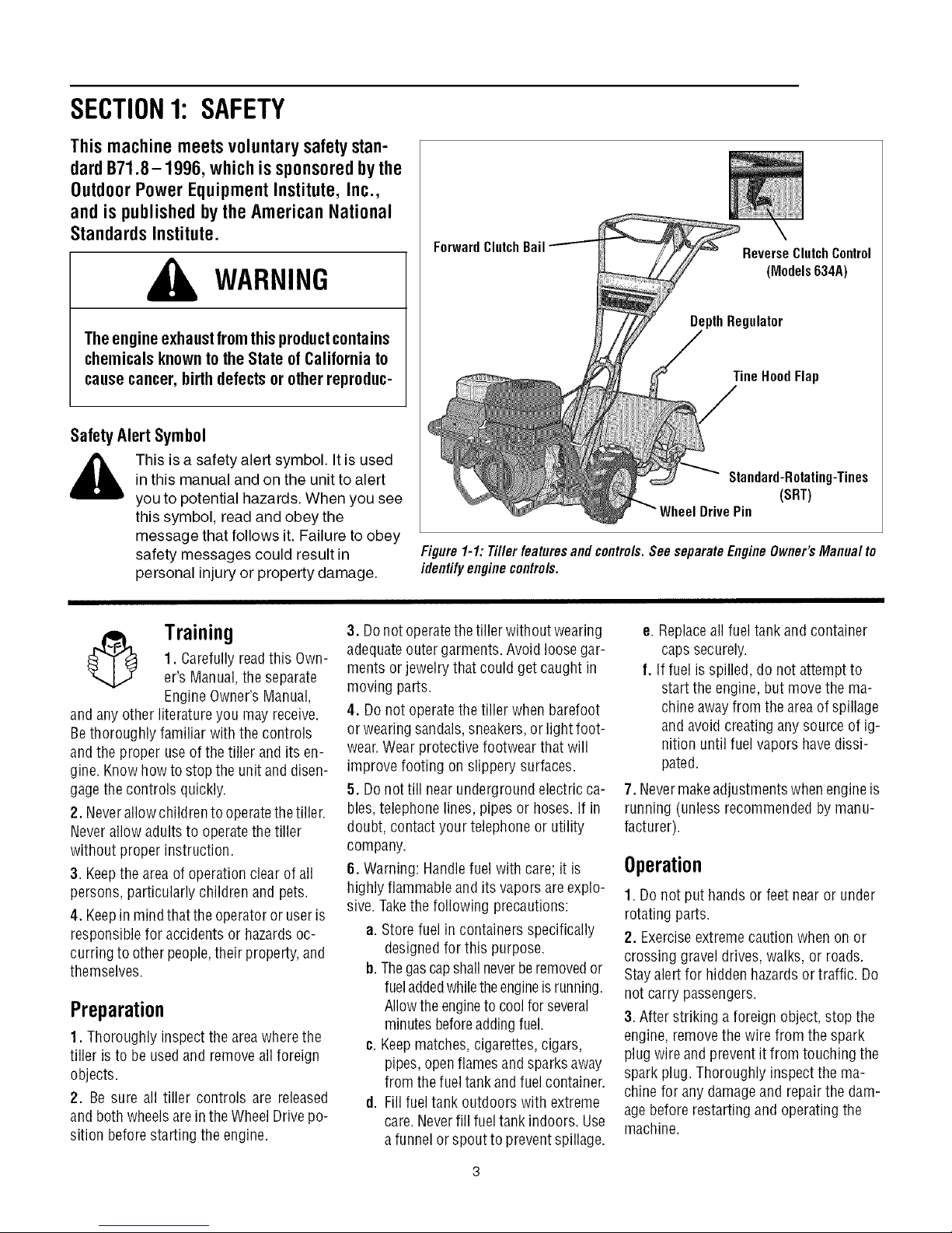
ForwardClutchBail
ReverseClutchControl
(Models634A)
DepthRegulator
TineHoodFlap
,_ This is a safety alert symbol. It is used
and anyother literatureyou may receive.
Bethoroughly familiar withthe controls
andthe proper useof the tiller and its en-
gine. Know howto stopthe unit anddisen-
gagethe controls quickly.
2. Neverallow childrento operatethetiller.
Neverallow adults to operatethe tiller
without proper instruction.
3. Keepthe areaof operation clear of all
persons, particularly children and pets.
4. Keepin mindthattheoperatoror useris
responsible for accidents or hazardsoc-
curring to otherpeople,their property,and
themselves.
in this manual and on the unit to alert
you to potential hazards. When you see
this symbol, read and obey the
message that follows it. Failure to obey
safety messages could result in
personal injury or property damage.
3. Donot operatethetiller without wearing
1. Carefully readthis Own-
Training
er's Manual,the separate
Engine Owner'sManual,
adequateouter garments. Avoid loose gar-
ments or jewelry that could get caught in
moving parts.
4. Donot operatethe tiller when barefoot
or wearingsandals, sneakers,or light foot-
wear.Wear protective footwear thatwill
improve footing onslippery surfaces.
5. Donottill nearunderground electricca-
bles,telephone lines, pipes or hoses.If in
doubt, contactyour telephoneor utility
company.
6. Warning: Handlefuel with care; it is
highly flammable and its vapors areexplo-
sive.Takethe following precautions:
a. Store fuel in containers specifically
b. Thegascapshall neverberemovedor
Preparation
1. Thoroughly inspect the areawherethe
tiller is to be usedand removeall foreign
objects.
2. Be sure all tiller controls are released
and bothwheels arein the WheelDrive po-
sition beforestarting the engine.
c. Keepmatches, cigarettes, cigars,
d. Fill fuel tank outdoors with extreme
Standard-Rotating-Tines
(SRT)
DrivePin
Figure 1-1: Tiller featuresand contre/s. See separateEngine Owner'sManua/ to
identifyengine contre/s.
e. Replaceall fueltank andcontainer
caps securely.
f. If fuel is spilled, do not attempt to
start the engine,but movethe ma-
chineawayfrom the areaof spillage
and avoidcreating any sourceof ig-
nition until fuel vapors havedissi-
pated.
7. Nevermakeadjustments whenengineis
running (unless recommendedby manu-
facturer).
Operation
1. Do not put hands or feet near or under
rotating parts.
designedfor this purpose.
fueladdedwhiletheengineisrunning.
Allowthe engineto coolforseveral
minutesbeforeaddingfuel.
pipes, openflamesand sparks away
from thefueltankandfuelcontainer.
care.Neverfill fuel tank indoors.Use
a funnelor spout to preventspillage.
2. Exerciseextremecaution when onor
crossing gravel drives,walks, or roads.
Stayalert for hiddenhazardsortraffic. Do
not carry passengers.
3. After striking a foreign object, stop the
engine,removethe wire from the spark
plug wire and prevent it from touchingthe
spark plug. Thoroughly inspectthe ma-
chine for any damageand repairthe dam-
agebefore restarting andoperatingthe
machine.
Page 4
4.Exercisecautiontoavoidslippingorfall-
ing.
5.Iftheunitshouldstarttovibrateabnor-
mally,stoptheengine,disconnectthe
sparkplugwireandpreventitfromtouch-
ingthesparkplug,andcheckimmediately
forthecause.Vibrationisgenerallya
warningoftrouble.
6. Stop the engine, disconnectthe spark
plug wire and prevent it from touching the
spark plug,wheneveryou leavethe operat-
ing position, beforeunclogging thetines,
or whenmaking any repairs,adjustments
or inspections.
7. Takeall possible precautions whenleav-
ing the machine unattended.Stopthe en-
gine. Disconnect thespark plug wire and
move it awayfrom thespark plug. Besure
that both wheelsarein theWheelDrive po-
sition.
8. Beforecleaning,repairing,or inspect-
ing, stop the engineand make certain all
moving partshavestopped. Disconnect
the spark plug wire and preventit from
touching thespark plug to preventacci-
dentalstarting.
9. The flapon the fine hood must bedown
when operating thetiller.
10. Neverusethetiller unless proper
guards, plates,or other safetyprotective
devicesare in place.
11. Donot run the enginein an enclosed
area.Engineexhaust containscarbon
monoxide gas, a deadlypoison that is
odorless, colorless, and tasteless.
12. Keepchildren and pets away.
13. Never operate thetiller underengine
powerif thewheels are in theFreewheel
position.In the Freewheelposition, the
wheelswill not holdthe tiller back andthe
revolvingtines could propel the tiller rapid-
ly,possibly causingloss of control. Always
engagethe wheels with the wheel drive
pins in theWheel Drive position before
starting the engineorengaging the
tines4Nheelswith the ForwardClutch Bail
(all models)orthe ReverseClutchcontrol
(Models 634Aonly).
14. Be awarethat the tiller may unex-
pectedlybounceupwardorjumpforward
if the tines shouldstrikeextremelyhard
packedsoil, frozenground,or buried ob-
stacleslike large stones,roots,or
stumps.
If indoubtaboutthetilling conditions, al-
ways usethe following operating precau-
tionsto assistyouin maintainingcontrol
of the tiller:
a. Walk behindandto one side of the
tiller, usingone handonthehandle
barsRelax yourarm, but use a
securehandgrip.
b. Useshallower depthregulator
settings,working graduallydeeper
with eachpass.
¢. Use slowerenginespeeds.
d. Clearthe tilling area of all large
stones,rootsorother debris.
e. Avoidusingdownwardpressureon
thehandlebars. If needbe, use
slight upwardpressuretokeep the
tinesfrom diggingtoodeeply.
f. Beforecontacting hardpackedsoil
at the endof a row,reduce engine
speedand lift thehandlebarsto
raise thetines out of the soil.
g. In anemergency,stopthetinesand
wheels byreleasing whichever
clutch controlis engaged.Donot
attemptto restrainthetiller.
15. Donot overloadthe tiller's capacityby
attempting to till too deeplyat too fast a
rate.
16. Neveroperatethetiller at hightrans-
port speeds on hard or slippery surfaces.
Look behind and use carewhen backing
up.
17. Donot operatethetiller on aslope that
is too steepfor safety. When on slopes,
slow down and makesure you havegood
footing. Neverpermit thetillerto freewheel
down slopes.
18. Neverallow bystandersnearthe unit.
19. Onlyuseattachmentsand accessories
that areapproved bythe manufacturer of
the tiller.
20. Usetiller attachmentsand accessories
when recommended.
21. Neveroperatethetiller without good
visibility or light.
22. Neveroperatethe tiller if you aretired;
or underthe influence ofalcohol, drugs or
medication.
23. Operatorsshall nottamper with theen-
gine-governor settings onthe machine;
the governor controls the maximum safe
operatingspeedto protectthe engine and
all movingparts from damagecaused by
overspeed.Authorized service shall be
sought if a problem exists.
24. Do nottouch enginepartswhich may
behot from operation.Letpartscool down
sufficiently.
25. Pleaseremember:Youcan alwaysstop
thetines and wheels by releasingthe For-
ward Clutch Bail or on Model634Athe Re-
verseClutchcontrol, (whichevercontrol is
engaged),or by moving the ignition switch
and/orthrottle control leveron the engine
to "OFF" or "STOP".
26. Toloador unloadthe tiller, seethe in-
structions in Section4 of this Manual.
27. Useextremecautionwhen reversing
or pullingthe machinetowards you.
28. Startthe enginecarefully accordingto
instructions and with feet well awayfrom
thetines.
29. Neverpick up or carry a machinewhile
the engineis running.
MaintenanceandStorage
1. Keepthe tiller, attachmentsand acces-
sories in safeworking condition.
2. Checkall nuts, bolts, and screwsfor
proper tightness to besurethe equipment
is in safeworking condition.
3. Neverstore thetiller with fuel inthe fuel
tank insidea building where ignition sourc-
esare presentsuchashot waterandspace
heaters,furnaces, clothes dryers, stoves,
electric motors, etc.). Allow the engineto
cool before storing the unit in any enclo-
sure.
4. Toreducethe chancesof a fire hazard,
keepthe enginefreeofgrass, leaves,or ex-
cessivegrease.
5. Storegasolinein acool, well-ventilated
area,safely awayfrom anyspark- or
flame-producing equipment. Store gaso-
line in anapprovedcontainer,safelyaway
from the reachof children.
6. Referto the Maintenancesections of
this Manualand the separateEngineOwn-
er'sManualfor instructions ifthe unit is to
bestored for an extendedperiod.
7. Neverperform maintenancewhilethe
engineis running orthe spark plug wire is
connected,exceptwhen specifically in-
structed to do so.
8. Ifthe fueltank hasto bedrained,dothis
outdoors.
Page 5
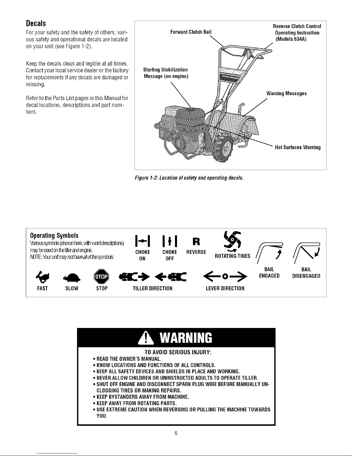
Decals
Foryour safetyandthe safety of others, vari-
ous safety and operational decalsare located
on your unit (seeFigure 1-2).
Keepthe decalscleanand legibleatall times.
Contactyour local servicedealeror thefactory
for replacementsif anydecalsaredamagedor
missing.
Referto the PartsListpagesin this Manualfor
decallocations, descriptions and part num-
bers.
ForwardClutchBail
StartingStabilization
Message(on engine)
Figure 1-2: Locationofsafety and operatingdeca/s.
ReverseClutch Control
OperatingInstruction
(Models 634A)
WarningMessages
HotSurfacesWarning
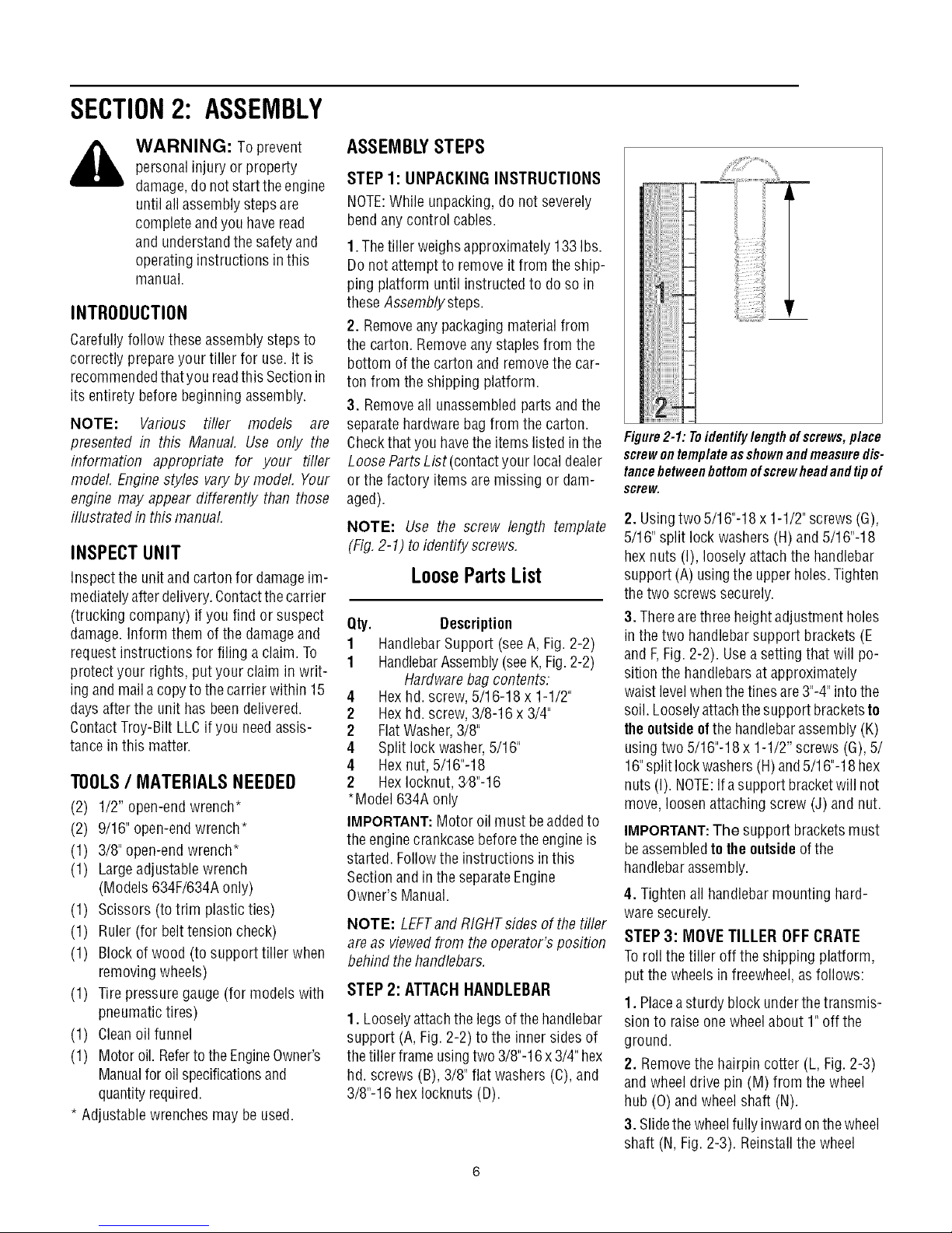
OperatingSymbols
Varioussymbols(shownhere,withworddescriptions)
mayheusedonte'dllerandengine.
NOTE:Yourunitmaynothaveallof_esymbds.
FAST SLOW STOP
* READTHEOWNER'SMANUAL.
* KNOWLOCATIONSAND FUNCTIONSOFALLCONTROLS.
* KEEPALLSAFETYDEVICESANDSHIELDSIN PLACEAND WORKING.
° NEVERALLOWCHILDRENORUNINSTRUCTEDADULTSTOOPERATETILLER.
° SHUTOFFENGINEAND DISCONNECTSPARKPLUGWIREBEFOREMANUALLYUN-
CLOGGINGTINESORMAKINGREPAIRS.
° KEEPBYSTANDERSAWAYFROM MACHINE.
° KEEPAWAYFROM ROTATINGPARTS.
° USEEXTREMECAUTIONWHENREVERSINGOR PULLINGTHEMACHINETOWARDS
YOU.
I"1 I*1 R
CHOKE CHOKE REVERSE
ON OFF ROTATINGTINES
<,-K,
TILLERDIRECTION
TO AVOID SERIOUS INJURY:
<--o-->
LEVERDIRECTION
BAIL
ENGAGED
BAIL
DISENGAGED
Page 6
SECTION2: ASSEMBLY
WARNING: Toprevent
personalinjury or property
damage,do notstartthe engine
until all assemblysteps are
completeandyou haveread
and understandthesafety and
operatinginstructions in this
manual.
INTRODUCTION
Carefullyfollow these assemblysteps to
correctly prepareyour tiller for use. It is
recommendedthatyou readthis Sectionin
its entirety beforebeginning assembly.
NOTE: Various rifler models are
presented in this Manual. Use only the
information appropriate for your tiller
model. Enginestyles varyby model, Your
engine may appear differently than those
illustrated in this manual.
INSPECTUNIT
Inspect the unit and carton for damageim-
mediatelyafter delivery.Contactthe carrier
(trucking company) if you find orsuspect
damage. Inform them of the damageand
request instructions for filing a claim. To
protect your rights, put your claim in writ-
ing and maila copyto the carrierwithin 15
days after the unit has beendelivered.
ContactTroy-Bilt LLCif you needassis-
tance inthis matter.
TOOLS/ MATERIALSNEEDED
(2) 1/2" open-end wrench*
(2) 9/16" open-endwrench*
(1) 3/8" open-endwrench*
(1) Largeadjustable wrench
(Models 634F/634A only)
(1) Scissors (totrim plasticties)
(1) Ruler (for belttension check)
(1) Block of wood (to support tiller when
removing wheels)
(1) Tirepressure gauge (for models with
pneumatictires)
(1) Cleanoil funnel
(1) Motor oil. Refertothe EngineOwner's
Manualfor oilspecificationsand
quantityrequired.
* Adjustable wrenches may be used.
ASSEMBLYSTEPS
STEP 1: UNPACKING INSTRUCTIONS
NOTE:While unpacking,do not severely
bend anycontrol cables.
1.The tiller weighs approximately 133 Ibs.
Do not attempt to remove it from the ship-
ping platform until instructed to do so in
these Assembly steps.
2. Removeany packagingmaterial from
the carton. Removeany staples from the
bottom of the carton and removethe car-
ton from the shipping platform.
3. Removeall unassembledparts andthe
separatehardwarebag from the carton.
Checkthat you havethe items listed in the
LooseParts List (contactyour local dealer
or the factory items are missing or dam-
aged).
NOTE: Use the screw length template
(Fig,2-1) to identify screws,
LoosePartsList
Qty. Description
1 HandlebarSupport (seeA, Fig. 2-2)
1 HandlebarAssembly(seeK,Fig.2-2)
Hardwarebag contents:
4 Hexhd. screw, 5/16-18 x 1-1/2"
2 Hexhd. screw, 3/8-16 x 3/4"
2 FlatWasher,3/8"
4 Split lockwasher,5/16"
4 Hexnut, 5/16"-18
2 HexIocknut, 34}"-16
*Model 634Aonly
IMPORTANT:Motor oil must beaddedto
the enginecrankcasebeforetheengine is
started. Followthe instructions inthis
Sectionand in the separateEngine
Owner's Manual.
NOTE: LEFTandRIGHTsidesof thetiller
are as viewedfrom the operator's position
behind thehandlebars.
STEP 2: ATTACHHANDLEBAR
1. Looselyattachthe legsof thehandlebar
support (A, Fig. 2-2) to the inner sides of
the tiller frameusingtwo 3/8"-16x 3/4" hex
hd. screws (B), 3/8" flat washers(C), and
3/8"-16 hex Iocknuts (D).
_iiii
Figure2-1: Toidentifylengthofscrews,place
screwontemplateasshownandmeasuredis-
tancebetweenbottomofscrewheadandtipof
screw.
2. Usingtwo 5/16"-18 x 1-1/2"screws (G),
5/16" split lock washers (H) and 5/16"-18
hexnuts (I), loosely attachthe handlebar
support (A)usingthe upperholes.Tighten
thetwo screws securely.
3. Therearethree height adjustment holes
in the two handlebar support brackets (E
and F,Fig. 2-2). Usea setting thatwill po-
sition the handlebarsat approximately
waist levelwhenthe tines are3"-4"into the
soil. Looselyattachthe support bracketsto
theoutsideofthe handlebarassembly (K)
usingtwo 5/16"-18x 1-1/2" screws (G),5/
16"split lockwashers (H)and5/16"-18 hex
nuts (I).NOTE:Ifa support bracketwill not
move, loosen attaching screw (J) and nut.
IMPORTANT:The support bracketsmust
beassembledto theoutsideof the
handlebarassembly.
4. Tightenall handlebarmounting hard-
waresecurely.
STEP 3: MOVE TILLER OFF CRATE
Toroll the tiller off the shipping platform,
put the wheelsinfreewheel,asfollows:
1. Placeasturdy block underthetransmis-
sion to raiseone wheel about 1"off the
ground.
2, Removethe hairpin cotter (L, Fig.2-3)
and wheeldrive pin (M) from the wheel
hub (0) and wheelshaft (N).
3. Slidethe wheelfully inwardonthe wheel
shaft (N, Fig.2-3). Reinstall the wheel
Page 7
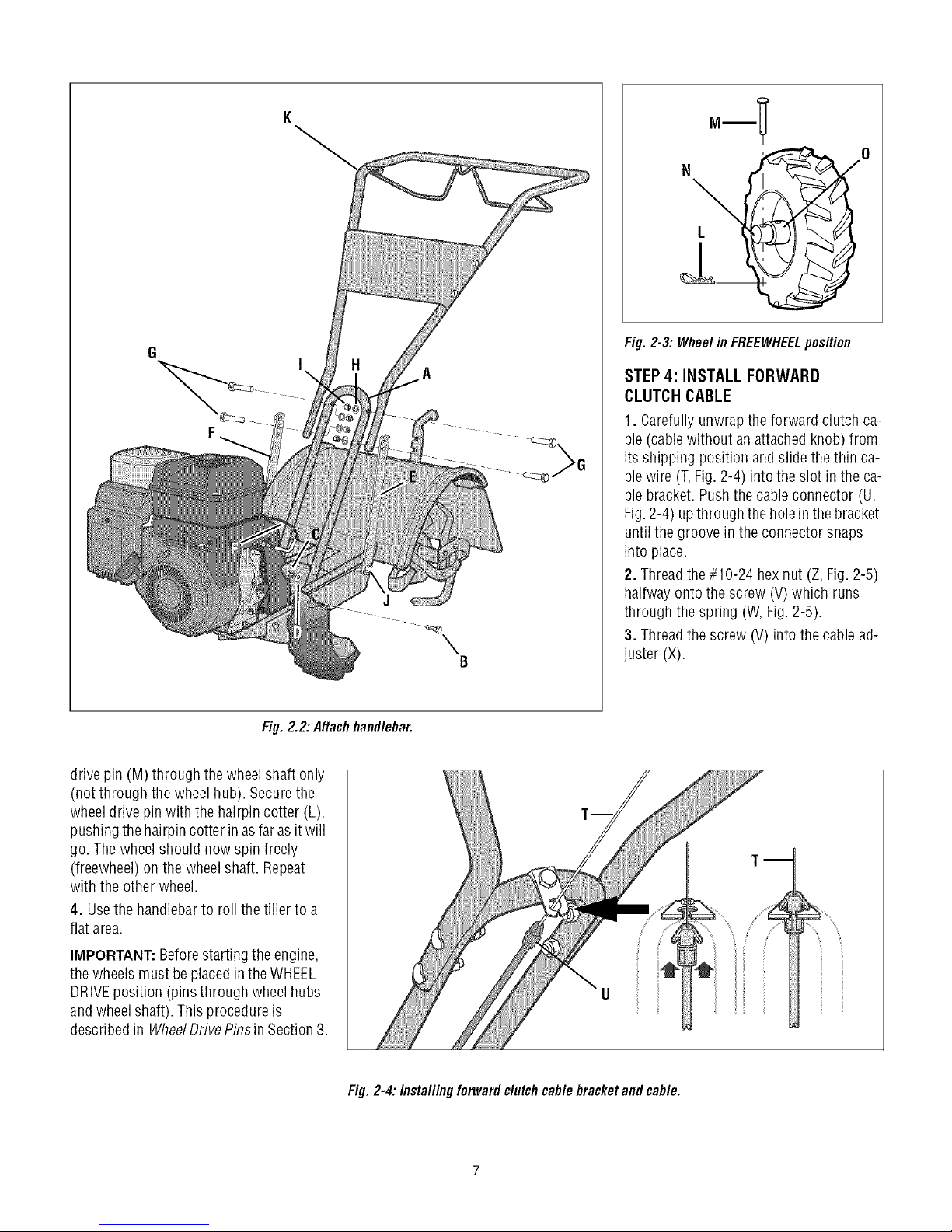
°-! °
Fig. 2-3: Wheel in FREEWHEELposition
Fig. 2.2: Attachhandlebar.
drive pin (M) through thewheel shaft only
(not through the wheel hub). Securethe
wheeldrive pinwith the hairpin cotter (L),
pushingthe hairpincotter in asfarasit will
go. The wheelshould now spin freely
(freewheel) on the wheel shaft. Repeat
with the other wheel.
4. Usethe handlebarto roll the tiller to a
flat area.
A
J
B
STEP 4: INSTALL FORWARD
CLUTCH CABLE
1. Carefullyunwrapthe forward clutch ca-
ble(cablewithout an attachedknob) from
its shipping position and slide thethin ca-
blewire (T,Fig. 2-4) into the slot in the ca-
blebracket. Pushthe cableconnector (U,
Fig.2-4) upthrough the holein the bracket
untilthe groove in the connector snaps
into place.
2. Threadthe#10-24 hexnut (Z, Fig. 2-5)
halfway onto the screw (V) which runs
through the spring (W, Fig.2-5).
3. Threadthe screw (V) into the cable ad-
juster (X).
IMPORTANT: Beforestartingthe engine,
the wheels must beplacedin theWHEEL
DRIVEposition (pinsthrough wheelhubs
andwheelshaft). This procedureis
describedin WheelDrivePinsin Section3.
Fig. 2-4: Installingforward clutchcable bracketand cable.
Page 8
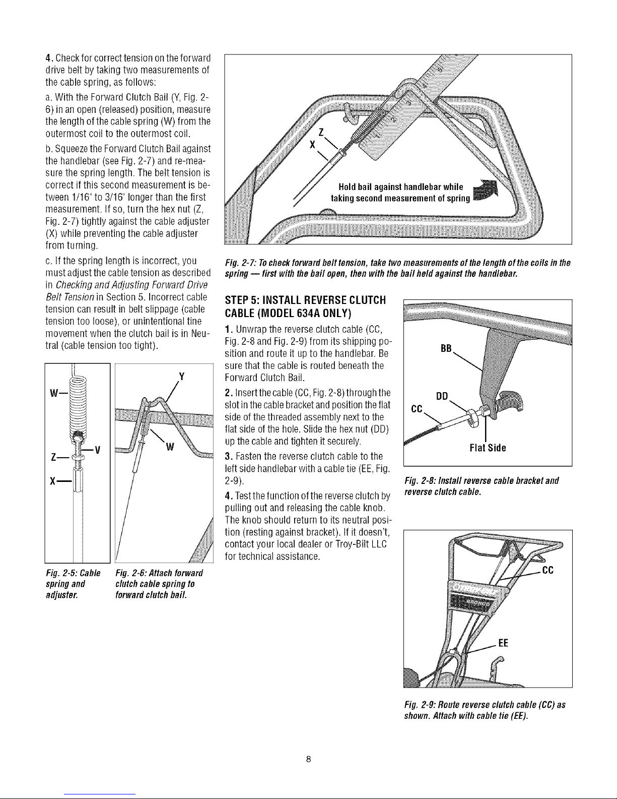
4. Checkfor correct tension ontheforward
drive belt bytaking two measurementsof
the cable spring, as follows:
a.With the ForwardClutch Bail(Y,Fig. 2-
6) in an open (released)position, measure
the length ofthecablespring (W) from the
outermost coil to the outermost coil.
b. Squeezethe ForwardClutch Bailagainst
the handlebar(seeFig.2-7) andre-mea-
surethe spring length. Thebelt tension is
correct if this second measurementis be-
tween 1/16"to 3/16" longerthanthe first
measurement.If so, turn the hexnut (Z,
Fig. 2-7) tightly against the cableadjuster
(X) while preventingthe cableadjuster
from turning.
c. Ifthe spring lengthis incorrect, you
must adjustthe cabletension asdescribed
in Checkingand Adjusting Forward Drive
Belt Tensionin Section5. Incorrect cable
tension can result in beltslippage (cable
tension too loose), or unintentional tine
movement whenthe clutch bail is in Neu-
tral (cabletension too tight).
Wm
W
iiiiiiiiiiiiiiii
Fig. 2-7: Tocheckforwardbelt tension, take twomeasurementsofthelengthofthe coils inthe
spring-- first withthebail open, then withthe bail held against thehandlebar.
STEP 5: INSTALL REVERSECLUTCH
CABLE (MODEL 634A ONLY)
1. Unwrapthe reverseclutch cable (CC,
Fig.2-8 andFig.2-9) from its shipping po-
sition androute it up to the handlebar.Be
surethat the cableis routedbeneaththe
Forward Clutch Bail.
2. Insertthecable(CC,Fig.2-8)through the
slot inthecablebracketandpositiontheflat
sideof thethreadedassemblynextto the
flat side of the hole.Slidethe hex nut (DD)
up thecable andtighten it securely.
Flat Side
3. Fastenthe reverseclutch cable to the
left sidehandlebarwith acabletie (EE,Fig.
2-9).
4. Testthefunction ofthe reverseclutch by
Fig. 2-8:/nsta//reverse cablebracketand
reverseclutchcable.
pulling out and releasingthe cableknob.
Theknob should return to itsneutral posi-
tion (resting against bracket). Ifit doesn't,
contact your local dealeror Troy-Bilt LLC
for technical assistance.
Fig.2-5: Cable
springand
adjuster.
Fig. 2-6: Attach forward
clutchcable spring to
forwardclutch bail.
Fig. 2-9: Route reverseclutchcable(CC)as
shown.Attachwithcable tie(EE).
Page 9
5! 6: CHECKTRAHSMiSSiOH
OILLEVEL
Thetransmission wasfilledwith gearoil at
thefactory. However,you shouldcheckthe
gear oil levelat this timeto makecertain it
is correct.
IMPORTANT:Donot operatethetiller if the
gear oil level is low. Doingso will result in
severedamageto the transmission com-
ponents.
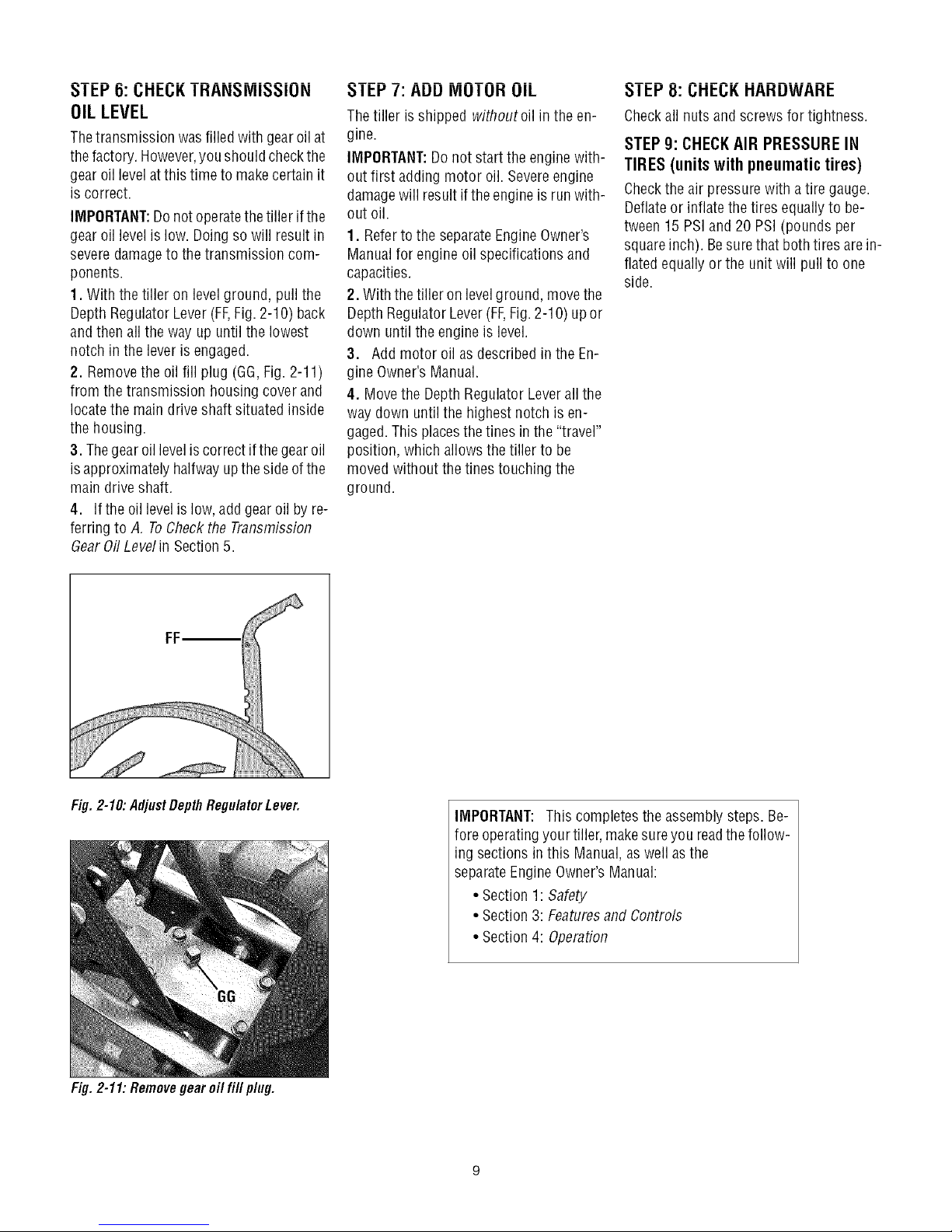
1. With the tiller on levelground, pull the
Depth RegulatorLever(FF,Fig. 2-10) back
andthen all theway up until the lowest
notch inthe lever isengaged.
2. Removethe oil fill plug (GG,Fig.2-11)
from the transmission housing cover and
locatethe maindrive shaft situated inside
the housing.
3. Thegear oil levelis correct if thegear oil
isapproximately halfway upthe sideofthe
main drive shaft.
4. Ifthe oil levelislow, add gear oil by re-
ferring to A. ToCheckthe Transmission
dear 0il Levelin Section5.
I El-'/: AUU IVlUI UH UIL
Thetiller isshipped withoutoil in the en-
gine.
IMPORTANT:Donot start the enginewith-
out first adding motor oil. Severeengine
damagewill result ifthe engineis run with-
out oil.
1. Referto the separateEngineOwner's
Manualfor engine oil specifications and
capacities.
2. With the tiller on levelground, movethe
Depth RegulatorLever(FF,Fig.2-1O)upor
down until the engine is level.
3. Add motor oil as describedin the En-
gine Owner's Manual.
4. Movethe DepthRegulator Lever all the
way down untilthe highest notch is en-
gaged.This placesthe tines in the"travel"
position, which allows the tiller to be
moved without thetines touching the
ground.
_1 El-'8: I.;HEI.;K HAHUWAHE
Checkall nuts and screws for tightness.
STEP g: CHECKAIR PRESSURE IN
TIRES (unitswithpneumatictires)
Checkthe air pressurewith a tire gauge.
Deflateor inflatethe tires equally to be-
tween 15 PSIand 20 PSI (pounds per
squareinch). Besurethat bothtires arein-
flated equallyor the unit will pull to one
side.
Fig. 2-10: AdjustDepth RegulatorLever.
Fig. 2-11: Removegear oil fill plug.
IMPORTANT: This completesthe assemblysteps. Be-
fore operatingyour tiller, makesure you readthe follow-
ing sectionsinthis Manual,as well asthe
separateEngineOwner'sManual:
• Section1: Safety
• Section3: Featuresand Controls
• Section4: Operation
Page 10
SECTION3: FEATURESANDCONTROLS
_ ARNING: Before
operatingyour machine,
carefully readand understand
all safety,controls and
operatinginstructions in this
Manual,the separateEngine
Owner's Manual,and on the
decalson the machine.
Failureto follow these
instructions can resultin
serious personalinjury.
INTRODUCTION
This Section describesthe locationand
function of thecontrols onyourtiller. Refer
to the following Section, Operationfor de-
tailed operatinginstructions.
Practice using these controls, with the en-
gine shut off, until you understandthe op-
eration of the controls and feelconfident
with eachof them.
ENGINE CONTROLS
Referto the enginemanufacturer'sEngine
Owner'sManual(included in the tiller liter-
aturepackage)to identify the controls on
your engine.
IMPORTANT:Thecontrol for stopping the
engine is located onthe engine.
WHEEL DRIVE PINS
Eachwheel is equippedwith a wheeldrive
pin (A, Figures3-2 and 3-3) that secures
the wheel to the wheelshaft (B). The
wheelscan be positioned in either a
WHEELDRIVEor a FREEWHEELmode.
_ WARNING: Neverallow
either of thewheelsto bein the
FREEWHEELposition whenthe
engineis running. Alwaysput
both wheelsin the WHEEL
DRIVEposition before starting
the engine.
Failureto comply could cause
loss of tiller control, property
damage,or personalinjury.
Beforestarting the engine,put both wheels
in the WHEELDRIVEposition byinserting
the wheel drive pins through the wheel
hubsandthewheelshaft. Doingso "locks"
the wheels to the wheel shaft, causing the
wheelsto turn when either the
ForwardClutch
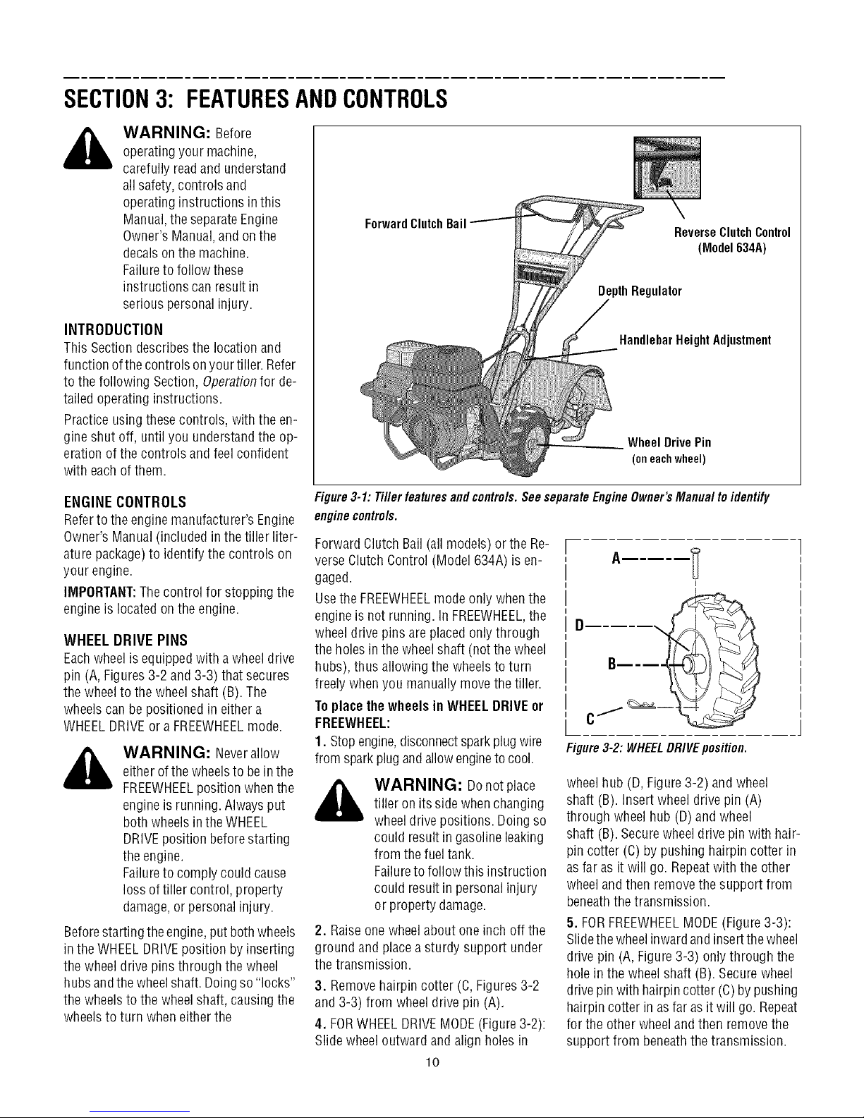
Figure3-1: Tiller features and controls.See separateEngineOwner's Manual toidentify
enginecontrols.
Bail ReverseClutchControl
(Model 634A)
gulator
HandlebarHeight Adjustment
Wheel Drive Pin
(oneachwheel)
Forward ClutchBail (all models) or the Re-
verse ClutchControl (Model 634A)is en-
gaged.
Usethe FREEWHEELmode only whenthe
engineis not running, in FREEWHEEL,the
wheeldrive pins are placedonly through
the holes inthewheelshaft (notthe wheel
hubs), thus allowing the wheelsto turn
freely whenyou manually movethe tiller.
Toplacethewheels in WHEELDRIVEor
FREEWHEEL:
1. Stopengine,disconnectsparkplug wire
Figure3-2: WHEELDRIVEposition.
from sparkplug andallowengineto cool.
wheelhub (D, Figure3-2) andwheel
_ WARNING: Donotplace
tiller on its sidewhen changing
wheeldrive positions. Doingso
could result in gasoline leaking
from the fuel tank.
Failureto follow this instruction
could result in personalinjury
or propertydamage.
2. Raiseone wheelabout one inch off the
ground andplaceasturdy support under
the transmission.
shaft (B). Insertwheel drive pin (A)
through wheel hub (D)and wheel
shaft (B). Securewheeldrive pin with hair-
pin cotter (C) by pushing hairpincotter in
asfar as it will go. Repeatwith the other
wheeland then removethe support from
beneaththe transmission.
5. FORFREEWHEELMODE(Figure 3-3):
Slidethewheelinwardandinsertthewheel
drive pin (A, Figure3-3) onlythrough the
hole in the wheel shaft (B). Securewheel
3. Removehairpin cotter (C,Figures3-2
and 3-3) from wheel drive pin (A).
4. FORWHEELDRIVEMODE(Figure3-2):
Slide wheeloutward and align holes in
lO
drivepin with hairpincotter (C) bypushing
hairpin cotter in asfar as it will go. Repeat
for the other wheeland then removethe
support from beneaththetransmission.
Page 11

_--'i_ caution whenreversing or
A
Y
,,_- D you. Look behindto avoid
Figure3-3:FREEWHEELposition.
engine,besurethat both the ground, look behind you to avoid any
WARNING: Beforestarting 3. Lift the handlebar untilthe tines clear
wheelsare inWHEELDRIVE obstacles,and then pullthe control knob
position. SeeWheelsDrivePins (F,Figure3-4) out. The wheels and tines
for instructions, will rotate in a reversedirection.
Engagingthe Forward Clutch 4. Releasethe control knob to disengage
Bail or ReverseClutch Control (stop)the wheels andtines (theenginewill
(if equipped) when thewheels continue to run).
arenot in WHEELDRIVEcould
allowthe tinesto rapidly propel
the tiller forward or backward.
Failureto comply could cause
loss of tiller control, property
damage,or personalinjury.
FORWARDCLUTCHBAIL
TheForward Clutch Bail(E, Figure3-4)
controls the engagementof forward drive F
to the wheelsand tines. E
Tooperate the ForwardClutchBail:
1. Put wheelsin WHEELDRIVEposition Figure3-4:AIImodelshavea ForwardClutch
(see"WARNING"statement above). Bail(E).OnlyMode1634AhaveaReverse
2. Lift and hold the clutch bail (E,Figure3-
4)againstthehandlebartostartthewheels DEPTH REGULATOR LEVER
andtines rotating in aforward direction.
3. Releasethe clutch bail to disengage ing depth of the tines. Pullthe lever back
(stop) thewheels andtines (theenginewill and slide it up or downto engagethe
continue to run). notched height settings.
REVERSECLUTCHCONTROL The"travel position" (highestnotch) raises
(Model 634A only) the tines approximately1-1/2"offthe
TheReverseClutchControl (F,Figure3-4) without the tines contacting the ground.
controls the engagementof reversedrive Thissetting should also beused when
to the wheelsandtines.The reversingfea- starting the engine.
ture isusedfor maneuveringthe tiller
only-- neverengage thetines in the Moving the leverupward will increasethe
ground while operatingin reverse.
_ WARNING: Useextreme
pulling the machinetowards
obstacles.
Neverattemptto till in reverse.
Failureto follow thiswarning
could result in personalinjury
or propertydamage.
Tooperatethe ReverseClutchControl:
1. Putwheelsin WHEELDRIVEposition
(see"WARNING"statement at the left).
2. Stopall tiller motion by releasingthe
Forward Clutch Bail.
ClutchControl(F).
This lever (G, Figure3-5) controls the till-
ground, allowing the tiller to be moved
tilling depth.The lowest notch allows atill-
ing depthof approximately6", depending
on soil conditions. For best results,always
begintilling ataveryshallowdepthsetting
and gradually increasethe tilling depth.
_b ARNING: Donotattempt
TravelPosition
Figure3-5: DepthRegulator Lever (G).
HANDLEBARHEIGHT ADJUSTMENT
Thehandlebarheight isadjustabletothree
different settings (Figure3-6). In general,
adjust the handlebars sothey areat waist
levelwhen the tines are3"-4"in the soil.
Toadjustthe handlebars:
1. Stop engine,disconnectspark plugwire
from sparkplug andallow engineto cool.
2. Removehardware,reposition handle-
bars,and reinstall hardwaresecurely.
Figure3-6: Handlebarheightadjustment.
to till too deeplytoo quickly.
Graduallywork downto deeper
tilling depths.
Placethe DepthRegulator
Leverin the "travel" position
beforestarting theengine.This
position preventsthetinesfrom
touching the ground untilyou
are readyto begintilling.
Failureto follow thiswarning
could result in personalinjury
or propertydamage.
High
Medium
11
Page 12

SECTION4: OPERATION
_ ARNING: Before
operatingyour machine,
carefully readand understand
all safety (Section 1),controls
(Section 3) and operating
instructions (Section4) inthis
Manual,the separateEngine
Owner's Manual,and on the
decalson the machine.
Failureto follow these
instructions can resultin
serious personalinjury.
INTRODUCTION
Readthis OperationSection andthe sepa-
rate EngineOwner'sManualbeforeyou
start the engine.Then,take thetime to fa-
miliarize yourself with the basicoperation
of the tiller before using it in the garden.
Findan open, levelareaand practice using
the tiller controls without thetines engag-
ing the soil (put tines in "travel" setting).
Onlyafter you've becomecompletely fa-
miliar with the tiller shouldyou beginusing
it in the garden.
BREAK-INOPERATION
Perform the following maintenanceafter
the first two (2) hours of new operation
(see MaintenanceSection in this manual
and in the Engine Owner'sManual).
1. Changeengineoil.
2. Checkfor loose or missinghardwareon
unit. Tightenor replaceas needed.
3. Checktension onforward drive belt.
4. Checktransmission gear oil level.
STARTING AND STOPPING
Pre-StartChecklist
With the spark plug wire disconnected
from the sparkplug, performthe following
checksand services beforeeachuse:
1. Readthe Safetyand Controls Sections
in this manual. Readthe separateEngine
Owner's Manualprovidedwith the unit.
2. Putthe wheels inthe WHEELDRIVEpo-
sition (wheel pins must be through holes
in wheelhubs andwheel shaft).
3. Checkunit for loose or missing hard-
ware. Serviceas required.
4. Checkengineoil level.SeeEngineOwn-
er's Manual.
ReverseClutchControl
(Model634A)
ClutchBail
,epthRegulator
/
DrivePin
Fig. 4-1
5. Checkthat allsafety guards andcovers
are in place.
6. Checkair cleanerand engine cooling
system. SeeEngineOwner's Manual.
,_ WARNING: GASOLINEIS
7. Fill thefuel tank with gasolineaccording
to the directions inthe separate Engine
Owner's Manual.Follow all instructions
and safety rules carefully.
8. Attachsparkplug wire to spark plug.
Startingthe Engine
Thefollowing steps describehow to start
and stop the engine.
,_ WARNING: Donotattempt
HIGHLYFLAMMABLEAND ITS
VAPORSAREEXPLOSIVE.
Followgasolinesafety rules in
this Manual(seeSection 1)and
in theseparateEngineOwner's
Manual.
Failureto follow gasolinesafety
instructions can resultin
serious personalinjury and
property damage.
to engagethetines orwheels
until you havereadall ofthe
operatinginstructions in this
Section.Also, reviewthe safety
rules in Section 1: Safety,and
the tiller andenginecontrols
information in Section3:
Featuresand Controls.
1. Completethe Pre-StartCheckliston this
page.
2. Putthe wheels inthe WHEELDRIVEpo-
sition (seeWheelDrivePinsin Section3 of
this manual).
,_ WARNING: Tohelp
• Before starting engine, put both
wheels in the WHEELDRIVEposition.
Never havewheels in FREEWHEELpo-
sition when engine is running.When
thewheels are in FREEWHEEL,theydo
not hold backthe tiller and the tines
couldpropelthe tiller rapidly
forwardor backward.
• Before starting engine, put Forward
Clutch Bail (all models) and Reverse
Clutch Control (Model 634A only) in
neutral (disengaged) positionsby re-
leasinglevers.
• Never run engine indoors or in en-
closed,poorlyventilatedareas. Engine
exhaustcontainscarbonmonoxide,an
odorlessanddeadlygas.
• Avoidenginemuffler andnearbyareas.
Temperaturesin these areas may ex-
ceed 150° F.
3. Movethe Depth RegulatorLever all the
way down to the "travel" position, so that
thetines clearthe ground.
4. Releaseall controls on the tiller.
5. Onengine's with afuel shut-off valve,
turn valve to openposition, asinstructed
in the separateEngine Owner'sManual.
6. Put ignition switch and/or throttle con-
trol leverlocatedonengine in the "ON",
"RUN", "FAST"or "START"position, as in-
structed inthe EngineOwner's Manual.
7. Chokeor prime engine,as instructed in
EngineOwner's Manual.
8. Put onehand on fuel tank to stabilize
unitwhen pullingstarter ropehandle.Then
userecoil starter to start engine, as in-
structed inthe EngineOwner's Manual.
Whenenginestarts, graduallymove choke
lever (if so equipped) to "NO CHOKE",
"CHOKEOFF"or "RUN" position.
9. Usethe "FAST"throttle speed setting
whentilling.
preventserious personalinjury
or damageto equipment:
12
Page 13

Stopping the EngineandTiller
1. Tostop thewheelsandtines, releasethe
Forward ClutchBail (all models) orthe Re-
verse ClutchControl (Model 634A)--
whichevercontrol is in use.
2. Tostop the engine,put the ignition
switch and/or thethrottle control leverin
the "OFF"or "STOP"position.
OPERATINGTHETILLER
Thefollowing operatinginstructions pro-
videguidelines to using your tiller effec-
tively and safely. Besure to read Tilling
Tips & Techniquesinthis Section before
actually putting the tines into the soil.
NOTE:Thisis atraditional "Standard-Ro-
tating-Tine" (SRT)tiller with forward rotat-
ing tines,it operatescompletely differently
from "Counter-Rotating-Tine"(CRT)tillers
or from front-tine tillers.
1. Followthe Pre-Start Checklistatthe be-
ginning of this Section. Besure that the
wheelsare intheWHEELDRIVEposition.
2. Movethe DepthRegulator Lever all the
way down, so that the tines clearthe
ground. Usethis position when practicing
with thetiller and when traveling between
tilling sites. Beforeactuallytilling, move
the leverto the desireddepth setting (see
Tilling Tips & Techniques).
3. Start engineand allow it to warm up.
Thenput throttle in "FAST"setting.
4. For forwardmotion ofthe wheels and
tines:
(a) PullForwardClutch Bail (Fig.4-1) up
against handlebar.Releasebailto stopfor-
ward motion of wheelsand tines.
(b) Whentilling, relaxand letthe wheels
pull the unit while thetines dig.Walk be-
hind anda little to onesideof the unit.Use
one hand,yet keepa light--but secure--
grip onthe handlebar (while keepingyour
arm loose). SeeFig.4-2. Letthe unit move
at its own paceand do not push down on
the handlebarsto try and forcethe tinesto
dig deeper-- this takes weight offthe
wheels, reducestraction, andcauses the
tines to try and propel the tiller.
,_ WARNING: Donotpush
down onthe handlebarsto try
to makethetiller till more
deeply.This preventsthe
wheelsfrom holdingthe tiller
backand canallow the tines to
rapidly propelthe tiller forward,
which could resultin loss of
control, property damage,or
personalinjury.
5. Forreversemotion ofthe wheelsand
tines (Model634A only):
(a) Lookbehindand exercisecaution when
operating in reverse.Donot till while in
reverse.
(b) Stopall forward motion. Lift handlebar
with one handuntiltines areoff the ground
andthen pull ReverseClutchControl knob
out (seeFig.4-3). Tostop reversing,letgo
of ReverseClutch Control knob.
(b) Swingthe handlebarto theleft so the
right wheeltakesa "step" backward.Next
swing the handlebarto the right so the left
wheel"steps" backward.Repeatasneeded.
(c) If longer distances needto becovered
in reverse,shut off the engine, then place
the two wheels in FREEWHEEL.
7. ToTurnthe Tiller Around:
(a) Practiceturning the tiller in a level,
openarea.Beverycarefulto keepyour feet
and legsaway from the tines.
(b) Tobeginaturn, lift thehandlebarsuntil
thetinesareoutofthegroundandtheengine
andtinesarebalancedoverthe wheels(Fig.
4-4).
(c) With tiller balanced,pushsideways on
handlebarto steer in direction of turn (Fig.
4-5). After turning, slowly lower tines into
soil to resumetilling.
Fig. 4-4: Tobegin turn, lift handlebars until
tines are out of groundand unit is balanced.
Fig.4-2:Useonehandtoguidefillerwhen
movingforward.
Fig.4-3:Raisetinesoffgreundandlook
behindwhenmovinginreverse.
6. Tomovethe Model 630Cin reversefor
short distances:
(a) Releaseforward ClutchBail. Thenlift
handlebaruntiltines are off the ground.
13
Fig.4-5: Withtinesout ofgreund,pushhan-
dlebarssidewaysto turntiller.
StoppingtheTillerandEngine
1. Tostop thewheelsandtines, releasethe
Forward ClutchBail (all models) orthe Re-
verse ClutchControl (Model 634A)--
whichevercontrol is in use.
2. Tostop the engine,put the ignition
switch and/orthe throttle control leverin
the "OFF"or "STOP"position.
Page 14

TILLINGTIPS& TECHNIQUES
Tilling Depths
WAHNINL_: Before
tilling, contactyour
telephoneor utilities
companyand inquire if
undergroundequipment or
lines are usedon your
property. Donottill near
buriedelectric cables,
telephonelines, pipes or
hoses.
• Whencultivating(breakingupsurfacesoil aroundplantsto destroyweeds,seeFig.4-9), adjustthe tinesto dig only 1"to 2" deep.Using
shallowtilling depthshelps preventinjury toplantswhose rootsoftengrowclosetothesurface.If needed,lift up onthe handlebarsslightly
to preventthe tinesfrom diggingtoo deeply.(Cultivatingon a regularbasisnotonly eliminatesweeds,it also loosensandaeratesthesoil
for bettermoistureabsorptionandfaster plantgrowth.)
• Avoidpushingdown on thehandlebarsinanattemptto forcethe tiller to digdeeper.Doing
sotakestheweightoff thepoweredwheels,causingthemto losetraction.Withoutthewheels
helpingto holdthe tiller back,thetineswill attemptto propelthetiller- oftencausingthetiller
to skip rapidlyacrosstheground. (Sometimes,slight downwardpressureonthe handlebars
will helpgetthrougha particularlytoughsectionof sodorunbrokenground,butin mostcases
this won't benecessary.)
•Avoidtrying to digtoo deeplytoo quickly,especiallywhenbustingsodorwhentilling soilthat
hasn'tbeentilledfor sometime.Useshallowdepthregulatorsettings(onlyan inchortwo
deep)for thefirst passesthroughthe soil.Witheachsucceedingpass,diganotherinchortwo
deeper.(Wateringtheareaafew daysprior to tilling will maketilling easier,aswill lettingthe
newlyworkedsoil setfor adayor two beforemakingafinal,deeptilling pass.)
ChoosingCorrectWheel& TineSpeeds With experience,you will find the "just right" tilling depthandtilling speedcombination
that is bestfor yourgarden.
Setthe enginethrottleleverata speedto givetheengineadequatepowerandyetallowit to operateattheslowestpossiblespeed...atleast
until you haveachievedthe maximumtilling depth youdesire.Fasterenginespeedsmaybedesirablewhenmakingfinal passesthrough
theseedbedor whencultivating.Selectionofthecorrectenginespeed,inrelationtothetilling depth,will ensureasufficientpowerlevelto
do thejobwithout causingtheengineto labor.
Letthe Tiller DotheWork
Whiletilling, relaxandletthe wheelspullthe
tiller alongwhile the tinesdo the digging.
Walkon theside that is not yet finished(to
avoidmakingfootprints in thefreshlytilled
soil) and lightly, but securelygrip the han-
dlebarwith just onehand.
AvoidMakingFootprints
Wheneverpossible, walk on the untilled
sideof theunit to avoid makingfootprints in
your freshly tilled or cultivated soil. Foot-
prints causesoil compactionthat can ham-
per root penetrationand contributeto soil
erosion. They can also "plant" unwanted
weed seeds back into the freshly tilled
ground.
Preparing Seedbeds
•Whenpreparingaseedbed,go overthe samepathtwiceinthefirst row,thenover-
lapone-halfthetiller width ontherest of thepasses(seeFig.6). Whenfinishedin
onedirection,makea secondpassata rightangle,as shownin Fig.4-7. Overlap
eachpassfor best results(invery hardground, it maytakethree or four passesto
thoroughlypulverizethesoil.)
• Ifthe gardensizewill not permitlengthwiseandthencrosswisetilling,thenover-
lapthefirst passesbyone-halfatiller
width,followedby successivepasses ....................v .................................
at one-quarterwidth (seeFig.4-8). _ _
Fig. 4-8
AvoidTilling Soggy,Wet Soil
Tilling wet soil often resultsin large,hard
clumpsof soil that caninterferewith plant-
ing.If time permits,wait a dayor two after
heavyrainsto allow the soil to dry before
tilling. Testsoil by squeezingit into a ball.If
itcompressestooeasily,it is toowet totill.
Fig. 4-6 Fig. 4-7
Cultivating
With planning, you can ==.._vp. ==_._v_
allow enoughroom _" _ (_
betweenrows to cultivate _ _
(seeFig.4-9). Leaveroom _ _
for the hood width,
plus enough extra _ _'_'
roomfor futureplant Fig.4-9
growth.
14
Page 15

PowerComposting
TILLINGTIPS& TECHNIQUES(CON'T)
Powercompostingsimply meanstilling underandburyingin thesoil allmanneroforganic
mattersuchas crop residues,leaves,grassclippingsand covercrops. Thismaterialwillde-
composeduringthe non-growingseasonandaddimportantnatural nutrientsto the soil.
Thefirst placeto beginis with cropresiduessuchas leftovervines,stalks,stemsandroots.
Powercompostthesecropresiduesas soonas theyfinish bearing.Thesoonerthis is done,
thebetter,astendergreenmatteris easierto till under.Usethedeepestdepthregulatorset-
ting possiblewithout causingthe engineto labororthetiller tojump ahead.
Standingcornstalksofreasonableheightcanbe powercomposted.Pushingover(butnot
uprooting)cornstalkswill often makeiteasierto chopupthe stalks.Keepthe tines clearof
excessivetanglingby "fishtailing"or frequentlyusing reverse.Makeseveralpasses,then re-
turna fewdays laterto finish off any remainingstubble.
Aftertilling undercrop residues,addmoreorganicmattersuchasleaves,grassclippingsand
evenkitchenscraps.Whentilled intothesoil, this organicmatterwill decomposeandadd
evenmore importantnutrients to the soil.
Afterpowercomposting,you maywant to planta "greenmanure"covercropto protectthe soilduringtheoff-season.Yousimplygrowa
cropof clover,alfalfa,buckwheat,peas,beans,ryegrass,grain,or kaleandthentill it into the soil priorto theplantingseason.
WAHNIN(3: Whenpower
composting, do not keepthe
DepthRegulator Leverat a
deepsetting ifthe tiller jumps
or bucks.
If jumping or bucking occurs,
movethe Depth Regulator
Leverdown to ashallow
setting andthen slowly
increasethetilling depthon
laterpasses.
Failureto followthis warning
could result in personalinjury.
TillingOn Slopes
Readthe followingrecommendationsbeforetilling onslopes:
Ifyou must gardenon a moderateslope,pleasefollowtwo very importantguidelines:
1.Till onlyon moderateslopes,neveronsteepgroundwherefooting isdifficult (reviewsafe-
ty rulesin Section1:Safetyofthismanual).
2. We recommendtilling up anddown slopesratherthan terracing. Tillingvertically ona
slopeallows maximumplantingareaandalsoleavesroomfor cultivating.
IMPORTANT:Whentilling onslopes,besurethecorrectoil levelis maintainedin theengine
(checkeveryone-half hour of operation).The inclineof the slopewill causethe oilto slant
awayfrom its normallevelandthiscanstarveenginepartsof requiredlubrication.Keepthe
motor oil levelatthefull pointatall times!
WAHNING: Do not
operatetiller on aslopetoo
steepfor safe operation.Till
slowly and besure you have
good footing. Neverpermit
tiller to freewheeldown
slopes.Failureto follow this
warning could resultin
personalinjury.
Tilling Upand DownSlopes(Vertical Tilling)
• Tokeepsoil erosionto aminimum,besureto addenoughorganicmatterto thesoil sothat it hasgoodmoisture-holdingtextureandtry
to avoid leavingfootprints or wheelmarks.
• Whentilling vertically,tryto makethefirst passuphillasthetiller digsmoredeeplygoinguphillthanitdoesdownhill.Insoftsoil or weeds,
youmayhaveto lift the handlebarsslightlywhilegoinguphill.Whengoingdownhill,overlapthefirst passby aboutone-halfthe width of
thetiller.
TillingAcrossSlopes Without UsingTerraces(HorizontalTilling)
• If verticalor terracinggardeningaren'tpracticalfor you,thenyoucantill laterallyacrossa slope.We don'trecommendthis methodasit
cancreateunsurefootingand invitessoil erosion.
• As interracegardening,startatthetopoftheslopeandoverlapthefirst passbyhalfthe width ofthetiller.Foraddedstabilityof thetiller,
alwayskeepthe uphillwheelinthe soft, newlytilledsoil.
TerraceGardening
• Whena slopeis too steepor too shortfor verticaltilling, it maybenecessaryto till acrossthe slopeand createterracedrows.Terraces
arerows thatarecutinto the sideof a slope,creatinga narrow,butflat areaon whichto plant.
• Ona long slope,youcan makeseveralterraces,onebelowthe other.
• Terracesshouldbeonly2-t0-3 feetwide.Diggingtoo far into theside ofthe slopewill exposepoor subsoilthat isunproductivefor plants.
15
Page 16

TILLINGTIPS& TECHNIQUES(CON'T)
TerraceGardening(continued)
• Tocreateaterrace,startatthe topof theslopeandwork down.Gobackandforth
acrossthe first row asshownin Fig.4-10.
• Eachsucceedinglowerterraceis startedbywalking belowtheterraceyou'repre-
paring.Foraddedstabilityofthetiller,alwayskeepthe uphillwheelinthesoft,new-
ly tilled soil. Donot till the last 12" or more of thedownhill outsideedgeof each
terrace.This untilled strip helps preventsthe terracesfrom breakingapart and
washingdownhill. Italsoprovidesa walkingpathbetweenrows. _, REPEAT
Fig. 4-10
Clearingthe Tines
Thetines havea self-clearingactionwhich eliminatesmosttangling of debrisin
thetines. However,occasionallydry grass,stringy stalksor toughvinesmaybe-
cometangled.Followtheseproceduresto helpavoidtangling and to cleanthe
tines,if necessary.
• Toreducetangling,setthedepthregulatordeepenoughto getmaximum"chop-
ping"actionasthetineschopthematerialagainstthe ground.Also,try to till un-
dercrop residuesor covercropswhiletheyaregreen,moist andtender.
• While powercomposting,try swayingthe handlebarsfrom sideto side(about
6"to 12").This"fishtailing" actionoften clearsthetines ofdebris.
• Iftanglingoccurs,lift thetinesout ofthesoilandrunthetiller inreverse(if unit
isequippedwithpoweredreverse)for afewfeet.Thisreversingactionshould un-
winda gooddealof debris.
LOADINGAND UNLOADING
THE TILLER
WARNING: Loadingand
unloading thetiller into a
vehicleis potentially hazardous
andwedon't recommenddoing
so unlessabsolutely necessary,
asthis could result inpersonal
injury or property damage.
However,if you must load or
unloadthe tiller, follow the
guidelinesgiven next.
• Beforeloading or unloading,stop the en-
gine,wait for all parts to stop moving,
disconnect the spark plug wire and letthe
engine and muffler cool.
• Thetiller istoo heavyand bulky to lift
safelyby oneperson.Twoor more people
should share the load.
• Usesturdy ramps and manually (engine
shut off) roll thetiller into andout of the
vehicle.Twoor more peopleareneededto
do this.
• Theramps must bestrong enoughto
support the combined weight of thetiller
and anyhandlers. The rampsshould pro-
videgoodtraction to preventslipping; they
should have side rails to guide the tiller
along the ramps; andthey should havea
locking deviceto secure them to the
vehicle.
• Thehandlersshouldwearsturdy footwear
that will helpto preventslipping.
• Positionthe loadingvehicle so that the
ramp angle is asflat aspossible (the less
incline to the ramp, the better). Turnthe
vehicle'sengineoffandapply its parking
brake.
• Whengoing up ramps,stand in the
normal operating position andpush the
• Itmaybenecessaryto removethedebrisby hand
(a pocketknifewill helpyouto cut awaythe mate-
rial).Besure to stopthe engineanddisconnectthe
sparkplugwirebeforeclearingthetinesbyhand.
WARNING: Beforeclearingthe
tines byhand,stoptheengine,allow
all movingpartsto stop and
disconnectthespark plug wire.
Removethe ignition keyon electric
start models.
Failureto follow this warning could
result in personalinjury.
tiller aheadofyou. Havea person ateach
sideto turn the wheels.
•Whengoing down ramps,walkbackward
with thetiller following you. Keepalertfor
anyobstacles behind you. Position a per-
son at eachwheel to control the speedof
thetiller. Nevergo down rampstiller-first,
asthe tiller could tip forward.
•Placewoodenblocksonthedownhill side
of the wheelsif you needto stop the tiller
from rolling downthe ramp. Also,usethe
blocksto temporarily keepthe tiller in
placeon the ramps (if necessary),andto
chockthe wheelsin placeafter the tiller is
in the vehicle.
• Afterloading the tiller, preventit from
rolling byengagingthe wheelsin the
WHEELDRIVEposition. Chockthewheels
with blocksandsecurelytie thetiller down.
16
Page 17

SECTION5: MAINTENANCE
WARNING: Before
inspecting, cleaningor servicing
the machine, shut offengine,
wait for all moving partsto come
to acompletestop, disconnect
spark plug wire and movewire
awayfrom sparkplug. Remove
ignition keyon electricstart
models.
Failureto follow these
instructions can resultinserious
personalinjury or property
damage.
MAINTENANCESCHEDULE
PROCEDURE
Checkmotor oil level
Cleanengine
Checkdrive belttension
Checknuts and bolts
Changemotor oil
Lubricatetiller
Serviceengine air cleaner system
Checkgearoil levelin transmission
Checktines for wear
Checkair pressure in tires
(if unit haspneumatic tires)
Servicespark plug
NOTES
1 Check after first 2 hours of break-in operation.
2 Before each use.
3 Every 5 operating hours.
4 Every 10 operating hours.
5 Every 30 operating hours,
6 Changemore frequently in dusty conditions.
7 - SeeEngineOwner's Manual forservice
recommendations.
8 - Whichever time interval occurs firsL
g - Changeafter first 2 hours of break-in
NOTES
2,3
2,7
1,4
1,4
4,6,9
4
7
1,5
5
5
TILLERLUBRICATION
After every10operating hours, oil or
greasethe lubrication points shown in
Figure5-1 and described below.
Usecleanlubricating oil (#30weight motor
oil is suitable) and clean generalpurpose
grease(greasecontaininga metallubricant
is preferred, if available).
• Removethe wheels,cleanthe wheelshaft
(A,Fig. 5-1) and applyathin coating of
greaseto the wheelshaft.
• Greasethe back,front andsides of the
depthregulator lever (B, Fig.5-1).
• Removethetines andcleanthetine shaft
(C,Fig.5-1). Usea file orsandpaperto gen-
tly removeany rust, burrs or rough spots
(especiallyaround holes inshaft). Apply
greaseto ends of shaft beforeinstalling
tines.
• Oilthe threads on the handlebar height
adjustment screwsandthe handlebar
attaching screws (D, Fig.5-1).
Figure5-1
CHECKFOR OIL LEAKS
Beforeeachuse,checkthetiller for signsof
an oil leak-- usuallya dirty, oily accumu-
lation either on the unit or onthe floor.
A littleseepagearound a cover or an oil
sealis usually not a causefor alarm. How-
ever,if the oil drips overnight, then imme-
diateattention is needed.Ignoring an off
leakcan result in severetransmission
damage!
17
If acover is leaking,check for loose
screws. If the screwsaretight, a new
gasket or oil seal mayberequired.
If the leak isfrom around a shaft and oil
seal, the oil sealprobably needsto be
replaced.Seeyour authorized dealeror
contact the factory for serviceor advice.
IMPORTANT:Neveroperatethe tiller if
thetransmission islow onoil.Checkthe
oil levelafter every 30 hours of
operationand wheneverthere is anyoil
leakage.
CHECKHARDWARE
Checkfor looseor missing hardwareaf-
ter every 10 operatinghoursandtighten
or replace(as needed)beforereusing
tiller
Besureto checkthe screwsunderneath
thetiller hoodthat securethe transmis-
sioncoverandtheDepthRegulatorLever
to the transmission.
CHECKTIRE PRESSURE
(Models with pneumatictires)
Checkthe air pressurein bothtires. The
air pressureshould be between 15 PSi
and 20PSi (pounds per squareinch).
Keepbothtires equally inflatedto help
prevent machinefrom pulling to one
side.
TRANSMISSION
GEAROIL SERVICE
Checkthe transmission gear oil level
after every30hours of operationor
wheneveryou notice anyoil leak.Oper-
ating the tiller when thetransmission is
low on oil can result inseveredamage.
A. To Checkthe Transmission
GearOil Level:
1. Checkthe gear oil levelwhenthe
transmission is cool. Gearoil will
expandin warm operatingtemperatures
and this expansionwill provideanincor-
rect oil level reading.
2. With the tiller onlevelground, pullthe
Depth Regulator Leverall the way up.
3. Removethe oil fill plug (A,Fig.5-2)
from thetransmission housing andlook
insidethe oil fill holeto locatethe main
driveshaft situated belowthe hole.
Page 18

,_ WARNING: Beforeinspecting, cleaning or servicing the machine,shut off engine, wait for all
moving partsto come to acomplete stop, disconnectspark plug wire and move wireawayfrom
spark plug. Failureto follow these instructions canresult in serious personal injury or property
damage.
4. Thegear oil levelis correct if thegear oil
isapproximately halfway upthe sideofthe
main drive shaft.
5. Ifthe gearoil level islow, addgear oil as
described next.If the gearoil levelisokay,
securely replacethe oil fill plug.
IMPORTANT:Donot operatethetiller if the
gear oil level is low. Doingso will result in
severedamageto the transmission com-
ponents.
Figure5-2: Remove oil fill p/ug (,4)to check
gear oil level and to addgear oil. Remove
fourcoverscrews(B) to draingear oil.
6. If adding only afew ounces of gearoil,
useAPI ratedGL-4or GL-5gearoil having
a viscosity of SAE140, SAE85W-140 or
SAE80W-90. If refilling an empty trans-
mission, useonly GL-4gear oil having a
viscosity of SAE85W-140 or SAE140.
IMPORTANT:Donot useautomatic trans-
mission fluid or motor oil inthe transmis-
sion.
7. While checkingfrequently to avoid over-
filling, slowly add gearoil into the oil fill
hole until it reachesthe halfway point on
the driveshaft.
8. Securely replacethe oil fill plug.
B. ToDrain theTransmissionGearOil:
Thetransmission gearoildoesnotneedto
bechangedunless it hasbeencontaminat-
ed with dirt, sand or metal particles.
1. Draingasolinefrom thefuel tankor run
the engine until thefuel tankis empty.See
"DANGER"statement below.
WARNING: Gasolineis
highlyflammable andits vapors
areexplosive. Followthese
safety practicesto prevent
personalinjury or property
damagefrom fire orexplosion.
Allow the engine and muffler to cool
for at least two minutesbeforedrain-
ingthe Uller's gasolinetank.
Do not allow open flames, sparks,
matchesorsmokingin the area.
Wipe away spills and pushtiller away
fromspilledfuel.
Use only an approvedfuel container
and store it safely out of the reach of
children.
Do notstoregasolinein an area where
its vaporscould reach an openflame
orspark,orwhere ignitionsourcesare
present(suchas hot water and space
heaters, furnaces, clothes dryers,
stoves,electricmotors,etc.)
2. Drainthe oil from the engine.
3. Removefour screws(B, Figure5-2)and
removetransmissioncoverandgasket.
4. Removethe left-side wheel.
5. Tilt the left-side wheel shaft into adrain
panand allowthe gearoilto drainthrough
the top of the transmission.
6. Reinstallthe wheel.
7. Install anew gasket (do not reuseold
gasket)and reinstall the transmission cov-
er.
8. Refill thetransmission using GL-4gear
oil (SAE85W-140 or SAE140).
9. Refill the enginewith motor oil andre-
plenishthe fuel tank with gasoline.
BOLOTINES
Thebolo tines will wear with useand
should be inspected at the beginning of
eachtilling seasonand after every30 oper-
ating hours. The tines can be replacedei-
ther individually or as acomplete set. See
the Parts List pagesfor tine identification
and part numbers.
A. Tine Inspection:
With use,the tines will becomeshorter,
narrower and pointed. Badlyworn tines
will result in a loss of tilling depth, and re-
ducedeffectivenesswhenchopping up
andturning under organic matter.
B. Removin_nstalling aSingle Tine:
1. With the engineshut off andthe spark
plug wire disconnected,removethetwo
screws (A,Figure5-3), lock washers (E)
and nuts (B)that attacha singletine to a
tine holder. Ifneeded,usepenetratingoil
on the nuts.
2. When installingasingletine, besureto
position it so that its cutting edge (sharp)
will enter thesoft first asthe tiller moves
forward.
C. Removin_nstalling aTineAssembly:
1. Atine assemblyconsists of eight tines
mounted on atine holder.
2. If removing both tine assemblies,mark
them "left" and "right" beforeremoval. Re-
movethe screw (C,Figure5-3), lockwash-
er (E)andIocknut (D) that secure thetine
assemblyto thetine shaft. If necessary,
usea rubber mallet to tap thetine assem-
blyoutward off the shaft.
3. Beforereinstallingthetine assembly,in-
spectthe tineshaftfor rust, roughspots or
burrs. Lightly file or sand, asneeded.Ap-
ply a thin coat of greaseto the shaft.
4. Install eachtine assemblyso that the
cutting (sharp) edgeof the tines will enter
thesoft first whenthetillermovesforward.
Securethe tine assemblyto the tine shaft
usingthe screwand Iocknut
18
Page 19

,_ WARNING: Beforeinspecting, cleaning or servicing the machine,shut off engine, wait for all
moving partsto come to acomplete stop, disconnectspark plug wireandmovewireawayfrom
spark plug. Failureto follow these instructions canresult in serious personal injury or property
damage.
FRONT/
FORWARD
C
\
Figure5-3: Instafl tinesso that cuttingedge of tines enter soft first when tiller movesforward.
CHECKINGANDADJUSTING
FORWARDDRIVE BELT TENSION
It is important to maintain correct tension
on the forward drive belt. Aloose beltwill
causethe tinesandwheelsto slow down--
or stop completely-- eventhough the en-
gine is running at full speed.A too tight
belt can resultin unintentionaltine move-
ment whenthe clutch bail isin the Neutral
(released)position.
• Checkbelt tensionafter the first two
hours of break-inoperation andafter every
10 operatinghours.
• Atthe end of eachtilling season,check
the beltfor cracks,cuts or frayededges
and replaceit assoon as possible.
ToCheckForwardBeltTension:
1. Stopengine,wait for all parts to stop
moving anddisconnectsparkplug wire.
2. With the ForwardClutch Bailinan open
(released)position, measureand notethe
overalllength ofthecablespring (A,Figure
5-4) by measuringfrom the outermostcoil
to the outermost coil.
3. SqueezetheForwardClutchBailagainst
the handlebar(seeFigure5-4) and re-
measurethe length of the coils. Thebelt
tension is correct if this second measure-
ment isbetween1/6"-to- 3/16"longerthan
the first measurement.
4. If the spring is too short (lessthan
1/16"),the tension istoo loose. If the
spring istoo long (morethan 3/16"), the
tension is too tight.
5. Toadjustthe length of the spring:
a. Releasethe Forward Clutch Bail.
Figure5-4: Tocheckforwardbe/t tension, taketwomeasurementsofthe
overa///engthofthecoilsin thespring-- first withthedutch bail open,
thenwith thedutch bail closedagainstthe handlebar.
19
b Unthreadthe hexnut (C,Figure5-4)
halfway up the adjustmentscrew (D).
c. Unhookthetop ofthe springfrom the
Forward Clutch Bail.
d. Usepliers to preventthe adjuster(B)
from turning andturn the slotted screw lo-
cated insidethe spring clockwise (viewed
from operator'sposition) to increaseten-
sion onthe spring. Turnthe screwcounter-
clockwiseto decreasetension. Once
adjusted, reattachthe spring to the For-
ward Clutch Bail.
e.RepeatSteps2and3to re-measurethe
lengthof thespring.Whenthesecondmea-
surementis between1/16"-to-3/16"longer
thanthefirst measurement,retightenthehex
nut (C)againstthetop oftheadjuster(B).
ReplacementBelt Information
If the drive belt needsto be replaced,see
your local authorizeddealeror referto the
Parts List for ordering information. Use
only afactory-authorized belt asan "over-
the-counter" belt may not perform satis-
factorily. The procedure requires average
mechanicalability andcommonly available
tools.
Page 20

,_ WARNING: Beforeinspecting, cleaning or servicing the machine,shut off engine, wait for all
moving partsto come to acomplete stop, disconnectspark plug wireandmovewireawayfrom
spark plug. Failureto follow these instructions canresult in serious personal injury or property
damage.
FORWARDCLUTCH
BAIL ADJUSTMENT
If the Forward Clutch Baildoesnot func-
tion properly,first checkthat the forward
drive belt is adjusted properly (see Check-
ing andAdjusting Forward Drive Belt Ten-
sion). If this failsto correct the problem,
contact Troy-Bilt LLC or your authorized
dealerfor serviceadvice.
CHECKINGANDADJUSTINGRE-
VERSEDRIVEBELTTENSION
(Model634Aonly)
It is important to maintain correct tension
on the reversedrive belt. Aloosebeltwill
causethetines andwheelsto slow down-
or stopcompletely- eventhough the en-
gine is running at full speed.
Whenchecking belttension, alsocheckthe
belt for cracks, cuts or frayededgesand
replaceit as soonas possible.
• Checkbelt tensionafter the first two
hours of break-inoperation andafter every
10 operatinghours.
ToCheckReverseBeltTension:
1. Stop engine,wait for all parts to stop
moving anddisconnectsparkplug wire.
2. Removescrew in plastic beltcoverand
slide belt cover (which is attachedto for-
ward clutch cable) out of the way.
3. Haveanassistant pull the Reverse
Clutch Control knob allthe way out and
hold it inthat position. Measurethelength
of the cablewire betweenthe endof the
threadedcableadjuster(A,Figure5-5)and
the end of the Z-fitting (B)to which the ca-
ble wire is attached.
4. Thebelttension is idealif the cablewire
lengthmeasuresbetween1/8"to 1/4".If it is
lessthan 1/8"(andif there isno reverseac-
tion whenthe tiller is running),thenmake
the following adjustments
NOTE:Ifthe lengthis morethan 1/4",noad-
justment isneeded--as longasthe reverse
actionfunctions properly.
5. Releasethe ReverseClutchControl
knob.andthen unthreadthe inner jam nut
(C, Figure5-6) oneto two turns. Pull the
threaded cable adjuster (A, Figure5-6)to
the left untilthe innerjam nut (C)touches
the bracket.
6. Preventthe innerjam nut (C) from turn-
ing and tighten the outer jam nut (D)
againstthe bracket. Preventthe outer jam
nut (D)from turning and tighten the inner
jam nut (C) againstthe bracket.
7. Measurethe gapby repeatingStep3.
Readjustas neededby repeating Steps 5
and 6.
8. Reinstallthe belt cover.
Figure5-5: Measure cable wire lengthto
checkfor correctreversebelt tension.
Figure5-6:Movethreadedadjuster(,4)toleft
toincreasebelttension.
Replacement Belt Information
If the drive belt needsto be replaced,see
your local authorizeddealeror referto the
Parts List for ordering information. Use
only a factory-authorized belt asan "over-
the-counter" belt may not perform satis-
factorily. The procedure requires average
mechanicalability andcommonly available
tools.
ENGINECLEANING
Keepingthe engineclean will help to en-
sure smooth operation and prevent dam-
agefrom overheating.Referto the Engine
Owner's Manualfor enginecleaning ser-
vice intervals and instructions. Besure
thatthe muffler iscool beforeservicingthe
engine.
AIRCLEANERSERVICE
Theair cleaner filters dirt and dustout of
the air before it enters the carburetor.Op-
eratingthe enginewith adirty, cloggedair
filter can causepoor performanceand
damageto the engine. Neveroperatethe
enginewithout theair cleanerinstalled. In-
spectand service the air cleanermore of-
ten if operating in very dusty or dirty
conditions. Referto the engineOwner's
Manualfor air cleanerservice intervalsand
instructions.
ENGINEOIL SERVICE
Checkthe engineoillevel before eachuse
and after every five hours of continuous
operation. Runningthe enginewhen it is
low on oil will quickly ruin theengine.
It is recommendedthatyou changethe
motor oilafterevery 10hours of operation
and evensooner when operating inex-
tremely dirty or dustyconditions. Referto
the EngineOwner'sManualfor detailed
serviceinstructions.
A. ToChecktheEngineOil Level:
1. Parkthetiller ona levelareaandshut off
the engine.
2. Leveltheengine (usethe Depth Regula-
tor Leverto adjust the engineangle).
2O
Page 21

,_ WARNING: Beforeinspecting, cleaning or servicing the machine,shut off engine, wait for all
moving partsto come to acomplete stop, disconnectspark plug wireandmovewireawayfrom
spark plug. Failureto follow these instructions canresult in serious personal injury or property
damage.
3. Cleanaroundthe oil dipstick or oilfill
tube (whicheverapplies) to preventdirt
from falling into the crankcase.
4. Onengineswith anoil fill tube, remove
the fill capand add oil (if required) until it
reachesthetop ofthefill tube.Reinstallthe
fill cap.
5. Onengineswith a dipstick, remove it
and wipe it clean.Reinsertthe dipstick,
tighten it securely,and removeit. Add oil
asneededto bringthe levelupto theFULL
mark.Wipe dipstick cleaneach time oil
levelis checked.Donot overfill. Tighten
dipstick securely.
B. ToChangethe EngineOil:
Changethe engine oil as instructed inthe
EngineOwner's Manual.
SPARKPLUGSERVICE
Inspect andcleanor replacethespark plug
after every 100 operating hours or annual-
ly. Referto the EngineOwner'sManualfor
spark plug serviceinstructions.
In some areas,local law requiresusing re-
sistor spark plugs to suppress ignition sig-
nals. If the enginewas originally equipped
with a resistorspark plug, use the same
type for replacement.
SPARKARRESTERSCREEN
SERVICE
If the engine muffler is equipped with a
spark arresterscreen, removeand clean it
according to the service intervals and in-
structions in the EngineOwner'sManual.
THROTTLELEVERADJUSTMENT
If the engine doesnot respond to various
throttle lever settings, refer to the Engine
Owner'sManualfor serviceinformation or
contact your localauthorizedengine deal-
er.
WARNING: Operators
shallnot tamper with theengine
governorsettings onthe
machine;the governor controls
the maximum safeoperating
speedto protect theengineand
all moving partsfrom damage
causedby overspeed.
Authorizedserviceshall be
sought if a problem exists.
CARBURETOR/GOVERNOR
CONTROLADJUSTMENTS
Thecarburetor wasadjusted atthefactory
for best operatingspeed.Referto the En-
gine Owner's Manualfor any adjustment
information or seeyour authorizedengine
dealer.
Thegovernor controls the maximum safe
operatingspeedand protects the engine
andall moving partsfrom damagecaused
by overspeeding. Donot tamperwith the
enginegovernor settings.
OFF-SEASONSTORAGE
Whenthe tiller won't be usedfor an ex-
tendedperiod, prepareit for storageasfol-
lows:
1. Cleanthetiller and engine.
2. Do routinetiller lubrication andcheck
for looseparts andhardware.
3. Protectthe engine and perform recom-
mendedengine maintenanceby following
the storage instructions found inthe En-
gine Owner's Manual. Besure to protect
the fuel lines,carburetorand fuel tank
from gum deposits byremoving fuel orby
treating fuel with a fuel stabilizer (follow
enginemanufacturer'srecommendations).
4. Store unit in aclean, dry area.
5. Neverstore thetiller with fuel inthe fuel
tank in an enclosedareawhere gas fumes
could reach an open flame or spark, or
whereignition sourcesare present (space
heaters,hot waterheaters,furnaces, etc.).
21
Page 22

moving partsto come to acomplete stop, disconnectspark plug wireandmovewireawayfrom
WARNING: Beforeinspecting, cleaningor servicing the machine,shut offengine, wait for all
spark plug. Failureto follow these instructions canresult in serious personal injury or property
damage.
TROUBLESHOOTING
PROBLEM
Enginedoes not start
Enginerunspoorly.
Engineoverheats.
Enginedoesnotshotoff
WheelsandTineswillnotturn
Tinesturn,butwheelsdon't,
WheelsTurn,butTinesDon't,
Poortillingperformance.
POSSIBLECAUSE
1. Spark plugwire disconnected
2. EngineThrottle Control Lever incorrectly set.
3. Fueltank empty.
4. Choke control (if so equipped) in incorrect position.
5. Stale gasoline.
6. Dirty air filter.
7. Defective or incorrectly gappedspark plug.
8. Carburetor out of adjustment.
9. Misadjusted throttle control.
10. Dirt or water infuel tank.
1. Defective or incorrectly gappedspark plug.
2. Dirty air filter(s).
3. Carburetor out of adjustment.
4. Stale gasoline.
5. Dirt or water infuel tank.
6. Enginecooling system clogged.
1. Enginecooling system clogged.
2. Carburetor out of adjustment.
3. Oil level is low.
1. Misadjusted throttle control or ignition switch.
1. Improper useof controls.
2. Worn, broken, or misadjusted drive belt(s).
3. Internal transmission wear or damage.
4. Bolt loose in transmission pulley.
1. Wheel Drive Pins not in WHEELDRIVE.
2. Bolt loose in transmission pulley.
3. Internal transmission wear or damage.
1. Tineholder mounting hardware missing.
2. Bolt loose in transmission pulley.
3. Internal transmission wear or damage.
1. Worn tines.
2. Improper Depth Regulator setting.
3. Incorrectthrottle setting.
4. Forward Drive Beltslipping.
CORRECTION
Reconnectwire.
2. Put lever in STARTposition.
3. Add fuel.
4. See Engine Owner'sManual.
5. Drain fuel and add fresh fuel.
6. Clean or replace filter.
7. Inspect spark plug.
8. See Engine ServiceDealer.
9. See Engine ServiceDealer
10. See EngineService Dealer.
Inspectspark plug (see Engine Owner's Manual).
2. Clean or replace (see EngineOwner's Manual).
3. See Engine ServiceDealer.
4. Replacewith fresh gasoline.
5. See Engine ServiceDealer.
6. Cleanair cooling system (see EngineOwner'sManual).
Cleanair cooling area (see Engine Owner's Manual).
2. See Engine ServiceDealer.
3. Checkoil level (see EngineOwner's Manual).
1. See Engine Owner's Manualor EngineService Dealer.
1. ReviewSections 3 and 4.
2. See "Checking DriveBelt Tension," Section 5.
3. Contact local dealer or the factory.
4. Tighten bolt.
1. See "Wheel Drive Pins" in Section 3.
2. Tighten bolt.
3. Contact local Dealer or the Factory.
1. Replacehardware.
2. Tighten bolt.
3. Contact local Dealer or the Factory.
1. See "Bolo Tines" (Section 5).
2. See "Tilling Tips & Techniques," Section 4.
3. See Section 4.
4. See "Checking Forward Drive Belt Tension,"Section 5.
22
Page 23

SECTION6:
MODELS630C,634A& 634KPARTSLIST
15_
1
2O
:::::0
13
3
4
REF
NO.
1 1185469
2 710-0597
3 710-0599
4 710-0874
5 710-3008"
6 712-0324
7 712-0429 t
8 1916707
9 736-0119
10 GW-55013-1
11 GW-55013-2
12 GW-55015
*4 on Mode1634A
t 6 onMode1634A and 634K
PART NO.
715-0108
712-04064
712-04063
12 7_
DESCRIPTION
Spirol Pin (B)
Spirol Pin (A)
HexHd. Screw, 1/4-20x 1
Screw,Self-Tapping,I/4-20 x 1/2
HexHd. Screw,5/16-18 x 1-1/4
HexHd. Screw,5/16-18 x3/4
Lock Nut, 1/4-20 (B)
FlangeLock Nut, 1/4-20 (A)
Lock Nut,5/16-18 (B)
FlangeLock Nut,5/16-18 (A)
Support Bracket
Lock Washer,5/16 (B)
Hood Bracket,Left Hand
Hood Bracket,Right Hand
DragBar
23
REF
NO.
13
14
15
16
17
18
19
20
21
22
23
24
PARTNO.
GW-55018
686-04041
686-04043
GW-55088
GW-9384
GW-9534
710-04048
786-04191
618-04000
618-04254
1916570
1916771
710-0395
736-0275
(A) For Mode1630C
(B) For Mode1634A
and634K
DESCRIPTION
DepthRegulator Lever
TineHoodAssembly (B)
TineHoodAssembly (A)
Bushing
Spring, DepthRegulator
Spacer
HexHd. FlangeScrew,5/16-18 x 1
TrailShield Stop Bracket
Transmission Assembly (B)
Transmission Assembly (A)
ReverseStop Arm (A)
Split Spacer,.462x.328 x1.63 (A)
Screw,5/16-18 x 2.25 (A)
FlatWasher,.344 x.688 x.065 (A)
Page 24

MODELS630C,634A & 634K
2O
5
15
16
12
18
I
17
22
6
14 18
23
24
Page 25

MODELS630C,634A& 634K
REF
NO.
1
2
3
4
5
6
7
8
9
10
11
12
13
14
15
16
17
18
20
21
22
23
25
PARTNO. DESCRIPTION
1916719
1916755
747-04210
1918745
710-0599
710-3008
712-3009
786-04188
GW-55043
786-04200
GW-55044
GW-9855
725-0157
736-3050
786-04040
732-04185
710-0106
710-0216
710-0805
712-0121
712-0291
712-3000
736-0119
CableAssembly,ReverseClutch(B)
UpperHandlebar
Bail,ForwardClutch
CableAssembly,Forward Clutch
Screw,Self-Tapping,I/4-20 x 1/2
Screw,Hex,5/16-18 x3/4
HexLock Nut,5/16-18
HandlebarSupport
Lower Handlebar
Panel
Tab, ConduitMount
Screw,#10-24 x 2
CableTie
FlatWasher, 3/8
Bracket,ReverseClutch Cable(B)
Spring,Forward Clutch
HexHd.Screw, 1/4-20 x 1-1/4
Screw,Hex,3/8-16 x 3/4
Screw,Hex,5/16-18 x1-1/2
HexNut,#10-24
HexLock Nut, 1/4-20
HexNut,3/8-16
LockWasher,5/16
REF
NO.
PARTNO. DESCRIPTION
1 749-04193 Bumper(B)
2 710-0395 HexScrew,5/16-18x2-1/4(B)
3 712-04063 Nut,FlangeLock,5/16-18(B)
4 726-0201 SpeedNut(B}
(A) For Model 630C
(B) For Model 634A
and634K
25
Page 26

MODELS630C,634A & 634K
REF
NO.
1
2
3
4
5
6
(A) For Model 6300
(B) For Model 634A
and634K
* Useas
requiredto obtain between.O05"and.015" allowable end-play.
PARTNO. DESCRIPTION
GW-9517
GW-9400
GW-50043
711-04109
711-04110
GW-9401
GW-1224-1"
GW-1224-2"
GW-1224-3"
GW-1224-4"
GW-1325C
SnapRing
DriveShaftBearing Cup
Support Washer,Rear
DriveShaft(B)
DriveShaft(A)
DriveShaftBearing Cone
Shim,Rear BearingCap,.010"thick
Shim,same asabove,except.030"thick
Shim,same asabove,except.005"thick
Shim,same asabove,except.062"thick
Shim Set (Incl.the following shims:
two #1224-1, two 1224-2 & one#1224-4)
26
Page 27

MODELS630C,634A& 634K
2
3
4
7
FRONT
(A) For Model 630C
(B) For Model 634A
and634K
REF
NO.
1
2
3
4
5
6
7
8
9
10
11
* Useas
11
7
4
PARTNO. DESCRIPTION
GW-9512
1909950
GW-1166-1*
GW-1166-2"
GW-1166-3"
GW-1166-4"
GW-1166-5"
GW-1086
711-04092
711-04088
GW-9305
GW-1132-2
1904278
711-04078
GW-1104
1904279
1916542
requiredto obtain between.O05"and.030" allowable end-play.
Retainer,Snap Ring, "E" Type
Retainer,Snap Ring
Shim,0.062"thick
Shim,0.030"thick
Shim,0.015"thick
Shim,0.010"thick
Shim,0.005"thick
BronzeBushing
WheelShaft (B)
WheelShaft (A)
Key,Hi-Pro, 1/4xl
Spacer
Worm Gear,Wheel Shaft
Tiller Shaft
Woodruff Key
Worm Gear,Tiller Shaft (B)
Worm Gear,Tiller Shaft (A)
.,J
27
Page 28

MODELS630C,634A & 634K
2
2
I
REF
NO.
PARTNO.
1 GW-9727
2 710-04049
3 736-0119
4 1918377
5 1916641
6 GW-50032
7 721-04030
DESCRIPTION
Plug,TransmissionOilFill 8
HexHd.FlangeScrew,5/16-18x5/8,Gr.5 9
LockWasher,5/16 10
RearCover,Transmission 11
FrontCover,Transmission 12
Gasket,HousingCover 13
OilSeal,DriveShaft 14
11"
10
12
10
* Included with transmission when purchased asan assembly only.
Removeand discard when installing thetransmission on tiller.
REF
NO.
PARTNO.
721-04031
619-04013
721-04036
736-3008*
718-04008
710-04048
710-3008
DESCRIPTION
OilSeal,WheelShaft
TransmissionHousingAssembly
OilSeal,TineShaft
Washer,Flat,.344x.750x.120
RearBearingCap
HexHd.FlangeScrew,5/16-18x 1
HexHd.FlangeScrew,5/16-18x3/4
13
28
Page 29

Hold Tines With Blunt End Toward You
MODELS630C,634A& 634K
10
FRONT
RIGHT-HANDTINE
NOTE:Identify Leftand Right sides of tiller by standing in
operator position and facing direction of forward travel,
LEFT-HANDTINE
TINE SHAFT
1
WHEELSHAFT
,.11(A)
3 (B)
REF
NO.
1 710-0514
2 GW-50049-02
3 712-3000
4 710-0347
5 GW-50049-01
6 1916747
7 1917487
(A) For Model 630C
(B) For Model 634A
and634K
PART NO.
1915075
DESCRIPTION
HexHd. Screw,3/8-16 x 1,Grade5
Single Bolo Tine- Left Hand(A) (B)
HexLock Nut, 3/8-16
Hex Hd.Screw,3/8-16 x 1-3/4
Single BoloTine- Right Hand(A) (B)
TineHolder (B)
TineHolder (A)
Wheel& TireAss'y -- Left/Right Side(B)
REF
NO.
734-04162
8 734-04161
9 GW-9380
10 GW-9338
11 712-04065
-- GW-1901
29
PARTNO.
DESCRIPTION
Wheel& Tire Ass'y -- LeftSide Only (A)
Wheel& Tire Ass'y -- Right SideOnly (A)
ClevisPin,.312"x 1-3/4"
Hair Pin Cotter
FlangeLock Nut,3/8-16 (A)
Bolo TineReplacementSet(Incl. eight
right-hand tines, eightleft-hand tines and
requiredhardware. (A)(B)
Page 30

MODELS630C,634A & 634K
24
3O
Page 31

MODELS630C,634A& 634K
REF
NO.
1
2
5
6
7
8
9
10
11
12
13
14
15
16
17
18
19
20
21
22
PARTNO.
736-0159
714-0139
1108841
1916531
619-04016
1916532
656-04023
1916535
1916652
1916657
1916658
1916660
1916724
1916725
1916726
1916794
1916795
1917326
1917746
1918731
1918744
710-0117
710-0237
710-0376
710-04049
DESCRIPTION
FlatWasher, 5/16 (B)
Key,3/16"x 2"
Key,3/16"x 1.5" (O)
Pulley, EngineDrive
Pulley, EngineDrive(C)
Transmission Pulley (B)
Transmission Pulley (A)
Pulley, ReverseIdler (B)
Guard,Belts/Pulleys
ForwardDrive Belt
ReverseDrive Belt (B)
BeltCover
ReverseReturn Spring (B)
ReverseBelt Guide(B)
ForwardBelt Guide
EngineBracket,Left
EngineBracket,Right
Bracket,Belt Cover
Shoulder Washer
ReverseIdlerArm (B)
ForwardIdler Lever
HexHd. Screw,5/16-24 x 1
HexHd. Screw,5/16-24 x5/8
HexHd. Screw,5/16-18 x 1
HexHd. Screw,5/16-18 x5/8
REF
NO.
23
24
25
26
27
28
29
30
31
32
33
34
35
36
37
38
39
40
41
42
43
44
45
PARTNO.
710-0520
710-0599
710-3103
712-3000
712-3009
736-0119
736-3050
736-3090
710-0151
710-0459A
GW-1138-2
736-0315
GW-50027
GW-55034
GW-55049
GW-9090
GW-9301
736-3078
GW-9944
710-0672
710-0805
712-3010
736-0242
736-0452
750-0258
DESCRIPTION
Hex Hd.Screw, 3/8-16 x 1-1/2
Screw,Self-Tapping, 1/4-20x 1/2
Hex Hd.Screw, 5/16-18x 2 (B)
Lock Nut,3/8-16
Lock Nut,5/16-18 (B)
LockWasher, 5/16
FlatWasher, 3/8
FlatWasher
Rex Hd.Screw, 3/8-24 x 2.00
Hex Hd.Screw, 3/8-24 x 1.50 (C)
Shim (D)
FlatWasher,.75 x 1.5x.125 (A}
Support Washer
ForwardReturn Spring
Bracket,CableMounting
ForwardIdler Pulley
Key,3/16"x 1"
FlatWasher
BellevilleWasher
Hex Hd.Screw, 5/16-24x 1.25 (A)
Hex Hd.Screw, 5/16-18x 1-1/2 (A)
Hex Nut,5/16-18 (A)
BellWasher,.340x.872 x.060 (A)
BellWasher,.396 x 1.140x.095
Spacer,.315x.750 x 375 Lg(A)
(A) For Model 6300
(B) For Model 634A and 634K
(C) For Model 634K Only
(D) For Model 634A Only
31
Page 32

TROY-BILT TILLER LIFETIME LIMITED WARRANTY
WHAT PRODUCT
IS COVERED
WHAT IS COVERED Troy-Bilt LLC will, at its option, repair or replace any part found to be defective in material or
BY THIS WARRANTY workmanship without charge for parts and labor
WHAT IS NOT This warranty does not apply to parts that have been damaged by accident, alteration, misuse,
COVERED BY THIS abuse, neglect, improper maintenance, vandalism, theft, fire, water, or damage because of peril
WARRANTY or other natural disaster.
All Troy-Bilt branded rear tine walk-behind tillers with gear drive transmissions.
This warranty begins on the date of purchase and is warranted by Troy-Bilt LLC for the life of the
tiller, to the original purchaser only.
This limited lifetime warranty also applies to non-powered attachments and accessories.
Powered attachments and accessories are warranted separately by their manufacturers. Refer
to the applicable manufacturer's warranty on these items for terms and conditions.
The following items are not covered after the first year of this residential use limited warranty:
belts, batteries, bushings, seals, tines, tires, wheels, paint, appearance items, and similar items
that are normally replaced through periodic maintenance.
Charges for pick-up, delivery, and service calls are not covered by this warranty.
Service completed by someone other than an authorized service dealer is not covered by this
warranty.
Parts that are not genuine Troy-Bilt LLC service parts are not covered by this warranty.
The engine is warranted separately by the engine manufacturer. Refer to the engine
manufacturer's warranty for terms and conditions.
LIMITED
COMMERCIAL
USE WARRANTY
HOW TO OBTAIN
SERVICE
The provisions set forth in this warranty provide the sole and exclusive remedy arising from the sale. Troy-Bilt LLC shall
not be liable for any incidental or consequential damage or expense of any kind, including but not limited to cost of
equipment rental, loss of profits, or costs of hiring services to perform tasks normally performed by the equipment.
Any implied warranties, including any implied warranty of merchantability or fitness for a particular purpose, shall be limited
in duration to the period of ownership by the original purchaser (and a maximum of 90 days from the date of sale if the tiller is
Some states do not allow the exclusion or limitation of incidental or consequential damages, or limitations on how long an
This limited warranty gives you specific legal rights, and you may also have other rights which vary from state to state.
If used for commercial, institutional, industrial, rental, or demonstrator purposes, the warranty
on the tiller is limited in duration to 90 days from the date of purchase.
This warranty does not apply to parts that have been damaged by accident, alteration, misuse,
abuse, neglect, improper maintenance, vandalism, theft, fire, water, or damage because of
peril or other natural disaster.
Warranty service is available, with proof of purchase, through your local authorized service
dealer. To locate a dealer in your area, consult your Yellow Pages, or contact Troy-Bilt LLC at
P.O. Box 361131, Cleveland, Ohio 44136-0019, 1-800-520-5520, or log on to our Web site at
www.troybilt.com.
purchased for commercial or other non-residential use).
implied warranty lasts, so the above exclusions or limitations may not apply to you.
For customer assistance, contact your nearest authorized dealer, or contact us at:
TROY-BILT LLC, P.O. Box 361131, Cleveland, Ohio 44136-0019, 1-800-520-5520
 Loading...