

Troy-Bilt TUFFY 634BM, TUFFY 634FM, Tuffy 630C, Bronco 634F, Super Bronco 634B Operator's Manual
Page 1
O TRO_ BILT
Operator's Manual
Rear-tine Tiller Models
630C Tuffy_
634Fm BroncoTM
634Bm Super BroncoTM
Model 634B Shown
IMPORTANT: READ SAFETY RULES AND INSTRUCTIONS CAREFULLY
WARNING: This unit is equipped with an internal combustion engine and should not be used on or near any unimproved forest-
covered, brush-covered or grass-covered land unless the engine's exhaust system is equipped with a spark arrester meeting applicable
local or state laws (if any). If a spark arrester is used, it should be maintained in effective working order by the operator. In the State of
California the above is required by law (Section 4442 of the California Public Resources Code). Other states may have similar laws.
Federal laws apply on federal lands. A spark arrester for the muffler is available through your nearest engine authorized service dealer or
contact the service department, P.O. Box 361131 Cleveland, Ohio 44136-0019.
TROY-BILT LLC, P.O. BOX 361131 CLEVELAND, OHIO 44136-0019
PRINTEDINU.S.A. FORM NO. 770-10594C
11/25/02
Page 2
TABLEOFCONTENTS
Content Page
CallingCustomerSupport.......................................................................................................2
Safety......................................................................................................................................3
Assembly................................................................................................................................6
FreaturesandControls............................................................................................................lg
Operation................................................................................................................................12
Maintenance...........................................................................................................................17
Off-SeasonStorage.................................................................................................................21
Troubleshooting......................................................................................................................22
Parts List ................................................................................................................................23
WarrantyInformation..............................................................................................................BackCover
FINDINGMODELNUMBER
This Operator'sManualisan important partof your newRear-tineTiller. It will helpyouassemble, prepareandmaintain the unit for
best performance. Pleasereadand understandwhat it says.
information from itinthespace providedbelow.This information isvery importantif you needhelpfrom our Customer
Beforeyoustart assemblingyour new equipment,pleaselocatethe modelplateon the equipment andcopy the
Support Departmentor an authorizeddealer.
You can locatethe model number by lookingon the rearsurfaceof thetine shield.A sample model plate is explainedbelow. For
future reference,pleasecopy the modelnumber andtheserial numberof the equipment inthe spacebelow.
Copythe model numberhere:
Copythe serial numberhere:
O TRII_BILT • _."__-_ _. _
www.troybilt.com CLEVELAND,OH44136
• 866-840-648_
330-558-7220
ENGINEINFORMATION
Theengine manufacturer is responsiblefor allengine-relatedissueswith regardto performance,power-rating, specifications,
warrantyand service. Pleasereferto the enginemanufacturer's Owner's/Operator'sManualpackedseparatelywith your unitfor more
information.
CALLINGCUSTOMERSUPPORT
If you havedifficulty assemblingthis product or haveanyquestionsregarding thecontrols, operationor maintenanceofthis unit,
pleasecall the CustomerSupport Department.
Call1- (330) 558-7228 or 1- (866) 848-6483to reacha Customer Support representative.Pleasehaveyour unit's
model numberandserial number readywhen you call.Seeprevioussection to locatethis information. You will be
askedto enterthe serial
Page 3
SECTION1: SAFETY
Thismachinemeetsvoluntarysafetystan-
dardB71.8-1996, whichissponsoredbythe
OutdoorPowerEquipmentInstitute,Inc.,
andis publishedbythe AmericanNational
StandardsInstitute.
WARNING
The engine exhaust from this productcontains
chemicals known to the State ofCalifornia to
cause cancer, birth defects or other reproduc-
SafetyAlertSymbol
in this manual and on the unit to alert
This is a safety alert symbol. Itis used
you to potential hazards. When you
see this symbol, read and obey the
message that follows it. Failu re to obey
safety messages could result in
persona t injury or property damage.
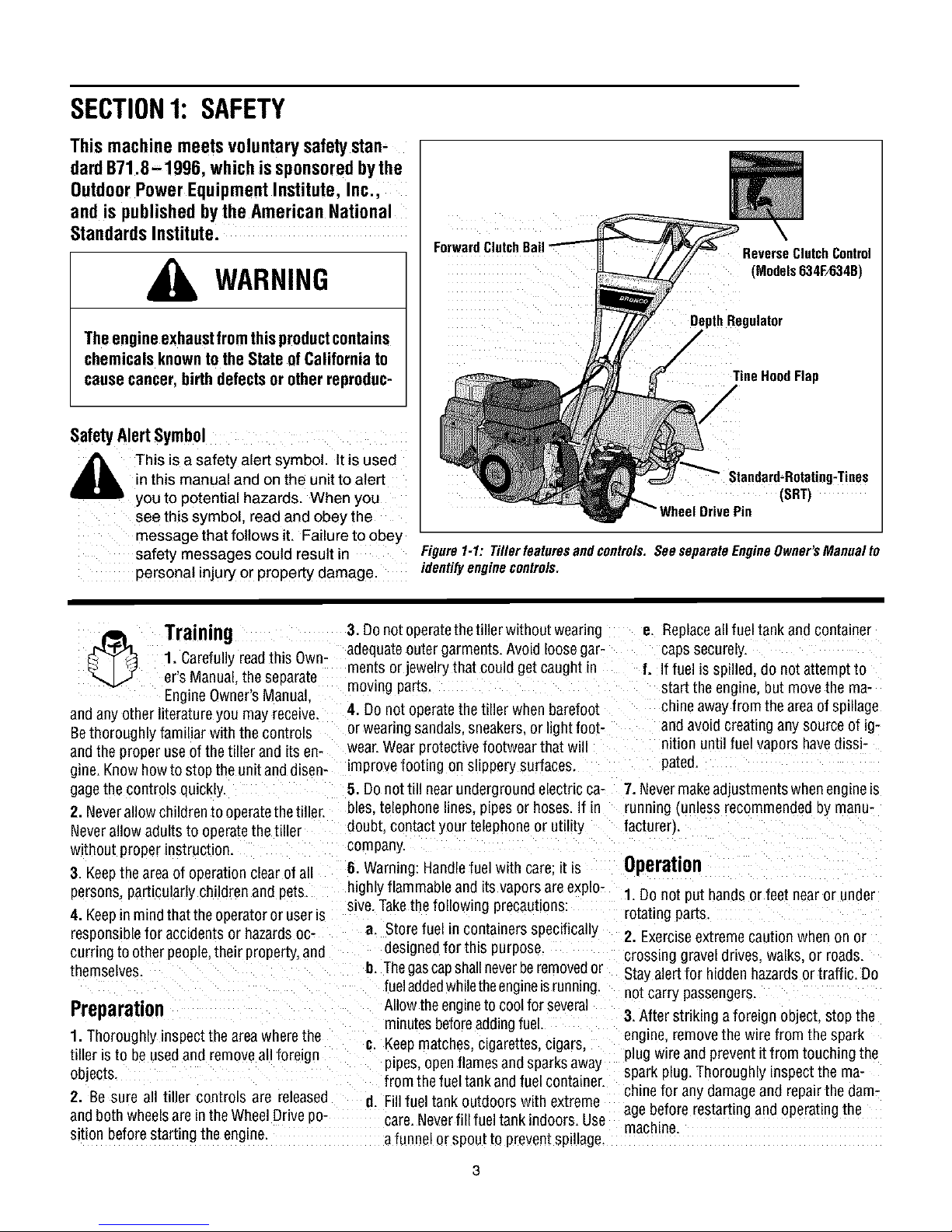
ForwardClutchB_
DepthRegulator
ReverseClutchControl
(Models634F/634B)
TineHoodFlap
/
(SRT)
Figure1-1:Tillerfeaturesandcontrols.SeeseparateEngineOwner'sManualto
identifyenginecontrols.
3. Donot operatethetiller without wearing
1. Carefullyreadthis Own-
Training
er's Manual.the separate
EngineOwner'sManual
andany other literatureyou may receive.
Bethoroughly familiar withthe controls
andthe proper use of the tiller and its en-
gine.Know howto stop the unitand dlsen- improve footing on slippery surfaces.
gagethe controls quickly.
2. Neverallow children to operatethetiller.
Neverallow adults to operatethe tiller
without proper instruction.
3. Keepthe area of operation clear of all
persons,particularly children and pets
4. Keepin mindthat theoperatoror useris
responsiblefor accidents or hazardsoc-
curring to other people,their property,and
themselves.
Preparation
1.Thoroughly inspectthe areawherethe
tiller isto be usedand removeall foreign
objects.
2. Be sure all tiller controls are released
andboth wheelsare in theWheelDrive po-
sition beforestarting the engine.
adequateouter garments. Avoid loosegar-
ments or jewelry that could get caught in
moving parts.
4. Do not operatethe tiller when barefoot
or wearing sandals,sneakers,or light foot-
wear.Wearprotective footwear that wi
5. Donottill near underground electricca- 7. Nevermakeadjustments when engine_s
bles. telephone lines, pipes or hoses.If in running {unlessrecommended oy manu-
doubt contact your telephoneor utility facturer).
company.
6. Warning: Handlefuel with care: it is Operation
highly flammableand its vaporsare explo-
sive.Takethe following precautions:
a. Storefuel in containersspecifically
desLgnedfor this 3urpose.
I]. Thegascapshallneverberemovedor
fueladdedwhiletheengineis running.
Allow theengineto coolfor several
m_nutesbeforeaddingfuel.
#. Keepmatches, cigarettes, cigars,
ptpes,openflames and sparksaway
from the fueltank and fuel container.
d. Fillfuel tank outdoors with extreme
care.Neverfill fueltank indoors. Use
a funnel orspou[ to preventspillage.
e. Replaceall fuel tank and container
caps securely.
f. If fuel is spilled, do not attempt to
start the engine, but movethe ma-
chine awayfrom the areaof sp_llage
and avoid creating any source of ig-
lit{on until fuel vapors havedissi-
pated.
1. Do not put hands or feet near or under
rotating parts
2. Exerciseextremecaution when on or
crossing gravel drives, walks, or roads.
Stayalertfor hidden hazardsor traffic. Do
not carry passengers.
3.Nter striking a foreign object, stop the
engine,removethe wire from the spark
plug wire andpreventitfrom touching the
spark plug. Thoroughly inspectthe ma-
chinefor any damageand repairthe dam-
agebefore restarting andoperatingthe
machine.
Page 4
4. Exercisecautionto avoid slippingor fall- If indoubtaboutthetilling conditions,al- 24. Donot touch engine parts which may
ing.
5. If the unit should start to vibrate aonor-
really,stop the engine,disconnect the
spark plug wire and prevent itfrom touch-
ing the sparkplug,and checkimmediately
for the cause. Vibration is generally a
warning of trouble.
6. Stopthe eng he.disconnectthe spark
plugwire and prevent itfrom touching the
spark plug, whenever you leavethe oper-
atingposition, beforeuncloggingthetines.
or whenmaking any repairs, adjustments
or inspections.
7. Takeall possible precautionswhen leav-
ing the machineunattended. Stop the en-
gine. Disconnectthe spark plug wire and
move it awayfrom thespark plug. Besure
that both wheelsare inthe Wheel Drive po-
sition.
8. Beforecleaning, repairing, or inspect-
ing, stop the engine and makecertain all
mowng parts havestopped. Disconnect
thespark plugwire and prevent itfrom
touching the spark plug to preventacci-
dentalstarting.
9. Theflapon thetine hood must bedown
when operatingthetiller.
tO. Neverusethetiller unless proper
guards, plates, or other safety protective
devicesare in place.
11. Donot run the engineman enclosed
area. Engineexhaust contains careen
monoxide gas. a deadlypoison that is
odorless, colorless, and tasteless.
12. Keepchildren andpetsaway.
13.Neveroperatethetiller underengine wheeldown slopes.
powerif the wheels are in theFreewheel
position.Inthe Freewheelposition, the
wheelswill not holdthe tiller backand the
revolving Linescould propelthetiller rapid-
ly,possibly causingloss of control. Always
engagethe wheels with the wheeldrive
pins in the Wheel Drive position before
starting the engineor engagingthe
tines/wheelswith the Forward ClutchBail
(all models_orthe ReverseClutchcontrol
(Models 634F/634Bonly}.
14. Be aware that the tiller may unex-
pectedlybounceupwardorjumpforward
if the tines shouldstrikeextremelyhard
packedsoil, frozenground,or buriedob-
stacleslike large stones, roots,or
stumps.
waysusethe followingoperatingprecau- behot from operation. Letparts cool down
tionsto assistyou inmaintainingcontrol sufficiently.
ofthe tiller: 25. Pleaseremember:Youcanalwaysstop
a. Walk behindandto oneside of the thetines andwheels by releasingthe For-
tiller, usingonehandonthe handle ward Clutch Bailor on Models 634Fand
barsRelax your arm, but usea 634B the ReverseClutchcontrol. _which-
securehandgrip.
b. Useshallower depthregulator
settings,workinggraduallydeeper
with each pass.
c. Useslowerenginespeeds.
d. Clearthe tilling area of all large
stones,rootsorotherdebris.
e. Avoidusingdownwardpressureon
thehandlebars.If needbe, use
slightupwardpressureto keep the
tines from diggingtoodeeply.
f. Beforecontactinghardpackedsoil
at the end of a row.reduceengine
speedandlift the handlebarsto
raise the tines outof the soil.
g. Inanemergency,stopthetinesand
wheels byreleasingwhichever
clutchcontrolis engaged.Do not
attemptto restrainthetiller.
15. Donot overloadthe tiller's capacityDy
attempting to till too deeplyattoo fast a
rate
16. Neveroperatethe tiller at high trans-
port speeds on hard or slippery surfaces.
Look behindand usecarewhen backing
up
17. Do not operatethetiller ona slopethai
is too steepfor safety.When onslopes,
slow down and makesure you havegood
footing. Never permit the tiller to free-
18. Neverallow bystandersnearthe umt.
19. Onlyuseattachments andaccessories
that areapprovedby the manufacturero1
the tiller.
20. Usetiller attachmentsand accessories
when recommended.
21. Neveroperatethe tiller without good
wsibility orlight.
22. Neveroperatethe tiller if you aretired:
or underthe influence ofalcohol, drugs or
medication.
23. Operatorsshall not tamper with the en-
gine-governor settings onthe machine:
the governor controls the maximum safe
operatingspeedto protectthe engine and
all movingparts from damagecaused by
overspeed. Authorized serviceshall be
sought if a problem exists.
evercontrol isengaged),or by movingthe
_gnitionswitch and/orthrottle control lever
on the engineto "OFF"or "STOP".
26. To load or unloadthe tiller, seethe in-
structions in Section4 of this Manual.
27. Useextreme caution when reversing
or pullingthe machinetowards you.
28. Start the enginecarefullyaccording to
instructionsand with feet well awayfrom
thetines.
29. Neverpickupor carry amachinewhile
theengine is running.
MaintenanceandStorage
1. Keepthe tiller, attachmentsand acces-
sories insafeworking condition.
2. Checkall nuts bolts, andscrews at
ervalsfor proper t_ghtnessto be surethe
equipment is insafeworking condition.
3. Neverstore thetiller with fuel inthefuel
tank insidea building where ignition sourc-
esare presentsuchashotwater andspace
heaters,furnaces, clothesdryers, stoves,
electric motors, etc.L Allow the engineto
cool neforestoring the unit inan'yenclo-
sure.
4. To reducethe chancesof afire hazard.
keepthe enginefree ofgrass, leaves,or ex-
cessivegrease.
5. Storegasolinein a cool. well-ventilated
area,safelyaway from any spark- or
flame-producing equLpment. Store gaso-
line in an approvedcontainer,safelyaway
from the reachof children.
6. Refedto the Maintenancesections of
this Manualand the separateEngineOwn-
er'sManualfor instructions if the unit isto
be stored for an extendedperiod.
7. Neverperform maintenancewhilethe
engineis runmng orthe spark plug wire is
connected,exceptwhen specificahy in-
structed to doso.
8. Ifthefueltankhastobedrained dothis
outdoors.
Page 5
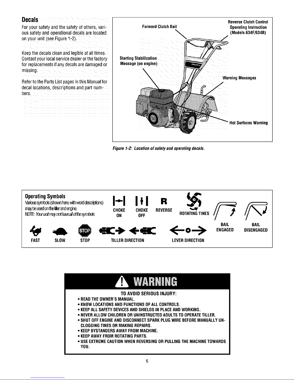
Decals
Foryour safety and the safetyof others, vari-
ous safetyand operationaldecalsare located
on your unit (seeFigure1-2)t
Keepthe decalsclean and legibleat alltimes.
Contactyour localservicedealerorthefactory
for replacementsif any decalsare damagedor
missing.
Referto the PartsList pagesinthis Manualfor
decallocations, descriptions and part num-
bers.
ForwardClutchBail
StartingStabilization
Message(onengine)
Figure1-2:Locationofsafetyandoperatingdecals.
ReverseClutchControl
OperatingInstruction
(Models634F/634B)
WarningMessages
HotSurfacesWarning
OperatingSymbols
w_s _bo_ (shownr_re,_ _crd_)
maybeusedonthellera_lmgine.
NOTEYour_mayr_thavealiof_s_.
FAST SLOW
STOP TILLERDIRECTION LEVERDIRECTION
• READTHEOWNER'SMANUAL.
• KNOWLOCATIONSAND FUNCTIONSOFALLCONTROLS.
• KEEPALLSAFETYDEVICESANDSHIELDSIN PLACEAND WORKING.
• NEVERALLOWCHILDRENORUNINSTRUCTEDADULTSTOOPERATETILLER.
• SHUTOFFENGINEANDDISCONNECTSPARKPLUGWIREBEFOREMANUALLYUN"
CLOGGINGTINESORMAKINGREPAIRS.
• KEEPBYSTANDERSAWAYFROMMACHINE.
• KEEPAWAYFROMROTATINGPARTS.
• USEEXTREMECAUTIONWHEN REVERSINGOR PULLINGTHEMACHINETOWARDS
YOU.
I-'-I Itl R
CHOKE CHOKE REVERSE
ON OFF ROTATINGTINES
<--o-->
TO AVOID SERIOUS INJURY:
BAIL BAIL
ENGAGED DISENGAGED
Page 6
SECTION2: ASSEMBLY
WARNING: To prevent
personalinjury or property
damage,do notstart the engine
until all assemblysteps are
completeandyou have read
and understandthe safetyand
operatinginstructions in this
manual.
INTRODUCTION
Carefullyfollow these assemblysteps to
correctly prepareyour tiller for use. It is
recommendedthat you readthis Section
in itsentirety before beginning assembly.
NOTE: Various tiller models are
presented in this Manual Use only the Checkthat you havethe items listedin the
information appropriate for your tiller LooseParts List (contactyour localdealer
model Engine styles varyby model Your or the factory itemsare missing or dam-
engine may appear differently than those aged).
illustratedin thismanual.
INSPECTUNIT
Inspectthe unitand carton for damageLm-
mediatelyafter delivery. Contactthe cam-
er (trucking company) if you find or
suspectdamage. Inform them of the dam-
ageand request instructions for filing a 1
claim. Toprotect your rights, put your
claim inwriting andma_la copyto the car- 1
rier within 15 days after the unit has been 1
delive'ed. Contact Troy-Bilt LLCil you 6
needassistancein this matter. 2
TOOLSMATERIALSNEEDED
Ill 3,8" open-endwrench* 6 Hex nut. 5/16"-18 Iockwashers(.H)and5/16"-18 hexnuts (I).
(.2) 7/16' open-end wrench" 1 Hexnut #10-24 NOTE: If a support bracketwill not move
12_ 1/2" open-endwrench* 2 HexIocknut.3,8"-16 loosenattaching screw (J) and nut.
(2) 946"open-end wrench* 1 Spring, cable(see W, Fig.2-5_ 3. Attach the handlebarassembly (.K_to
(1) Largead Jstablewrench (.seeP, Fig.2-4_ 16"-18x 1-1/2" screws (.G_,5/16" split
_Models634F/634Bonly} 2 Lockwasher 3/8
(.1J Scissors to trim plasticties/
(1) Ruler (for belttension check_
111 Blockof wood (to support tiller when
remowng wheels)
111 Tire pressure gauge(for modelswith
pneumatictires_
Ill Cleanoil funnel
111 Motoroil Refertothe Engine0wner's
Manualfor oilspecificationsand
quantityrequired.
* Adjustablewrenches mayDeused,
ASSEMBLYSTEPS
STEP 1: UNPACKING INSTRUCTIONS
NOTE:While unpacking, do not severely
bendany control cables.
1.Thetiller weighsapproximately133 lbs.
Donot attempt to remove it from the ship-
ping platform until instructed to do so m
these Assembly steps.
2. Removeanypackagingmaterialfrom
the carton. Removeany staplesfrom the
bottom ofthe carton and removethe car-
ton from the shipping platform.
3. Removeall unassembledpartsand the
separatehardwarebagfrom the carton.
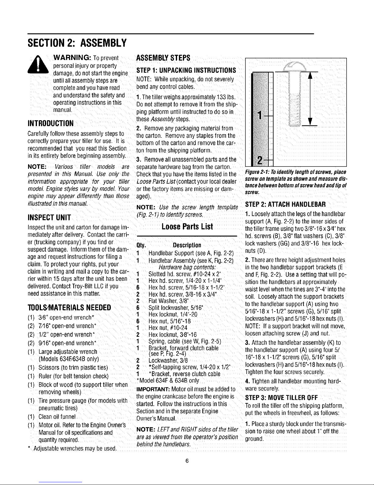
NOTE: Use the screw length template
(Fig.2-1) toidentify screws
LoosePartsList
Qty. Description
1
HandlebarSupport (seeA, Fig. 2-2_
HandlebarAssembly(seeK,Fig.2-2)
Hardwarebag contents:
Slotted hd. screw #10-24 x 2'
Hex hd. screw 1/4-20 x 1-1 '4
Hex hd. screw 5/16-18 x 1-1 2"
Hex hd. screw. 3/8-16 x 3/4
2
FlatWasher.3/8
6 Split Iockwashe_5/16"
1 HexIocknut. 1/4"-20 5Pi6"-18x 1-1/2" screws (G).5/16" split
1 Bracket.forward clutchcable the handlebarsupport (A) usingfour 5.
2
*Self-tappingscrew.1/4-20 x 1/2" IockwashersIHI and5/16"-18 hexnuts (I).
1 *Bracket reverseclutch cable
*Model 634F& 634B only
IMPORTANT:Motor oil must beaddedto
the enginecrankcase beforetheengine is
started. Followthe instructions inthis
Sectionand in the separateEngine
Owner'sManual.
NOTE: LEFTandRIGHTsidesofthetiller sion to raise one wheelabout l" off the
are as viewedfrom the operator's position ground.
behind the handlebars.
Figure2-1: Toidentifylengthofscrews,place
screwontemplateasshownandmeasuredis-
tancebetweenbottomofscrewheadandtipof
scrBw,
STEP 2: ATTACH HANDLEBAR
1. Looselyattach the legsof the handlebar
support (A, Fig.2-2) to the innersides of
thetiller frame usingtwo 3/8"-16x 3/4"hex
hd. screws (B), 3/8"flat washers(C), 3/8"
lock washers (GG_,and 3/8"-16 hexlock-
nuts (D_,
2. Therearethree height adjustment holes
in the two handlebarsupport brackets (.E
and E Fig. 2-2). Usea setting that will po-
sition the handlebarsat approximately
waist levelwhenthetines are3"-4"intothe
so_l. Looselyattachthe support brackets
to the handlebarsupport (.A_using two
Tightenthe four screwssecurely
4. Tighten all handlebarmounting hard-
waresecurely.
STEP3: MOVE TILLER OFF
Toroll thetiller off the shipping platform.
put the wheels in freewhee asfollows:
1. Placeasturdy block underthe transmis-
m
Page 7
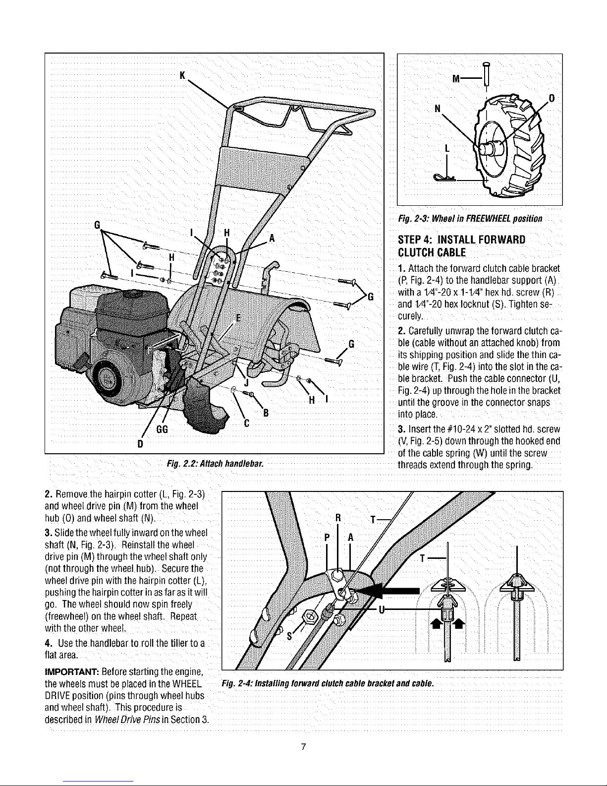
Fig.2,2:AHachhandlebar, threads extendthrough the spring.
2. Removethe hairpin cotter (L, Fig.2-3)
and wheel drive pin (M) from the wheel
hub (0) and wheel shaft (N).
3. Slidethe wheelfully inwardonthewheel
shaft (N, Fig.2-3). Reinstallthe wheel
drive pin (M) through the wheelshaft only
(not through the wheel hub). Securethe
wheeldrive pin with the hairpin cotter (L),
pushingthe hairpincotter inasfar asit will
go. Thewheel should now spin freely
(freewheel) on the wheel shaft. Repeat
with the other wheel.
4. Usethe handlebarto roll the tiller to a
flat area.
Fig. 2-3: Wheelin FREEWHEELposition
STEP4: INSTALL FORWARD
CLUTCH CABLE
1. Attach the forward clutch cablebracket
(P,Fig.2-4) to the handlebarsupport AI
with a1/4"-20x 1-1/42hexhd. screw (R)
and V4"-20 hexIocknut (S). Tightense-
curely.
2. Carefullyunwrapthe forward clutch ca-
ble (cable without anattachedknob, from
its shipping position and slidethe thin ca-
ble wire (T.Fig.2-4 intothe slot in the ca-
ble bracket. Pushthe cable connector (U.
Fig.2-4) upthrough the holein the bracket
until the groove inthe connector snaps
into place.
3. Insertthe #10-24 x 2"slotted hd.screw
(V,Fig.2-5) downthrough the hookedend
of the cable spring (W) until the screw
IMPORTANT:Beforestarting theengine,
thewheels must beplacedin the WHEEL Fig.2=4:Installingforwardclutchcablebracketandcable.
DRIVEposition (pins through wheelhubs
andwheelshaft). This procedureis
described in WheelDrivePinsin Section3.
Page 8
4. Threadthe #10-24 hexnut (Z,Fig. 2-5)
halfwayonto the screw (V).
5. Threadthe screw IV_into thecable ad-
juster (X).
6. Hookthe cable spring (W,Fig.2-6) into
theV-shaoedbend in the ForwardClutch
Bail _Y).
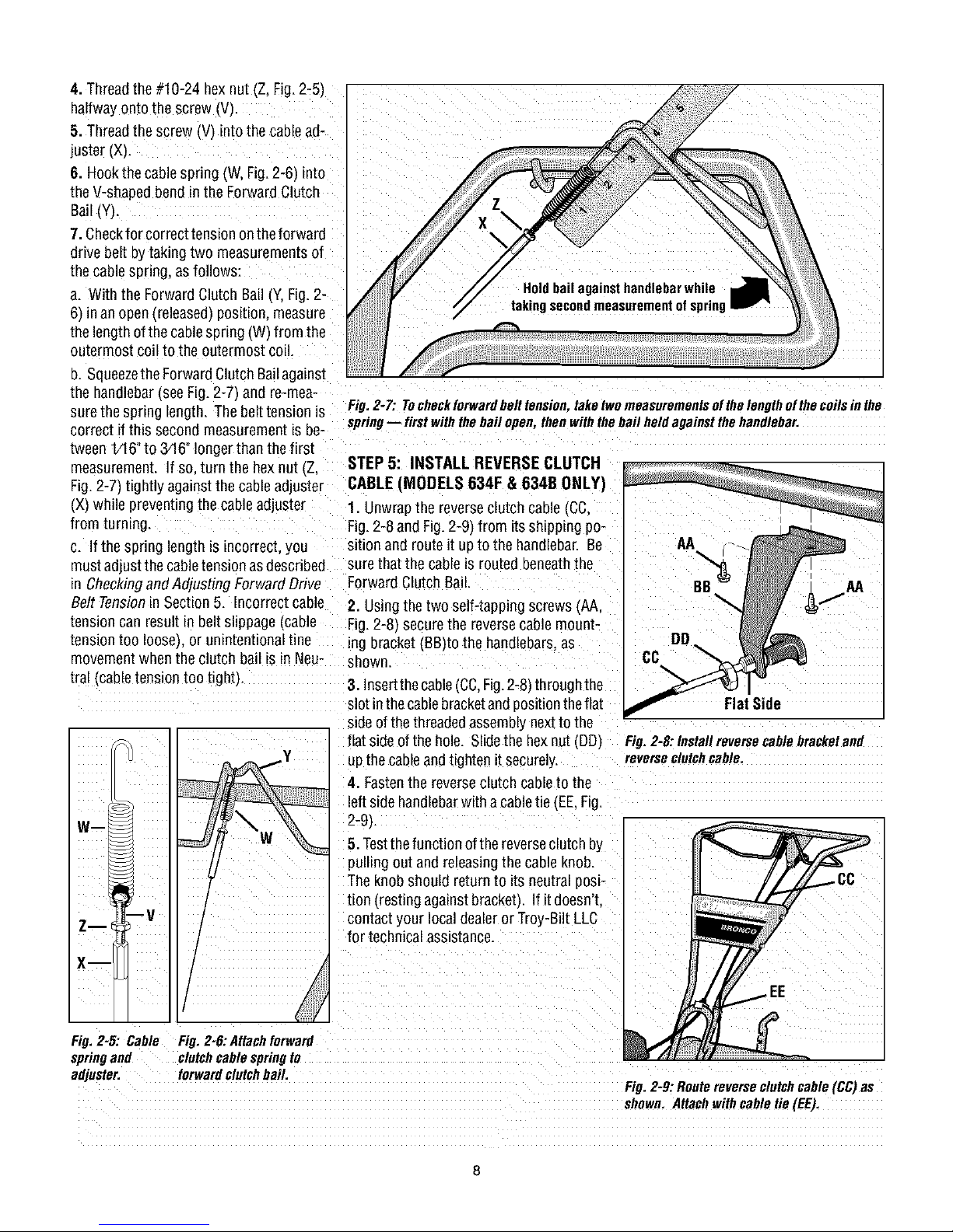
7. Checkfor correcttension ontheforward
drive belt by taking two measurementsof
thecablespnng, asfollows:
a. With the ForwardClutch Bail(Y,Fig.2-
6/in an open(released)position, measure
thelength ofthecablespring (W from the
outermost coil to the outermost coil.
n. Squeezethe ForwardClutchBailagainst
the handlebar(see Fig. 2-7_and re-mea-
surethe spring length, Thebelt tensionis
correct if this second measurementis be-
Fig.2-7: Tocheckforwardbelttension,taketwomeasurementsofthelengthofthecoilsinthe
spring-- firstwiththebailopen,thenwiththebailheldagainstthehandlebar.
tween 1/16"to 3/16"longer than thefirst
measurement. If so. turn the hexnut (Z.
Fig.2-7) tightly against the cableadjuster
(X_while preventingthe cableadjuster
from turnmg.
c. Ifthe spring length is incorrect, you
mustadjust the cabletension asdescribed
STEP 5: INSTALL REVERSECLUTCH
CABLE (MODELS 634F & 634B ONLY)
1. Unwrapthe reverseclutch cable(CC.
Fig.2-8 and Fig.2-9_from itsshipping po-
sition and route it upto the handlebar. Be
surethat the cableis routed beneaththe
in Checkingand Adjustin_ ForwardDrive Forward Clutch Bail.
Belt Tensionin Section 5. Incorrectcable
tension can result in belt slippage Icable
tension too IooseLor unintentional tine
movement when the clutch bail is in Neu-
tral Icable tension too tight}
2. Usingthe two self-tapping screws (AA,
Fig.2-8) securethe reversecable mount-
ing bracket(BB)to the handlebars,as
show_
3. Insertthe cable(CC,Fig.2-8) through the
slot inthecablebracketandpositiontheflat
sideofthe threadedassemblynextto the
flat sideof the hole. Slidethe hex nut (DD/
up the cable andtighten it securely
4. Fastenthe reverseclutch cable to the
left side handlebarwith a cabletie (EE,Fig.
Wm
2-9L
5. Testthefunction ofthe reverseclutch by
pulling out and releasing the cableknob.
Theknob should return to its neutral posi-
tion (resting against bracketL Ifit doesn't.
Zm
contact your localdealer or Troy-Bilt LLC
for technical assistance.
X--
CC
Flat Side
Fig. 2-8: Install reverse cable bracketand
reverseclutch cable,
Fig, 2-5: Cable
springand
adjuster.
Fig. 2-6: Attachforward
clutch cable spring to
forwardclutchbail.
Fig.2-9:Routereverseclutchcable(CC)as
shown.Attachwithcabletie(EL:).
Page 9
31bY I_: L;I'IEL;KLEVEL UI-
Thetransmission wasfilled with gearoil at
thefactory.However,youshouldcheckthe
gearoil levelatthis timeto makecertain it
is correct.
IMPORTANT:Donot operatethe tiller if the
gearoil levelis low. Doingso will result in
severedamageto thetransmission com-
ponents.
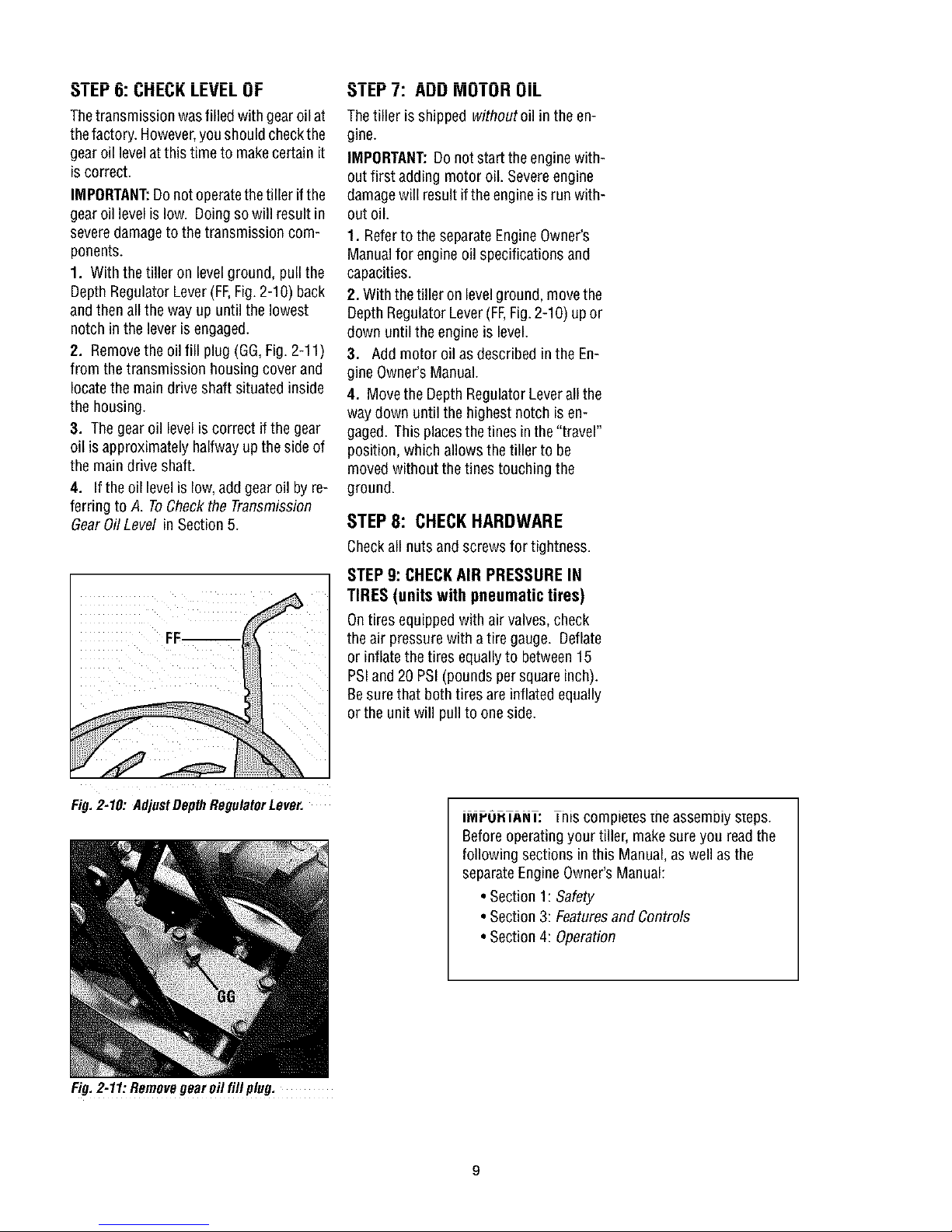
1. With the tiller on levelground, pull the
Depth RegulatorLever(FF,Fig.2-10) back
andthen all the way up until the lowest
notch inthe lever isengaged.
2. Removethe oil fill plug (GG,Fig.2-11)
from the transmission housingcover and
locatethe main drive shaft situated inside
the housing.
3. Thegear oil level is correct ifthe gear
oil isapproximately halfwayup theside of
the maindrive shaft.
4. If the oil levelis low,add gear oil byre-
ferring to A. ToCheckthe Transmission
GearOil Level inSection 5.
_IbY I: AUU MUIUH UIL
Thetiller isshipped withoutoil in theen-
gine.
IMPORTANT:Do not start theengine with-
outfirst adding motor oil. Severeengine
damagewill resultifthe engineis run with-
out oil.
1. Referto the separateEngineOwner's
Manualfor engine oil specifications and
capacities.
2. With thetiller on levelground, movethe
Depth RegulatorLever(FF,Fig.2-10) upor
down until the engineis level.
3. Add motor oil asdescribed in the En-
gine Owner'sManual.
4. Movethe DepthRegulatorLeverall the
way down until the highest notch is en-
gaged. This placesthetines in the "travel"
position, which allows the tiller to be
moved without thetines touching the
ground.
STEP8: CHECKHARDWARE
Checkall nuts and screws for tightness.
STEP 9: CHECKAIR PRESSURE IN
TIRES (units with pneumatic tires)
Ontires equipped with air valves, check
theair pressurewith atire gauge. Deflate
or inflatethe tires equallyto between15
PSIand20 PSI(pounds per squareinch).
Besure that both tires are inflated equally
orthe unit will pullto one side.
Fig. 2-10: AdjustDepth RegulatorLever.
Fig.2-11:Removegearoil fill plug,
IMrU. lANl: his compie[esme assemoiy steps.
Beforeoperatingyour tiller, makesure you readthe
following sections in this Manual,as well as the
separateEngineOwner'sManual:
• Section1: Safety
• Section3: Featuresand Controls
• Section4: Operation
Page 10
SECTION3: FEATURESANDCONTROLS
WARNING: Before
operatingyour machine,
carefully readand understand
all safety, controls and
operatinginstructions in this
Manual,the separateEngine
Owner's Manual,and on the
decalson the machine.
Failureto follow these
instructions canresult in
serious personal injury.
INTRODUCTION
This Section describesthe location and
function of the controls onyour tiller. Re-
ferto thefollowing Section,Operationfor
detailedoperating instructions.
Practiceusing these controls, with the en-
gine shut off, until you understandthe op-
eration ofthe controls andfeelconfident
with eachof them.
Forward
Reverse ClutchControl
(Models634F/634B)
DepthRegulator
Handlebar HeightAdjustment
Wheel Drive Pin
(oneachwheel)
ENGINE CONTROLS
Referto the engine manufacturer's Engine
Owner'sManual (included inthe tiller liter-
ature package)to identify the controls on
your engine.
IMPORTANT:Thecontrol for stopping the
engine is locatedon the engine.
WHEEL DRIVE PINS
Eachwheel is equippedwith awheeldrive
pin (A, Figures3-2 and 3-3) that secures
thewheelto the wheel shaft (B). The
wheelscan be positioned ineither a
WHEELDRIVEora FREEWHEELmode.
WARNING: Neverallow
eitherof thewheelsto bein the
FREEWHEELposition whenthe
engineis running. Alwaysput
both wheelsin theWHEEL
DRIVEposition beforestarting
theengine.
Failureto comply could cause
loss of tiller control, property
damage,or personalinjury.
Beforestarting theengine,put both wheels
in the WHEELDRIVEposition byinserting
thewheel drive pins through the wheel
hubsand the wheel shaft. Doingso
"locks" the wheels to the wheel shaft,
causingthe wheelsto turn wheneitherthe
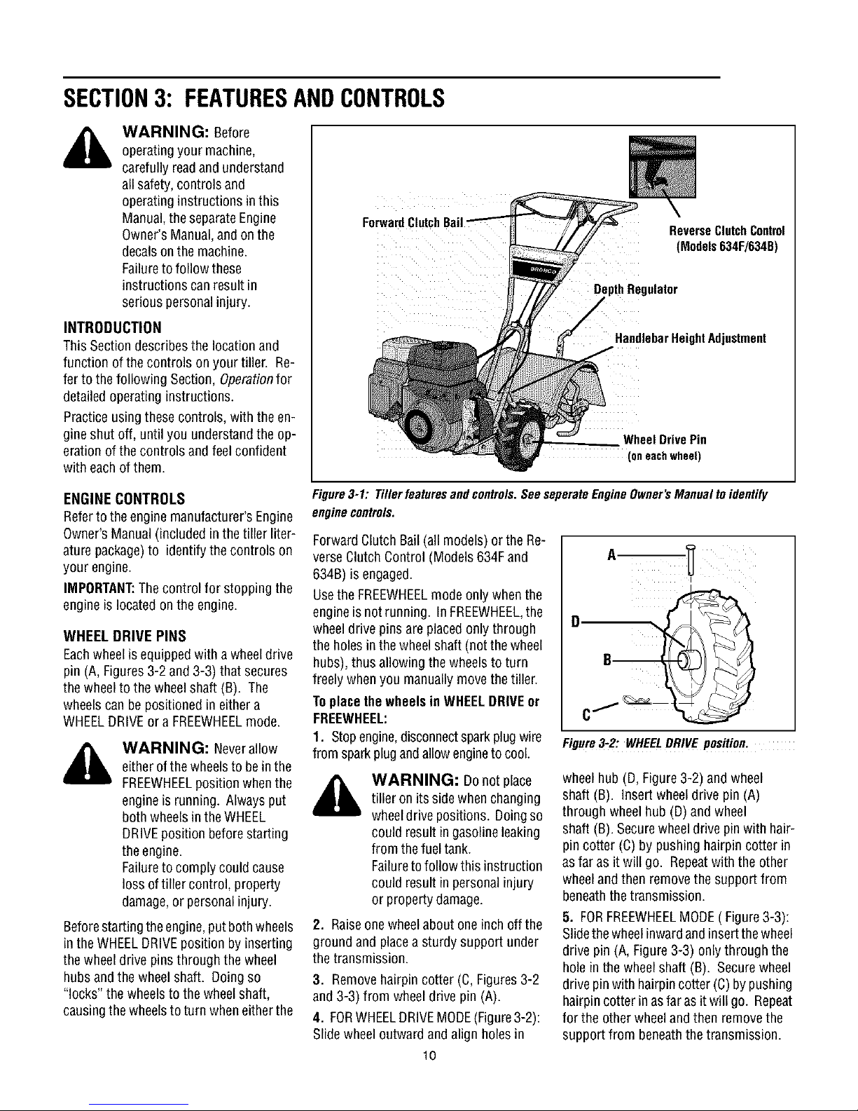
Figure3-1: Tillerfeaturesandcontrols.SeeseperateEngineOwner'sManualtoidentify
enginecontrols.
Forward Clutch Bail (all models) or the Re-
verseClutch Control (Models 634Fand
634B) is engaged.
Usethe FREEWHEELmode only whenthe
engineis not running. In FREEWHEEL,the
wheeldrive pins are placed only through
theholes in thewheelshaft (not the wheel
hubs), thus allowing the wheelsto turn
freely whenyou manuallymovethe tiller.
Toplacethe wheels in WHEELDRIVEot
FREEWHEEL:
1. Stopengine,disconnectsparkplugwire
from sparkplug andallowengineto cool.
WARNING: Donot place
tiller on its side when changing
wheeldrive positions. Doing so
could result in gasoline leaking
from thefuel tank.
Failureto follow this instruction
could result in personal injury
or propertydamage.
2. Raiseonewheelabout one inch off the
ground and placea sturdy support under
thetransmission.
3. Removehairpin cotter (C, Figures3-2
and 3-3) from wheel drive pin (A).
4. FORWHEELDRIVEMODE(Figure3-2):
Slide wheel outward and align holes in
10
Figure3-2: WHEELDRIVE position.
wheelhub (D,Figure3-2) and wheel
shaft (B). Insert wheeldrive pin (A)
through wheel hub (D)and wheel
shaft (B). Securewheeldrive pinwith hair-
pin cotter (C) by pushing hairpincotter in
asfar as it will go. Repeatwith the other
wheeland then removethesupport from
beneaththe transmission.
5. FORFREEWHEELMODE( Figure3-3):
Slidethe wheelinwardand insertthewheel
drive pin (A, Figure3-3) onlythrough the
hole in the wheel shaft (B). Secure wheel
drive pinwith hairpincotter (C)by pushing
hairpin cotter inasfaras it will go. Repeat
for the other wheeland then removethe
support from beneaththe transmission.
Page 11
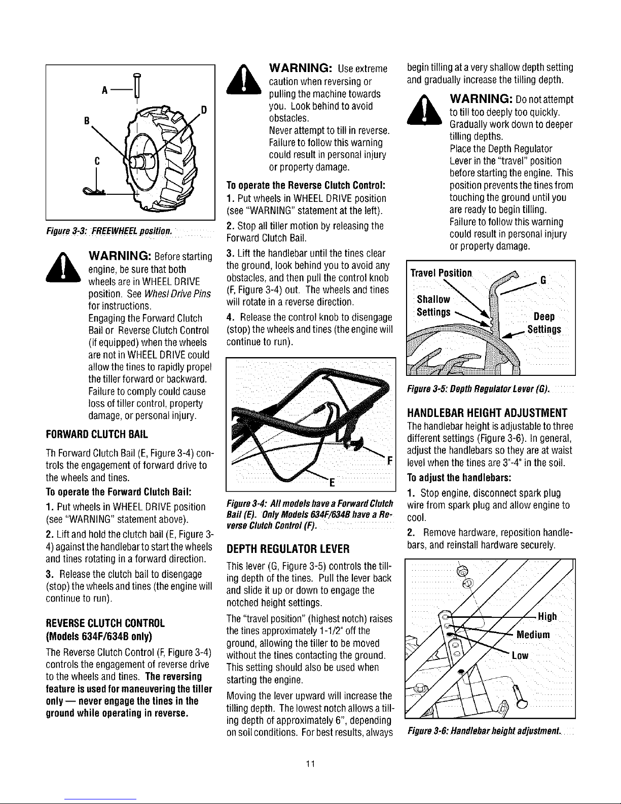
Figure3-3: FREEWHEELposition.
,_ WARNING: Useextreme
caution when reversing or
pulling the machinetowards
you. Look behindto avoid
obstacles.
Neverattempt totill inreverse.
Failureto follow this warning
could result in personal injury
or propertydamage.
Tooperatethe ReverseClutchControl:
1. Putwheels in WHEELDRIVEposition
(see"WARNING"statementat the left).
2. Stopall tiller motion by releasingthe
Forward Clutch Bail.
begintilling at avery shallow depthsetting
and gradually increasethe tilling depth.
WARNING: Donotattempt
totill too deeply too quickly.
Graduallywork downto deeper
tilling depths.
Placethe DepthRegulator
Leverin the "travel" position
beforestartingthe engine. This
position preventsthetines from
touching the grounduntil you
arereadyto begintilling.
Failureto follow this warning
could result in personalinjury
or property damage.
_, WARNING: Beforestarting 3. Lift the handlebaruntil the tines clear
engine,besurethat both theground, look behindyou to avoid any
wheelsare in WHEELDRIVE obstacles,and then pullthe control knob
position. SeeWheslDrivePins (F,Figure3-4) out. The wheelsand tines
for instructions, will rotate in a reversedirection.
Engagingthe ForwardClutch 4. Releasethe control knob to disengage
Bail or ReverseClutchControl (stop)the wheelsand tines (the enginewill
(if equipped) whenthewheels continue to run).
arenot in WHEELDRIVEcould
allowthe tines to rapidly propel
thetiller forward or backward.
Failureto comply could cause
loss of tiller control, property
damage,or personalinjury.
FORWARDCLUTCHBAIL
ThForwardClutch Bail(E,Figure3-4) con-
trols the engagementofforward drive to
thewheelsand tines.
Tooperatethe ForwardClutchBail:
1. Put wheelsin WHEELDRIVEposition Figure3-4:AIImodelshaveaForwardClutch
(see"WARNING"statementabove). Bail (E). OnlyModels634F/g34Bhavea Re,
verseClutchControl(F).
2. Lift and hold theclutch bail (E, Figure 3-
4)againstthehandlebartostartthewheels DEPTH REGULATOR LEVER
andtines rotating ina forward direction.
This lever (G,Figure3-5) controls the till-
3. Releasethe clutch bail to disengage ing depth of the tines. Pull the leverback
(stop) the wheelsandtines (theenginewill and slide it up ordown to engagethe
continue to run). notched height settings.
Figure3-5:DepthRegulatorLever(GJ.
HANDLEBAR HEIGHT ADJUSTMENT
Thehandlebar heightisadjustableto three
different settings (Figure3-6). In general,
adjust the handlebarsso they areat waist
levelwhenthe tines are 3"-4" in the soil.
Toadjustthe handlebars:
1. Stop engine, disconnect spark plug
wire from spark plugand allow engine to
cool.
2. Remove hardware,reposition handle-
bars, and reinstall hardwaresecurely.
REVERSECLUTCHCONTROL The"travel position"(highest notch) raises
(Models 634F/634B only) thetines approximately1-1/2"off the
TheReverseClutch Control (F,Figure3-4) without the tines contacting the ground.
controls the engagementof reverse drive This setting should also be usedwhen
to the wheelsand tines. Thereversing starting the engine.
featureis usedfor maneuveringthe tiller
only-- neverengage the tines in the Moving the leverupward will increasethe
groundwhile operatingin reverse, tilling depth. Thelowest notch allowsa till-
ground,allowing the tiller to be moved
ing depth of approximately 6", depending
on soil conditions. Forbestresults,always
11
Figure3-6:Handlebarheightadjustment.
Page 12

SECTION4: OPERATION
WARNING: Before ReverseClutchControl
operatingyour machine, (Models634F/634B)
carefully readand understand
all safety (Section 1),controls
(Section 3) and operating
instructions (Section 4) inthis
Manual,the separateEngine
Owner's Manual,and on the Clutch Bail
decalson the machine.
Failureto follow these
instructions canresult in
serious personal injury.
INTRODUCTION
Readthis OperationSection and the sepa-
rate EngineOwner's Manualbeforeyou
start the engine. Then,takethe time to fa-
miliarize yourself with the basicoperation
of thetiller before using it in the garden.
Findan open,levelareaand practiceusing
thetiller controls without thetines engag-
ing the soil (put tines in "travel" setting).
Onlyafter you've becomecompletely fa-
miliar with thetiller shouldyou begin using
it in the garden.
BREAK-IN OPERATION
Perform the following maintenanceafter
thefirst two (2) hours of new operation
(seeMaintenanceSection in this manual
and in the EngineOwner'sManual).
1. Changeengine oil.
2. Checkfor looseor missing hardwareon
unit. Tightenor replaceas needed.
3. Checktension onforward drive belt.
4. Checktransmission gear oil level.
STARTINGANDSTOPPING
Pre-StartChecklist
With the sparkplug wire disconnected
from the sparkplug,perform thefollowing
checksand services beforeeach use:
1. Readthe Safetyand ControlsSections
in this manual. Readthe separateEngine
Owner'sManual providedwith the unit.
2. Putthewheels intheWHEELDRIVE
position (wheel pins must bethrough
holes in wheel hubs and wheel shaft).
3. Checkunit for loose or missing hard-
ware. Serviceas required.
4. Checkengine oil level. See Engine
Owner'sManual.
Pin
Fig, 4-1
5. Checkthatall safetyguardsand covers
are in place.
6. Checkair cleanerand enginecooling
system. SeeEngineOwner'sManual.
WARNING: GASOLINEIS
HIGHLYFLAMMABLEAND ITS
VAPORSAREEXPLOSIVE.
Follow gasolinesafety rules in
this Manual(see Section1) and
in the separateEngineOwner's
Manual.
Failureto follow gasolinesafety
instructions can result in
serious personal injury and
property damage.
7. Fillthefueltank with gasolineaccording
to the directions in theseparate Engine
Owner'sManual. Followall instructions
and safety rules carefully.
8. Attach spark plug wireto spark plug.
StartingtheEngine
Thefollowing steps describe how to start
and stop the engine.
WARNING: Donotattempt
to engagethetines or wheels
until you havereadall ofthe
operatinginstructions in this
Section. Also, reviewthesafety
rules in Section 1: Safety,and
the tiller and enginecontrols
information in Section3:
FeaturesandControls.
1. Completethe Pre-Start Checklist on
this page.
2. Putthe wheels inthe WHEELDRIVEpo-
sition (seeWheeIDrivePinsinSection 3 of
this manual).
,_ WARNING: To help
• Beforestartingengine, potbothwheels
in the WHEELDRIVE position. Never
have wheels in FREEWHEELposition
when engine is running. When the
wheels are in FREEWHEEL,they do not
hold backthe tiller and the tines could
propelthe tiller rapidly
ward orbackward.
• Before starting engine, pot Forward
Clutch Bail (all models) and Reverse
ClutchControl(Models 634F/634Bonly)
in neutral(disengaged) positionsby re-
leasing levers.
• Never run engine indoorsor in en-
closed, poorly ventilated areas. Engine
exhaust containscarbon monoxide, an
odorlessand deadlygas.
• Avoidenginemufflerandnearbyareas.
Temperaturesin theseareas mayexceed
150° F.
3. Movethe DepthRegulatorLever all the
way down to the "travel" position, sothat
thetines clearthe ground.
4. Releaseall controls on thetiller.
5. On engine'swith afuel shut-off valve,
turn valve to open position, as instructed
in the separateEngineOwner's Manual.
6. Putignition switch and/or throttle con-
trol leverlocated on engine in the "ON",
"RUN", "FAST"or "START"position, as in-
structed inthe EngineOwner's Manual.
7. Chokeor prime engine,as instructed in
EngineOwner'sManual.
8. Putone hand on fuel tank to stabilize
unit when pulling starter rope handle.
Thenuserecoil starter to start engine,as
instructed inthe EngineOwner's Manual.
Whenenginestarts, graduallymove choke
lever (if so equipped)to "NOCHOKE",
"CHOKEOFF"or "RUN" position.
9. Usethe "FAST"throttle speedsetting
whentilling.
prevent serious personalinjury
or damageto equipment:
12
Page 13

KEEPAWAYF_OMROTATING11NES.
ROTATING11NE$WILLCAUSEINJURY.
Stoppingthe EngineandTiller
1. Tostop the wheelsandtines, releasethe
ForwardClutch Bail(all models)or the Re-
verse Clutch Control (Models 634Fand
634B) -- whichevercontrol isin use.
2. Tostop theengine, putthe ignition
switch and/or thethrottle control leverin
the "OFF"or "STOP"position.
OPERATINGTHETILLER
Thefollowing operating instructionspro-
videguidelines to using your tiller effec-
tively and safely. Besureto read Tilling
Tips& Techniquesin this Section before
actually putting the tines into the soil.
NOTE:Thisis a traditional "Standard-Ro-
tating-Tine" (SRT)tiller with forward ro-
tating tines. It operatescompletely
differently from "Counter-Rotating-Tine"
(CRT)tillers or from front-tine tillers.
1. Followthe Pro-Start Checklist at the
beginning of this Section. Besurethat the
wheelsare in the WHEELDRIVEposition.
2. Movethe DepthRegulatorLeverall the
way down, sothat thetines clearthe
ground. Usethis position whenpracticing
with thetiller andwhen traveling between
tilling sites. Beforeactuallytilling, move
the leverto the desireddepth setting (see
Tilling Tips & Techniques).
3. Start engine and allow itto warm up.
Thenput throttle in "FAST"setting.
4. For forward motion of the wheelsand
tines:
(a) Pull ForwardClutch Bail (Fig. 4-1) up
againsthandlebar. Releasebailto stopfor-
ward motion of wheels and tines.
(b) Whentilling, relaxand letthe wheels
pull the unit while thetines dig. Walk be-
hindand a littleto oneside of the unit. Use
one hand, yet keepa light--but secure--
grip onthe handlebar(while keepingyour
arm loose). SeeFig.4-2. Let the unit
move at its own paceand do not push
down on the handlebarsto try and force
thetines to dig deeper--this takesweight
off the wheels,reduces traction, and caus-
esthe tines to try and propel the tiller.
WARNING: Donot push
down onthe handlebarsto try
to makethe tiller till more
deeply. This preventsthe
wheelsfrom holding the tiller
backand canallow thetines to
rapidly propelthe tiller forward,
which could result in loss of
control, property damage,or
personalinjury.
5. For reversemotion of the wheelsand
tines (Models 634F/634Bonly):
(a) Look behindand exercisecaution when
operating in reverse. Denottill while in
reverse.
(b) Stopall forward motion. Lift handle-
bar with one handuntil tines are off the
ground and then pull ReverseClutchCon-
trol knob out (seeFig.4-3). Tostop revers-
ing, let go of ReverseClutch Control knob.
(b) Swingthe handlebarto the left sothe
right wheeltakesa "step" backward.Next
swing the handlebarto the right so the left
wheel"steps" backward.Repeatasneeded.
(c) If longer distances needto becovered
in reverse,shut off the engine,then place
thetwo wheelsin FREEWHEEL.
7. ToTurnthe Tiller Around:
(a) Practiceturning thetiller in a level,
open area. Bevery carefulto keepyour
feetand legsawayfrom the tines.
(b) Tobeginaturn, liftthe handlebarsuntil
thetinesareoutofthe groundandtheengine
andtines are balancedoverthewheels(Fig.
4-4).
(c) With tiller balanced,push sidewayson
handlebarto steer in direction of turn (Fig.
4-5). After turning, slowly lowertines into
soil to resumetilling.
Fig.4-4: Tobeginturn,lift handlebarsuntil
tinesareoutofgroundandunitisbalanced.
Fig.4-2: Useonehandto guidetiller when handlebaruntil tines areoff theground.
movingforward.
Fig.4-5: Withtinesoutofground,pushhae-
dlebarssidewaystoturntiller.
Fig.4-3: Raisetinesoffgroundandlook StoppingtheTillerandEngine
behindwhenmovinginreverse. 1. Tostop thewheels and tines, release
6. To movethe Model630Cin reversefor
short distances:
(a) Releaseforward ClutchBail. Thenlift
the ForwardClutch Bail (all models) or the
ReverseClutch Control (Models 634Fand
634B) -- whichevercontrol is in use.
2. Tostop theengine, putthe ignition
switch and/orthe throttle control lever in
the "OFF"or "STOP"position.
13
Page 14

TILLING TIPS& TECHNIQUES
TillingDepths
_=i, WARNING: Before
A _• tilling, Contactyour
,m ==== telephoneor utilities
companyand inquireif
underground equipment or
linesare used on your
property.Donottill near
buried electric cables, deeper.(Wateringthe areaafew daysprior to tilling will maketilling easier,aswill lettingthe
telephone lines, pipesor newlyworkedsoil setfora dayortwo beforemakingafinal, deeptilling pass.)
hoses.
• Whencultivating(breakingupsurfacesoilaroundplantsto destroyweeds,seeFig.4-9), adjustthetines to digonly 1"to 2"deep. Using
shallowtilling depthshelpspreventinjuryto plantswhoserootsoftengrow closetothesurface. If needed,lift uponthehandlebarsslightly
to preventthetines from diggingtoo deeply.(Cultivatingona regularbasisnotonlyeliminatesweeds,it also loosensandaeratesthe soil
for bettermoistureabsorptionand fasterplantgrowth.)
• Avoid pushingdownon thehandlebarsinanattemptto forcethe tiller to dig deeper.Doing
sotakesthe weightoff the poweredwheels,causingthemto losetraction.Withoutthewheels
helpingto holdthe tiller back,thetineswill attemptto propelthetiller - often causingthetiller
to skip rapidlyacrossthe ground. (Sometimes,slight downwardpressureonthe handlebars
will helpgetthrougha particularlytough sectionof sodor unbrokenground,butin most cases
this won't benecessarY.)
• Avoid trying to digtoo deeplytoo quickly,especiallywhen bustingsodor when tilling soil
that hasn'tbeentilledfor sometime. Useshallowdepthregulatorsettings(onlyaninch ortwo
deep)forthefirst passesthrough the soil. Witheachsucceedingpass,diganotherinch ortwo
ChoosingCorrectWheel& Tine Speeds With experience,you will find the"just right" tillingdepth andtillingspeedcombination
that is bestfor yourgarden.
Setthe enginethrottle leverataspeedtogivetheengineadequatepowerandyetallow it to operateattheslowestpossiblespeed...atleast
until you haveachievedthe maximumtilling depthyou desire.Fasterenginespeedsmaybedesirablewhenmakingfinal passesthrough
theseedbedor whencultivating.Selectionofthecorrectenginespeed,in relationto thetilling depth,will ensureasufficientpower levelto
dothejobwithout causingtheengineto labor.
Let theTiller Dothe Work
Whiletilling, relaxandletthewheelspullthe
tiller along while the tines do the digging.
Walkonthe sidethat is notyet finished(to
avoidmakingfootprints inthefreshlytilled
soil) and lightly, but securelygrip the han-
dlebarwith justonehand,
AvoidMakingFootprints
Wheneverpossible, walk on the untilled
sideofthe unitto avoidmakingfootprints in
your freshlytilled or cultivatedsoil. Foot-
prints causesoil compactionthat canham-
per root penetration and contributeto soil
erosion. They can also !'plant" unwanted
weed seeds back into the freshly tilled
ground.
PreparingSeedbeds
• When preparinga seedbed,go overthe samepathtwice in the first row,then
overlapone-half the tiller width on therest ofthe passes(seeFig.6). When fin-
ishedin onedirection, makeasecondpassat arightangle,asshown in Fig.4-7.
Overlapeachpassfor bestresults(in very hardground,it maytakethreeor four
passesto thoroughly pulverizethesoil.)
• Ifthegardensizewill not permit lengthwiseandthen crosswisetilling,thenover-
lapthe first passesbyone-halfatiller
Fig. 4-8
AvoidTillingSoggy,WetSoil
Tillingwetsoil often resultsin large,hard
clumpsof soil that can interferewith plant-
ing.If timepermits, wait a dayor two after
heavyrainsto allow the soil to dry before
tilling. Testsoil bysqueezingitintoa ball. If
itcompressestoo easily,it istoo wetto till.
D
Fig. 4-6 Fig. 4-7
Cultivating
With planning, you can _ _ r_
allowenoughroom _ _-_"-(_"
betweenrows tocultivate _ _
(seeFig.4-9). Leaveroom _ _
for the hood width,
plus enough extra _ _'
roomfor future plant Fig. 4-9
growth.
14
Page 15

TILLING TIPS& TECHNIQUES(CON'T)
PowerComposting
Powercompostingsimplymeanstillingunderand burying in thesoilall manneroforganic WARNING: Whenpower
mattersuchascropresidues,leaves,grassclippingsandcovercrops. Thismaterialwillde, composting, do not keepthe
composeduringthenon-growingseasonandadd imPortantnaturalnutrientsto the so DepthRegulator Leverata
Thefirst placeto beginis with cropresiduessuchasleftovervines,stalks,stemsand roots• deepsetting if theti!ler jumps
Powercompostthesecropresiduesas soon astheyfinish bearing.Thesoonerthis isdone, or bucks.
thebetter,astendergreenmatteriseasiertotill under. Usethedeepestdepthregulatorset- If jumping or bucking occurs,
ting possiblewithoutcausingthe engineto laboror the tiller to jumpahead, movethe DepthRegulator
Leverdown to ashallow
Standingcornstalksof reasonableheightcanbepowercomposted.Pushing over (but not setting andthen slowly
uprooting)cornstalkswill oftenmakeit easierto chopupthe stalks•Keepthetines clearof increasethe tilling depth on
excessivetanglingby,fishtailing"orfrequentlyusingreverse.Makeseveralpasses,thenre- I t r
turnafewdayslatertofinishoffanyremainingstubble. Lee passes;, ... .
Aftertilling undercropresidues,addmoreorganicmattersuchasleaves,grassclippingsand cou d result n oersona n urv
evenkitchenscraps. Whentilled intothe soil,this organicmatterwill decomposeandadd
evenmore important nutrientsto the soil•
Afterpowercomposting,you maywantto planta "greenmanure'!covercrop to protectthesoilduringthe off-season.Yousimply grow a
cropof clover,alfalfa,buckwheat,peas,beans,ryegrass, grain,or kaleandthen till it intothe soil priorto the plantingseason.
TillingOnSlopes
t-allure[o follow tins warmng
Readthefollowingrecommendationsbeforetilling onslopes:
If
you mustgardenon a moderateslope,pleasefollow two very _mportantgmeennes:
1.Til!onlyon moderatemodes,neveronsteepgroundwherefootingisdifficult I reviewsafe-
ryrulesin Section1:Safetyof this manuaU.
2. We recommendtilling upand clownslopes ratherthan terracing. Tillingverticallyon a
slopeallowsmax_murrplantingareaand also leavesroomfor cultivating.
IMPORTANT,"Whentilling on slopes besurethe correct oil levelismaintainedintheengine
checkeveryone-halfhour of oeeratlonL Theinclineof the sloeewl causerne el to slant
awayfrom _tsnormalleveland_n_scanstarveenginepartsof requiredlubrication. Keepme
motorOHlevelatthefull eointatall times!
Tilling Upand DownSlopes(VerticalTilling)
• To keepsoil erosionto a minimum, besureto addenoughorganicmatterto the softsothat it hasgoodmoisture-holdingtextureandtry
toavoidleavingfootprintsor wheelmarks.
• Whentilling vertically,try to makethe first eass. _hillasthetiller digs moreaeeplygoing uphillthan itdoesdownhill. Insoftsoil or
weeas,you mayhaveto lift thehandlebarsslightlywhile goinguphill. Whengoingdownhill,overlapthe first passbyabout one-halfthe
width of the tiller.
TillingAcrossSlopesWithoutUsingTerraces(HorizontalTilling)
• f verticalor terracinggardeningaren't practicalfor you,then youcantill laterallyacrossa slope. We don't recommendthis methodas
t cancreateunsurefootingand invitessoil eromon.
• As interracegardemng,startatthetop oftheslopeandoverlapthe first passey _alfthewidthof thetiller. Foraddedstabilityofthetiller.
alwayskeepthe uphillwheelinthesoft. new_yhliedSOIL
WAF{NINEi: Donot
operatetiller onaslope too
steep for safeoperation. Till
slowly and besureyou have
good footing. Neverpermzt
tiller tofreewheel down
slopes.Failureto follow this
warning could result in
personalinjury.
TerraceGardening
• Whena slope_stoo steepor too shortfor verticaltilling, _tmaybenecessaryto t_llacrossthe sloae andcreateterracedrows.Terraces
arerowsthat arecut rotethe sideof a slope,creatinga narrow,but flat areaon whichto plant.
• Ona longs_ope,you can makeseveralterraces,onebelowthe other.
• Terracesshouldbeonly 2-to-3 feetwide.Diggingtoo far intothesideoftheslopewil! exposepoorsubsoilthat is unproductivefor plants.
15
Page 16

TILLING TIPS& TECHNIQUES(CON'T)
TerraceGardening(continued)
• Tocreateaterrace,startat the top of the slopeandworkdown.Gobackandforth
acrossthe first rowas shownin Fig.4-10.
• Eachsucceedinglowerterraceisstartedbywalkingbelowtheterraceyou'repre- e_ll_l___....__,_,.. _e
paring. Foraddedstabilityofthetiller,alwayskeeptheuphillwheelinthesoft, new-
ly tilled soil. Do not till the last 12"or moreof the downhill outsideedgeof each _1_
terrace. This untilled strip helps preventsthe terraces from breakingapartand
ClearingtheTines
Thetines haveaself-clearingactionwhich eliminatesmosttanglingof debris in
thetines. However,occasionallydry grass,stringystalksor tough vinesmaybe-
cometangled• Followthese proceduresto helpavoid tangling andto cleanthe
tines,if necessary.
• To reducetangling, set the depth regulatordeep enoughto get maximum
"chopping"actionasthetines chopthematerialagainsttheground. Also,try to
till undercrop residuesor covercropswhiletheyaregreen,moistandtender.
• While powercomposting,try swayingthe handlebarsfrom sideto side (about
6"to 12'_).This "fishtailing"action oftenclearsthetines of debris.
• If tanglingoccurs, liftthetinesout ofthe soiland runthetiller in reverse(if unit
is equippedwith poweredreverse) for a fewfeet. This reversingactionshould
unwinda gooddealof debris•
• It maybenecessaryto removethedebrisbyhand
(a pocketknifewill helpyouto cut awaythe mate-
rial).Besuretostop the engineanddisconnectthe
spark plugwirebeforeclearingthetines byhand.
_ WARNING: Beforeclearing the
tines byhand,stop the engine,allow
all movingpartsto stopand
disconnect the spark plug wire.
Removethe ignition keyon electric
start models.
Failureto follow this warning could
result in personalinjury.
LOADINGANDUNLOADING • Usesturdy rampsand manually(engine tiller aheadof you. Havea personat each
THETILLER shut off) roll the tiller into and out of the sideto turn the wheels.
vehicle.Two or morepeopleare neededto • When going down ramps, walk back-
,_ WARNING: Loadingand do this. ward with thetiller following you. Keep
• Before loading or unloading,stop the en- " " " , chock the wheels in placeafter the tiller is
gine,wait for allparts to stop moving, • Position the loadingvehicle sothat the in the vehicle.
disconnect the sparkplug wire and letthe ramp angle isas flat as possible (the less • After loadingthe tiller, prevent it from
engineand muffler cool. inclineto the ramp, thebetter). Turnthe rolling byengagingthe wheels in the
° Thetiller is t°° heavyand bulky t° lift vehicle'sengine °ff andapply its parking WHEELDRIVEposition. Chockthe wheels
safelyby one person Two or more people brake, with blocksandsecurelytie thetiller down.
should sharethe load. • When goingup ramps, stand in the
unloadingthe tiller intoa • Theramps must be strong enoughto alertfor any obstacles behindyou. Posi-
vehicle ispotentially hazardous support the combined weightof the tiller tion a person at eachwheel to control the
andwedon't recommenddoing and any handlers•Theramps should pro- speedof thetiller• Nevergo down ramps
sounlessabsolutelynecessary, vide goodtraction to preventslipping; they tiller-first, as the tiller could tip forward.
asthis could result in personal should havesiderails to guidethe tiller * Placewooden blocks onthe downhill
injury or property damage• alongthe ramps;and they should havea side ofthe wheelsif you needto stop the
However,if you must load or locking deviceto securethem to the tiller from rolling down the ramp. Also,
unloadthetiller, follow the vehicle• usethe blocksto temporarily keepthe tiller
guidelinesgiven next. • Thehandlersshouldwearsturdyfootwear inplaceontheramps(ifnecessary),andto
that will helpto preventshppmg
normal operating position and pushthe
16
Page 17

SECTION5: MAINTENANCE
,_ WARNING: Before
inspecting, cleaningor servicing
the machine,shut off engine,
wait for allmoving partsto come
to a completestop, disconnect
spark plug wire andmove wire
awayfrom spark plug. Remove
ignition key on electric Start
models.
Failureto follow these
instructions canresult in serious
personalinjury or property
damage.
MAINTENANCE SCHEDULE
PROCEDURE NOTES
Checkmotoroil level
Cleanengine
Checkdrivebelttension
Checknutsandbolts
Changemotoroil
Lubricatetiller
Serviceengineaircleanersystem
Checkgearoil levelintransmission
Checktinesfor wear
Checkair pressureintires
(if unithaspneumatictires)
Servicesparkplug
NOTES
I - Checkafter first 2 hours of break-in operation.
2 - eefora eachuse.
3 - Every 5 operating hours.
4, Every!Ooperatinghoura.
5 - Every 30 operating hours.
6 - Changemore frequently in dusty Conditions.
7 - See Engine Owner's Manual forservice
recommedations.
8- Whichevertimeintervaloccursfirst.
g - Changeaftergrst2hoursofbrsak-in
2,3
2,7
1,4
i, 4
4,6,9
4
1,5
5
TILLERLUBRICATION
After every10 Operatinghours, oil or
greasethe lubrication points shownin
Figure5-1 and described belOW,
Usecleanlubricating oil (#30weight motor
oil is suitable)and cleangeneralpurpose
grease(greasecontaining a metallubricant
is preferred, if available).
• Removethewheels,cleanthe wheel shaft
(A, Fig.5-1) and apply a thin coating of
greaseto the wheelshaft,
• Greasethe back,front and sidesofthe
depth regulator lever (B,Fig. 5-1).
• Removethe tines andcleanthetine shaft
(C, Fig.5-1). Use a file orsandpaperto
gently removeanyrust, burrs or rough
spots (especiallyaround holes in shaft).
Applygreaseto endsof shaft beforeinstall-
ing tines, thetiller hoodthat securethetransmis-
• Oilthe threads onthe handlebarheight sioncoverandthe DepthRegulatorLever
adjustment screwsandthe handlebar to thetransmission.
attaching screws (D, Fig.5-1). CHECK TIRE PRESSURE
If a cover is leaking,check for loose
screws. If the screws aretight, a new
gasket or oi!seal may be required.
If the leakis from around a shaft and oil
seal, the oilseal probably needsto be
replaced. Seeyour authorizeddealeror
contact the factory for service or advice.
IMPORTANT:Neveroperatethe tiller if
the transmission is low on oil. Check
the oil levelafter every30 hours of
operationand wheneverthere isany oil
leakage.
CHECKHARDWARE
Checkfor looseor missing hardwareaf-
ter every 10 operatinghoursand tighten
or replace(as needed)before reusing
tiller
Besureto checkthe screws underneath
(Models with pneumatic tires)
airOhecktheairpressureinbotht,reS.pressureshou,dbebetween15ps,The
B_ and 20 PSI(pounds persquareinch).
Keepbothtires equally inflatedto help
prevent machinefrom pullingto one
side.
TRANSMISSION
GEAROILSERVICE
Checkthe transmission gearoil level
after every30 hoursof operationor
wheneveryou noticeany oil leak. Oper-
ating thetiller when the transmission is
low on oil can result in severedamage.
Figure5.1
CHECKFOROILLEAKS
Beforeeachuse,checkthetiller for signsof
an oil leak-- usually a dirty, oily accumu-
lationeither on the unit or on thefloor.
A little seepagearound a cover or an oil
sealis usually not a causefor alarm.How-
ever,if the oildrips overnight, then imme-
diateattention is needed. Ignoring an oil
leakcanresult insevere transmission
damage] insidethe oil fill holeto locatethe main
17
A. ToChecktheTransmission
GearOil Level:
1. Checkthe gear oil levelwhenthe
transmission is cool. Gearoil will
expandin warm operatingtemperatures
andthis expansionwill provide an incor-
rect oil levelreading.
2. With thetiller onlevelground, pullthe
Depth RegulatorLeverall the way up.
3. Removethe oil fill plug (A, Fig.5-2)
from thetransmission housingand look
drive shaft situated belowthe hole.
Page 18

WARNING: Beforeinspecting, cleaningor servicingthe machine,shut offengine,wait for all
moving partsto come to a completestop, disconnect spark plug wireand move wireawayfrom
spark plug. Failureto follow these instructions can result in serious personalinjury or property
damage.
4. Thegear oil level is correct ifthe gear B. ToDrainthe TransmissionGearOil:
oil isapproximately halfwayupthe side of
the maindrive shaft.
5. If the gearoil levelislow. add gearoil
asdescribed next. If the geargellevelis
okay,securelyreplacethe oilfill plug.
IMPORTANT:Do not operatethe tiller ifthe
gear oil levelis low. Doingso will result i_
severedamageto the transmission com-
ponents.
Thetransmission gearoil doesnotneedto Thebole tines will wearwith useand
bechangedunless it hasbeencontaminat- should be inspectedat the beginning of
ed with dirt sand or metal particles, eachtilling seasonand after every30 oper-
1. Draingasolinefrom the fuel tank or run ating hours. Thetines can bereplacedel-
theengine until the fuel tank is empty.See ther individuallyor as acomplete set. See
'DANGER"statement below.
WARNING: Gasolineis
highlyflammableandits vapors
are explosive. Followthese
safety practicesto prevent
personalinjury or proper_y
damagefrom fire orexplosion.
• Allowthe engineandmufflerto coolfor
at least twominutesbeforedrainingthe
tiger's gasolinetank.
• Do not allow open flames, sparks,
matchesor smokinginthe area.
• Wipe awayspills and pushtiller away
fromspilledfuel.
• Use only an approvedfuel container
andstoreit safely outof the reachofchil- 2. Wheninstalling a single tine. besureto
dren.
Figure5-2: Removeoil fittplug (.4) to check
gear oil level andto add gear oil. Remove
fourcoverscrews(B) to drain gear oil.
6. If adding onlya few ouncesof gear oil.
useAPI ratedGL-4or GL-5gearoil having
a wscosEtyof SAE140. SAE85W-140 or
• Donotstore gasolinein an area where
its vapors couldreach an openflame or
spark, or where ignition sources are
present (such as hot water and space
heaters, furnaces, clothes dryers,
stoves,electricmotors,etc.)
SAE80W-90. If refilling an empty trans-
mission, useonly GL-4gear oil havinga
viscosity of SAE85W-140 or SAE140.
IMPORTANT:Do not useautomatic trans-
mission fluid or motor oil in the transmis-
sion.
7. While checking frequently to avoid
overfilling, slowly add gear oil into the oil
fill holeuntil it reachesthehalfwaypointon
thedrive shaft.
8. Securely replacethe oilfill plug.
2. Drainthe oil from the engine.
3. Removefour screws(B,Figure5-2) and
removetransmissioncoverandgasket.
4. Removethe left-side wheel.
5. Tilt the left-side wheelshaft into a drain
panand allowthe gearoil to drainthrough
the top of thetransmission.
6. Reinstallthe wheel.
7. Install a new gasket(do not reuse old
gasket and reinstallthe transmission cov-
er.
8. Refillthe transmission usingGL-4 gear the soil first whenthetiller movesforward.
ozltSAE 85W-140 or SAE140). Securethe tine assemblyto the tineshaft
9. Refillthe engine with motor oil and re- using the screw and Iocknut
plenishthe fuel tank with gasoline.
BOLO TINES
the Parts Lisl pagesfor tine identification
and part numbers,
A. Tine Inspection:
With use the tines will becomeshorter.
narrower and pointed. Badlyworn tines
will result in a loss of tilling depth,and re-
ducedeffectivenesswhen chopping up
andturning under organic matter.
B. Removin_nstalling a SingleTine:
1. With the engineshut off andthe spark
plug wire disconnected, removethe two
screws IA,Figure5-3), Iockwahers(Eband
nuts (B)that attacha single tine to a tine
holder. If needed,use penetratingoil on
the nuts.
position it so that its cutting edge (sharp)
will enter the soil first as the riflermoves
forward.
C. Removin_nstalling a TineAssembly:
1. A tine assemblyconsists of eighttines
mounted on atine ilolder.
2. If removing both tine assemblies mark
them "left" and "right" before removal.
Removethe screw (C, Figure 5-3), lock
washer (E_andIocknut [D that securethe
tineassembly to the tine shaft. Ifneces-
sary,usea rubber malletto tapthe tineas-
sembly outward off the shaft.
3. Beforereinstalling thetine assembly,in-
spectthetineshaftfor rust, roughspots or
burrs. Lightlyfile or sand.as needed. Ap-
ply a thin coat of greaseto the shaft.
4. Install each tine assembly so that the
cutting (sharp) edgeof the tines will enter
18
Page 19

WARNING: Beforeinspecting, cleaningor servicingthe machine,shut offengine,wait for all
moving partsto come to a completestop, disconnect spark plug wireand move wireawayfrom
spark plug. Failureto follow these instructions can result in serious personalinjury or property
damage.
FF_ONTi
FORWARD
SHAFT
C
\
Figure5-3: Installtinessothatcuttingedgeoftinesentersoftfirstwhentillermovesforward.
CHECKING AND ADJUSTING
FORWARD DRIVE BELT TENSION
It is important to maintain correct tension
on the forward drive belt. A loose beltwill
causethe tinesandwheelsto slowdown--
or stop completeiy -- eventhough the en-
gine _srunning atfull speed. A too tight
belt canresult in unintentionaltine move-
ment when the clutch bail is inthe Neutral
belttension is correct ifthis second mea- your localauthorized dealeror referto the
suremenl is between1/6' -to- 3/16"longer Parts List for ordering information. Use
than the first measurement, only afactory-authorized beltas an "over-
4. If the spring Lstoo short tless than 1/ the-counter" belt maynot perform satis-
16'1.thetension istoo loose. If the spring factorily. The procedure requires average
is too long _morethan 3/16'h.the tension mechanicalability andcommonly available
is too tight.
5. Toadjust the length of the spring:
a. Releasethe Forward ClutchBail.
(released)position.
• Check belt tension after the first two
hoursof break-inoperationand after every
10operating hours.
• At the end of eachtilling season,check
the beltfor cracks, cuts orfrayed edges
and replace it assoon as possible.
ToCheckForwardBeltTension:
1. Stop engine, wait for all partsto stop
mowng anddisconnect sparkplug wire.
2. With the ForwardClutch Bailinan open
(releasedl position,measureand note the
overalllengthofthecablespring (A,Figure
5-4) bymeasuringfrom the outermostcoil
to the outermost coil.
3. Squeezethe ForwardClutch Bail
againstthe handlebar(seeFigure5-4) and
Figure5-4: Tocheckforwardbelt tension, taketwomeasurementsofthe
nverelllengthofthe coilsin the spring-- firstwiththe clutchbail open,
thenwith theclutchbail closedagainstthe handlebar.
re-measurethe length of the coils. The
19
h Unthreadthe hexnut IC, Figure5-4)
halfway upthe adjustment screw (D_.
c. Unhookthe top of the spring from
the Forward ClutchBail.
d. Usepliers to preventtheadjuster (B_
from turning andturn the slotted screwlo-
cated insidethe spring clockwise ,viewed
from operator's position} to increaseten-
sion on the spring. Turnthe screw coun-
terclockwise to decreasetension. Once
adjusted,reattachthe spring to the For-
ward Clutch Ba_l.
e. RepeatSteps2and 3to re-measure
thelengthofthespring. Whenthe second
measurementis between1/16"-to- 3/16"
longerthanthefirst measurement,retighten
thehexnut(C)againstthetop oftheadjuster
(B/.
ReplacementBelt Information
If the drive belt needsto be replaced,see
tools.
Page 20

WARNING: Beforeinspecting, cleaningor servicingthe machine,shut offengine,wait for all
moving partsto come to a completestop, disconnect spark plug wireand move wireawayfrom
spark plug. Failureto follow these instructions can result in serious personalinjury or property
damage.
FORWARDCLUTCH
BAILADJUSTMENT
If the ForwardClutch Bail does not func-
tion properly,first checkthat theforward
drive belt is adjusted properly (seeCheck-
ing andAdjusting ForwardDrive Belt Ten-
sion). Ifthis fails to correct the problem,
contact Troy-Bilt LLCor your authorized
dealerfor service advice.
CHECKING AND ADJUSTING RE-
VERSE DRIVE BELT TENSION
(Models 634F/634B only)
It is important to maintaincorrect tension
on the reversedrive belt. A loose belt will
causethetines andwheelsto slow down-
or stopcompletely - eventhough the en-
gine is running at full speed.
Whenchecking belt tension, alsocheckthe
beltfor cracks, cuts or frayededgesand
replaceit as soon as possible.
• Check belt tension after thefirst two
hoursof break-inoperationand after every
10 operating hours.
ToCheckReverseBelt Tension:
1. Stop engine, waitfor all parts to stop
moving anddisconnect sparkplug wire.
2. Removescrew in plasticbelt coverand
slide beltcover (which is attachedto for-
ward clutch cable) out of the way.
3. Havean assistant pullthe Reverse
Clutch Control knoball theway out and
hold it inthat position. Measurethe length
of the cable wire betweenthe end of the
threadedcableadjuster (A,Figure5-5) and
theend of theZ-fitting (B) to which the ca-
ble wire is attached.
4. Thebelttension isidealifthe cablewire
lengthmeasuresbetween1/8"to 1/4". If it
is lessthan 1/8"(and if there is no reverse
actionwhenthetiller isrunning),then make
thefollowing adjustments
NOTE:Ifthe lengthis morethan 1/4",noad-
justment is needed--as longasthereverse
actionfunctions properly.
5. Releasethe ReverseClutch Control
knob.and then unthreadthe innerjam nut
(C, Figure 5-6) oneto two turns. Pullthe
threadedcableadjuster (A, Figure 5-6) to
the left untilthe innerjam nut (C)touches
the bracket.
6. Preventtheinnerjam nut(C)fromturn-
ing and tighten the outer jam nut (D)
againstthe bracket. Preventthe outer jam
nut (D) from turning andtighten the inner
jam nut (C) againstthe bracket.
7. Measurethe gapby repeating Step 3.
Readjustas neededby repeatingSteps 5
and 6.
8. Reinstall the belt cover.
Figure5-5: Measurecablewirelengthto
checkforcorrectreversebelttension.
Figure5-6: Movethreadedadjuster(,4)toleft
toincreasebelttension.
ReplacementBelt Information
If the drive belt needsto be replaced,see
your localauthorized dealeror referto the
Parts List for ordering information. Use
only a factory-authorized belt asan "over-
the-counter" belt may not perform satis-
factorily. The procedure requires average
mechanicalability andcommonly available
tools.
ENGINECLEANING
Keepingthe enginecleanwill helpto en-
suresmooth operationand prevent dam-
agefrom overheating. Referto the Engine
Owner'sManual for enginecleaningser-
vice intervals andinstructions. Besure
thatthe muffler iscool beforeservicingthe
engine.
AIRCLEANERSERVICE
Theair cleanerfilters dirt anddust out of
theair before it enters the carburetor. Op-
eratingthe enginewith a dirty, clogged air
filter can causepoor performanceand
damageto the engine. Neveroperate the
enginewithout the air cleanerinstalled. In-
spectand servicethe air cleanermore of-
ten if operating invery dusty or dirty
conditions. Referto the engineOwner's
Manualfor aircleanerserviceintervalsand
instructions.
ENGINEOILSERVICE
Checkthe engineoil levelbefore each use
andafter everyfive hours of continuous
operation. Running theengine when it is
low on oil will quickly ruin the engine.
It is recommendedthat youchangethe
motor oilafter every 10hours of operation
and even sooner when operating in ex-
tremelydirty ordusty conditions. Referto
the EngineOwner'sManualfor detailed
service instructions.
A. ToChecktheEngine0il Level:
1. Parkthe tiller on a levelareaand shut
off the engine.
2. Levelthe engine(usethe Depth Regu-
lator Leverto adjust the engineangle).
2O
Page 21

WARNING: Beforeinspecting, cleaningor servicingthe machine,shut offengine,wait for all
moving partsto come to a completestop, disconnect spark plug wireand move wireawayfrom
spark plug. Failureto follow these instructions can result in serious personalinjury or property
damage.
3. Cleanaround the oil dipstick or oil fill
tube (whicheverapplies) to preventdirt
from falling into the crankcase.
4. Onengines with an oil fill tube, remove
thefill capand add oil (if required) until it
reachesthetop of thefill tube. Reinstall
thefill cap.
5. Onengineswith adipstick, remove it
and wipe it clean. Reinsertthe dipstick,
tighten it securely,and removeit. Add oil
asneededto bring the levelupto the FULL
mark. Wipe dipstick cleaneachtime oil
levelis checked. Do not overfill. Tighten
dipstick securely.
B. ToChangethe EngineOil:
Changethe engine oil as instructed in the
EngineOwner'sManual.
SPARKPLUGSERVICE
Inspectand cleanor replacethespark plug
after every lOg operating hours orannual-
ly. Referto the EngineOwner'sManualfor
spark plug service instructions.
In some areas,local law requires using re-
sistor spark plugsto suppress ignition sig-
nals. Iftheenginewas originally equipped
with aresistor spark plug, usethe same
type for replacement.
SPARKARRESTERSCREEN
SERVICE
If the enginemuffler is equippedwith a
spark arrester screen,removeand cleanit
according to the service intervalsand in-
structions in the EngineOwner's Manual.
THROTTLELEVERADJUSTMENT
If the enginedoes not respondto various
throttle leversettings, refer to the Engine
Owner'sManualfor service information or
contact your localauthorized enginedeal-
er.
WARNING: Operators
shallnottamper with theengine
governor settings on the
machine;thegovernorcontrols
the maximum safeoperating
speedto protect theengineand
all moving partsfrom damage
causedbyoverspeed.
Authorized service shall be
sought if aproblemexists.
CARBURETOR/GOVERNOR
CONTROLADJUSTMENTS
Thecarburetor was adjustedat the factory
for best operatingspeed. Referto the En-
gine Owner'sManualfor any adjustment
information or seeyour authorizedengine
dealer.
Thegovernorcontrols the maximum safe
operatingspeedand protectsthe engine
andall moving parts from damagecaused
by overspeeding. Do not tamper with the
enginegovernor settings.
OFF-SEASONSTORAGE
Whenthe tiller won't beusedfor an ex-
tendedperiod,prepareit for storageasfol-
lows:
1. Cleanthe tiller andengine.
2. Doroutine tiller lubrication and check
for looseparts and hardware.
3. Protectthe engineand perform recom-
mendedengine maintenanceby following
the storage instructions found inthe En-
gine Owner's Manual. Besure to protect
thefuel lines, carburetor and fuel tank
from gum deposits byremoving fuel or by
treating fuel with a fuel stabilizer (follow
enginemanufacturer'srecommendations).
4. Store unit ina clean, dry area.
5. Neverstorethetiller with fuel inthefuel
tank in an enclosedareawhere gasfumes
could reachan open flame or spark, or
whereignition sourcesare present (space
heaters,hot water heaters,furnaces, etc.).
21
Page 22

WARNING: Beforeinspecting, cleaningor servicingthe machine,shut offengine,wait for all
moving partsto come to a completestop, disconnect spark plug wireand move wireawayfrom
spark plug. Failureto follow these instructions can result in serious personalinjury or property
damage.
TROUBLESHOOTING
PROBLEM
Enginedoes notstart
Enginetuns poorly.
Engineoverheats.
Enginedoes notshut off ]. Misad _sted throttle control or gnmon swlrctl
Wheels and Tines wellnot lure ]. Improper use of controls
Tines turn, hut wheels don't 1. Wheel Drive Pins not in WHEEL DRIVE
Wheels Torn, but Tines Don't. 1. Tineholder mounting hardware missing.
Poottilling performance. 1. Worn tines.
]. Spark plug w_reo_sconnec_ea
2. EngineThrottle Control Lever incorrect, set
3. Fueltank emptl
4. Chokecentre{ ff so equippeo) in incorrect OOSltlOO.
5. Stale gasonne,
6. Di_ airfilter,
7. Defective or {noorrectIlgapped spark plug.
8. Carburetor out of anlusrmem,
9. Misad usted throttle control.
10. Dirt or water infuel tank.
1. Defective or incorreotIl gapped spark plug.
2. Dirty air filter(s).
3. Carburetor out of anlusrmom.
4. Stale gasonne.
5. Dirt or water in fun tanK.
6. Enginecooling sts[ern clogged.
]. Enginecooling _ystem clogged.
2. Carburetor out of anlusrmem.
3. Oil level is low.
2. Worr broken, or mlsadjosted drive Dei[isl.
3. Interna! transmission wear or damage
4. Boltloose intransmissioo ]uHey.
2. Boltloose in transmission Ju.ey.
3. Internal transmission wear or damage.
2. Bolt loose in transmission pulley.
3. Internal transmission wear or damage.
2. ImproperDepthRegulatorsetting. ,2. See"Tilling Tips & Techniques." Sebtion 4.
POSSIBLECAUSE
CORRECTION
1. Recom]ect wire
2. Pet lever in STARToosition
3. Add feel.
4 SeeEngineOwner's Manua
5 Drain fneiand addfresh fuel.
6 Cleanor replacefilter.
7 inspect spark plug.
8. See EngineService DeaIer.
9. See EngineService Dealer
10 SeeEngine Service Dealer.
1. Inspect sparK plug seeEngineOwner'sManua{)
2 Cleanor replace see Engine Owner's Mafinai]
3. See EngineService DeaJer.
4 Reolaoewith fresh gasoline.
5 See EngineService Denier.
6 Cleanair cooling system tsee Engno Owner's Manua..
1. Cleanair cooling area see Eng le Owner's Munua .
2. See EngineService DeaJer.
3 Checkoil leve{ seeEng le Owner's Manua...
See EngineOwner's Manda{ or EngineService Dealer.
1. Review Sections 3 and 4.
2. See "Checking Drive BeltTension." Section 5.
3 Contactlocal dealer or the factory.
4 Tightenbolt.
See "Wheel Drive Pins" in Section 3.
2 Tighten bolt.
3. Contact local Dealeror the Factory.
1. Replacehardware.
2. Tighten bolt.
3. Contact local Dealeror the Factory.
1. See "Bolo Tines" (Section 5).
3. tncorrectthrotttesettibg. 3. See Section 4.
Forward Drive Belt slipping. 4. See "Checking Forward Drive Belt Tension," Section 5.
22
Page 23

SECTION6: MODELS630C,634F & 634BPARTSLIST
5
13
_ H
3
REF
NO.
PARTNO.
1 1185469
2 710-0597
3 710-0599
4 710-0874
5 710-3039
6 712-0291
7 712-3004A
8 712-3009
9 736-0119
10 GW-55013-1
11 GW-55013-2
4
15
12
DESCRIPTION
Spiro]Pin
HexHd.Screw,1/4-20x1
Screw,Self-Tapping,I/4-20x1/2
HexHd.Screw,5/16-18x1-1/4
HexHd.Screw,5/16-18x1/2
HexLockNut,1/4-20
HexFLangeLockNut,5/16-18
HexNut,5/16-18
LockWasher,5/16
HoodBracket,LeftHand
HoodBracket,RightHand
19
REF
NO.
12
13
14
15
16
17
18
19
2O
14
PARTNO.
GW-55015
GW-55018
1916623
GW-55024
GW-55088
GW-9384
GW-9534
710-04048
618-04000
618-04001
1916569
11
18
15 (A)ForModel630C
(B)ForModel634F
(C)ForModel634B
DESCRIPTION
DragBar
DepthRegulatorLever
TineHoodAssembly(B)(C)
TineHoodAssembly(A)
Bushing
Spring,DepthRegulator
Spacer
HexHd.FlangeScrew,5/16-18x1
TransmissionAssembly(B)(C)
TransmissionAssembly(A)
FlapStopBracket
23
Page 24

MODELS630C, 634F & 634B
2O
2
/
16
/
13
18\
20
\
22
\
25
7 20
/
18
24
Page 25

MODELS630C, 634F & 634B
REF
NO.
PARTNO. DESCRIPTION
1 1916719
2 1916755
3 1917479
4 1918745
5 710-0599
6 710-3008
7 712-3009
8 GW-55042
9 GW-55043
10 GW-55102
11 GW-55044
12 GW-9855
13 725-0157
14 736-3050
15 1916674
16 1916712
17 710-0106
18 710-0216
20 710-0805
21 712-0121
22 712-0291
23 712-3000
25 736-0119
CableAssembly, ReverseClutch(B) (C)
UpperHandlebar
Bail,ForwardClutch
CableAssembly, ForwardClutch
Screw, Self-Tapping,I/4-20 x 1/2
Screw, Hex,5/16-18 x 3/4
HexLock Nut, 5/16-18
HandlebarSupport
LowerHandlebar
Panel
Tab,Conduit Mount
Screw,#10-24 x 2
CableTie
FlatWasher, 3/8
Bracket,ReverseClutch Cable(B)(C)
Spring, Forward Clutch
HexHd,Screw,1/4-20 x 1-1/4
Screw, Hex,3/8-16 x 3/4
Screw, Hex,5/16-18 x 1-1/2
HexNut,#10-24
HexLock Nut, 1/4-20
HexNut,3/8-16
LockWasher,5/16
REF
NO.
PARTNO. DESCRIPTION
1 1918749 Bumper(C)
2 710-3073 HexScrew,5/16-18x2-1/4(C)
3 712-0267 Nut,Hex,5/16-18(C)
4 736-0119 LockWasher,5/16(C)
(A)ForModel630C
(B)ForModel634F
(C)ForModel634B
25
Page 26

MODELS630C, 634F & 634B
1
3
/
/
REF
NO.
1 GW-9517
2 GW-1714
3 GW-50043
4 711-04109
5 GW-1224-1*
-- GW-13250
(A)ForModel6300
(B)ForModel634F
(C)ForModel634B
* Useasrequiredto obtainbetween.005"and.015"allowableend-play.
PARTNO. DESCRIPTION
SnapRing
Bearing,TaperedRoller(withrace)
SupportWasher,Rear
DriveShaft(A)(B)(C)
Shim,RearBearingCap,.010"thick
GW-1224-2"
GW-1224-3"
GW-1224-4"
Shim,sameasabove,except.030"thick
Shim,sameasabove,except.005"thick
Shim,sameasabove,except.062"thick
ShimSet(IncLthefollowingshims:
two#1224-1,two1224-2&one#1224-4)
26
Page 27

MODELS630C, 634F & 634B
8
3
4
FRONT
(A)ForModel6300
(B)ForModel634F
(C)ForModel634B
11
7
4
_2
REF
NO.
1 GW-9512
2 1909950
3 GW-1166-1"
6
7
8
9
10
11
* Useas requiredto obtain between .005" and .030" allowable end-play,
PARTNO.
GW-1166-2*
GW-1166-3*
GW-1166-4*
GW-1166-5*
GW-1086
711-04092
711-04068
GW-9305
GW-1132-2
1904278
711-04078
GW-1104
1904279
3
DESCRIPTION
Retainer,SnapRing,"E"Type
Retainer,SnapRing
Shim,0,062"thick
Shim,0,030"thick
Shim,0,015"thick
Shim,0,010"thick
Shim,0,005"thick
BronzeBushing
WheelShaft(B)(C)
WheelShaft(A)
Key,Hi-Pro,1/4x1
Spacer
WormGear,WheelShaft
TillerShaft
WoodruffKey
WormGear,TillerShaft
27
Page 28

MODELS630C, 634F & 634B
REF
NO.
PARTNO.
1 GW-9727
2 710-04049
3 736-0119
4 1918377
5 1916641
6 GW-50032
7 714-04030
DESCRIPTION
Plug,TransmissionOilFill
HexHd.FlangeScrew,5/16-18x5/8,Gr.5
LockWasher,5/16
RearCover,Transmission
FrontCover,Transmission
Gasket,HousingCover
OilSeal,DriveShaft
10
10
14
* includedwith transmissionwhenpurchasedasanassemblyonly.
Removeanddiscardwheninstallingthetransmissionontiller.
REF
NO.
8 721-04031
9 619-04013
10 721-04036
11 736-3008*
12 714-04008
13 710-04048
14 710-3008
PARTNO.
DESCRIPTION
OilSeal,Wheel Shaft
Transmission Housing Assembly
Oil Seal,Tine Shaft
Washer,Flat, .344 x .750 x .120
RearBearing Cap
HexHd. FlangeScrew,5/16-18 x1
HexHd. FlangeScrew,5/16-18 x3/4
28
Page 29

HoldTines With Blunt EndTowardYou
LEFT-HANDTINE RIGHT-HANDTINE
NOTE:Ideotib Left and Right sides of tiller b, standing _n
operator position and facing direction of forward trave
11 2
MODELS6300,634F & 634B
7
WHEELSHAFT
3
t Usedon Leftsideoftiller
$ UsedonRightsideoftiller
REF
NO.
PARTNO.
1 710-3005
2 GW-50049-01
3 712-3000
4 710-0347
5 GW-50049-02
6 1916747
1915075
7 1917486
1917487
GW-55095-01
8 GW-55095-02
9 GW-9380
TINE SHAFT
1
DESCRIPTION
HexHd.Screw,3/8-16x 1-1/4,Grade5
SingleBoloTine- RightHand1"(A)(B)(C)
HexLockNut,3/8-16
HexHd.Screw,3/8-16x1-3/4
SingleBoloTine- LeftHands(A)(B)(C)
TineHolder(B)(C)
TineHolder(A)
Wheel&TireAss'y-- Left/RightSide(B)
Wheel&TireAss'y-- Left/RightSide(C)
Wheel&TireAss'y-- LeftSideOnly(A)
Wheel&TireAss'y-- RightSideOnly(A)
ClevisPin,312"x 1-3/4"
REF
NO.
10
11
PARTNO.
GW-9338
736-0169
GW-1901
642-0029
642-0030
642-0031
642-0032
11
ForModel6300
(B)ForModel634F
(C)ForModel6348
DESCRIPTION
HairPinCotter
LockWasher,3/8(B)(C)
8oloTineReplacementSet(IncLeight
right-handtines,eightleft-handtinesand
requiredhardware.(A)(B)(C)
LeftHandTineAssembly$(IncLonetine
holderandeighttines,assembled)(B)(6)
RightHandTineAssembly$(Incl.onetine
holderandeighttines,assembled)(B)(6)
LeftHandTineAssembly$(IncLonetine
holderandeighttines,assembled)(A)
RightHandTineAssembly$(Incl.onetine
holderandeighttines,assembled)(A)
29
Page 30

MODELS630C, 634F & 634B
24
17
5
38
24'
3O
Page 31

MODELS630C, 634F & 634B
REF
NO.
1
2
3
5
6
7
8
9
10
11
12
13
14
15
16
17
18
19
20
21
22
23
24
25
26
27
28
29
30
31
32
33
34
35
36
37
38
39
40
41
42
43
PARTNO. DESCRIPTION
1107382
1108841
1916531
GW-55035
1916532
GW-55031
1916535
1916652
1916657
GW-55037
1916658
1916660
1916724
1916725
1916726
1916794
1916795
1917326
1917746
1918731
1918744
710-0117
710-0237
710-0376
710-04049
710-0520
710-0599
710-3103
712-3000
712-3009
736-0119
736-3050
736-3090
GW-55036
GW-1138-2
GW-50027
GW-55034
GW-55049
GW-9090
GW-9301
GW-9929
GW-9944
GW-55039
710-0805
712-3010
710-0157
FlatWasher,5/16
Key,3/16"x 1-1/2"(B(C)
Pulley,EngineDrive(B)(C)
Pulley,EngineDrive(A)
TransmissionPulley(B)(C)
TransmissionPulley
Pulley,ReverseIdler(B)(C)
Guard,Belts/Pulleys
ForwardDriveBelt(B)(C)
ForwardDriveBelt(A)
ReverseDriveBelt(B)(C)
BeltCover
ReverseReturnSpring(B)(C)
BeltGuide(B)(C)
ForwardBeltGuide(B)(C)
EngineBracket,Left
EngineBracket,Right
Bracket,BeltCover
ShoulderWasher
ReverseIdlerArm(B)(C)
ForwardidlerLever
HexHd,Screw,5/16-24x1(B)(C)
HexHd,Screw,5/16-24x5/8
HexHd,Screw,5/16-18x1
HexHd,Screw,5/16-18x5/8
HexHd,Screw,3/8-16x1-1/2
Screw,Self-Tapping,1/4-20x1/2
HexHd.Screw,5/16-18x2(B)(C)
LockNut,3/8-16
LockNut,5/16-18(B)(C)
LockWasher,5/16
FlatWasher,3/8
FlatWasher
Spacer(A)
Shim
SupportWasher
ForwardReturnSpring
Bracket,CableMounting
ForwardidlerPulley
Key,3/16"x 1"
FlatWasher
BellevilleWasher
ForwardBeltGuide(A)
HexHd,Screw,5/16-18x1-1/2(A)
HexNut,5/16-18(A)
HexHd,Screw,5/16-24x3/4(A)
31
Page 32

TROY-BILT TILLER LIFETIME LIMITED WARRANTY
WHATPRODUCT
ISCOVERED
WHAT IS COVERED Troy-Bilt LLC will, at its option, repair or replace any part found to be defective in material or
BY THIS WARRANTY workmanship without charge for parts and labor
WHAT IS NOT This warranty does not apply to parts that have been damaged by accident, alteration, misuse,
COVERED BY THIS abuse, neglect, improper maintenance, vandalism, theft, fire, water, or damage because of peril
WARRANTY or other natural disaster.
All Troy-Bilt branded rear tine walk-behind tillers with gear drive transmissions.
This warranty begins on the date of purchase and is warranted by Troy-Bilt LLC for the life of the
tiller, to the odgina] purchaser only.
This limited lifetime warranty also applies to non-powered attachments and accessories.
Powered attachments and accessories are warranted separately by their manufacturers. Refer
to the applicable manufacturer's warranty on these items for terms and conditions.
The following items are not covered after the first year of this residential use limited warranty:
belts, batteries, bushings, seals, tines, tires, wheels, paint, appearance items, and similar items
that are normally replaced through periodic maintenance.
Charges for pick-up, delivery, and service calls are not covered by this warranty.
Service completed by someone other than an authorized service dealer is not covered by this
warranty.
Parts that are not genuine Troy-Bilt LLC service parts are not covered by this warranty.
The engine is warranted separately by the engine manufacturer. Refer to the engine
manufacturer's warranty for terms and conditions.
LIMITED
COMMERCIAL
USE WARRANTY
HOW TO OBTAIN
SERVICE
The provisions set forth in this warranty provide the sole and exclusive remedy arising from the sale. Troy-BUt LLC shall
not be liable for any incidental or consequential damage or expense of any kind, including but not limited to cost of
equipment rental, loss of profits, or costs of hiring services to perform tasks normally performed by the equipment.
Any implied warranties, including any implied warranty of merchantability or fitness for a particular purpose, shall be limited
in duration to the period of ownership by the original purchaser (and a maximum of 90 days from the date of sale ifthe tiller is
Some states do not allow the exclusion or limitation of incidental or consequential damages, or limitations on how long an
This limited warranty gives you specific legal rights, and you may also have other rights which vary from state to state.
If used for commercial, institutional,industrial, rental, or demonstrator purposes, the warranty
on the tiller is limited in duration to 90 days from the date of purchase.
This warranty does not apply to parts that have been damaged by accident, alteration, misuse,
abuse, neglect, improper maintenance, vandalism, theft, fire, water, or damage because of
peril or other natural disaster.
Warranty service is available, with proof of purchase, through your local authorized service
dealer. To locate a dealer inyour area, consult your Yellow Pages, or contact Troy-Bilt LLC at
P.O. Box 361131, Cleveland, Ohio 44136-0019, 1-866-840-6483, or log on to our Web site at
www.t roybilt.com.
purchased for commercial or other non-residential use).
implied warranty lasts, so the above exclusions or limitations may not apply to you.
For customer assistance, contact your nearest authorized dealer, or contact us at:
TROY-BILT LLC, P.O. Box 361131, Cleveland, Ohio 44136-0019, 1-866-840-6483
 Loading...